EP0470897A1 - Integrated memory circuit with redundancy and improved addressing in test mode - Google Patents
Integrated memory circuit with redundancy and improved addressing in test mode Download PDFInfo
- Publication number
- EP0470897A1 EP0470897A1 EP91402169A EP91402169A EP0470897A1 EP 0470897 A1 EP0470897 A1 EP 0470897A1 EP 91402169 A EP91402169 A EP 91402169A EP 91402169 A EP91402169 A EP 91402169A EP 0470897 A1 EP0470897 A1 EP 0470897A1
- Authority
- EP
- European Patent Office
- Prior art keywords
- columns
- memory
- address
- column
- defective
- Prior art date
- Legal status (The legal status is an assumption and is not a legal conclusion. Google has not performed a legal analysis and makes no representation as to the accuracy of the status listed.)
- Granted
Links
- 230000015654 memory Effects 0.000 title claims abstract description 63
- 238000012360 testing method Methods 0.000 title claims abstract description 61
- 230000002950 deficient Effects 0.000 claims abstract description 32
- 230000000295 complement effect Effects 0.000 claims description 15
- 230000004044 response Effects 0.000 claims description 2
- 230000004048 modification Effects 0.000 abstract description 6
- 238000012986 modification Methods 0.000 abstract description 6
- IUVCFHHAEHNCFT-INIZCTEOSA-N 2-[(1s)-1-[4-amino-3-(3-fluoro-4-propan-2-yloxyphenyl)pyrazolo[3,4-d]pyrimidin-1-yl]ethyl]-6-fluoro-3-(3-fluorophenyl)chromen-4-one Chemical compound C1=C(F)C(OC(C)C)=CC=C1C(C1=C(N)N=CN=C11)=NN1[C@@H](C)C1=C(C=2C=C(F)C=CC=2)C(=O)C2=CC(F)=CC=C2O1 IUVCFHHAEHNCFT-INIZCTEOSA-N 0.000 description 2
- 230000005540 biological transmission Effects 0.000 description 2
- XUIMIQQOPSSXEZ-UHFFFAOYSA-N Silicon Chemical compound [Si] XUIMIQQOPSSXEZ-UHFFFAOYSA-N 0.000 description 1
- 230000003213 activating effect Effects 0.000 description 1
- 230000000694 effects Effects 0.000 description 1
- 238000004519 manufacturing process Methods 0.000 description 1
- 230000003472 neutralizing effect Effects 0.000 description 1
- 229910052710 silicon Inorganic materials 0.000 description 1
- 239000010703 silicon Substances 0.000 description 1
- 238000006467 substitution reaction Methods 0.000 description 1
- 230000009897 systematic effect Effects 0.000 description 1
- 235000012431 wafers Nutrition 0.000 description 1
Images
Classifications
-
- G—PHYSICS
- G11—INFORMATION STORAGE
- G11C—STATIC STORES
- G11C29/00—Checking stores for correct operation ; Subsequent repair; Testing stores during standby or offline operation
- G11C29/70—Masking faults in memories by using spares or by reconfiguring
- G11C29/78—Masking faults in memories by using spares or by reconfiguring using programmable devices
- G11C29/781—Masking faults in memories by using spares or by reconfiguring using programmable devices combined in a redundant decoder
-
- G—PHYSICS
- G11—INFORMATION STORAGE
- G11C—STATIC STORES
- G11C29/00—Checking stores for correct operation ; Subsequent repair; Testing stores during standby or offline operation
- G11C29/04—Detection or location of defective memory elements, e.g. cell constructio details, timing of test signals
- G11C29/08—Functional testing, e.g. testing during refresh, power-on self testing [POST] or distributed testing
- G11C29/12—Built-in arrangements for testing, e.g. built-in self testing [BIST] or interconnection details
- G11C29/18—Address generation devices; Devices for accessing memories, e.g. details of addressing circuits
- G11C29/24—Accessing extra cells, e.g. dummy cells or redundant cells
Definitions
- the invention relates to memories produced in integrated circuit, very particularly but not exclusively to electrically programmable non-volatile memories.
- the substitution must be transparent, that is to say that he is authorized to send to the addressing address of the memory an address corresponding to a defective column; the internal redundancy circuit then takes care of neutralizing the defective column and of reading or writing information in a cell of a replacement column instead of trying to read or write it in a cell of the defective column .
- This transparency requires placing faulty address recognition circuits, deselection circuits to neutralize defective columns, and routing circuits to replacement columns at the memory input.
- the test consists in particular in programming all the cells from their initial state (blank state) to a "programmed” state and in verifying that they are correctly programmed. It is moreover generally during this test that defective columns are detected and that replacement columns are put into service.
- Testing a memory cell can take a few milliseconds. However, integrated circuits are manufactured in batches, and each batch comprises dozens of silicon wafers each carrying several tens of chips which themselves each carry several tens or hundreds of thousands of memory cells; the testing operations can then take a considerable time since it is necessary to systematically test all the cells.
- the cells be programmed according to a pattern (for example a checkerboard pattern) which allows the simultaneous programming of several columns of memory points.
- a pattern for example a checkerboard pattern
- the test time is divided accordingly.
- a memory is proposed according to the invention in which the addressing means in group test mode, making it possible to address simultaneously a group of several columns, are capable of simultaneously selecting, in order to program them, not only the columns of this group but, if one of the columns in the group is defective and associated with a replacement column, the replacement column.
- a column address decoder receiving on address inputs the bits of a column address and on complementary inputs the complements of these bits, a redundancy memory for storing addresses of defective columns, a circuit for comparing the addresses received and addresses of defective columns;
- the circuit for comparing addresses received and defective addresses comprises a NOR gate with several inputs, each input receiving a bit whose logic level depends on the identity between a bit received on an input of the decoder and a corresponding bit of the redundancy memory ;
- means are provided for selecting a replacement column and simultaneously deselecting a defective column when the output from the NOR gate indicates that a received address is identical to a defective address;
- the group test is controlled by a logic circuit which, in response to a group test control signal, places an identical logic level on at least one input and a corresponding complementary input of the decoder; and the group test command signal is applied to the comparison circuit to prevent the replacement column from being systematically taken out of service during the group test.
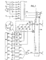
- FIG. 1 the overall architecture of the integrated circuit memory is shown, not allowing a group test after the redundancy has been put into service.
- the example shown is that of a memory with column addressing by four address bits, with two redundancy columns capable of replacing two defective columns, and with a grouped test mode allowing programming of four columns at a time.
- this embodiment is given only by way of a simplified example, the numbers of address bits and of columns being much higher in practice.
- the memory map itself with its rows and columns of cells is not shown; access to the memory cell columns of the memory plane is established by a column address decoder (DEC) whose PYM outputs are equal in number to the number of memory columns: each output line makes it possible to select, when 'it is at the appropriate logical level, a particular column of memory.
- DEC column address decoder
- the decoder receives on address bit inputs and on complementary inputs respectively the address bits A1, A2, A3, A4 and the complements NA1, NA2, NA3, NA4 of these bits.
- a given column is selected by the decoder. But if an input and the corresponding complementary input (for example A1 and NA1) of the decoder are forced to the same logic level 1 (instead of complementary levels 1 and 0), two columns are selected. And if you force two inputs and the two corresponding complementary inputs (for example A1 and A2 and NA1 and NA2) all at the same logic level 1, then four columns are selected simultaneously. The four columns which are thus selected simultaneously are defined by the other address bits (A3 and A4 here).
- a group test control signal G is applied to a set of logic gates (NOR gates) interposed between the address inputs of the memory and the inputs of the decoder.
- G logic level 1
- NOR gates logic gates
- a DSL deselection circuit makes it possible to deselect the column designated by the decoder and to select a replacement column instead.
- This DSL circuit receives the PYM outputs from the decoder and a CAB deselection control signal. If CAB is at logic level 1, the PYM output is inhibited and no longer allows the column designated by the decoder to be selected.
- the signal CAB is supplied by a comparison circuit CMP; it is 1 when the address presented at the input of the decoder is a defective column address.
- the DSL circuit receives the outputs PYM for designating the column to be selected and it supplies, under the control of the deselection signal CAB, as many outputs YM which are command lines for selecting columns from the memory and an additional output YR which is a command line for selecting a first redundant column.
- two redundancy columns are in fact provided, for example one associated with one half of the columns and the other with the other half, or both associated with all of the columns;
- the CAB signal makes it possible to deselect a defective column in order to select the first replacement column instead; this selection is made using the YR command line;
- a CAB signal ' makes it possible to deselect a defective column to select another replacement column by activating another command line YR'.
- the addresses of defective columns, identified during the memory test, are stored in redundancy memories, produced in the form of fuse banks or electrically programmable and non-erasable memories (UPROM).
- a first four-bit address is stored in a memory area MR associated with the first replacement column; another address can be stored in a second redundancy memory zone MR ′ associated with the second replacement column. These two addresses represent the addresses of two defective memory columns.
- the comparison is carried out from circuits organized in the following manner: the faulty column address bits, represented by the outputs NF1, NF2, NF3, NF4, of the memory MR, are used to each command a respective switch SW1, SW2 , SW3, SW4. Each switch also receives the signals present on an input and a respective complementary input of the decoder.
- the switch SW1 receives as control signal NF1 (first defective column address bit) and as signals to switch A1 (first input of the decoder DEC) and NA1 (first complementary input of the decoder).
- NF1 first defective column address bit
- NA1 first complementary input of the decoder
- the output signal XA1 of the switch SW1 is then equal to 0 if the stored address bit corresponds to the address bit received at the input of the memory.
- all the output signals XA1 to XA4 of the switches connected at the output of the redundancy memory all pass to 0.
- the signal of CAB deselection is then activated.
- a simple NOR gate (designated by CMP in the figure) receiving all the signals XA1 to XA4 provides at its output the signal CAB. This gate NOR is here produced by transistors in parallel whose gates receive the signals XA1 to XA4.
- the NOR CMP gate is modified as follows: it receives the complement NG of the signal G of the group test command. This signal NG prohibits the zeroing of the signal CAB under the effect of the signals XA1 and XA2, that is to say the output signals of the switches SW1 and SW2 which correspond to the address bits grouped during the group test.
- bits A3 and A4 correspond to a defective column address
- the signal CAB will go to 1 and allow the selection of the redundant column; indeed, the defective column is then one of the four columns selected by the group test and it must be replaced by the redundant column.
- the four grouped columns should not be deselected since they must be tested (whereas changing the CAB signal to 1 deselects them all); this is why there is interposed in the DSL deselection circuit a logic gate ND receiving the signal CAB or its complement and the signal G of grouped test or its complement; this door neutralizes the deselection when the signal G indicates that we are in group test mode.
- the ND gate prevents the CAB signal from affecting the transmission of the PYM output signals from the decoder to the columns of the memory plane.
Landscapes
- For Increasing The Reliability Of Semiconductor Memories (AREA)
- Techniques For Improving Reliability Of Storages (AREA)
Abstract
Description
L'invention concerne les mémoires réalisées en circuit intégré, tout particulièrement mais non exclusivement les mémoires non volatiles programmables électriquement.The invention relates to memories produced in integrated circuit, very particularly but not exclusively to electrically programmable non-volatile memories.
Dans les mémoires de grande capacité (plusieurs dizaines de milliers de cellules de mémoire), on a l'habitude, pour améliorer les rendements de fabrication, d'associer au plan mémoire plusieurs colonnes (ou lignes) de redondance destinées à se substituer à des colonnes (ou lignes) défectueuses du plan mémoire. Dans la suite, pour simplifier, on ne parlera plus que de colonnes mais il pourrait s'agir aussi de lignes.In large-capacity memories (several tens of thousands of memory cells), it is customary, in order to improve manufacturing yields, to associate several memory columns (or rows) of redundancy intended to replace the memory plane. defective columns (or rows) of the memory map. In the following, for simplicity, we will only talk about columns but it could also be rows.
Pour l'utilisateur, la substitution doit être transparente, c'est-à-dire qu'il est autorisé à envoyer à l'entrée d'adressage de la mémoire une adresse correspondant à une colonne défectueuse; la circui- terie interne de redondance se charge alors de neutraliser la colonne défectueuse et de lire ou écrire une information dans une cellule d'une colonne de remplacement au lieu de tenter de la lire ou de l'écrire dans une cellule de la colonne défectueuse.For the user, the substitution must be transparent, that is to say that he is authorized to send to the addressing address of the memory an address corresponding to a defective column; the internal redundancy circuit then takes care of neutralizing the defective column and of reading or writing information in a cell of a replacement column instead of trying to read or write it in a cell of the defective column .
Cette transparence impose de placer à l'entrée de la mémoire des circuits de reconnaissance des adresses défectueuses, des circuits de désélection pour neutraliser les colonnes défectueuses, et des circuits de routage vers les colonnes de remplacement.This transparency requires placing faulty address recognition circuits, deselection circuits to neutralize defective columns, and routing circuits to replacement columns at the memory input.
Tous ces circuits modifient donc de manière importante le décodage initial des adresses de la mémoire, décodage qui consistait à associer une colonne déterminée à une adresse d'entrée déterminée.All these circuits therefore significantly modify the initial decoding of the addresses of the memory, decoding which consisted in associating a determined column with a determined input address.
Or il se trouve qu'en dehors du mode d'utilisation normale des mémoires (lecture et écriture par un utilisateur avec transparence complète dans le cas où des colonnes redondantes ont été mises en service), il existe un deuxième mode qui est le mode de test.Now it turns out that apart from the normal mode of use of the memories (reading and writing by a user with complete transparency in the case where redundant columns have been put into service), there is a second mode which is the mode of test.
En effet, il est nécessaire que toutes les cellules des mémoires soient testées avant que le circuit soit déclaré apte à être vendu. Le test consiste notamment à programmer toutes les cellules de leur état initial (état vierge) vers un état "programmé" et à vérifier qu'elles sont correctement programmées. C'est d'ailleurs en général au cours de ce test qu'on détecte des colonnes défectueuses et qu'on met en service des colonnes de remplacement.In fact, it is necessary that all the memory cells be tested before the circuit is declared fit to be sold. The test consists in particular in programming all the cells from their initial state (blank state) to a "programmed" state and in verifying that they are correctly programmed. It is moreover generally during this test that defective columns are detected and that replacement columns are put into service.
Le test d'une cellule de mémoire peut prendre quelques millisecondes. Mais les circuits intégrés sont fabriqués par lots, et chaque lot comporte des dizaines de tranches de silicium portant chacune plusieurs dizaines de puces qui portent elles mêmes chacune plusieurs dizaines ou centaines de milliers de cellules de mémoire; les opérations de test peuvent alors prendre un temps considérable puisqu'il faut tester systématiquement toutes les cellules.Testing a memory cell can take a few milliseconds. However, integrated circuits are manufactured in batches, and each batch comprises dozens of silicon wafers each carrying several tens of chips which themselves each carry several tens or hundreds of thousands of memory cells; the testing operations can then take a considerable time since it is necessary to systematically test all the cells.
Pour réduire ce temps de test, on a proposé que les cellules soient programmées selon un motif (par exemple un motif en damier) qui permette la programmation simultanée de plusieurs colonnes de points mémoire. Autrement dit, en mode de test, au lieu d'écrire individuellement dans une colonne puis dans une autre, etc, on écrit simultanément une même information en parallèle dans plusieurs colonnes à la fois, par exemple 2 ou 4 ou 8 colonnes à la fois. Le temps de test est divisé d'autant.To reduce this test time, it has been proposed that the cells be programmed according to a pattern (for example a checkerboard pattern) which allows the simultaneous programming of several columns of memory points. In other words, in test mode, instead of writing individually in one column then in another, etc., we write simultaneously the same information in parallel in several columns at the same time, for example 2 or 4 or 8 columns at a time . The test time is divided accordingly.
On peut appeler dans la suite "test groupé" ce mode de test dans lequel on programme plusieurs colonnes à la fois.We can call in the following "group test" this test mode in which we program several columns at the same time.
On a remarqué selon l'invention que dans les mémoires existantes on ne pouvait pas faire deux fois de suite un test groupé alors qu'on peut très bien avoir besoin de le faire dans certaines circonstances.It has been observed according to the invention that in existing memories it was not possible to carry out a group test twice in succession, whereas it may very well be necessary to do so in certain circumstances.
Par exemple, on a besoin de recommencer un test pour tout un lot dans le cas où une fausse manoeuvre a été effectuée au cours du test du lot; ou encore si le testeur est tombé en panne et que la panne n'a pas été détectée assez vite, etc.For example, we need to repeat a test for an entire batch in the event that a false maneuver was carried out during the batch test; or if the tester has broken down and the fault has not been detected quickly enough, etc.
Et on ne peut pas refaire le test en mode "groupé" pour les lots déjà testés : en effet, des colonnes de redondance ont été mises en service (de manière irréversible) dans certaines puces, et cette mise en service s'accompagne de modifications importantes de l'adressage interne de la mémoire. Or le mode de test "groupé" nécessite lui aussi une modification de l'adressage interne de la mémoire puisqu'il exige d'adresser simultanément plusieurs colonnes.And we cannot repeat the test in "grouped" mode for the batches already tested: indeed, redundancy columns have been put into service (irreversibly) in certain chips, and this putting into service is accompanied by modifications of the internal memory addressing. However, the "grouped" test mode also requires a modification of the internal addressing of the memory since it requires addressing several columns simultaneously.
On s'est aperçu que les modifications d'adressage dues à la mise en service de colonnes de redondance étaient en pratique incompatibles avec les modifications d'adressage requises pour effectuer un mode de test groupé. Il n'est donc pas possible de refaire un test groupé si le premier test effectué a abouti à la mise en service de colonnes de remplacement.It has been found that the addressing modifications due to the commissioning of redundancy columns were in practice incompatible with the addressing modifications required to perform a group test mode. It is therefore not possible to repeat a group test if the first test carried out resulted in the commissioning of replacement columns.
On propose selon l'invention une mémoire dans laquelle les moyens d'adressage en mode de test groupé, permettant d'adresser simultanément un groupe de plusieurs colonnes, sont aptes à sélectionner simultanément, en vue de les programmer, non seulement les colonnes de ce groupe mais, si l'une des colonnes du groupe est défectueuse et associée à une colonne de remplacement, la colonne de remplacement.A memory is proposed according to the invention in which the addressing means in group test mode, making it possible to address simultaneously a group of several columns, are capable of simultaneously selecting, in order to program them, not only the columns of this group but, if one of the columns in the group is defective and associated with a replacement column, the replacement column.
De cette manière, on peut recommencer le test groupé; dans l'art antérieur, si on devait refaire un test de la mémoire, il fallait passer en mode de test simple (non groupé), c'est-à-dire colonne par colonne.In this way, you can start the group test again; in the prior art, if we had to repeat a memory test, we had to switch to simple test mode (not grouped), that is to say column by column.
Dans une réalisation particulière de la mémoire, il y a un décodeur d'adresses de colonne recevant sur des entrées d'adresse les bits d'une adresse de colonne et sur des entrées complémentaires les compléments de ces bits, une mémoire de redondance pour stocker des adresses de colonnes défectueuses, un circuit de comparaison des adresses reçues et des adresses de colonnes défectueuses; le circuit de comparaison des adresses reçues et des adresses défectueuses comporte une porte NOR a plusieurs entrées, chaque entrée recevant un bit dont le niveau logique dépend de l'identité entre un bit reçu sur une entrée du décodeur et un bit correspondant de la mémoire de redondance; un moyen est prévu pour sélectionner une colonne de remplacement et simultanément désélectionner une colonne défectueuse lorsque la sortie de la porte NOR indique qu'une adresse reçue est identique à une adresse défectueuse; le test groupé est commandé par un circuit logique qui, en réponse à un signal de commande de test groupé, place un niveau logique identique sur au moins une entrée et une entrée complémentaire correspondante du décodeur; et le signal de commande de test groupé est appliqué au circuit de comparaison pour empêcher que la colonne de remplacement soit systématiquement mise hors service lors du test groupé.In a particular embodiment of the memory, there is a column address decoder receiving on address inputs the bits of a column address and on complementary inputs the complements of these bits, a redundancy memory for storing addresses of defective columns, a circuit for comparing the addresses received and addresses of defective columns; the circuit for comparing addresses received and defective addresses comprises a NOR gate with several inputs, each input receiving a bit whose logic level depends on the identity between a bit received on an input of the decoder and a corresponding bit of the redundancy memory ; means are provided for selecting a replacement column and simultaneously deselecting a defective column when the output from the NOR gate indicates that a received address is identical to a defective address; the group test is controlled by a logic circuit which, in response to a group test control signal, places an identical logic level on at least one input and a corresponding complementary input of the decoder; and the group test command signal is applied to the comparison circuit to prevent the replacement column from being systematically taken out of service during the group test.
D'autres caractéristiques et avantages de l'invention apparaîtront à la lecture de la description détaillée qui suit et qui est faite en référence aux dessins annexés dans lesquels :
- - la figure 1 représente un circuit de mémoire avec redondance, ne permettant pas un test groupé après que la redondance ait été mise en service;
- - la figure 2 représente un circuit de mémoire selon l'invention permettant un test groupé même après mise en service de la redondance.
- - Figure 1 shows a memory circuit with redundancy, not allowing a group test after the redundancy has been put into service;
- - Figure 2 shows a memory circuit according to the invention allowing a group test even after commissioning of the redundancy.
A la figure 1, on a représenté l'architecture globale de la mémoire en circuit intégré ne permettant pas un test groupé après que la redondance ait été mise en service. L'exemple représenté est celui d'une mémoire avec adressage des colonnes par quatre bits d'adresse, avec deux colonnes de redondance susceptibles de remplacer deux colonnes défectueuses, et avec un mode de test groupé permettant de programmer quatre colonnes à la fois. Bien entendu, cette réalisation n'est donnée qu'à titre d'exemple simplifié, les nombres de bits d'adresse et de colonnes étant bien supérieurs dans la pratique.In FIG. 1, the overall architecture of the integrated circuit memory is shown, not allowing a group test after the redundancy has been put into service. The example shown is that of a memory with column addressing by four address bits, with two redundancy columns capable of replacing two defective columns, and with a grouped test mode allowing programming of four columns at a time. Of course, this embodiment is given only by way of a simplified example, the numbers of address bits and of columns being much higher in practice.
Le plan mémoire lui-même avec ses lignes et colonnes de cellules n'est pas représenté; l'accès aux colonnes de cellules de mémoire du plan mémoire est établi par un décodeur d'adresses de colonne (DEC) dont les sorties PYM sont en nombre égal au nombre de colonnes de la mémoire : chaque ligne de sortie permet de sélectionner, lorsqu'elle est au niveau logique approprié, une colonne particulière de la mémoire.The memory map itself with its rows and columns of cells is not shown; access to the memory cell columns of the memory plane is established by a column address decoder (DEC) whose PYM outputs are equal in number to the number of memory columns: each output line makes it possible to select, when 'it is at the appropriate logical level, a particular column of memory.
Le décodeur reçoit sur des entrées de bit d'adresse et sur des entrées complémentaires respectivement les bits d'adresse A1, A2, A3, A4 et les compléments NA1, NA2, NA3, NA4 de ces bits.The decoder receives on address bit inputs and on complementary inputs respectively the address bits A1, A2, A3, A4 and the complements NA1, NA2, NA3, NA4 of these bits.
Pour une adresse donnée, une colonne donnée est sélectionnée par le décodeur. Mais si on force au même niveau logique 1 (au lieu de niveaux complémentaires 1 et 0) une entrée et l'entrée complémentaire correspondante (par exemple A1 et NA1) du décodeur, deux colonnes sont sélectionnées. Et si on force deux entrées et les deux entrées complémentaires correspondantes (par exemple A1 et A2 et NA1 et NA2) toutes au même niveau logique 1, alors quatre colonnes sont sélectionnées simultanément. Les quatre colonnes qui sont ainsi sélectionnées simultanément sont définies par les autres bits d'adresse (A3 et A4 ici).For a given address, a given column is selected by the decoder. But if an input and the corresponding complementary input (for example A1 and NA1) of the decoder are forced to the same logic level 1 (instead of complementary levels 1 and 0), two columns are selected. And if you force two inputs and the two corresponding complementary inputs (for example A1 and A2 and NA1 and NA2) all at the same logic level 1, then four columns are selected simultaneously. The four columns which are thus selected simultaneously are defined by the other address bits (A3 and A4 here).
C'est ce qui est mis à profit pour effectuer, en mode de test, un test "groupé" avec programmation simultanée de plusieurs colonnes.This is what is used to perform, in test mode, a "grouped" test with simultaneous programming of several columns.
Pour cela, un signal de commande de test groupé G est appliqué à un ensemble de portes logiques (portes NOR) interposées entre les entrées d'adresse de la mémoire et les entrées du décodeur. Lorsque G est au niveau logique 1, un niveau 1 est appliqué à la fois sur les entrées A1, A2 et les entrées complémentaires NA1, NA2 du décodeur. Lorsque G=0, les entrées NA1 et NA2 sont les compléments des entrées A1 et A2. Le signal G n'agit pas sur les autres bits d'adresse dans cette réalisation où le test groupé consiste à programmer quatre colonnes à la fois.For this, a group test control signal G is applied to a set of logic gates (NOR gates) interposed between the address inputs of the memory and the inputs of the decoder. When G is at logic level 1, a level 1 is applied to both the inputs A1, A2 and the complementary inputs NA1, NA2 of the decoder. When G = 0, the inputs NA1 and NA2 are the complements of the inputs A1 and A2. The signal G does not act on the other address bits in this embodiment where the grouped test consists in programming four columns at a time.
Pour la réparation de colonnes défectueuses, la mémoire est organisée de la manière suivante : un circuit de désélection DSL permet de désélectionner la colonne désignée par le décodeur et de sélectionner à la place une colonne de remplacement. Ce circuit DSL reçoit les sorties PYM du décodeur et un signal de commande de désélection CAB. Si CAB est au niveau logique 1, la sortie PYM est inhibée et ne permet plus de sélectionner la colonne désignée par le décodeur. Le signal CAB est fourni par un circuit de comparaison CMP; il est à 1 quand l'adresse présentée à l'entrée du décodeur est une adresse de colonne défectueuse.For the repair of defective columns, the memory is organized as follows: a DSL deselection circuit makes it possible to deselect the column designated by the decoder and to select a replacement column instead. This DSL circuit receives the PYM outputs from the decoder and a CAB deselection control signal. If CAB is at logic level 1, the PYM output is inhibited and no longer allows the column designated by the decoder to be selected. The signal CAB is supplied by a comparison circuit CMP; it is 1 when the address presented at the input of the decoder is a defective column address.
Plus précisément, le circuit DSL reçoit les sorties PYM de désignation de colonne à sélectionner et il fournit, sous le contrôle du signal de désélection CAB, autant de sorties YM qui sont des lignes de commande de sélection des colonnes de la mémoire et une sortie additionnelle YR qui est une ligne de commande de sélection d'une première colonne redondante.More specifically, the DSL circuit receives the outputs PYM for designating the column to be selected and it supplies, under the control of the deselection signal CAB, as many outputs YM which are command lines for selecting columns from the memory and an additional output YR which is a command line for selecting a first redundant column.
Dans l'exemple représenté on a prévu en fait deux colonnes de redondance, par exemple une associée à une moitié des colonnes et l'autre à l'autre moitié, ou toutes les deux associées à l'ensemble des colonnes; le signal CAB permet de désélectionner une colonne défectueuse pour sélectionner à la place la première colonne de remplacement; cette sélection se fait par la ligne de commande YR; un signal CAB' permet de désélectionner une colonne défectueuse pour sélectionner une autre colonne de remplacement en activant une autre ligne de commande YR'.In the example shown, two redundancy columns are in fact provided, for example one associated with one half of the columns and the other with the other half, or both associated with all of the columns; the CAB signal makes it possible to deselect a defective column in order to select the first replacement column instead; this selection is made using the YR command line; a CAB signal 'makes it possible to deselect a defective column to select another replacement column by activating another command line YR'.
Les adresses de colonnes défectueuses, repérées lors du test de la mémoire, sont stockées dans des mémoires de redondance, réalisées sous forme de batteries de fusibles ou de mémoires électriquement programmables et non effaçables (UPROM). Une première adresse à quatre bits est stockée dans une zone de mémoire MR associée à la première colonne de remplacement; une autre adresse peut être stockée dans une deuxième zone de mémoire de redondance MR' associée à la deuxième colonne de remplacement. Ces deux adresses représentent les adresses de deux colonnes défectueuses de la mémoire.The addresses of defective columns, identified during the memory test, are stored in redundancy memories, produced in the form of fuse banks or electrically programmable and non-erasable memories (UPROM). A first four-bit address is stored in a memory area MR associated with the first replacement column; another address can be stored in a second redundancy memory zone MR ′ associated with the second replacement column. These two addresses represent the addresses of two defective memory columns.
Par comparaison entre l'adresse reçue et l'adresse stockée en mémoire MRon élabore le signal de désélection CAB. Par comparaison entre l'adresse reçue et l'adresse stockée en MR', on élabore le signal CAB'.By comparison between the address received and the address stored in memory MRon develops the deselection signal CAB. By comparison between the address received and the address stored in MR ', the signal CAB' is produced.
La comparaison est effectuée à partir de circuits organisés de la manière suivante : les bits d'adresse de colonne défectueuse, représentés par les sorties NF1, NF2, NF3, NF4, de la mémoire MR, servent à commander chacun un aiguillage respectif SW1, SW2, SW3, SW4. Chaque aiguillage reçoit par ailleurs les signaux présents sur une entrée et une entrée complémentaire respective du décodeur. Ainsi, l'aiguillage SW1 reçoit comme signal de commande NF1 (premier bit d'adresse de colonne défectueuse) et comme signaux à aiguiller A1 (première entrée du décodeur DEC) et NA1 (première entrée complémentaire du décodeur). Selon l'état de NF1, c'est A1 ou NA1 qui est aiguillé à la sortie de SW1. Le signal de sortie XA1 de l'aiguillage SW1 est alors égal à 0 si le bit d'adresse stocké correspond au bit d'adresse reçue à l'entrée de la mémoire. Quand tous les bits d'adresse stockés dans la mémoire MR correspondent justement aux bits d'adresse reçus par la mémoire, tous les signaux de sortie XA1 à XA4 des aiguillages connectés en sortie de la mémoire de redondance passent tous à 0. Le signal de désélection CAB est alors activé. Une simple porte NOR (désignée par CMP sur la figure) recevant tous les signaux XA1 à XA4 fournit à sa sortie le signal CAB. Cette porte NORest ici réalisée par des transistors en parallèle dont les grilles reçoivent les signaux XA1 à XA4.The comparison is carried out from circuits organized in the following manner: the faulty column address bits, represented by the outputs NF1, NF2, NF3, NF4, of the memory MR, are used to each command a respective switch SW1, SW2 , SW3, SW4. Each switch also receives the signals present on an input and a respective complementary input of the decoder. Thus, the switch SW1 receives as control signal NF1 (first defective column address bit) and as signals to switch A1 (first input of the decoder DEC) and NA1 (first complementary input of the decoder). Depending on the state of NF1, it is A1 or NA1 which is routed at the output of SW1. The output signal XA1 of the switch SW1 is then equal to 0 if the stored address bit corresponds to the address bit received at the input of the memory. When all the address bits stored in the memory MR correspond precisely to the address bits received by the memory, all the output signals XA1 to XA4 of the switches connected at the output of the redundancy memory all pass to 0. The signal of CAB deselection is then activated. A simple NOR gate (designated by CMP in the figure) receiving all the signals XA1 to XA4 provides at its output the signal CAB. This gate NOR is here produced by transistors in parallel whose gates receive the signals XA1 to XA4.
L'élaboration du signal CAB' est identique, à partir du contenu de la mémoire MR'.The processing of the signal CAB 'is identical, from the content of the memory MR'.
En pratique, pour élaborer XA1 à partir de NF1, de A1, et de NA1, on utilise un petit circuit d'aiguillage SW1 à deux transistors à canal N en série entre A1 et NA1, leurs grilles étant commandées par NF1 et l'inverse de NF1 respectivement. Les autres circuits d'aiguillage sont identiques.In practice, to develop XA1 from NF1, A1, and NA1, we use a small switching circuit SW1 with two N-channel transistors in series between A1 and NA1, their gates being controlled by NF1 and the reverse. of NF1 respectively. The other switching circuits are identical.
Or ce circuit fournit XA1 comme désiré (XA1 = 0 si le bit d'adresse reçu correspond au bit stocké) seulement si A1 et NA1 sont bien des signaux complémentaires. Si A1 et NA1 sont tous deux égaux à 1, XA1 ne peut pas être autre chose que 1. Et si XA1 (ou XA2) est égal à 1, le signal CAB ne peut plus passer à 1.However, this circuit supplies XA1 as desired (XA1 = 0 if the address bit received corresponds to the stored bit) only if A1 and NA1 are indeed complementary signals. If A1 and NA1 are both equal to 1, XA1 cannot be anything other than 1. And if XA1 (or XA2) is equal to 1, the signal CAB can no longer pass to 1.
Il résulte de cela que la colonne de redondance ne peut pas être sélectionnée dès lors que A1 et NA1 sont tous deux égaux à 1; or c'est ce qui se passe en mode de test groupé : A1 et NA1 sont tous deux égaux à 1, de même que A2 et NA2 d'ailleurs.It follows from this that the redundancy column cannot be selected since A1 and NA1 are both equal to 1; however this is what happens in group test mode: A1 and NA1 are both equal to 1, as are A2 and NA2 moreover.
Lors du premier test de la mémoire, cela n'a pas d'importance, aucune colonne de redondance n'a été mise en service. Mais si on veut faire un deuxième test groupé après avoir mis en service des colonnes de redondance parce qu'il y a des colonnes défectueuses, les colonnes défectueuses seront à nouveau testées, mais il n'y aura évidemment plus de possibilité de les réparer puisqu'elles l'ont en fait déjà été; et même si elles étaient remplacées à nouveau, on ne pourrait de toutes façons pas vérifier (en mode de test groupé) que la réparation est correcte.During the first memory test, this does not matter, no redundancy column has been put into service. But if we want to do a second group test after having put redundancy columns into service because there are defective columns, the defective columns will be tested again, but there will obviously be no possibility of repairing them since 'they have in fact already been; and even if they were replaced again, we could not in any case verify (in group test mode) that the repair is correct.
On comprendra donc qu'il n'est pas possible de refaire un test groupé.It will therefore be understood that it is not possible to repeat a group test.
Avec le circuit de la figure 2, le test groupé redevient possible.With the circuit of figure 2, the group test becomes possible again.
Pour cela on prévoit que les circuits de comparaison (porte NOR CMP et aiguillages SW1 à SW4) sont modifiés pour empêcher la désélection systématique de la colonne de redondance en mode de test groupé.For this, provision is made for the comparison circuits (NOR CMP gate and switches SW1 to SW4) to be modified to prevent systematic deselection of the redundancy column in group test mode.
Dans l'exemple décrit la porte NOR CMP est modifiée de la manière suivante : elle reçoit le complément NG du signal G de commande de test groupé. Ce signal NG interdit la mise à zéro du signal CAB sous l'effet des signaux XA1 et XA2, c'est-à-dire des signaux de sortie des aiguillages SW1 et SW2 qui correspondent aux bits d'adresse groupés lors du test groupé.In the example described, the NOR CMP gate is modified as follows: it receives the complement NG of the signal G of the group test command. This signal NG prohibits the zeroing of the signal CAB under the effect of the signals XA1 and XA2, that is to say the output signals of the switches SW1 and SW2 which correspond to the address bits grouped during the group test.
Ainsi, lorsque les bits A3 et A4 correspondront à une adresse de colonne défectueuse, le signal CAB passera à 1 et permettra la sélection de la colonne redondante; en effet, la colonne défectueuse est alors une des quatre colonnes sélectionnées par le test groupé et elle doit être remplacée par la colonne redondante.Thus, when bits A3 and A4 correspond to a defective column address, the signal CAB will go to 1 and allow the selection of the redundant column; indeed, the defective column is then one of the four columns selected by the group test and it must be replaced by the redundant column.
Toutefois, il ne faudrait pas désélectionner les quatre colonnes groupées puisqu'elles doivent être testées (alors que le passage à 1 du signal CAB les désélectionne toutes); c'est pourquoi on interpose dans le circuit de désélection DSL une porte logique ND recevant le signal CAB ou son complément et le signal G de test groupé ou son complément; cette porte neutralise la désélection lorsque le signal G indique qu'on est en mode de test groupé. La porte ND empêche que le signal CAB vienne affecter la transmission des signaux de sortie PYM du décodeur vers les colonnes du plan mémoire.However, the four grouped columns should not be deselected since they must be tested (whereas changing the CAB signal to 1 deselects them all); this is why there is interposed in the DSL deselection circuit a logic gate ND receiving the signal CAB or its complement and the signal G of grouped test or its complement; this door neutralizes the deselection when the signal G indicates that we are in group test mode. The ND gate prevents the CAB signal from affecting the transmission of the PYM output signals from the decoder to the columns of the memory plane.
Bien entendu, les mêmes dispositions sont prises pour l'élaboration et la transmission du signal CAB' : modification d'une porte NOR CMP' par le signal NG et interposition d'une porte logique ND' commandée par G.Of course, the same arrangements are made for the preparation and transmission of the signal CAB ': modification of a NOR CMP gate' by the signal NG and interposition of a logic gate ND 'commanded by G.
Claims (2)
Applications Claiming Priority (2)
| Application Number | Priority Date | Filing Date | Title |
|---|---|---|---|
| FR9010247A FR2665793B1 (en) | 1990-08-10 | 1990-08-10 | INTEGRATED MEMORY CIRCUIT WITH REDUNDANCY AND IMPROVED ADDRESSING IN TEST MODE. |
| FR9010247 | 1990-08-10 |
Publications (2)
| Publication Number | Publication Date |
|---|---|
| EP0470897A1 true EP0470897A1 (en) | 1992-02-12 |
| EP0470897B1 EP0470897B1 (en) | 1993-12-15 |
Family
ID=9399605
Family Applications (1)
| Application Number | Title | Priority Date | Filing Date |
|---|---|---|---|
| EP91402169A Expired - Lifetime EP0470897B1 (en) | 1990-08-10 | 1991-08-02 | Integrated memory circuit with redundancy and improved addressing in test mode |
Country Status (4)
| Country | Link |
|---|---|
| US (1) | US5247481A (en) |
| EP (1) | EP0470897B1 (en) |
| DE (1) | DE69100796T2 (en) |
| FR (1) | FR2665793B1 (en) |
Families Citing this family (11)
| Publication number | Priority date | Publication date | Assignee | Title |
|---|---|---|---|---|
| US5588115A (en) * | 1993-01-29 | 1996-12-24 | Teradyne, Inc. | Redundancy analyzer for automatic memory tester |
| US6101618A (en) * | 1993-12-22 | 2000-08-08 | Stmicroelectronics, Inc. | Method and device for acquiring redundancy information from a packaged memory chip |
| US5530674A (en) * | 1994-04-29 | 1996-06-25 | Sgs-Thomson Microelectronics, Inc. | Structure capable of simultaneously testing redundant and non-redundant memory elements during stress testing of an integrated circuit memory device |
| JP3865828B2 (en) | 1995-11-28 | 2007-01-10 | 株式会社ルネサステクノロジ | Semiconductor memory device |
| US5754556A (en) * | 1996-07-18 | 1998-05-19 | Teradyne, Inc. | Semiconductor memory tester with hardware accelerators |
| JPH1166882A (en) * | 1997-08-19 | 1999-03-09 | Nec Corp | Semiconductor storage device |
| US6022788A (en) * | 1997-12-23 | 2000-02-08 | Stmicroelectronics, Inc. | Method of forming an integrated circuit having spacer after shallow trench fill and integrated circuit formed thereby |
| JP2001312897A (en) | 2000-04-27 | 2001-11-09 | Nec Corp | Memory test device and test method |
| TW577997B (en) * | 2002-06-19 | 2004-03-01 | Nanya Technology Corp | Memory module testing/repairing method |
| US20040099644A1 (en) * | 2002-10-18 | 2004-05-27 | Allen John R. | System and method for post weld conditioning |
| US6980478B1 (en) * | 2004-09-01 | 2005-12-27 | Micron Technology, Inc. | Zero-enabled fuse-set |
Citations (2)
| Publication number | Priority date | Publication date | Assignee | Title |
|---|---|---|---|---|
| EP0050005A2 (en) * | 1980-10-15 | 1982-04-21 | Kabushiki Kaisha Toshiba | Semiconductor memory with improved data programming time |
| EP0264893A2 (en) * | 1986-10-20 | 1988-04-27 | Nippon Telegraph And Telephone Corporation | Semiconductor memory |
Family Cites Families (4)
| Publication number | Priority date | Publication date | Assignee | Title |
|---|---|---|---|---|
| US4939694A (en) * | 1986-11-03 | 1990-07-03 | Hewlett-Packard Company | Defect tolerant self-testing self-repairing memory system |
| JPH0697560B2 (en) * | 1987-11-19 | 1994-11-30 | 三菱電機株式会社 | Semiconductor memory device |
| FR2629248B1 (en) * | 1988-03-25 | 1992-04-24 | Sgs Thomson Microelectronics | SINGLE PROGRAMMING MEMORY TESTING METHOD AND CORRESPONDING MEMORY |
| FR2636464B1 (en) * | 1988-09-14 | 1990-10-26 | Sgs Thomson Microelectronics | EPROM MEMORY WITH INTERNAL SIGNATURE CONCERNING IN PARTICULAR THE PROGRAMMING MODE |
-
1990
- 1990-08-10 FR FR9010247A patent/FR2665793B1/en not_active Expired - Fee Related
-
1991
- 1991-08-02 EP EP91402169A patent/EP0470897B1/en not_active Expired - Lifetime
- 1991-08-02 DE DE91402169T patent/DE69100796T2/en not_active Expired - Fee Related
- 1991-08-08 US US07/742,298 patent/US5247481A/en not_active Expired - Lifetime
Patent Citations (2)
| Publication number | Priority date | Publication date | Assignee | Title |
|---|---|---|---|---|
| EP0050005A2 (en) * | 1980-10-15 | 1982-04-21 | Kabushiki Kaisha Toshiba | Semiconductor memory with improved data programming time |
| EP0264893A2 (en) * | 1986-10-20 | 1988-04-27 | Nippon Telegraph And Telephone Corporation | Semiconductor memory |
Non-Patent Citations (2)
| Title |
|---|
| IEEE ELECTRO, vol. 7, mai 1982, pages 26/3(1-6), New York, U,S.; J.P. ALTNETHER et al.: Testing Redundant Memories" *page 2, colonne de droite, ligne 14- page3, colonne de gauche, ligne 13* *page 3, colonne de gauche, ligne36- page 3, colonne de droite, ligne 4; figures 2,4* * |
| RESEARCH DISCLOSURE. no. 299, Mars 1989, HAVANT GB DISCLOSURE NO. 29929: 'Fast Write Scheme for Memory Test Patterns' * |
Also Published As
| Publication number | Publication date |
|---|---|
| US5247481A (en) | 1993-09-21 |
| FR2665793B1 (en) | 1993-06-18 |
| EP0470897B1 (en) | 1993-12-15 |
| DE69100796D1 (en) | 1994-01-27 |
| FR2665793A1 (en) | 1992-02-14 |
| DE69100796T2 (en) | 1994-04-21 |
Similar Documents
| Publication | Publication Date | Title |
|---|---|---|
| EP0666573B1 (en) | Non volatile flip-flop, programmed via the source, especially for memory redundancy circuit | |
| EP0666572B1 (en) | Non volatile programmable flip-flop with predefined initial state, especially for memory redundancy circuit | |
| EP0674264B1 (en) | Circuit for selecting redundant memory elements and FLASH EEPROM containing said circuit | |
| EP0470897B1 (en) | Integrated memory circuit with redundancy and improved addressing in test mode | |
| EP0669576B1 (en) | Memory redundancy circuit | |
| FR2787233A1 (en) | Verifying integrity of decoding circuits of memory matrix by performing at least N or M writing of second words in storage in such way that every line and every column has at least registered second word | |
| FR2718560A1 (en) | Method and circuit for repairing a fault in a semiconductor memory device. | |
| EP0334763B1 (en) | Method of testing a fleeting programmable memory, and this memory | |
| FR2770327A1 (en) | Electrically erasable programmable read only memory | |
| EP0544568B1 (en) | Reading circuit for redundancy fuse for integrated memory | |
| EP0838826B1 (en) | Electrically alterable non-volatile multilevel memory having internal refreshing means | |
| EP0645714A1 (en) | Dynamic redundancy circuit for integrated circuit memory | |
| FR2611301A1 (en) | Integrated memory with data column redundancy | |
| EP0665559B1 (en) | Non volatile programmable flip-flop, with reduction of parasitic effects in read mode, especially for memory redundancy circuit | |
| EP0676769B1 (en) | Electrically alterable read only memory comprising test functions | |
| EP0606793B1 (en) | Method for repairing defective elements in a redundant memory | |
| EP0659291A1 (en) | Memory circuit with redundancy architecture | |
| US6601194B1 (en) | Circuit configuration for repairing a semiconductor memory | |
| EP0432004B1 (en) | Redundancy circuit with the memorization of the position of the output | |
| FR2843208A1 (en) | Electronic circuit repair, e.g. for memory circuits, whereby electronic modules are sub-divided into parts so that test results are relative to module parts rather than whole modules, thus reducing the redundant circuit surface | |
| FR2655763A1 (en) | REDUNDANCY CIRCUIT FOR MEMORY. | |
| EP0938095B1 (en) | Programmable non-volatile memory and programming method thereof | |
| EP1158408A1 (en) | EEPROM memory comprising an error correction system | |
| EP1256961A1 (en) | Nonvolatile memory architecture and integrated circuit comprising such a memory | |
| FR2764095A1 (en) | Memory circuit with dynamic redundancy |
Legal Events
| Date | Code | Title | Description |
|---|---|---|---|
| PUAI | Public reference made under article 153(3) epc to a published international application that has entered the european phase |
Free format text: ORIGINAL CODE: 0009012 |
|
| 17P | Request for examination filed |
Effective date: 19911128 |
|
| AK | Designated contracting states |
Kind code of ref document: A1 Designated state(s): DE FR GB IT |
|
| 17Q | First examination report despatched |
Effective date: 19920416 |
|
| GRAA | (expected) grant |
Free format text: ORIGINAL CODE: 0009210 |
|
| ITF | It: translation for a ep patent filed | ||
| AK | Designated contracting states |
Kind code of ref document: B1 Designated state(s): DE FR GB IT |
|
| REF | Corresponds to: |
Ref document number: 69100796 Country of ref document: DE Date of ref document: 19940127 |
|
| GBT | Gb: translation of ep patent filed (gb section 77(6)(a)/1977) |
Effective date: 19940119 |
|
| PLBE | No opposition filed within time limit |
Free format text: ORIGINAL CODE: 0009261 |
|
| STAA | Information on the status of an ep patent application or granted ep patent |
Free format text: STATUS: NO OPPOSITION FILED WITHIN TIME LIMIT |
|
| 26N | No opposition filed | ||
| PGFP | Annual fee paid to national office [announced via postgrant information from national office to epo] |
Ref country code: DE Payment date: 20010723 Year of fee payment: 11 |
|
| REG | Reference to a national code |
Ref country code: GB Ref legal event code: IF02 |
|
| PG25 | Lapsed in a contracting state [announced via postgrant information from national office to epo] |
Ref country code: DE Free format text: LAPSE BECAUSE OF NON-PAYMENT OF DUE FEES Effective date: 20030301 |
|
| PGFP | Annual fee paid to national office [announced via postgrant information from national office to epo] |
Ref country code: GB Payment date: 20030730 Year of fee payment: 13 |
|
| PGFP | Annual fee paid to national office [announced via postgrant information from national office to epo] |
Ref country code: FR Payment date: 20030808 Year of fee payment: 13 |
|
| PG25 | Lapsed in a contracting state [announced via postgrant information from national office to epo] |
Ref country code: GB Free format text: LAPSE BECAUSE OF NON-PAYMENT OF DUE FEES Effective date: 20040802 |
|
| GBPC | Gb: european patent ceased through non-payment of renewal fee |
Effective date: 20040802 |
|
| PG25 | Lapsed in a contracting state [announced via postgrant information from national office to epo] |
Ref country code: FR Free format text: LAPSE BECAUSE OF NON-PAYMENT OF DUE FEES Effective date: 20050429 |
|
| REG | Reference to a national code |
Ref country code: FR Ref legal event code: ST |
|
| PG25 | Lapsed in a contracting state [announced via postgrant information from national office to epo] |
Ref country code: IT Free format text: LAPSE BECAUSE OF NON-PAYMENT OF DUE FEES;WARNING: LAPSES OF ITALIAN PATENTS WITH EFFECTIVE DATE BEFORE 2007 MAY HAVE OCCURRED AT ANY TIME BEFORE 2007. THE CORRECT EFFECTIVE DATE MAY BE DIFFERENT FROM THE ONE RECORDED. Effective date: 20050802 |