EP0470825B1 - Optical gauging apparatus - Google Patents
Optical gauging apparatus Download PDFInfo
- Publication number
- EP0470825B1 EP0470825B1 EP91307252A EP91307252A EP0470825B1 EP 0470825 B1 EP0470825 B1 EP 0470825B1 EP 91307252 A EP91307252 A EP 91307252A EP 91307252 A EP91307252 A EP 91307252A EP 0470825 B1 EP0470825 B1 EP 0470825B1
- Authority
- EP
- European Patent Office
- Prior art keywords
- light
- mirror
- reflected
- beam splitter
- light component
- Prior art date
- Legal status (The legal status is an assumption and is not a legal conclusion. Google has not performed a legal analysis and makes no representation as to the accuracy of the status listed.)
- Expired - Lifetime
Links
Images




Classifications
-
- B—PERFORMING OPERATIONS; TRANSPORTING
- B60—VEHICLES IN GENERAL
- B60G—VEHICLE SUSPENSION ARRANGEMENTS
- B60G17/00—Resilient suspensions having means for adjusting the spring or vibration-damper characteristics, for regulating the distance between a supporting surface and a sprung part of vehicle or for locking suspension during use to meet varying vehicular or surface conditions, e.g. due to speed or load
-
- G—PHYSICS
- G01—MEASURING; TESTING
- G01S—RADIO DIRECTION-FINDING; RADIO NAVIGATION; DETERMINING DISTANCE OR VELOCITY BY USE OF RADIO WAVES; LOCATING OR PRESENCE-DETECTING BY USE OF THE REFLECTION OR RERADIATION OF RADIO WAVES; ANALOGOUS ARRANGEMENTS USING OTHER WAVES
- G01S17/00—Systems using the reflection or reradiation of electromagnetic waves other than radio waves, e.g. lidar systems
- G01S17/02—Systems using the reflection of electromagnetic waves other than radio waves
- G01S17/06—Systems determining position data of a target
- G01S17/08—Systems determining position data of a target for measuring distance only
-
- G—PHYSICS
- G01—MEASURING; TESTING
- G01S—RADIO DIRECTION-FINDING; RADIO NAVIGATION; DETERMINING DISTANCE OR VELOCITY BY USE OF RADIO WAVES; LOCATING OR PRESENCE-DETECTING BY USE OF THE REFLECTION OR RERADIATION OF RADIO WAVES; ANALOGOUS ARRANGEMENTS USING OTHER WAVES
- G01S17/00—Systems using the reflection or reradiation of electromagnetic waves other than radio waves, e.g. lidar systems
- G01S17/87—Combinations of systems using electromagnetic waves other than radio waves
-
- G—PHYSICS
- G01—MEASURING; TESTING
- G01S—RADIO DIRECTION-FINDING; RADIO NAVIGATION; DETERMINING DISTANCE OR VELOCITY BY USE OF RADIO WAVES; LOCATING OR PRESENCE-DETECTING BY USE OF THE REFLECTION OR RERADIATION OF RADIO WAVES; ANALOGOUS ARRANGEMENTS USING OTHER WAVES
- G01S7/00—Details of systems according to groups G01S13/00, G01S15/00, G01S17/00
- G01S7/48—Details of systems according to groups G01S13/00, G01S15/00, G01S17/00 of systems according to group G01S17/00
- G01S7/481—Constructional features, e.g. arrangements of optical elements
- G01S7/4811—Constructional features, e.g. arrangements of optical elements common to transmitter and receiver
-
- B—PERFORMING OPERATIONS; TRANSPORTING
- B60—VEHICLES IN GENERAL
- B60G—VEHICLE SUSPENSION ARRANGEMENTS
- B60G2401/00—Indexing codes relating to the type of sensors based on the principle of their operation
- B60G2401/14—Photo or light sensitive means, e.g. Infrared
-
- B—PERFORMING OPERATIONS; TRANSPORTING
- B60—VEHICLES IN GENERAL
- B60G—VEHICLE SUSPENSION ARRANGEMENTS
- B60G2500/00—Indexing codes relating to the regulated action or device
- B60G2500/30—Height or ground clearance
Definitions
- the present invention relates to an optical gauging apparatus utilizing the light reflected on an object to be gauged and being useful for gauging of, for example, car level, spring deflection and photographic distance.
- This example of prior art includes a pair of point light sources 11, 12 used to illuminate an object 13 to be gauged.
- the light reflected on the object 13 is incident on a light receiver 14 adapted to be exposed alternately to one light component emitted from the one light source 11 and then reflected on the object 13, on one hand, and another light component emitted from the other light source 12 and then reflected on the object 13, on the other hand.
- the light receiver 14 generates photoelectric conversion signals Sp, Ss corresponding to quantities of the reflected light components derived from the respective light sources 11, 12 and then received by this light receiver 14.
- the object 13 has two different luminances Ep, Es based on the light components projected from the respective light sources 11, 12, because of a differential optical path length as shown in Fig. 16.
- surface luminances (nits) on the object 13 correspond to KEp and KEs, respectively, where K represents a reflection factor of the object 13. Accordingly, ratio of these surface luminances is expressed as follows: Ep/Es ⁇ Sp/Ss Therefore, a distance D to the object 13 can be determined by processing the photoelectric conversion signals Sp, Ss as functions of the distance.
- the above-mentioned optical gauging apparatus of prior art is very advantageous in that the distance can be determined from the ratio of the surface luminances on the object 13 regardless the reflection factor K of the object 13, as will be apparently understood from said equation (1).
- this apparatus of prior art uses a pair of light sources 11, 12 and will encounter a problem when intensities of the light components projected from these light sources 11, 12 vary at different rates, respectively, due to various causes such a deterioration thereof.
- One piece of prior art which uses a single light source is the pattern detector of JP-63-187102.
- the P and S components of a laser beam are separated and travel along different optical paths before being superposed.
- the beam resulting from the superposition of components is then reflected from the pattern to be gauged and converted into electrical signals, thereby to detect the position of the pattern.
- the present invention resides in an optical gauging apparatus comprising light emitter means for alternately emitting a pair of light components having different polarization characteristics; splitter means to split the pair of light components having been emitted from the light emitter means into a pair of different optical paths; projector means to project the light components having been split by said splitter means along a pair of optical paths having different lengths onto an object to be gauged; and signal processor means adapted for, upon reception of the light components reflected on the object and photoelectric conversion thereof, followed by time-division processing of the photoelectric conversion signals so as to provide a desired gauging information.
- the pair of light components having different polarization characteristics are emitted, these light components are then splitted into a pair of different optical paths, respectively, the light components thus split are projected along a pair of optical paths having different lengths onto the object to be gauged, and the light components reflected on the object are photoelectrically converted to the corresponding photoelectric conversion signals which are then time-division processed so as to provide a desired gauging information.
- This arrangement also realizes a gauging apparatus which is substantially free from a false result of gauging even when the intensity of light projected from the light source varies due to various causes such as deterioration thereof.
- projector means, splitter means and shield means are shown, wherein there are placed on an optical axis of a light source 20 a half-mirror 21 and a liquid crystal plate 22, on one hand, and there are placed on a straight line extending in parallel to the optical axis of the light source 20 a total reflection mirror 23 and another liquid crystal plate 24, on the other hand.
- Light emitted from the light source 20 which comprises LED is propagated by the half-mirror 21 and the liquid crystal plate 22 along an optical path 25 and partially reflected on the half-mirror 21 so as to be directed to the total reflection mirror 23.
- the half-mirror 21 is tilted with respect to the optical path 25 so that the half-mirror 21 extends in parallel to the total reflection mirror 23.
- the light having been reflected on the half-mirror 21 is then reflected on the total reflection mirror 23 and then projected by the liquid crystal plate 24 along an optical path 26.
- the total reflection mirror 23 is spaced from the half-mirror 21 by a distance l 1 and there is a differential optical path length of l 1 + l 2 between the optical paths 25, 26.
- the liquid crystal plates 22, 24 are adapted to shield the light incident thereon when energized by a driver (not shown) and to transmit it when deenergized. In this manner, the liquid crystal plates 22, 24 may be alternately actuated to achieve desired projection from the respective liquid crystal plates 22, 24 occurring at a timing as illustrated by (a) and (b) of Fig. 2.
- a light receiver system adapted to be exposed to the light components reflected on an object 27 to be gauged outputs photoelectrically converted currents I 1 , I 2 as illustrated by (c) of Fig. 2.
- I 1 is derived from the light propagated along the optical path 25 and then reflected on the object 27 while I 2 is derived from the light component propagated along the optical path 26 and then reflected on the object 27.
- the light component projected along the optical path 26 has the intensity lower than the light component projected along the optical path 25 because the optical path 26 is longer than the optical path 25.
- the photoelectrically converted current I 1 > the photoelectrically converted current I 2 .
- Fig. 2 illustrates in (d) the phtoelectrically converted current output from the light receiver system when the system is provided only with the liquid crystal plate 24.
- the optical path 25 continues to propagate the associated light component projected onto the object 27. Accordingly, the light receiver system receives only the light component projected along the optical path 25 and reflected on the object 27 when the liquid crystal plate 24 shields the associated light component, and receives the light component projected along both the optical path 25, 26 and then reflected on the object 27, resulting in the waveform as illustrated by (d) of Fig. 2.
- a light receiver system serving to determine luminances on the object 27 is illustrated.
- the light receiver system comprises a condenser 28, a light receiver element 29 and a timer 30, wherein the light components having been reflected on the object 27 are condensed by the condenser 28 and the condensed light components are then received by the light receiver element 29.
- the light receiver element 29 generates the photoelectrically converted currents I 1 , I 2 corresponding to the quantities of the respective light components received thereby. More specifically, these phtoelectrically converted currents I 1 , I 2 are output through the timer 30 adapted to sort the signals in accordance with the actuation timing of the liquid crystal plates 22, 24.
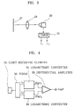
- Fig. 4 is a circuit diagram illustrating signal processor means comprising logarithmic converters 33, 34 and a differential amplifier 35.
- the one logarithmic converter 33 serves to convert the photoelectrically converted current I 1 output from the light receiver element 29 to corresponding voltage V 1 , utilizing suitable means and then to achieve logarithmic conversion of this voltage V 1 .
- the other logarithmic converter 34 serves to convert the photoelectrically converted current I 2 output from the light receiver element 29 to corresponding voltage V 2 and then to achieve logarithmic conversion of this voltage V 2 .
- the light components respectively projected along the optical paths 25, 26 having different lengths are alternately shielded, then a differential luminance on the object 27 illuminated by the light components projected along the respective optical paths 25, 26 is calculated as a difference in the intensities of these light components projected along the respective optical paths and then received by the light receiver element 29, and there a distance to the object 27 is determined.
- a convex lens 36 is placed in the optical path 25 relative to the light source 20 with a distance l 3 between the light source 20 and the convex lens 36 being smaller than a focal distance f of said convex lens 36 and the total reflection mirror 23 is placed in parallel to the half-mirror 21 so that one of the light components emitted from the light source 20 is projected by the half-mirror 21, the convex lens 36 and the liquid crystal plate 22 and the other light component is projected by the half-mirror 21, the total reflection mirror 23 and the liquid crystal plate 24. Also with such arrangement, it is possible to obtain a distance information from a differential intensity of the light components depending on a differential length of the optical paths.
- a virtual image 20A of the light source 20 serves as the apparent light source and the distance information can be obtained on the basis of this virtual image 20A.
- a light source 120 comprising LED a polarizing plate 121, a liquid crystal plate 122 of TN (Twisted Nematic) type, a polarizing beam splitter mirror 123 and a total reflection mirror 124.
- An additional total reflection mirror 126 is provided on a straight line extending between an object 125 to be gauged and said polarizing beam splitter mirror 123.
- the mirror 123 is spaced from the total reflection mirror 124 by l 1
- the total reflection mirror 124 is spaced from the total reflection mirror 126 by l 2
- the total reflection mirror 126 is spaced from the mirror 123 by l 3 .
- the light source 120 emits omnidirectional light which is incident on the polarizing plate 121 and output therefrom as polarized light 127 oscillating in a given direction. This polarized light 127 is then incident on the liquid crystal plate 122. If, at this moment, a switch 128 is at its opened position and therefore the liquid crystal plate 122 is not being energized from a power source 129, said polarized light 127 will have its direction rotated by an angle of 90° and thus the P-polarized light is output from said liquid crystal plate 122.
- the P-polarized light is transmitted through the mirror 123, then reflected on the total reflection mirrors 124, 126 and again transmitted through the mirror 123 to be projected onto the object 125.
- Such S-polarized light is reflected on the mirror 123 and then directly projected onto the object 125.
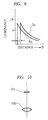
- the P-polarized light and the S-polarized light projected onto the object 125 have their characteristic curves Ep, Es plotted by a luminance on the object varying as function of a distance D, as shown by Fig. 9.
- a distance D to the object 125 can be determined on the basis of a ratio Ep/Es.
- a distance between the light source 120 and the polarizing beam splitter mirror 123 is extremely short compared to the distance D to the object 125 and may be regarded as zero in determination of the distance D.
- FIG. 10 there is schematically illustrated photoelectric converter means adapted to detect a luminance on the object 125 and convert this luminance to the corresponding electric signal.
- This photoelectric converter means comprises a condenser 130 and a light receiver element 131 so that the light reflected on the object 125 is condensed by the condenser 130 and incident on the light receiver element 131 which generates, in turn, an electric signal corresponding to a luminance on the object 125.
- Fig. 11 is a circuit diagram illustrating an example of the signal processor means comprising a square wave oscillator 132, a logarithmic converter 133, a separator 134 and a differential amplifier 135.
- the logarithmic converter 133 converts a photoelectrically converted current I output from the light receiver element 131 to the corresponding voltage V by use of suitable means and supplies the separator 134 with a signal Sc as shown by (c) of Fig. 12, which has been formed by log-compression of said voltage V.
- the separator 134 is supplied also from the square wave oscillator 132 with a timing signal Sa as shown by (a) of Fig. 12, with which the separator 134 operates to separates said log-compression signal Sc and thereby to generate signals Sd, Se as shown by (d) and (e), respectively, of Fig. 12.
- the signal Sa provided from the square wave oscillator 132 drives the power source 129, the liquid crystal plate 122 outputs the S-polarized light which is then received by the light receiver element 131, and the separator 134 is supplied with the log-compression signal Sc related to said S-polarized light and generates the signal Se.
- the liquid crystal plate 122 When the power source 129 is turned OFF as the signal Sa from the square wave oscillator 132 is lowered to zero level, the liquid crystal plate 122 outputs the P-polarized light which is then received by the light receiver element 131, and the separator 134 is supplied with the log-compression signal Sc related to the P-polarized light in response to which the separator 134 generates the signal Sd.
- the differential amplifier 135 includes an integrator adapted to integrate the respective signals Sd, Se output from the separator 134, and compares these integrated signals Sd, Se to form a differential signal thereof. In this manner, a distance D from the light source 120 to the object 125 can be determined on the basis of the difference between the respective signals Sd, Se, i.e., the ratio of the luminances on the object 125.
- the signals Sd, Se applied to the differential amplifier 135 often fail to exhibit the square waveform as shown in Fig. 12 particularly during rise-up time due to causes such as a delayed response of the liquid crystal plate 122 or the light receiver element 131.
- a stabilized portion of the waveform may be sample-held and processed without integration of the signals Sd, Se to obtain a desired distance information.
- the photoelectrically converted signals may be A/D converted and then digitally processed for the same purpose.
- a variant of the projector system in which the polarizing beam splitter mirror 123 is replaced by a prism 136 having a slant face 137 serving as a polarizing beam splitter so that only the P-polarized light component is transmitted therethrough but the S-polarized light component of the light incident on the slant face 137 is reflected thereon, and said P-polarized light component is then reflected on a concave mirror 138.
- concave mirror 138 is preferably hyperboloidal, a spherical mirror may be also useful so far as it functions so as to make a position of the light source remote from the P-polarized light component.
- the instant embodiment has been described above as the specific case in which the P-polarized light component and the S-polarized light component are incident on the light receiver element 131, the light reflected on the object 125 actually need not to be maintained polarized as said P- and S-polarized light components.
- the object may have also a reflecting surface comprising ordinary materials tending to disturb the polarized light.
- FIG. 14 there is illustrated another variant of the projector system in which the total reflection mirror 124 is placed in parallel to the polarizing beam splitter mirror 123 and a convex lens 139 is interposed between said mirror 123 and the object 125 so that the S-polarized light component is projected by the convex lens 139 onto the object 125 while the P-polarized light component is projected by the total reflection mirror 124 onto the object 125.
- the convex lens 139 should be positioned so as to set the light source of the S-polarized light component as a virtual image on a remote point.
Landscapes
- Engineering & Computer Science (AREA)
- Physics & Mathematics (AREA)
- Electromagnetism (AREA)
- Computer Networks & Wireless Communication (AREA)
- General Physics & Mathematics (AREA)
- Radar, Positioning & Navigation (AREA)
- Remote Sensing (AREA)
- Mechanical Engineering (AREA)
- Liquid Crystal (AREA)
- Measurement Of Optical Distance (AREA)
- Length Measuring Devices By Optical Means (AREA)
Description
- The present invention relates to an optical gauging apparatus utilizing the light reflected on an object to be gauged and being useful for gauging of, for example, car level, spring deflection and photographic distance.
- There have already been proposed various gauging apparatuses utilizing the light reflected on an object to be gauged, an example of which, i.e. Japanese Patent JP-A-4-40314, is schematically shown by Fig. 15 of the accompanying drawing.
- This example of prior art includes a pair of
point light sources object 13 to be gauged. - The light reflected on the
object 13 is incident on a light receiver 14 adapted to be exposed alternately to one light component emitted from the onelight source 11 and then reflected on theobject 13, on one hand, and another light component emitted from theother light source 12 and then reflected on theobject 13, on the other hand. The light receiver 14 generates photoelectric conversion signals Sp, Ss corresponding to quantities of the reflected light components derived from therespective light sources - With such optical gauging apparatus of well known art, the
object 13 has two different luminances Ep, Es based on the light components projected from therespective light sources object 13 correspond to KEp and KEs, respectively, where K represents a reflection factor of theobject 13. Accordingly, ratio of these surface luminances is expressed as follows:
object 13 can be determined by processing the photoelectric conversion signals Sp, Ss as functions of the distance. - The above-mentioned optical gauging apparatus of prior art is very advantageous in that the distance can be determined from the ratio of the surface luminances on the
object 13 regardless the reflection factor K of theobject 13, as will be apparently understood from said equation (1). - However, this apparatus of prior art uses a pair of
light sources light sources - No problem occurs so far as the intensities of the light components projected from these
light sources - It is a principal object of the present invention to solve said problem by improving the above-mentioned apparatus so as to make light projection from a single light source.
- One piece of prior art which uses a single light source is the pattern detector of JP-63-187102. In this document, the P and S components of a laser beam are separated and travel along different optical paths before being superposed. The beam resulting from the superposition of components is then reflected from the pattern to be gauged and converted into electrical signals, thereby to detect the position of the pattern.
- The present invention resides in an optical gauging apparatus comprising light emitter means for alternately emitting a pair of light components having different polarization characteristics; splitter means to split the pair of light components having been emitted from the light emitter means into a pair of different optical paths; projector means to project the light components having been split by said splitter means along a pair of optical paths having different lengths onto an object to be gauged; and signal processor means adapted for, upon reception of the light components reflected on the object and photoelectric conversion thereof, followed by time-division processing of the photoelectric conversion signals so as to provide a desired gauging information.
- With this gauging apparatus, the pair of light components having different polarization characteristics are emitted, these light components are then splitted into a pair of different optical paths, respectively, the light components thus split are projected along a pair of optical paths having different lengths onto the object to be gauged, and the light components reflected on the object are photoelectrically converted to the corresponding photoelectric conversion signals which are then time-division processed so as to provide a desired gauging information. This arrangement also realizes a gauging apparatus which is substantially free from a false result of gauging even when the intensity of light projected from the light source varies due to various causes such as deterioration thereof.
In the drawings - Fig. 1 is a schematic diagram showing projector means, splitter means and shield means arranged in an optical gauging apparatus which is not an embodiment of the present invention but which is useful in understanding the present invention;
- Fig. 2 is a waveform diagram illustrating the operation of the gauging apparatus of Fig. 1;
- Fig. 3 is a schematic diagram showing a light receiver system of the gauging apparatus of Fig. 1;
- Fig. 4 is a block diagram showing signal processor means of the gauging apparatus of Fig. 1;
- Fig. 5 is a schematic diagram showing a variant of the projector system;
- Fig. 6 is a schematic diagram showing another variant of the projector system;
- Fig. 7 is a schematic diagram showing light emitter means, splitter means and projector means arranged for an embodiment of the present invention;
- Fig. 8 is a schematic diagram illustrating how the splitter means and the projector means operates in this embodiment;
- Fig. 9 is a graphic diagram showing characteristic curves of luminances on an object to be gauged;
- Fig. 10 is a schematic diagram of photoelectric converter means in this embodiment;
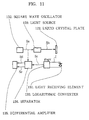
- Fig. 11 is a schematic diagram of signal processor means in this embodiment;
- Fig. 12 is a waveform diagram illustrating how the signal process means of this embodiment operates;
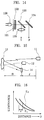
- Fig. 13 is a schematic diagram showing a variant of the projector system of gauging apparatus according to the present invention;
- Fig. 14 is a schematic diagram showing another variant of the projector system of gauging apparatus according the present invention;
- Fig. 15 is a schematic diagram showing by way of example the arrangement of prior art; and
- Fig. 16 is a graphic diagram showing characteristic curves of luminances on the object in this arrangement of prior art.
- An optical gauging apparatus which is not an embodiment of the present invention, but which is useful in understanding the present invention, will now be described with reference to Figs. 1 to 6 of the accompanying drawings.
- Referring to Fig. 1, projector means, splitter means and shield means are shown, wherein there are placed on an optical axis of a light source 20 a half-
mirror 21 and aliquid crystal plate 22, on one hand, and there are placed on a straight line extending in parallel to the optical axis of the light source 20 atotal reflection mirror 23 and anotherliquid crystal plate 24, on the other hand. - Light emitted from the
light source 20 which comprises LED is propagated by the half-mirror 21 and theliquid crystal plate 22 along anoptical path 25 and partially reflected on the half-mirror 21 so as to be directed to thetotal reflection mirror 23. - Specifically, the half-
mirror 21 is tilted with respect to theoptical path 25 so that the half-mirror 21 extends in parallel to thetotal reflection mirror 23. In a consequence, the light having been reflected on the half-mirror 21 is then reflected on thetotal reflection mirror 23 and then projected by theliquid crystal plate 24 along anoptical path 26. - It should be understood that the
total reflection mirror 23 is spaced from the half-mirror 21 by a distance l1 and there is a differential optical path length of l1 + l2 between theoptical paths - Meanwhile, the
liquid crystal plates liquid crystal plates liquid crystal plates - In response to such projection a light receiver system adapted to be exposed to the light components reflected on an
object 27 to be gauged outputs photoelectrically converted currents I1, I2 as illustrated by (c) of Fig. 2. - It should be understood that I1 is derived from the light propagated along the
optical path 25 and then reflected on theobject 27 while I2 is derived from the light component propagated along theoptical path 26 and then reflected on theobject 27. - The light component projected along the
optical path 26 has the intensity lower than the light component projected along theoptical path 25 because theoptical path 26 is longer than theoptical path 25. Correspondingly, the photoelectrically converted current I1 > the photoelectrically converted current I2. - Fig. 2 illustrates in (d) the phtoelectrically converted current output from the light receiver system when the system is provided only with the
liquid crystal plate 24. - With such arrangement, the
optical path 25 continues to propagate the associated light component projected onto theobject 27. Accordingly, the light receiver system receives only the light component projected along theoptical path 25 and reflected on theobject 27 when theliquid crystal plate 24 shields the associated light component, and receives the light component projected along both theoptical path object 27, resulting in the waveform as illustrated by (d) of Fig. 2. - Referring to Fig. 3, a light receiver system serving to determine luminances on the
object 27 is illustrated. - As will be apparent from Fig. 3, the light receiver system comprises a
condenser 28, alight receiver element 29 and atimer 30, wherein the light components having been reflected on theobject 27 are condensed by thecondenser 28 and the condensed light components are then received by thelight receiver element 29. - The
light receiver element 29 generates the photoelectrically converted currents I1, I2 corresponding to the quantities of the respective light components received thereby. More specifically, these phtoelectrically converted currents I1, I2 are output through thetimer 30 adapted to sort the signals in accordance with the actuation timing of theliquid crystal plates - Fig. 4 is a circuit diagram illustrating signal processor means comprising
logarithmic converters differential amplifier 35. - The one
logarithmic converter 33 serves to convert the photoelectrically converted current I1 output from thelight receiver element 29 to corresponding voltage V1, utilizing suitable means and then to achieve logarithmic conversion of this voltage V1. - Similarly, the other
logarithmic converter 34 serves to convert the photoelectrically converted current I2 output from thelight receiver element 29 to corresponding voltage V2 and then to achieve logarithmic conversion of this voltage V2. - The
differential amplifier 35 is supplied from the respectivelogarithmic converters - Said signal processor means operates to derive


- The light components respectively projected along the
optical paths object 27 illuminated by the light components projected along the respectiveoptical paths light receiver element 29, and there a distance to theobject 27 is determined. - It is possible to obtain such distance information from the differential intensity of the light components received by the light receiver element also when, as schematically illustrated by Fig. 5, there are provided the half-
mirror 21, amirror 23A and theliquid crystal plate 22 in theoptical path 25 while there are providedmirrors liquid crystal plate 24 in theoptical path 26 so that the light component having been reflected on the half-mirror 21 is projected by themirrors liquid crystal plate 24 onto theobject 27, so long as theliquid crystal plates optical paths - This is true also in an arrangement as schematically illustrated by Fig. 6. A
convex lens 36 is placed in theoptical path 25 relative to thelight source 20 with a distance l3 between thelight source 20 and theconvex lens 36 being smaller than a focal distance f of saidconvex lens 36 and thetotal reflection mirror 23 is placed in parallel to the half-mirror 21 so that one of the light components emitted from thelight source 20 is projected by the half-mirror 21, theconvex lens 36 and theliquid crystal plate 22 and the other light component is projected by the half-mirror 21, thetotal reflection mirror 23 and theliquid crystal plate 24. Also with such arrangement, it is possible to obtain a distance information from a differential intensity of the light components depending on a differential length of the optical paths. - A
virtual image 20A of thelight source 20 serves as the apparent light source and the distance information can be obtained on the basis of thisvirtual image 20A. - It is also possible to employ the signal processor means adapted to subject the photoelectric conversion signals to A/D conversion for a subsequent digital processing or the signal processor means adapted to make the signal processing by means of a divider.
- As will be apparent from (a) and (b) of Fig. 2, it is unnecessary that light transmission and light shielding by the one
liquid crystal plate 22 concur with light shielding and light transmission by the otherliquid crystal plate 24, respectively, because the present invention will be effectively implemented so long as operating modes of theseliquid crystal plates - An embodiment of the present invention will now be described with reference to Figs. 7 through 14 of the accompanying drawings.
- Referring to Fig. 7 showing light emitter means, splitter means and projector means, there are provided on an optical axis of a
light source 120 comprising LED apolarizing plate 121, aliquid crystal plate 122 of TN (Twisted Nematic) type, a polarizingbeam splitter mirror 123 and atotal reflection mirror 124. - An additional
total reflection mirror 126 is provided on a straight line extending between anobject 125 to be gauged and said polarizingbeam splitter mirror 123. Themirror 123 is spaced from thetotal reflection mirror 124 by l1, thetotal reflection mirror 124 is spaced from thetotal reflection mirror 126 by l2 and thetotal reflection mirror 126 is spaced from themirror 123 by l3. - Referring to Fig. 8, the
light source 120 emits omnidirectional light which is incident on thepolarizing plate 121 and output therefrom aspolarized light 127 oscillating in a given direction. Thispolarized light 127 is then incident on theliquid crystal plate 122. If, at this moment, aswitch 128 is at its opened position and therefore theliquid crystal plate 122 is not being energized from apower source 129, saidpolarized light 127 will have its direction rotated by an angle of 90° and thus the P-polarized light is output from saidliquid crystal plate 122. - The P-polarized light is transmitted through the
mirror 123, then reflected on the total reflection mirrors 124, 126 and again transmitted through themirror 123 to be projected onto theobject 125. - If, at said moment, the
switch 128 is at its closed position and therefore theliquid crystal plate 122 is being energized from thepower source 129, no rotation of the polarized light will occur because liquid crystal molecules of theliquid crystal plate 122 are aligned in the direction of the optical axis. As a result, the polarized light will be transmitted through theliquid crystal plate 122 as the S-polarized light. - Such S-polarized light is reflected on the
mirror 123 and then directly projected onto theobject 125. Regarding this, the optical path for the P-polarized light is longer than the optical path for S-polarized light by l = l1 + l2 + l3. - With a consequence, the P-polarized light and the S-polarized light projected onto the
object 125 have their characteristic curves Ep, Es plotted by a luminance on the object varying as function of a distance D, as shown by Fig. 9. - As will be understood from Fig. 9, a distance D to the
object 125 can be determined on the basis of a ratio Ep/Es. - It should be understood that a distance between the
light source 120 and the polarizingbeam splitter mirror 123 is extremely short compared to the distance D to theobject 125 and may be regarded as zero in determination of the distance D. - Referring to Fig. 10, there is schematically illustrated photoelectric converter means adapted to detect a luminance on the
object 125 and convert this luminance to the corresponding electric signal. - This photoelectric converter means comprises a
condenser 130 and alight receiver element 131 so that the light reflected on theobject 125 is condensed by thecondenser 130 and incident on thelight receiver element 131 which generates, in turn, an electric signal corresponding to a luminance on theobject 125. - Fig. 11 is a circuit diagram illustrating an example of the signal processor means comprising a
square wave oscillator 132, alogarithmic converter 133, aseparator 134 and adifferential amplifier 135. - The
logarithmic converter 133 converts a photoelectrically converted current I output from thelight receiver element 131 to the corresponding voltage V by use of suitable means and supplies theseparator 134 with a signal Sc as shown by (c) of Fig. 12, which has been formed by log-compression of said voltage V. - The
separator 134 is supplied also from thesquare wave oscillator 132 with a timing signal Sa as shown by (a) of Fig. 12, with which theseparator 134 operates to separates said log-compression signal Sc and thereby to generate signals Sd, Se as shown by (d) and (e), respectively, of Fig. 12. - More specifically, the signal Sa provided from the
square wave oscillator 132 drives thepower source 129, theliquid crystal plate 122 outputs the S-polarized light which is then received by thelight receiver element 131, and theseparator 134 is supplied with the log-compression signal Sc related to said S-polarized light and generates the signal Se. - When the
power source 129 is driven, a drive voltage Sb as shown by (b) of Fig. 12 is applied to theliquid crystal plate 122. - When the
power source 129 is turned OFF as the signal Sa from thesquare wave oscillator 132 is lowered to zero level, theliquid crystal plate 122 outputs the P-polarized light which is then received by thelight receiver element 131, and theseparator 134 is supplied with the log-compression signal Sc related to the P-polarized light in response to which theseparator 134 generates the signal Sd. - The
differential amplifier 135 includes an integrator adapted to integrate the respective signals Sd, Se output from theseparator 134, and compares these integrated signals Sd, Se to form a differential signal thereof. In this manner, a distance D from thelight source 120 to theobject 125 can be determined on the basis of the difference between the respective signals Sd, Se, i.e., the ratio of the luminances on theobject 125. - It should be noted here that the signals Sd, Se applied to the
differential amplifier 135 often fail to exhibit the square waveform as shown in Fig. 12 particularly during rise-up time due to causes such as a delayed response of theliquid crystal plate 122 or thelight receiver element 131. To overcome such inconvenience, a stabilized portion of the waveform may be sample-held and processed without integration of the signals Sd, Se to obtain a desired distance information. Alternatively, the photoelectrically converted signals may be A/D converted and then digitally processed for the same purpose. - Referring to Fig. 13, there is illustrated a variant of the projector system in which the polarizing
beam splitter mirror 123 is replaced by aprism 136 having aslant face 137 serving as a polarizing beam splitter so that only the P-polarized light component is transmitted therethrough but the S-polarized light component of the light incident on theslant face 137 is reflected thereon, and said P-polarized light component is then reflected on aconcave mirror 138. - While the
concave mirror 138 is preferably hyperboloidal, a spherical mirror may be also useful so far as it functions so as to make a position of the light source remote from the P-polarized light component. - Although the instant embodiment has been described above as the specific case in which the P-polarized light component and the S-polarized light component are incident on the
light receiver element 131, the light reflected on theobject 125 actually need not to be maintained polarized as said P- and S-polarized light components. In other words, the object may have also a reflecting surface comprising ordinary materials tending to disturb the polarized light. - Finally referring to Fig. 14, there is illustrated another variant of the projector system in which the
total reflection mirror 124 is placed in parallel to the polarizingbeam splitter mirror 123 and aconvex lens 139 is interposed between saidmirror 123 and theobject 125 so that the S-polarized light component is projected by theconvex lens 139 onto theobject 125 while the P-polarized light component is projected by thetotal reflection mirror 124 onto theobject 125. - The
convex lens 139 should be positioned so as to set the light source of the S-polarized light component as a virtual image on a remote point. - While the respective embodiments have been described hereinabove as utilizing the
polarizing plate 121, suchpolarizing plate 121 will be unnecessary when a light source emitting polarized light such as a laser source is employed as the light source.
Claims (6)
- An optical gauging apparatus comprising:light emitter means (120,121,122, 128,129,132) for alternately emitting two light components having different polarization characteristics;splitter means (123,137) to split the two light components emitted by said light emitter means into different optical path lengths;projector means (124, 126,136,138,139) to project the two light components which have been split by said splitter means to an object (125) to be gauged along different optical path lengths;photoelectric conversion means (130,131) for receiving and photoelectrically converting said two light components reflected by the object (125) to be gauged to generate a photoelectric conversion signal;signal dividing means (133,134) for dividing the photoelectric conversion signal into two signals by time-division processing, the time division of that processing corresponding to the timing of the alternately emitted light components from the light emitter means, and signal processor means (135) for calculating the difference between the two signals to provide an output of distance information of the object to be gauged.
- An optical gauging apparatus according to claim 1, wherein said light emitter means comprises a single light source (120), a polarising plate (121) and a liquid crystal plate (122) in the optical path of the light emitted therefrom; and wherein said light emitter means alternately emits a pair of light components having different polarisation characteristics under controlled energization of said liquid crystal plate (122).
- An optical gauging apparatus according to claim 1, wherein said splitter means comprises a polarising beam splitter mirror (123) placed in the optical path of the light emitted from the light emitter means so that said polarising beam splitter mirror (123) splits the light incident thereon into a polarised light component transmitted therethrough and a polarised light component reflected thereon.
- An optical gauging apparatus according to claim 1, wherein said splitter means comprises a polarising beam splitter mirror (123) placed in the optical path of the light emitted from the light emitter means so that said polarising beam splitter mirror (123) splits the light incident thereon into a polarised light component transmitted therethrough and a polarised light component reflected thereon; and wherein said projector means is adapted to direct said polarised light component having been transmitted through said polarising beam splitter mirror (123) to one or more total reflection mirrors (124,126) so that this polarised light component is reflected on said total reflection mirror(s) (124,126) so as to be projected in the same direction as the other polarised light component and thereby the pair of light components having different polarisation characteristics are projected along different optical paths, respectively.
- An optical gauging apparatus according to claim 1, wherein said splitter means comprises a polarising beam splitter mirror (137) placed in the optical path of the light emitted from the light emitter means so that said polarising beam splitter mirror (137) splits the light incident thereon into a polarised light component transmitted therethrough and a polarised light component reflected thereon; and wherein said projector means is adapted to direct said light having been transmitted therethrough said polarising beam splitter mirror (137) to a concave mirror (138) such as a hyperboloidal mirror so that this polarised light component is reflected on said concave mirror (138) so as to be projected in the same direction as the other polarised light component and thereby the pair of light components having different polarisation characteristics are projected along different optical paths, respectively.
- An optical gauging apparatus according to claim 1, wherein said splitter means comprises a polarising beam splitter mirror (123) placed in the optical path of the light emitted from the light emitter means so that said polarising beam splitter mirror (123) splits the light incident thereon into a polarised light component transmitted therethrough and a polarised light component reflected thereon; and wherein said projector means includes a convex lens (139) placed in the optical path of the polarised light component having been reflected on said polarising beam splitter mirror (123) so that the polarised light component having been transmitted through said convex lens (139) is reflected on a total reflection mirror (124) so as to be projected in the same direction as the other polarised light component having been transmitted through said polarising beam splitter mirror (123) and thereby the pair of light components having different polarisation characteristics are projected along different optical paths, respectively.
Applications Claiming Priority (4)
| Application Number | Priority Date | Filing Date | Title |
|---|---|---|---|
| JP210337/90 | 1990-08-10 | ||
| JP21033790A JPH0493706A (en) | 1990-08-10 | 1990-08-10 | Optical measuring apparatus |
| JP2220967A JPH0776699B2 (en) | 1990-08-24 | 1990-08-24 | Optical measuring device |
| JP220967/90 | 1990-08-24 |
Publications (3)
| Publication Number | Publication Date |
|---|---|
| EP0470825A2 EP0470825A2 (en) | 1992-02-12 |
| EP0470825A3 EP0470825A3 (en) | 1993-05-05 |
| EP0470825B1 true EP0470825B1 (en) | 1996-11-13 |
Family
ID=26517991
Family Applications (1)
| Application Number | Title | Priority Date | Filing Date |
|---|---|---|---|
| EP91307252A Expired - Lifetime EP0470825B1 (en) | 1990-08-10 | 1991-08-07 | Optical gauging apparatus |
Country Status (4)
| Country | Link |
|---|---|
| US (1) | US5149952A (en) |
| EP (1) | EP0470825B1 (en) |
| CA (1) | CA2048912A1 (en) |
| DE (1) | DE69123097T2 (en) |
Families Citing this family (6)
| Publication number | Priority date | Publication date | Assignee | Title |
|---|---|---|---|---|
| US5625196A (en) * | 1995-05-30 | 1997-04-29 | Abb Industrial Systems, Inc. | Method and apparatus for monitoring/calibrating a process measuring system |
| US7123351B1 (en) | 2002-08-20 | 2006-10-17 | Schaefer Philip R | Method and apparatus for measuring distances using light |
| US7221437B1 (en) * | 2002-08-20 | 2007-05-22 | Schaefer Philip R | Method and apparatus for measuring distances using light |
| US7684016B1 (en) | 2003-08-15 | 2010-03-23 | Schaefer Philip R | Method and apparatus for measuring distances using light |
| CN101762809B (en) * | 2009-12-29 | 2012-08-08 | 江苏徕兹光电科技有限公司 | Calibration method based on liquid crystal light valve principle phase position measurement, calibration device and distance measuring device |
| CN102426027B (en) * | 2011-09-05 | 2013-10-02 | 南京德朔实业有限公司 | Inner optical system control and switching apparatus for laser range finder |
Citations (1)
| Publication number | Priority date | Publication date | Assignee | Title |
|---|---|---|---|---|
| JPH0440314A (en) * | 1990-06-05 | 1992-02-10 | Stanley Electric Co Ltd | Optical measuring instrument |
Family Cites Families (5)
| Publication number | Priority date | Publication date | Assignee | Title |
|---|---|---|---|---|
| FR2222634A1 (en) * | 1973-03-21 | 1974-10-18 | Ibm | |
| US3937574A (en) * | 1973-10-29 | 1976-02-10 | Kaman Sciences Corporation | System and method for measuring distance |
| DE3039425A1 (en) * | 1980-10-18 | 1982-05-19 | Ernst Leitz Wetzlar Gmbh, 6330 Wetzlar | DEVICE FOR PHOTOELECTRICALLY DETERMINING THE POSITION OF AT LEAST ONE FOCUS OF AN IMAGE |
| US4888490A (en) * | 1988-05-24 | 1989-12-19 | University Of Southern California | Optical proximity apparatus and method using light sources being modulated at different frequencies |
| EP0419082B1 (en) * | 1989-09-21 | 1996-04-17 | Stanley Electric Corporation | Optical distance gauging apparatus |
-
1991
- 1991-07-19 US US07/732,636 patent/US5149952A/en not_active Expired - Fee Related
- 1991-08-07 DE DE69123097T patent/DE69123097T2/en not_active Expired - Fee Related
- 1991-08-07 EP EP91307252A patent/EP0470825B1/en not_active Expired - Lifetime
- 1991-08-09 CA CA002048912A patent/CA2048912A1/en not_active Abandoned
Patent Citations (1)
| Publication number | Priority date | Publication date | Assignee | Title |
|---|---|---|---|---|
| JPH0440314A (en) * | 1990-06-05 | 1992-02-10 | Stanley Electric Co Ltd | Optical measuring instrument |
Also Published As
| Publication number | Publication date |
|---|---|
| DE69123097T2 (en) | 1997-04-03 |
| DE69123097D1 (en) | 1996-12-19 |
| CA2048912A1 (en) | 1992-02-11 |
| EP0470825A3 (en) | 1993-05-05 |
| US5149952A (en) | 1992-09-22 |
| EP0470825A2 (en) | 1992-02-12 |
Similar Documents
| Publication | Publication Date | Title |
|---|---|---|
| EP0419082B1 (en) | Optical distance gauging apparatus | |
| US4490608A (en) | Position sensor | |
| EP0389240A3 (en) | Polarizing beam splitter apparatus and light valve image projection system | |
| US6388754B1 (en) | Shape measuring system and method | |
| WO1998052019A1 (en) | Ellipsometer with two lasers | |
| US5910841A (en) | Ellipsometer using an expanded beam | |
| US5293535A (en) | Eye direction detecting device | |
| US5149952A (en) | Optical gauging apparatus using dual beams and intermittent interruption | |
| US3552859A (en) | Optical instrument for determining the parallelism or nonparallelism of two reflecting surfaces | |
| US5317375A (en) | Optical distance measuring apparatus | |
| US5500754A (en) | Optical transmitter-receiver | |
| JP2824375B2 (en) | Optical delay circuit | |
| JPS56146359A (en) | Deflecting device of laser scan | |
| US3192825A (en) | Spectrally coded optical transmission of images | |
| JPS6064284A (en) | Laser distance measuring apparatus | |
| US3833302A (en) | Method and apparatus for the automatic photoelectric trapping of local changes of optically effective object structures | |
| US3623809A (en) | Optical system with polarizing filters for line follower head | |
| SU616852A1 (en) | Discrete optical level-flow gauge | |
| JP3096795B2 (en) | Tracking ranging system | |
| JPH0493706A (en) | Optical measuring apparatus | |
| JPS5948668A (en) | Optical fiber speedometer | |
| JPS61126524A (en) | Adjusting device for quantity of laser light | |
| JP2920306B2 (en) | Remote information transmission device | |
| GB2256764A (en) | Laser system with heterodyne detection | |
| JPH0776699B2 (en) | Optical measuring device |
Legal Events
| Date | Code | Title | Description |
|---|---|---|---|
| PUAI | Public reference made under article 153(3) epc to a published international application that has entered the european phase |
Free format text: ORIGINAL CODE: 0009012 |
|
| AK | Designated contracting states |
Kind code of ref document: A2 Designated state(s): DE FR GB |
|
| PUAL | Search report despatched |
Free format text: ORIGINAL CODE: 0009013 |
|
| AK | Designated contracting states |
Kind code of ref document: A3 Designated state(s): DE FR GB |
|
| 17P | Request for examination filed |
Effective date: 19931015 |
|
| 17Q | First examination report despatched |
Effective date: 19940706 |
|
| GRAG | Despatch of communication of intention to grant |
Free format text: ORIGINAL CODE: EPIDOS AGRA |
|
| GRAH | Despatch of communication of intention to grant a patent |
Free format text: ORIGINAL CODE: EPIDOS IGRA |
|
| GRAH | Despatch of communication of intention to grant a patent |
Free format text: ORIGINAL CODE: EPIDOS IGRA |
|
| GRAA | (expected) grant |
Free format text: ORIGINAL CODE: 0009210 |
|
| AK | Designated contracting states |
Kind code of ref document: B1 Designated state(s): DE FR GB |
|
| REF | Corresponds to: |
Ref document number: 69123097 Country of ref document: DE Date of ref document: 19961219 |
|
| ET | Fr: translation filed | ||
| PLBE | No opposition filed within time limit |
Free format text: ORIGINAL CODE: 0009261 |
|
| STAA | Information on the status of an ep patent application or granted ep patent |
Free format text: STATUS: NO OPPOSITION FILED WITHIN TIME LIMIT |
|
| 26N | No opposition filed | ||
| PGFP | Annual fee paid to national office [announced via postgrant information from national office to epo] |
Ref country code: GB Payment date: 19990728 Year of fee payment: 9 |
|
| PGFP | Annual fee paid to national office [announced via postgrant information from national office to epo] |
Ref country code: FR Payment date: 19990818 Year of fee payment: 9 |
|
| PGFP | Annual fee paid to national office [announced via postgrant information from national office to epo] |
Ref country code: DE Payment date: 19990820 Year of fee payment: 9 |
|
| PG25 | Lapsed in a contracting state [announced via postgrant information from national office to epo] |
Ref country code: GB Free format text: LAPSE BECAUSE OF NON-PAYMENT OF DUE FEES Effective date: 20000807 |
|
| GBPC | Gb: european patent ceased through non-payment of renewal fee |
Effective date: 20000807 |
|
| PG25 | Lapsed in a contracting state [announced via postgrant information from national office to epo] |
Ref country code: FR Free format text: LAPSE BECAUSE OF NON-PAYMENT OF DUE FEES Effective date: 20010430 |
|
| PG25 | Lapsed in a contracting state [announced via postgrant information from national office to epo] |
Ref country code: DE Free format text: LAPSE BECAUSE OF NON-PAYMENT OF DUE FEES Effective date: 20010501 |
|
| REG | Reference to a national code |
Ref country code: FR Ref legal event code: ST |