EP0470532A1 - Verfahren zum Verdampfen von flüssigem Erdgas - Google Patents
Verfahren zum Verdampfen von flüssigem Erdgas Download PDFInfo
- Publication number
- EP0470532A1 EP0470532A1 EP91113073A EP91113073A EP0470532A1 EP 0470532 A1 EP0470532 A1 EP 0470532A1 EP 91113073 A EP91113073 A EP 91113073A EP 91113073 A EP91113073 A EP 91113073A EP 0470532 A1 EP0470532 A1 EP 0470532A1
- Authority
- EP
- European Patent Office
- Prior art keywords
- natural gas
- fluid
- circuit
- heat exchange
- stage
- Prior art date
- Legal status (The legal status is an assumption and is not a legal conclusion. Google has not performed a legal analysis and makes no representation as to the accuracy of the status listed.)
- Granted
Links
- 238000000034 method Methods 0.000 title claims abstract description 60
- 239000003949 liquefied natural gas Substances 0.000 title claims abstract description 22
- VNWKTOKETHGBQD-UHFFFAOYSA-N methane Chemical compound C VNWKTOKETHGBQD-UHFFFAOYSA-N 0.000 claims abstract description 122
- 239000012530 fluid Substances 0.000 claims abstract description 85
- 239000003345 natural gas Substances 0.000 claims abstract description 61
- 238000009833 condensation Methods 0.000 claims description 34
- 230000005494 condensation Effects 0.000 claims description 34
- 238000010438 heat treatment Methods 0.000 claims description 28
- 239000000203 mixture Substances 0.000 claims description 13
- 229930195733 hydrocarbon Natural products 0.000 claims description 10
- 238000001704 evaporation Methods 0.000 claims description 8
- 239000004215 Carbon black (E152) Substances 0.000 claims description 7
- -1 C 6 hydrocarbons Chemical class 0.000 claims description 5
- 150000002430 hydrocarbons Chemical class 0.000 claims description 5
- QGZKDVFQNNGYKY-UHFFFAOYSA-N Ammonia Chemical compound N QGZKDVFQNNGYKY-UHFFFAOYSA-N 0.000 claims description 4
- ATUOYWHBWRKTHZ-UHFFFAOYSA-N Propane Chemical compound CCC ATUOYWHBWRKTHZ-UHFFFAOYSA-N 0.000 claims description 4
- 239000007788 liquid Substances 0.000 claims description 4
- 238000012546 transfer Methods 0.000 claims description 4
- 230000004087 circulation Effects 0.000 claims description 3
- 239000000126 substance Substances 0.000 claims description 3
- OTMSDBZUPAUEDD-UHFFFAOYSA-N Ethane Chemical compound CC OTMSDBZUPAUEDD-UHFFFAOYSA-N 0.000 claims description 2
- 229910021529 ammonia Inorganic materials 0.000 claims description 2
- 239000001294 propane Substances 0.000 claims description 2
- XLYOFNOQVPJJNP-UHFFFAOYSA-N water Substances O XLYOFNOQVPJJNP-UHFFFAOYSA-N 0.000 claims description 2
- KYKAJFCTULSVSH-UHFFFAOYSA-N chloro(fluoro)methane Chemical compound F[C]Cl KYKAJFCTULSVSH-UHFFFAOYSA-N 0.000 claims 1
- 238000011084 recovery Methods 0.000 abstract description 3
- 230000015572 biosynthetic process Effects 0.000 abstract 1
- 230000008020 evaporation Effects 0.000 description 4
- 230000002349 favourable effect Effects 0.000 description 4
- 230000008016 vaporization Effects 0.000 description 4
- 230000006835 compression Effects 0.000 description 3
- 238000007906 compression Methods 0.000 description 3
- 239000007789 gas Substances 0.000 description 3
- 238000011161 development Methods 0.000 description 2
- 238000009834 vaporization Methods 0.000 description 2
- 125000004432 carbon atom Chemical group C* 0.000 description 1
- 238000013461 design Methods 0.000 description 1
- 238000005516 engineering process Methods 0.000 description 1
- 238000012986 modification Methods 0.000 description 1
- 230000004048 modification Effects 0.000 description 1
- 230000000717 retained effect Effects 0.000 description 1
Images
Classifications
-
- F—MECHANICAL ENGINEERING; LIGHTING; HEATING; WEAPONS; BLASTING
- F17—STORING OR DISTRIBUTING GASES OR LIQUIDS
- F17C—VESSELS FOR CONTAINING OR STORING COMPRESSED, LIQUEFIED OR SOLIDIFIED GASES; FIXED-CAPACITY GAS-HOLDERS; FILLING VESSELS WITH, OR DISCHARGING FROM VESSELS, COMPRESSED, LIQUEFIED, OR SOLIDIFIED GASES
- F17C9/00—Methods or apparatus for discharging liquefied or solidified gases from vessels not under pressure
- F17C9/02—Methods or apparatus for discharging liquefied or solidified gases from vessels not under pressure with change of state, e.g. vaporisation
- F17C9/04—Recovery of thermal energy
-
- F—MECHANICAL ENGINEERING; LIGHTING; HEATING; WEAPONS; BLASTING
- F17—STORING OR DISTRIBUTING GASES OR LIQUIDS
- F17C—VESSELS FOR CONTAINING OR STORING COMPRESSED, LIQUEFIED OR SOLIDIFIED GASES; FIXED-CAPACITY GAS-HOLDERS; FILLING VESSELS WITH, OR DISCHARGING FROM VESSELS, COMPRESSED, LIQUEFIED, OR SOLIDIFIED GASES
- F17C9/00—Methods or apparatus for discharging liquefied or solidified gases from vessels not under pressure
- F17C9/02—Methods or apparatus for discharging liquefied or solidified gases from vessels not under pressure with change of state, e.g. vaporisation
-
- F—MECHANICAL ENGINEERING; LIGHTING; HEATING; WEAPONS; BLASTING
- F01—MACHINES OR ENGINES IN GENERAL; ENGINE PLANTS IN GENERAL; STEAM ENGINES
- F01K—STEAM ENGINE PLANTS; STEAM ACCUMULATORS; ENGINE PLANTS NOT OTHERWISE PROVIDED FOR; ENGINES USING SPECIAL WORKING FLUIDS OR CYCLES
- F01K25/00—Plants or engines characterised by use of special working fluids, not otherwise provided for; Plants operating in closed cycles and not otherwise provided for
- F01K25/08—Plants or engines characterised by use of special working fluids, not otherwise provided for; Plants operating in closed cycles and not otherwise provided for using special vapours
- F01K25/10—Plants or engines characterised by use of special working fluids, not otherwise provided for; Plants operating in closed cycles and not otherwise provided for using special vapours the vapours being cold, e.g. ammonia, carbon dioxide, ether
-
- F—MECHANICAL ENGINEERING; LIGHTING; HEATING; WEAPONS; BLASTING
- F17—STORING OR DISTRIBUTING GASES OR LIQUIDS
- F17C—VESSELS FOR CONTAINING OR STORING COMPRESSED, LIQUEFIED OR SOLIDIFIED GASES; FIXED-CAPACITY GAS-HOLDERS; FILLING VESSELS WITH, OR DISCHARGING FROM VESSELS, COMPRESSED, LIQUEFIED, OR SOLIDIFIED GASES
- F17C2265/00—Effects achieved by gas storage or gas handling
- F17C2265/05—Regasification
Definitions
- the invention relates to a method for vaporizing liquid, pressurized natural gas with energy generation by heating and vaporizing the liquid natural gas in a multi-stage heat exchange with fluids which are conducted in separate circuits, the fluid being used for a first circuit and a part of the temperature which has been warmed to ambient temperature Natural gas is branched off, relieved of work, condensed in the heat exchange with liquid natural gas, pumped to the pressure level of the liquid gas and mixed with the natural gas to be warmed up again.
- the present invention was therefore based on the object of developing the method of the type mentioned at the outset in such a way that a lower investment cost, combined with an equally good or even better energy recovery, is ensured.
- This object is achieved in that the fluid of the first circuit is divided into partial flows after the work-related relaxation and condensation, one of which compresses to the pressure of the natural gas to be evaporated and the second parallel to, but separate from, the natural gas to be evaporated all heat exchange stages are carried out, evaporated, warmed and then released.
- the fluid of the first circuit ie natural gas warmed to ambient temperature
- the fluid of the first circuit is expanded to the desired delivery pressure in the process according to the invention and then condensed against liquid natural gas to be heated.
- a partial stream of the fluid is compressed to the pressure of the liquid natural gas stream and admixed to it again.
- the other partial flow is evaporated and warmed up again parallel to the path of the natural gas flow and drawn off as a separate product gas flow.
- the partial flow is expediently drawn off after the condensation of the fluid, since the composition of the product flow is only equal to the composition of the liquid natural gas fed into the system in the event of strongly fluctuating operating conditions.
- the amount of fluid diverted from the vaporized natural gas flow depends on the desired amount of product gas that is to be released at a lower pressure level than the liquid natural gas feed stream.
- product streams of different pressures can advantageously be generated in a system without increasing the number of system components involved in the method compared to the prior art.
- a plurality of product streams can also be generated at different pressure levels, for which purpose the fluid of the first circuit is expanded in a multi-stage, work-performing manner.
- the multi-stage work-relieving relaxation can be carried out by expansion machines connected in series as well as with units operated in parallel. If the expansion machines are connected in series, at least some of the already reduced pressure fluid is further expanded. If the expansion machines are connected in parallel, the fluid is distributed to branch flows, each of which is expanded to different pressure levels.
- parallel and serial modes of operation of the expansion machines can also be combined with one another.
- the multi-stage work relaxation is carried out by distributing the fluid of the first circuit before its work relaxation to branch streams, each of which is relaxed for work and condensed in different condensation stages, whereupon a partial stream is branched off and parallel to the path of the natural gas to be heated is heated and withdrawn.
- Partial streams are relaxed in all work-relieving relaxed streams, rather there is the possibility that a partial stream is not branched off after each condensation stage and evaporated, heated and released in parallel with the natural gas to be evaporated. If, for example, provision is made to relax the fluid of the first circuit in a two-stage manner, it is possible, depending on the process specifications, to generate one or two substreams at a lower pressure level. The generation of only one partial stream implies that the second branch stream is completely mixed again with the natural gas to be evaporated after its condensation.
- the fluid of the first circuit is expanded in a one-stage work-performing manner.
- this procedure contains an advantageous aspect.
- the further treatment of the work-relieved relaxed fluid of the first circuit can be chosen such that branch streams branched on partial streams are omitted, while only the branch stream to be completely mixed again with the natural gas to be evaporated is retained after its condensation.
- a fluid is conducted in a second circuit, which is relaxed in a one-stage work-performing manner after heating to ambient temperature in order to obtain energy.
- This embodiment of the method according to the invention can also be modified in that a fluid is conducted in a second circuit which, after it has warmed up to ambient temperature, is broken down into partial streams which are expanded to produce energy and work.
- mixture circuits are particularly favorable. It is proposed to use a C, / C2 / Ca hydrocarbon mixture or a C 1 / C 2 hydrocarbon mixture or a C 2 / C 3 hydrocarbon mixture as the fluid of the second circuit.
- C 1 to C 6 hydrocarbons are also particularly favorable to use a mixture of C 1 to C 6 hydrocarbons as the fluid of the second circuit, the C 2 content being less than 90 mol%.
- the designations C 1 to C 6 denote hydrocarbons with one to six carbon atoms.
- the selection of the heat-exchanging fluid of the second circuit depends on the composition of the natural gas stream to be evaporated in order to make the thermal contact between the streams particularly efficient and to provide the greatest possible energy for work-related relaxation.
- Pure substances can also be used as fluids of the second circuit.
- ammonia, propane or chlorofluorocarbons can be used favorably. In the latter case, there is also the possibility of mixing different chlorofluorocarbons for the fluid.
- the fluid of the further circuit is advantageously expanded in a single stage or, with particular preference, also in a multi-stage work-performing manner.
- Every process for the vaporization of liquid natural gas with simultaneous energy generation is based on the principle of extracting the required energy in the form of heat from a heating medium that participates in the heat exchange at the highest temperature level. It is particularly favorable for the invention if the circulation fluids are heated to ambient temperature in the last heat exchange stage by heat exchange with a glycol-water solution.
- the number of those separated from each other is Circulations limited to the first fluid circuit and the circuit of the heating medium.
- a further embodiment of the method according to the invention provides that the fluids of the second and / or third circuit after their condensation against natural gas to be warmed up and pumps to elevated pressure, in whole or in part, around the condensation stage corresponding to the pressure level and only at the next higher heat exchange stage at the heat transfer participate.
- the device used to carry out the method consists of heat exchange / condensation stages, at different temperature levels for the heat exchange of the circulating fluids with the natural gas to be evaporated, at least one heating stage in which the natural gas and the circulating fluids are heated to the highest process temperature against a heating medium, expansion machines for work relaxation and pumps for the recompression of the fluids condensed during heat exchange.
- the heat exchange / condensation stages it is particularly favorable to design the heat exchange / condensation stages as straight tube heat exchangers with multiple tube paths or bundles, or as wound tube heat exchangers with multiple tube paths.
- Another option is to use straight tube heat exchangers with only one tube path. In this case, several of these heat exchangers are connected in parallel for each heat exchange / condensation stage.
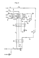
- FIG. 1 shows the execution of the method according to the invention, in which a second fluid circuit is used in addition to the heating circuit and the first circuit.
- a liquid, pressurized natural gas stream 1 is heated in a heat exchanger E1 against condensing natural gas from line 2b.
- this liquid natural gas stream can be composed of individual streams which are brought to a common high pressure.
- heat exchanger E2 the natural gas stream to be evaporated is further heated against the fluid of a second circuit which is conducted in the circuit of lines 3a, 3b and 3c.
- the final heating of the natural gas is carried out in heat exchanger H3A in counterflow to the heating medium to be cooled from line 4.
- a part is drawn off from the gaseous natural gas stream 1 warmed to ambient temperature via a branch line 2a, expanded in a work-performing manner in the expansion machine X1 and condensed in the heat exchanger / condensation stage E1.
- a partial stream 2c intended for delivery is separated and heated and evaporated in the heat exchangers E1, E2 and H3B parallel to the natural gas path.
- This partial flow forms the natural gas low-pressure product.
- the remaining condensed natural gas in line 2b is, as in the known method, compressed by means of pump P1 and mixed with the liquid natural gas stream 1 to be evaporated.
- the fluid of the second circuit draws its energy for work performance and natural gas heating from the heating medium provided in line 4.
- the fluid of the second circuit After passing through the heat exchanger H3C, the fluid of the second circuit has evaporated and is fed through the line 3a to the expansion turbine X2 and expanded to perform work.
- the resulting pressure-reduced stream 3b is then condensed in heat exchanger E2 against condensed pressure-increased fluid of the second circuit, the natural gas stream to be heated in line 1 and the natural gas low-pressure product stream to be heated in parallel, and brought to increased pressure again by means of pump P2.
- the medium used to heat the fluids to the highest process temperature is fed via line 4, and through the parallel connected heat exchangers H3A (in thermal contact with the natural gas to be vaporized under high pressure), H3B (in thermal contact with the low-pressure product to be heated) and heat exchanger H3C (in thermal contact with fluid to be evaporated from the second circuit) and drawn off after the heat removal via line 5.
- H3A in thermal contact with the natural gas to be vaporized under high pressure
- H3B in thermal contact with the low-pressure product to be heated
- heat exchanger H3C in thermal contact with fluid to be evaporated from the second circuit
- the method according to the invention provides significant advantages compared to the simplest method variant of DE-OS 38 36 061. While the method according to the invention manages with only one evaporation system, in a method according to the state of the art Technology two separate systems can be used. The machine effort is halved accordingly by using the invention.
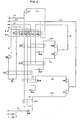
- FIG. 2 shows an embodiment of the method according to the invention, in which two circulating fluids are expanded in a multi-stage work-performing manner.
- natural gas flows which have different admission pressures, are brought to a common increased pressure and fed to the natural gas evaporation plant in the common line 1.
- This common current is in gradual thermal contact with the heat exchange fluids of the individual circuits are heated and evaporated.
- Part of the high-pressure product formed is drawn off in line 2c, while the remaining part is relaxed in the expansion machine X4 while performing work.
- the pressure-reduced product formed in line 2b is then heated to ambient temperature in heat exchanger H3E against heating fluid.
- Part of this product is drawn off via line 2b ', while the part which is discharged via line 2a forms the fluid of the first circuit.
- the fluid stream 2a is divided into the branch streams 3a and 3b for energy generation and these streams are expanded in the expansion machines X1B and X1A to different pressure levels while performing work.
- the relaxed branch flow 3a is condensed in heat exchanger E1A against liquid natural gas to be heated in line 1. After the condensation, a partial stream at reduced pressure is drawn off and heated and evaporated parallel to the remaining natural gas path and drawn off as a product in line 4. The rest of the condensed portion is compressed to the natural gas pressure by means of pump P1A and mixed again with the liquid natural gas before it passes through the first heat exchanger.
- the relaxed branch flow 3b is carried out in an analogous manner, the heat exchange or condensation in heat exchanger E1 B of the flows taking place at a higher temperature / heat exchange level.
- each pressure level corresponds to a heat exchange / condensation level of the fluid assigned to it.
- the heat exchange stage at the lowest temperature level must be used, while with increasing pressure, the condensation / heat exchange stages can be charged at a higher temperature level.
- the fluid of the second circuit is also expanded in a two-stage work-performing manner by distributing the evaporated fluid stream 6 leaving the heating stage H3D to branch streams 6a and 6b. These are brought to different pressures by means of expansion machines X2A and X2B, condensed according to their pressure level in the condensation stages E2A and E2B against natural gas and fluid to be heated and mixed again after compression to a common pressure in the pumps P2A and P2B.
- the fluid of the third circuit 7 is expanded in a one-stage work-performing manner using expansion machine X3 and is condensed in condensation stage E3 against natural gas of different pressures. After compression in P3 to the outlet pressure and passing through heat exchange stages E3 and H3F, the cycle closes. Analogous to the first two circuit fluids, the fluid of the third circuit can be expanded in several stages.
- the heat required for energy generation and vaporization of natural gas comes from a heating circuit, which is indicated by lines 8 and 9.
- the warm heating medium 8 is distributed to the heating stages H3A to H3F and releases its heat there to the vaporized natural gas product streams of different pressures and the fluids of the first to third circuits.
- the cooled heating medium is drawn off via line 9.
Landscapes
- Engineering & Computer Science (AREA)
- Mechanical Engineering (AREA)
- General Engineering & Computer Science (AREA)
- Chemical & Material Sciences (AREA)
- Combustion & Propulsion (AREA)
- Filling Or Discharging Of Gas Storage Vessels (AREA)
- Physical Or Chemical Processes And Apparatus (AREA)
- Vaporization, Distillation, Condensation, Sublimation, And Cold Traps (AREA)
- Exhaust Gas After Treatment (AREA)
- Separation By Low-Temperature Treatments (AREA)
Abstract
Description
- Die Erfindung betrifft ein Verfahren zum Verdampfen von flüssigem, unter Druck stehendem Erdgas mit Energiegewinnung, indem das flüssige Erdgas in mehrstufigem Wärmetausch mit, in voneinander getrennten Kreisläufen geführten Fluiden angewärmt und verdampft wird, wobei als Fluid für einen ersten Kreislauf ein Teil des auf Umgebungstemperatur angewärmten Erdgases abgezweigt, arbeitsleistend entspannt, im Wärmetausch mit flüssigem Erdgas kondensiert, auf das Druckniveau des flüssigen Ergases gepumpt und dem anzuwärmenden Erdgas wieder zugemischt wird.
- Aus der deutschen Anmeldung DE-OS 38 36 061 ist ein Verfahren zum Verdampfen von flüssigem Erdgas bekannt. Dort wird als Fluid des ersten Kreislaufes verdampftes und auf Umgebungstemperatur angewärmtes Erdgas verwendet. Dazu wird ein Teilstrom des Erdgases arbeitsleistend entspannt, im Wärmetausch mit flüssigem Erdgas kondensiert und nach Verdichtung auf den Druck des Erdgasstromes dem flüssigen Erdgas zur erneuten Verdampfung wieder zugespeist. In zumindest einem weiteren, getrennten Kreislauf wird ein Fluid geführt, welches im Wärmetausch mit einem Heizmedium verdampft, arbeitsleistend entspannt, gegen anzuwärmendes Erdgas kondensiert und vor seiner erneuten Verdampfung auf erhöhten Druck komprimiert wird.
- Sollen beim bekannten Verfahren jedoch Erdgasströme unterschiedlichen Druckes bearbeitet und abgegeben werden, so ist notwendig für jedes gewünschte Druckniveau eine getrennte Anlage zur Verfügung zu stellen. Dadurch erhöht sich die Gesamtzahl der einzusetzenden Anlagenbauteile, was eine Erhöhung des Investitionskostenaufwandes mit sich bringt.
- Der vorliegenden Erfindung lag daher die Aufgabe zugrunde, das Verfahren der eingangs genannten Art so weiterzubilden, daß ein geringerer Investitionskostenaufwand, verbunden mit einer gleich guten oder sogar besseren Energierückgewinnung gewährleistet ist.
- Diese Aufgabe wird erfindungsgemäß dadurch gelöst, daß das Fluid des ersten Kreislaufes nach der arbeitsleistenden Entspannung und Kondensation in Teilströme aufgeteilt wird, wovon der eine auf den Druck des zu verdampfenden Erdgases komprimiert und der zweite parallel zum zu verdampfenden Erdgas, aber getrennt von diesem, durch sämtliche Wärmetauschstufen geführt, dabei verdampft, angewärmt und danach abgegeben wird.
- Das Fluid des ersten Kreislaufes, also auf Umgebungstemperatur angewärmtes Erdgas, wird beim erfindungsgemäßen Verfahren auf den gewünschten Abgabedruck entspannt und danach gegen anzuwärmendes flüssiges Erdgas kondensiert. Ein Teilstrom des Fluids wird, wie im bekannten Verfahren, auf den Druck des flüssigen Erdgasstromes komprimiert und diesem wieder zugemischt. Der weitere Teilstrom dagegen wird parallel zum Weg des Erdgasstromes erneut verdampft und angewärmt und als getrennter Produktgasstrom abgezogen. Der Abzug des Teilstromes erfolgt zweckmäßigerweise nach der Kondensation des Fluids, da nur so bei stark schwankenden Betriebsbedingungen die Zusammensetzung des Produktstromes gleich der Zusammensetzung des in die Anlage gespeisten flüssigen Erdgases ist.
- Die aus dem verdampften Erdgasstrom abgezweigte Fluidmenge richtet sich hierbei nach der gewünschten Produktgasmenge, die auf einem niedrigeren Druckniveau als der flüssige Erdgaseinsatzstrom abgegeben werden soll.
- Mit dem erfindungsgemäßen Verfahren lassen sich auch flüssige Erdgasströme unterschiedlichen Eingangsdruckes verarbeiten, indem sie auf einen gemeinsamen hohen Druck gebracht werden und der Gesamtstrom im Wärmetausch mit Fluiden mehrerer Kreisläufe verdampft wird.
- Durch Anwendung des erfindungsgemäßen Verfahrens können vorteilhaft in einer Anlage Produktströme unterschiedlichen Druckes erzeugt werden, ohne die Anzahl der am Verfahren beteiligten Anlagenbauteile gegenüber dem Stand der Technik zu erhöhen.
- In Ausgestaltung der Erfindung können auch mehrere Produktströme auf unterschiedlichem Druckniveau erzeugt werden, wofür das Fluid des ersten Kreislaufes mehrstufig arbeitsleistend entspannt wird. Die mehrstufige arbeitsleistende Entspannung kann dabei sowohl durch in Reihe geschaltete Expansionsmaschinen erfolgen, wie auch mit parallel betriebenen Aggregaten durchgeführt werden. Sind die Expansionsmaschinen in Reihe geschaltet, wird zumindest ein Teil des bereits druckreduzierten Fluides weiter entspannt. Werden die Expansionsmaschinen parallel geschaltet, so wird das Fluid auf Zweigströme verteilt, die jeder für sich auf verschiedene Druckniveaus entspannt werden. Beim erfindungsgemäßen Verfahren können auch parallele und serielle Betriebsweisen der Expansionsmaschinen miteinander kombiniert werden.
- In einer besonders bevorzugten Verfahrensvariante wird die mehrstufige arbeitsleistende Entspannung durchgeführt, indem das Fluid des ersten Kreislaufes vor seiner arbeitsleistenden Entspannung auf Zweigströme verteilt wird, von denen jeder für sich arbeitsleistend entspannt und in unterschiedlichen Kondensationsstufen kondensiert wird, woraufhin jeweils ein Teilstrom abgezweigt und parallel zum Weg des anzuwärmenden Erdgases erwärmt und abgezogen wird.
- Bei der Abwandlung des erfindungsgemäßen Verfahrens ist es keineswegs notwendig, daß von allen arbeitsleistend entspannten Zweigströmen Teilströme abgetrennt werden, vielmehr besteht die Möglichkeit, daß nicht nach jeder Kondensationsstufe ein Teilstrom abgezweigt und parallel zum zu verdampfenden Erdgas verdampft, angewärmt und abgegeben wird. Ist beispielsweise vorgesehen, das Fluid des ersten Kreislaufes zweistufig arbeitsleistend zu entspannen, so ist, je nach den Verfahrensvorgaben, die Erzeugung eines oder zweier Teilströme auf niedrigerem Druckniveau möglich. Die Erzeugung nur eines Teilstromes impliziert, daß der zweite Zweigstrom nach seiner Kondensation dem zu verdampfenden Erdgas vollständig wieder zugemischt wird.
- Diese vorgenannten erfindungsgemäßen Maßnahmen bieten den Vorteil mehrere Erdgasströme unterschiedlichen Druckes in einer Anlage zu erzeugen. Es werden zwar mehr Expansionsturbinen eingesetzt als im einfachsten erfindungsgemäßen Fall, doch es wird die Effizienz des Verfahrens durch feiner abstufbare Wärmeübergänge und vermehrte Energierückgewinnung gesteigert. Gegenüber dem Grundprinzip der Erfindung sieht diese Weiterbildung vor, zunächst Zweigströme des ersten Fluides zu bilden und diese getrennt arbeitsleistend zu entspannen. Die Entspannung erfolgt dabei auf unterschiedliche Druckniveaus, wodurch für die Kondensation der jeweiligen Ströme unterschiedliche Kondensationsstufen, d.h. Wärmetauschstufen, benötigt werden. Dieses Vorgehen hat den Vorteil, daß der flüssige, zu verdampfende Erdgasstrom durch verfahrensgünstig fein abgestuften indirekten Wärmeaustausch angewärmt und verdampft wird.
- In Weiterbildung der Erfindung wird das Fluid des ersten Kreislaufes einstufig arbeitsleistend entspannt.
- Als Sonderfall der mehrstufigen Entspannung beinhaltet dieses Vorgehen einen vorteilhaften Aspekt. Die weitere Behandlung des arbeitsleistend entspannten Fluids des ersten Kreislaufes kann dahingehend gewählt werden, daß auf Teilsträme verzweigte Zweigströme entfallen, während nurmehr der nach seiner Kondensation vollständig dem zu verdampfenden Erdgas wieder zuzumischende Zweigstrom erhalten bleibt.
- Das geschilderte Vorgehen stellt nur einen besonders bevorzugten Spezialfall der Möglichkeiten der mehrstufigen Entspannung dar. In gleicher Weise wie mit den in paralleler arbeitsleistender Entspannung gewonnenen Zweigströmen kann mit den in serieller Betriebsweise erzeugten Zweigströmen verfahren werden, da die Erfindung auf alle mehrstufig arbeitsleistend entspannten Fluidströme anwendbar ist.
- Parallel zum ersten Fluidkreislauf wird, in einem zweiten Kreislauf, ein Fluid geführt, welches nach Anwärmung auf Umgebungstemperatur zur Gewinnung von Energie einstufig arbeitsleistend entspannt wird. Auch diese erfindungsgemäße Ausführung des Verfahrens kann dadurch abgewandelt werden, daß in einem zweiten Kreislauf ein Fluid geführt wird, welches nach Anwärmung auf Umgebungstemperatur in Teilströme zerlegt wird, welche zur Gewinnung von Energie arbeitsleistend entspannt werden.
- Besonders günstig ist die Verwendung von Gemischkreisläufen. So wird vorgeschlagen, als Fluid des zweiten Kreislaufes eine C, /C2/Ca-Kohlenwasserstoff-Mischung oder eine C1/C2-Kohlenwasserstoff-Mischung bzw. eine C2/C3-Kohlenwasserstoff-Mischung zu verwenden.
- Besonders günstig ist weiterhin als Fluid des zweiten Kreislaufes eine Mischung aus C1- bis C6-Kohlenwasserstoffen zu verwenden, wobei der C2-Anteil weniger als 90 Mol% beträgt. Die Bezeichnungen C1 bis C6 kennzeichnen Kohlenwasserstoffe mit einem bis sechs Kohlenstoffatomen.
- Die Auswahl des wärmetauschenden Fluids des zweiten Kreislaufes richtet sich dabei nach der Zusammensetzung des zu verdampfenden Erdgasstromes, um den Wärmekontakt der Ströme untereinander besonders effizient zu gestalten und die größtmögliche Energie für die arbeitsleistende Entspannung zur Verfügung zu stellen.
- Als Fluide des zweiten Kreislaufes können weiterhin auch Reinstoffe verwendet werden. So ist erfindungsgemäß günstig Ammoniak, Propan oder Fluorchlorkohlenwasserstoffe einzusetzen. Bei letzteren besteht darüberhinaus die Möglichkeit, für das Fluid verschiedene Fluorchlorkohlenwasserstoffe zu mischen.
- Wie bereits erwähnt, gilt der Grundsatz, daß, je besser gestaffelt der Wärmeübergang betrieben werden kann, um so günstiger ist die Effizienz des Verfahrens. Erfindungsgemäß wird daher vorgeschlagen, zwischen dem ersten und dem zweiten Kreislauf einen weiteren Kreislauf einzusetzen, wobei als Fluid dieses Kreislaufes Ethan oder ein anderer Stoff mit ähnlicher Dampfdruckkurve verwendet wird.
- Das Fluid des weiteren Kreislaufes wird mit Vorteil einstufig oder mit besonderem Vorzug ebenfalls mehrstufig arbeitsleistend entspannt.
- Jedem Verfahren zur Verdampfung von flüssigem Erdgas unter gleichzeitiger Energiegewinnung liegt das Prinzip zugrunde, einem Heizmedium, welches auf höchstem Temperaturniveau am Wärmetausch teilnimmt, die benötigte Energie in Form von Wärme zu entziehen. Besonders günstig für die Erfindung ist, wenn die Erwärmung der Kreislauffluide auf Umgebungstemperatur in der letzten Wärmetauschstufe durch Wärmetausch mit einer Glykol-Wasser-Lösung erfolgt.
- Im einfachsten Fall des erfindungsgemäßen Verfahrens ist die Zahl der voneinander getrennten Kreisläufe auf den ersten Fluidkreislauf und den Kreislauf des Heizmediums beschränkt.
- Eine weitere Ausgestaltung des erfindungsgemäßen Verfahrens sieht vor, die Fluide des zweiten und/oder dritten Kreislaufes nach ihrer Kondensation gegen anzuwärmendes Erdgas und Pumpen auf erhöhten Druck ganz oder teilweise um die, dem Druckniveau entsprechende Kondensationsstufe zu führen und erst bei der nächsthöheren Wärmetauschstufe am Wärmeübergang zu beteiligen.
- Um den Energieinhalt des auf Umgebungstemperatur angewärmten Erdgases optimal zu nutzen, wird weiterhin vorgeschlagen, wenigstens einen Teil dieses angewärmten Erdgases vor seiner Abgabe arbeitsleistend zu entspannen und erneut auf Umgebungstemperatur anzuwärmen.
- Die zur Durchführung des Verfahrens eingesetzte Vorrichtung besteht aus Wärmetausch-/Kondensationsstufen, auf unterschiedlichem Temperaturniveau für den Wärmetausch der Kreislauffluide mit dem zu verdampfenden Erdgas, wenigstens einer Heizstufe, in welcher das Erdgas und die Kreislauffluide gegen ein Heizmedium auf die höchste Prozeßtemperatur angewärmt werden, Expansionsmaschinen für die arbeitsleistende Entspannung sowie Pumpen für die erneute Kompression der im Wärmetausch kondensierten Fluide. Je nach den Einsatzmöglichkeiten und abgestimmt auf die Verfahrensbedingung ist es besonders günstig, die Wärmetausch-/Kondensationsstufen als Geradrohrwärmetauscher mit mehreren Rohrwegen bzw. Bündeln, oder als gewickelte Rohrwärmetauscher mit mehreren Rohrwegen auszubilden. Eine weitere Option besteht darin, Geradrohrwärmetauscher mit nur einem Rohrweg einzusetzen. In diesem Fall werden für jede Wärmetausch- /Kondensationsstufe mehrere dieser Wärmetauscher parallel geschaltet.
- Das erfindungsgemäße Verfahren sei im weiteren anhand der Figuren 1 und 2 beispielhaft beschrieben.
- Figur 1 stellt die Ausführung des erfindungsgemäßen Verfahrens dar, bei welcher neben dem Heizkreislauf und dem ersten Kreislauf ein zweiter Fluidkreislauf eingesetzt wird. Ein flüssiger, unter Druck stehender Erdgasstrom 1 wird in einem Wärmetauscher E1 gegen kondensierendes Erdgas aus der Leitung 2b angewärmt. Dieser flüssige Erdgasstrom kann, wie hier dargestellt, aus Einzelströmen zusammengesetzt werden, die auf einen gemeinsamen hohen Druck gebracht werden. In Wärmetauscher E2 erfolgt eine weitere Erwarmung des zu verdampfenden Erdgasstroms gegen das im Kreislauf der Leitungen 3a, 3b und 3c geführten Fluids eines zweiten Kreislaufes. Die endgültige Anwärmung des Erdgasstomes wird in Wärmetauscher H3A im Gegenstrom zu abzukühlendem Heizmedium aus Leitung 4 vorgenommen. Aus dem gasförmigen, auf Umgebungstemperatur angewärmten Erdgasstrom 1 wird vor seiner Abgabe ein Teil über eine Stichleitung 2a abgezogen, in Expansionsmaschine X1 arbeitsleistend entspannt und im Wärmetauscher/Kondensationsstufe E1 kondensiert. Nach der Kondensation wird ein zur Abgabe bestimmter Teilstrom 2c abgetrennt und parallel zum Erdgasweg in den Wärmetauschern E1, E2 und H3B angewärmt und verdampft. Dieser Teilstrom bildet das Erdgas-Niederdruckprodukt. Das restliche kondensierte Erdgas der Leitung 2b wird, wie beim bekannten Verfahren, mittels Pumpe P1 komprimiert und dem zu verdampfenden flüssigen Erdgasstrom 1 zugemischt. Das Fluid des zweiten Kreislaufs bezieht seine Energie zur Arbeitsleistung und Erdgaserwärmung aus dem in Leitung 4 bereitgestellten Heizmedium. Nach Passieren von Wärmetauscher H3C ist das Fluid des zweiten Kreislaufes verdampft und wird durch die Leitung 3a der Expansionsturbine X2 zugeführt und arbeitsleistend entspannt. Der resultierende druckverminderte Strom 3b wird daraufhin in Wärmetauscher E2 gegen kondensiertes druckerhöhtes Fluid des zweiten Kreislaufes, den zu erwärmenden Erdgasstrom in Leitung 1 und den parallel anzuwärmenden Erdgas-Niederdruckproduktstrom kondensiert und mittels Pumpe P2 wieder auf erhöhten Druck gebracht. Das zur Anwärmung der Fluide auf höchste Prozeßtemperatur herangezogene Medium wird über Leitung 4 herangeführt, und durch die parallel geschalteten Wärmetauscher H3A (im Wärmekontakt zum zu verdampfenden Erdgas unter hohem Druck), H3B (im Wärmekontakt zum anzuwärmenden Niederdruckprodukt) und Wärmetauscher H3C (im Wärmekontakt zum zu verdampfenden Fluid des zweiten Kreislaufs) geleitet und nach dem Wärmeentzug über Leitung 5 abgezogen.
- Unter der Vorgabe, daß zwei Erdgasströme unterschiedlichen Druckes abgegeben werden sollen, erbringt das erfindungsgemäße Verfahren wesentliche Vorteile verglichen mit der einfachsten Verfahrensvariante der DE-OS 38 36 061. Während das erfindungsgemäße Verfahren mit nur einer Verdampfungsanlage auskommt, müssen bei einem Verfahren gemäß dem Stand der Technik zwei getrennte Anlagen eingesetzt werden. Der maschinelle Aufwand wird durch den Einsatz der Erfindung entsprechend halbiert.
- Figur 2 zeigt eine Ausgestaltung des erfindunggemäßen Verfahrens, bei dem zwei Kreislauffluide mehrstufig arbeitsleistend entspannt werden. In diesem Beispiel werden Erdgasströme, welche unterschiedlichen Vordruck haben, auf einen gemeinsamen erhöhten Druck gebracht und in der gemeinsamen Leitung 1 der Erdgas-Verdampfungsanlage zugeführt. Dieser gemeinsame Strom wird in stufenweisem Wärmekontakt mit den Wärmetauschfluiden der Einzelkreisläufe erwärmt und verdampft. Ein Teil des gebildeten Hochdruckproduktes wird in Leitung 2c abgezogen, während der übrige Teil in Expansionsmaschine X4 arbeitsleistend entspannt wird. Das gebildete druckreduzierte Produkt der Leitung 2b wird daraufhin in Wärmetauscher H3E gegen Heizfluid auf Umgebungstemperatur angewärmt. Ein Teil dieses Produktes wird mittels Leitung 2b' abgezogen, während der Anteil, welcher über Leitung 2a abgeführt wird, das Fluid des ersten Kreislaufes bildet. Der Fluidstrom 2a wird zur Energiegewinnung in die Zweigströme 3a und 3b aufgeteilt und diese Ströme werden in den Expansionsmaschinen X1B und X1A auf unterschiedliche Druckniveaus arbeitsleistend entspannt. Der entspannte Zweigstrom 3a wird in Wärmetauscher E1A gegen anzuwärmendes flüssiges Erdgas der Leitung 1 kondensiert. Nach der Kondensation wird ein auf vermindertem Druck befindlicher Teilstrom abgezogen und parallel zum übrigen Erdgasweg angewärmt und verdampft und als Produkt in der Leitung 4 abgezogen. Der übrige kondensierte Anteil wird mittels Pumpe P1A auf den Erdgasdruck komprimiert und dem flüssigen Erdgas vor Durchtritt durch den ersten Wärmetauscher wieder zugemischt. Mit dem entspannten Zweigstrom 3b wird in analoger Weise verfahren, wobei der Wärmetausch bzw. die Kondensation in Wärmetauscher E1 B der Ströme auf einem höheren Temperatur/Wärmetausch-Niveau stattfindet. Dies ist begründet in der Tatsache, daß jedem Druckniveau eine ihm zugeordnete Wärmetasch/Kondensationsstufe des Fluides entspricht. So muß zur Kondensation des Fluides mit niedrigstem Druck die Wärmetauschstufe auf niedrigstem Temperaturniveau herangezogen werden, während mit steigendem Druck die Kondensations- /Wärmetauschstufen auf höherem Temperaturniveau beschickt werden können.
- Das Fluid des zweiten Kreislaufes wird ebenfalls zweistufig arbeitsleistend entspannt, indem der die Heizstufe H3D verlassende verdampfte Fluidstrom 6 auf Zweigströme 6a und 6b verteilt wird. Diese werden mittels Expansionsmaschinen X2A und X2B auf unterschiedliche Drücke gebracht, entsprechend ihrem Druckniveau in den Kondensationsstufen E2A und E2B gegen anzuwärmendes Erdgas und Fluid kondensiert und nach Verdichtung auf einen gemeinsamen Druck in den Pumpen P2A und P2B wieder vermischt. Das Fluid des dritten Kreislaufes 7 wird nach Verdampfung in Heizstufe H3F mittels Expansionsmaschine X3 einstufig arbeitsleistend entspannt und in Kondensationsstufe E3 gegen Erdgas unterschiedlichen Druckes kondensiert. Nach Verdichtung in P3 auf den Ausgangsdruck und Durchlaufen der Wärmetauschstufen E3 und H3F schließt sich der Kreislauf. Analog zu den beiden ersten Kreislauffluiden kann auch das Fluid des dritten Kreislaufes mehrstufig entspannt werden.
- Die zur Energiegewinnung und Verdampfung von Erdgas benötigte Wärme entstammt einem Heizkreislauf, welcher durch die Leitungen 8 und 9 angedeutet ist. Das warme Heizmedium 8 wird auf die Heizstufen H3A bis H3F verteilt und gibt dort seine Wärme an die verdampften Erdgasproduktströme unterschiedlichen Druckes und die Fluide des ersten bis dritten Kreislaufes ab. Das abgekühlte Heizmedium wird mittels Leitung 9 abgezogen.
Claims (22)
Applications Claiming Priority (2)
| Application Number | Priority Date | Filing Date | Title |
|---|---|---|---|
| DE4025023 | 1990-08-07 | ||
| DE4025023A DE4025023A1 (de) | 1990-08-07 | 1990-08-07 | Verfahren zum verdampfen von fluessigem erdgas |
Publications (2)
| Publication Number | Publication Date |
|---|---|
| EP0470532A1 true EP0470532A1 (de) | 1992-02-12 |
| EP0470532B1 EP0470532B1 (de) | 1994-01-19 |
Family
ID=6411793
Family Applications (1)
| Application Number | Title | Priority Date | Filing Date |
|---|---|---|---|
| EP91113073A Expired - Lifetime EP0470532B1 (de) | 1990-08-07 | 1991-08-03 | Verfahren zum Verdampfen von flüssigem Erdgas |
Country Status (7)
| Country | Link |
|---|---|
| EP (1) | EP0470532B1 (de) |
| JP (1) | JPH0747748B2 (de) |
| KR (1) | KR960004253B1 (de) |
| DE (2) | DE4025023A1 (de) |
| ES (1) | ES2051058T3 (de) |
| PT (1) | PT98585B (de) |
| TW (1) | TW204365B (de) |
Cited By (5)
| Publication number | Priority date | Publication date | Assignee | Title |
|---|---|---|---|---|
| EP1672270A2 (de) | 2004-12-17 | 2006-06-21 | Snecma | Anlage zum Verdichten und Verdampfen von Flüssiggasen |
| EP1634023A4 (de) * | 2003-06-05 | 2010-09-01 | Fluor Corp | Konfiguration und verfahren zur wiederverdampfung verflüssigter erdgase |
| EP2162599A4 (de) * | 2007-05-30 | 2016-08-10 | Fluor Tech Corp | Lng-wiederverdampfung und stromerzeugung |
| EP3527869A1 (de) * | 2018-02-16 | 2019-08-21 | Siemens Aktiengesellschaft | Lng wiedervergasung |
| EP4502525A4 (de) * | 2022-03-31 | 2026-03-04 | Sumitomo Precision Prod Co | Wärmetauschersystem |
Families Citing this family (3)
| Publication number | Priority date | Publication date | Assignee | Title |
|---|---|---|---|---|
| DE10358311A1 (de) * | 2003-12-11 | 2005-07-14 | Bayerische Motoren Werke Ag | System und Verfahren zur Verdampfung eines kryogen gespeicherten Kraftstoffs |
| JP5970349B2 (ja) | 2012-11-16 | 2016-08-17 | 日本発條株式会社 | ストラット形懸架装置と、懸架装置用圧縮コイルばね |
| KR102745137B1 (ko) * | 2020-06-09 | 2024-12-23 | 현대모비스 주식회사 | 차량용 후륜 현가장치 |
Citations (2)
| Publication number | Priority date | Publication date | Assignee | Title |
|---|---|---|---|---|
| EP0059955A2 (de) * | 1981-03-06 | 1982-09-15 | Air Products And Chemicals, Inc. | Zurückgewinnung von Energie durch die Verdampfung von Flüssigerdgas |
| DE3836061A1 (de) * | 1987-12-21 | 1989-06-29 | Linde Ag | Verfahren zum verdampfen von fluessigem erdgas |
-
1990
- 1990-08-07 DE DE4025023A patent/DE4025023A1/de not_active Withdrawn
-
1991
- 1991-08-03 EP EP91113073A patent/EP0470532B1/de not_active Expired - Lifetime
- 1991-08-03 DE DE91113073T patent/DE59100889D1/de not_active Expired - Fee Related
- 1991-08-03 ES ES91113073T patent/ES2051058T3/es not_active Expired - Lifetime
- 1991-08-06 PT PT98585A patent/PT98585B/pt not_active IP Right Cessation
- 1991-08-06 JP JP3284240A patent/JPH0747748B2/ja not_active Expired - Lifetime
- 1991-08-07 KR KR1019910013619A patent/KR960004253B1/ko not_active Expired - Fee Related
- 1991-09-09 TW TW080107109A patent/TW204365B/zh active
Patent Citations (2)
| Publication number | Priority date | Publication date | Assignee | Title |
|---|---|---|---|---|
| EP0059955A2 (de) * | 1981-03-06 | 1982-09-15 | Air Products And Chemicals, Inc. | Zurückgewinnung von Energie durch die Verdampfung von Flüssigerdgas |
| DE3836061A1 (de) * | 1987-12-21 | 1989-06-29 | Linde Ag | Verfahren zum verdampfen von fluessigem erdgas |
Cited By (11)
| Publication number | Priority date | Publication date | Assignee | Title |
|---|---|---|---|---|
| EP1634023A4 (de) * | 2003-06-05 | 2010-09-01 | Fluor Corp | Konfiguration und verfahren zur wiederverdampfung verflüssigter erdgase |
| EP1672270A2 (de) | 2004-12-17 | 2006-06-21 | Snecma | Anlage zum Verdichten und Verdampfen von Flüssiggasen |
| FR2879720A1 (fr) * | 2004-12-17 | 2006-06-23 | Snecma Moteurs Sa | Systeme de compression-evaporation pour gaz liquefie |
| EP1672270A3 (de) * | 2004-12-17 | 2006-09-27 | Snecma | Anlage zum Verdichten und Verdampfen von Flüssiggasen |
| US7406830B2 (en) | 2004-12-17 | 2008-08-05 | Snecma | Compression-evaporation system for liquefied gas |
| EP2162599A4 (de) * | 2007-05-30 | 2016-08-10 | Fluor Tech Corp | Lng-wiederverdampfung und stromerzeugung |
| EP3527869A1 (de) * | 2018-02-16 | 2019-08-21 | Siemens Aktiengesellschaft | Lng wiedervergasung |
| WO2019158230A1 (de) * | 2018-02-16 | 2019-08-22 | Siemens Aktiengesellschaft | Lng wiedervergasung |
| CN111727342A (zh) * | 2018-02-16 | 2020-09-29 | 西门子股份公司 | 液化天然气的再气化 |
| US11274795B2 (en) | 2018-02-16 | 2022-03-15 | Siemens Energy Global GmbH & Co. KG | LNG regasification |
| EP4502525A4 (de) * | 2022-03-31 | 2026-03-04 | Sumitomo Precision Prod Co | Wärmetauschersystem |
Also Published As
| Publication number | Publication date |
|---|---|
| JPH0747748B2 (ja) | 1995-05-24 |
| EP0470532B1 (de) | 1994-01-19 |
| DE4025023A1 (de) | 1992-02-13 |
| PT98585B (pt) | 1999-01-29 |
| KR960004253B1 (ko) | 1996-03-28 |
| DE59100889D1 (de) | 1994-03-03 |
| TW204365B (de) | 1993-04-21 |
| KR920004764A (ko) | 1992-03-28 |
| PT98585A (pt) | 1994-01-31 |
| JPH06279773A (ja) | 1994-10-04 |
| ES2051058T3 (es) | 1994-06-01 |
Similar Documents
| Publication | Publication Date | Title |
|---|---|---|
| DE69218484T2 (de) | Methode und Vorrichtung zur Umwandlung von thermischer Energie in elektrische Energie | |
| DE2611890C3 (de) | Anordnung zum Umformen von in einem gasförmigen Primärfluid enthaltener Wärme in eine andere Energieart | |
| DE69511962T2 (de) | System und Vorrichtung zur Umwandlung von thermischer Energie in mechanische oder elektrische Leistung | |
| DE69627480T2 (de) | Turbinenkreislauf mit vorgewärmter injektion | |
| WO2009027302A2 (de) | Verfahren und vorrichtung zur umwandlung thermischer energie in mechanische energie | |
| DE2709192C3 (de) | Verfahren zur Kälteerzeugung | |
| EP2867599A2 (de) | Verfahren und vorrichtung zur erzeugung elektrischer energie | |
| WO1997004279A1 (de) | Verfahren und vorrichtung zur variablen erzeugung eines gasförmigen druckprodukts | |
| EP0470532B1 (de) | Verfahren zum Verdampfen von flüssigem Erdgas | |
| DE102022127011A1 (de) | Wärmepumpenvorrichtung zum energieeffizienten Erzeugen einer Prozesswärme, Trocknervorrichtung zum Trocknen eines zu trocknenden Gutes und Verfahren zum Betreiben einer Wärmepumpenvorrichtung | |
| DE3836061A1 (de) | Verfahren zum verdampfen von fluessigem erdgas | |
| EP0019297A2 (de) | Verfahren und Vorrichtung zum Erzeugen von Dampf | |
| WO2020237279A1 (de) | Verfahren zur dampferzeugung | |
| DE102022105052B4 (de) | System zur Wasserdampf- und/oder Wärmeerzeugung und Verfahren zum Betreiben desselben | |
| DE102024123715A1 (de) | Wärmepumpenvorrichtung zur Dampf- und Wärmeerzeugung | |
| DE3319348A1 (de) | Waermerueckgewinnungsverfahren | |
| DE3836060A1 (de) | Verfahren zum verdampfen von fluessigem erdgas | |
| DE102011106423B4 (de) | Arbeitsverfahren einer Sorptionsanlage für das Zweistoffgemisch Ammoniak und Wasser | |
| EP3293475A1 (de) | Verfahren und methode zur speicherung und rückgewinnung von energie | |
| EP3280883A1 (de) | Verfahren zum aufbereiten eines flüssigen mediums und aufbereitungsanlage | |
| EP1270877B1 (de) | Wärmetransformation mit Rückverdichtung | |
| DE102022105047B4 (de) | System und Verfahren zur Wasserdampf- und/oder Wärmeerzeugung | |
| EP3948122A1 (de) | Verfahren und anlage zum verflüssigen eines gases | |
| DE102023206969A1 (de) | Wärmepumpenanordnung und Verfahren zum Betreiben einer Wärmepumpenanordnung | |
| DE3428663C2 (de) | Verfahren zur Gewinnung von Alkohol |
Legal Events
| Date | Code | Title | Description |
|---|---|---|---|
| PUAI | Public reference made under article 153(3) epc to a published international application that has entered the european phase |
Free format text: ORIGINAL CODE: 0009012 |
|
| AK | Designated contracting states |
Kind code of ref document: A1 Designated state(s): BE DE ES FR |
|
| 17P | Request for examination filed |
Effective date: 19911221 |
|
| 17Q | First examination report despatched |
Effective date: 19930502 |
|
| GRAA | (expected) grant |
Free format text: ORIGINAL CODE: 0009210 |
|
| AK | Designated contracting states |
Kind code of ref document: B1 Designated state(s): BE DE ES FR |
|
| REF | Corresponds to: |
Ref document number: 59100889 Country of ref document: DE Date of ref document: 19940303 |
|
| ET | Fr: translation filed | ||
| REG | Reference to a national code |
Ref country code: ES Ref legal event code: FG2A Ref document number: 2051058 Country of ref document: ES Kind code of ref document: T3 |
|
| PLBE | No opposition filed within time limit |
Free format text: ORIGINAL CODE: 0009261 |
|
| STAA | Information on the status of an ep patent application or granted ep patent |
Free format text: STATUS: NO OPPOSITION FILED WITHIN TIME LIMIT |
|
| 26N | No opposition filed | ||
| PGFP | Annual fee paid to national office [announced via postgrant information from national office to epo] |
Ref country code: DE Payment date: 19970821 Year of fee payment: 7 |
|
| PGFP | Annual fee paid to national office [announced via postgrant information from national office to epo] |
Ref country code: FR Payment date: 19980814 Year of fee payment: 8 Ref country code: ES Payment date: 19980814 Year of fee payment: 8 |
|
| PGFP | Annual fee paid to national office [announced via postgrant information from national office to epo] |
Ref country code: BE Payment date: 19981016 Year of fee payment: 8 |
|
| PG25 | Lapsed in a contracting state [announced via postgrant information from national office to epo] |
Ref country code: DE Free format text: LAPSE BECAUSE OF NON-PAYMENT OF DUE FEES Effective date: 19990601 |
|
| PG25 | Lapsed in a contracting state [announced via postgrant information from national office to epo] |
Ref country code: ES Free format text: LAPSE BECAUSE OF NON-PAYMENT OF DUE FEES Effective date: 19990804 |
|
| PG25 | Lapsed in a contracting state [announced via postgrant information from national office to epo] |
Ref country code: BE Free format text: LAPSE BECAUSE OF NON-PAYMENT OF DUE FEES Effective date: 19990831 |
|
| BERE | Be: lapsed |
Owner name: LINDE A.G. Effective date: 19990831 |
|
| PG25 | Lapsed in a contracting state [announced via postgrant information from national office to epo] |
Ref country code: FR Free format text: LAPSE BECAUSE OF NON-PAYMENT OF DUE FEES Effective date: 20000428 |
|
| REG | Reference to a national code |
Ref country code: FR Ref legal event code: ST |
|
| REG | Reference to a national code |
Ref country code: ES Ref legal event code: FD2A Effective date: 20000911 |