EP0470243B1 - Einrichtung zur erfassung der füllung eines behälters während des zuführens von material aus einer speicherzone zu diesem behälter - Google Patents
Einrichtung zur erfassung der füllung eines behälters während des zuführens von material aus einer speicherzone zu diesem behälter Download PDFInfo
- Publication number
- EP0470243B1 EP0470243B1 EP91906314A EP91906314A EP0470243B1 EP 0470243 B1 EP0470243 B1 EP 0470243B1 EP 91906314 A EP91906314 A EP 91906314A EP 91906314 A EP91906314 A EP 91906314A EP 0470243 B1 EP0470243 B1 EP 0470243B1
- Authority
- EP
- European Patent Office
- Prior art keywords
- strip
- box
- chamber
- duct
- shutter
- Prior art date
- Legal status (The legal status is an assumption and is not a legal conclusion. Google has not performed a legal analysis and makes no representation as to the accuracy of the status listed.)
- Expired - Lifetime
Links
- 238000012546 transfer Methods 0.000 title claims description 18
- 239000000463 material Substances 0.000 claims description 19
- 230000005540 biological transmission Effects 0.000 claims description 4
- 230000000007 visual effect Effects 0.000 claims description 4
- 230000000295 complement effect Effects 0.000 claims description 3
- 230000035939 shock Effects 0.000 claims description 3
- 238000007664 blowing Methods 0.000 claims description 2
- 238000009434 installation Methods 0.000 claims description 2
- 238000011084 recovery Methods 0.000 claims description 2
- 241000826860 Trapezium Species 0.000 claims 1
- 238000005452 bending Methods 0.000 claims 1
- 238000006073 displacement reaction Methods 0.000 claims 1
- 238000007789 sealing Methods 0.000 abstract 1
- 244000025254 Cannabis sativa Species 0.000 description 6
- 238000013461 design Methods 0.000 description 3
- 230000000712 assembly Effects 0.000 description 2
- 238000000429 assembly Methods 0.000 description 2
- 229920001971 elastomer Polymers 0.000 description 2
- 239000000806 elastomer Substances 0.000 description 2
- 238000005070 sampling Methods 0.000 description 2
- 230000001960 triggered effect Effects 0.000 description 2
- 241001494496 Leersia Species 0.000 description 1
- 241001080024 Telles Species 0.000 description 1
- 238000010521 absorption reaction Methods 0.000 description 1
- 235000013339 cereals Nutrition 0.000 description 1
- 238000001514 detection method Methods 0.000 description 1
- 230000006866 deterioration Effects 0.000 description 1
- 238000010586 diagram Methods 0.000 description 1
- 238000005429 filling process Methods 0.000 description 1
- 235000013312 flour Nutrition 0.000 description 1
- 230000004907 flux Effects 0.000 description 1
- 238000003306 harvesting Methods 0.000 description 1
- 230000006698 induction Effects 0.000 description 1
- 238000012423 maintenance Methods 0.000 description 1
- 238000012544 monitoring process Methods 0.000 description 1
- 238000000465 moulding Methods 0.000 description 1
- 230000011664 signaling Effects 0.000 description 1
- 239000010902 straw Substances 0.000 description 1
- 238000012360 testing method Methods 0.000 description 1
- 238000005406 washing Methods 0.000 description 1
Images
Classifications
-
- A—HUMAN NECESSITIES
- A01—AGRICULTURE; FORESTRY; ANIMAL HUSBANDRY; HUNTING; TRAPPING; FISHING
- A01D—HARVESTING; MOWING
- A01D43/00—Mowers combined with apparatus performing additional operations while mowing
- A01D43/06—Mowers combined with apparatus performing additional operations while mowing with means for collecting, gathering or loading mown material
- A01D43/063—Mowers combined with apparatus performing additional operations while mowing with means for collecting, gathering or loading mown material in or into a container carried by the mower; Containers therefor
- A01D43/0631—Control devices specially adapted therefor
-
- B—PERFORMING OPERATIONS; TRANSPORTING
- B65—CONVEYING; PACKING; STORING; HANDLING THIN OR FILAMENTARY MATERIAL
- B65D—CONTAINERS FOR STORAGE OR TRANSPORT OF ARTICLES OR MATERIALS, e.g. BAGS, BARRELS, BOTTLES, BOXES, CANS, CARTONS, CRATES, DRUMS, JARS, TANKS, HOPPERS, FORWARDING CONTAINERS; ACCESSORIES, CLOSURES, OR FITTINGS THEREFOR; PACKAGING ELEMENTS; PACKAGES
- B65D90/00—Component parts, details or accessories for large containers
- B65D90/48—Arrangements of indicating or measuring devices
-
- A—HUMAN NECESSITIES
- A01—AGRICULTURE; FORESTRY; ANIMAL HUSBANDRY; HUNTING; TRAPPING; FISHING
- A01D—HARVESTING; MOWING
- A01D2101/00—Lawn-mowers
-
- A—HUMAN NECESSITIES
- A01—AGRICULTURE; FORESTRY; ANIMAL HUSBANDRY; HUNTING; TRAPPING; FISHING
- A01D—HARVESTING; MOWING
- A01D34/00—Mowers; Mowing apparatus of harvesters
- A01D34/01—Mowers; Mowing apparatus of harvesters characterised by features relating to the type of cutting apparatus
- A01D34/412—Mowers; Mowing apparatus of harvesters characterised by features relating to the type of cutting apparatus having rotating cutters
- A01D34/63—Mowers; Mowing apparatus of harvesters characterised by features relating to the type of cutting apparatus having rotating cutters having cutters rotating about a vertical axis
Definitions
- the present invention relates to a device for automatically detecting the filling of a receptacle (or enclosure) in an installation in which the transfer of material, from a storage area to said receptacle, is carried out by means of an assembly comprising a turbine allowing to take said material from the storage area, and to transfer it into the receptacle (or enclosure) by blowing (suction and / or propulsion) inside a conduit connecting the outlet of said turbine to the upper part of the recovery enclosure.
- a device is known from document US-I-T 988 005.
- a suction system comprising a turbine which takes the material from the storage area and transfers it inside a suitable receptacle via a connection conduit connecting the outlet of said turbine at the top of the receptacle.
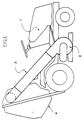
- the machines for picking up the grass after mowing are generally constituted by a vehicle (1), on which is mounted an assembly to ensure the collection and storage of l 'grass.
- a vehicle (1) on which is mounted an assembly to ensure the collection and storage of l 'grass.
- Such an assembly essentially consists of a head (2) movable near the surface of the ground, and which comprises a turbine making it possible to take the grass from the ground and to transfer it by means of a connection conduit (3 ) to a storage enclosure (4) disposed at the rear of the vehicle.
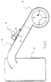
- the device according to the invention is in the form of a block (or case) adaptable to a wall of the material transfer circuit between the outlet of the turbine and the receptacle or storage enclosure and this, above a window or opening made on said circuit, said block comprising on the one hand a chamber open to the outside serving as a cage for a flexible shutter maintained normally pressed against the window or opening made in the circuit and this, so as to close it off, by forming a surface complementary to the internal surface of the transfer duct and without any protuberance inside said duct, said flap being mounted inside the chamber, so to be able, on the one hand, to flex inside said chamber during normal variations in the flow of air and of material with a minimum of air leaks outwards and, on the other hand, during a surprise permanent ession inside the transmission duct (produced by an accidental jam or a filling of the storage enclosure), to be pivoted automatically away from the window and, during this movement, to cause tripping an audible or visual alarm, integrated in a sealed chamber
- the flexible shutter shutter is based on a rot-proof material, resistant to impact, and is constituted for example by a blade or plate based on an elastomer, such as that sold under the brand "HYTREL" by the company DU PONT DE NEMOURS.
- a rot-proof material resistant to impact
- an elastomer such as that sold under the brand "HYTREL” by the company DU PONT DE NEMOURS.
- any other type of material having characteristics of flexibility and shock absorption could be used.
- Said flexible, flexible plate has a lower surface corresponding to the internal surface of the conduit, this surface however being advantageously flat and the device according to the invention being disposed in an area of the connecting conduit, the cross section of which is such that the surface internal is also flat.
- This flexible blade and the corresponding window made in the connection circuit have corresponding shapes, the blade being fixed to the housing along one of its ends and its other free edges tangent to the corresponding side walls of the open cage. of the housing, which are in the form of a curved surface corresponding to the surface described by the free edges of the flap when it bends.
- the flexible blade is of trapezoidal shape and is fixed to the housing along the large base of this trapezoid, the three other free edges coming to tangent with the side walls of the open cage of the housing.
- the alarm means associated with the device according to the invention are, according to a preferred embodiment, constituted by a system of magnetic sensors comprising a magnetic pad mounted at the end of the flexible blade and a magnetic contactor disposed at the inside the sealed chamber, and which triggers an alarm system (horn, warning light, etc.), the supply means of which are also arranged inside the sealed chamber of the housing.
- a system of magnetic sensors comprising a magnetic pad mounted at the end of the flexible blade and a magnetic contactor disposed at the inside the sealed chamber, and which triggers an alarm system (horn, warning light, etc.), the supply means of which are also arranged inside the sealed chamber of the housing.
- such a device can be actuated manually, for example when one wishes to test its correct operation.
- it is possible to be able to move the blade for example by providing on its upper surface a raised part allowing it to be grasped, so as to be able to bring the magnetic stud mounted at the end of the blade opposite the contactor disposed inside the sealed chamber, in order to control the proper functioning of the alarm system.
- the device according to the invention designated by the general reference (5) is therefore constituted by an assembly disposed at the outlet of the turbine (2) sampling material on the conduit (3) for bringing said material inside the enclosure (4) for storage associated with a vehicle.
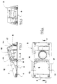
- Such an assembly (5) consists essentially of a block or case, in one piece, preferably produced by molding from a plastic material.
- the alarm means associated with the device consist of a system of magnetic sensors, the material chosen from any material permeable to magnetic flux.
- This block or case is mounted on the material transfer circuit (3) (not shown in Figures 3 to 5), above a window or opening (6) made on this circuit. According to the illustrated embodiment, this window is produced in a flat area of the transfer circuit, for example directly at the outlet of the turbine (2) where the discharge duct has a square section.
- This box includes a chamber open (7) to the outside, which serves as a cage for a flexible shutter shutter (8) normally held pressed against the window or opening (6) made in the transfer circuit, so that the '' seal.
- the lower surface of this flap (8) is smooth and forms a surface complementary to the internal surface of the transfer duct (3), and without any protuberance, protruding inside said duct.
- This shutter shutter (8) is based on a rot-resistant material resistant to shocks, for example based on an elastomer plate such as that sold under the brand "HYTREL" by the company DU PONT DE NEMOURS.
- this flexible and flexible plate has a trapezoidal shape (see FIG.
- these alarm means are constituted by a system of induction sensors, comprising a magnetic stud (14) fixed near the extreme edge (12) of the flexible blade (8) , and a magnetic contactor (15) disposed, for its part, inside the sealed chamber (30) on the other side of the wall (13) against which the end of the flexible blade (8) bears. ) when traveling.
- a magnetic contactor 15
- supply means battery 17
- the alarm system 18
- Such a set of simple design, particularly effective, has great reliability.
- such a device can be controlled manually by moving the blade, for example by providing on its upper surface a raised part allowing it to be grasped, so as to be able to bring the magnetic stud mounted at the end of the blade opposite of the contactor located inside the sealed chamber, in order to control the proper functioning of the alarm system.
Landscapes
- Life Sciences & Earth Sciences (AREA)
- Environmental Sciences (AREA)
- Engineering & Computer Science (AREA)
- Mechanical Engineering (AREA)
- Operating, Guiding And Securing Of Roll- Type Closing Members (AREA)
- Catching Or Destruction (AREA)
- Emergency Alarm Devices (AREA)
Claims (6)
- Einrichtung zur Erfassung der Füllung eines Behälters oder Speicherraums (4) in einer Anlage, in der das Zuführen von Material aus einem Speicherbereich zu diesem Behälter mit Hilfe einer Einheit realisiert ist, die eine Turbine (2) umfaßt, die es gestattet, das besagte Material aus dem Speicherbereich zu entnehmen und es durch Blasen (Ansaugen und/oder Antreiben) im Innern einer Leitung (3) in den Behälter (4) zu überführen, wobei die Leitung den Ausgang der besagten Turbine mit dem oberen Bereich des Auffangbehälters (4) verbunden ist, dadurch gekennzeichnet, daß die Einrichtung aus einem Kasten oder Gehäuse (5) besteht, der oder das auf einer Wand der Überführungsleitung (3) des Materials zwischen dem Ausgang der Turbine (2) und dem Behälter oder dem Speicherraum (4) oberhalb eines Fensters (6) oder einer Öffnung angeordnet ist, die auf dieser Leitung (3) vorgesehen ist, wobei der Kasten (5) einerseits eine nach außen offene Kammer (7) aufweist, die als Behältnis für eine biegsame Verschlußklappe (8) dient, die normalerweise gegen das Fenster oder die Öffnung (6) gehalten wird, wobei sie in einer verschließenden Weise eine komplementäre Oberfläche zu der inneren Oberfläche der Überführungsleitung (3) bildet, ohne daß ein Element nach innen in die Überführungsleitung hineinragt, wobei die besagte Klappe (8) im Innern der Kammer (7) angeordnet ist, um sich einerseits bei normalen Luftfluß-und Materialflußschwankungen in das Innere der besagten Kammer zu erstrekken, wobei ein Minimum an entweichender Luft nach außen auftritt, und um sich andererseits bei einem andauernden Überdruck im Innern der Überführungsleitung (3), der durch einen versehentlichen Stau oder eine Füllung der Speichereinfassung (4) hervorgerufen wird, automatisch zu verschwenken und um sich dabei von dem Fenster zu entfernen sowie bei dieser Bewegung einen akustischen oder visuellen Alarm auszulösen, der in einer abgeschlossenen Kammer (30) integriert ist, die in dem Kasten oder Gehäuse (5) angeordnet und mit diesem verbunden ist.
- Einrichtung nach Anspruch 1, dadurch gekennzeichnet, daß die biegsame Verschlußklappe (8) aus einem nicht-faulenden, stoßunempfindlichen Material, wie ein Blatt aus einem Elastomer, besteht.
- Einrichtung nach Anspruch 1 oder Anspruch 2, dadurch gekennzeichnet, daß die biegsame Klappe (oder Blatt) (8) und das zugehörige in der Verbindungsleitung (3) angeordnete Fenster (6) über sich entsprechende Formen verfügen, wobei das Blatt (8) an dem Kasten (5) entlang von einer seiner Seiten befestigt ist und die anderen freien Ränder mit den entsprechenden seitlichen Wänden des offenen Behältnisses (7) des Kastens (5) in berührender Verbindung stehen, die die Gestalt einer gekrümmten Oberfläche aufweisen, die der durch die freien Ränder der Klappe (8) während ihrer Verbiegung beschriebenen Oberfläche entsprechen.
- Einrichtung nach Anspruch 3, dadurch gekennzeichnet, daß das biegsame Blatt (8) und das zugehörige Fenster (6) eine trapezoidale Form aufweisen und daß das Blatt an dem Kasten (5) an der längeren Grundkante dieses Trapezes befestigt ist und die drei anderen freien Kanten (10, 11, 12) in berührender Verbindung mit den seitlichen Wänden des offenen Behältnisses (7) des Kastens (5) stehen, dessen der Knicklinie (9) des Blattes (8) gegenüberliegende Vorderwand (13) die Gestalt einer gekrümmten Oberfläche aufweist, die der Oberfläche entspricht, die von der freien Seite (12) der Klappe (8) während ihrer Verbiegung beschrieben wird.
- Einrichtung nach einem der Ansprüche 1 bis 4, dadurch gekennzeichnet, daß die Alarm gebenden Mittel, die der Einrichtung zugeordnet sind, aus einem System von magnetischen Erfassungsmitteln aufgebaut sind, die einen magnetischen Fühler (14), der am Ende des biegsamen Blattes angeordnet ist, und einen magnetischen Kontaktgeber (15) umfassen, der im Innern der dichten Kammer (30) angeordnet ist, und der es gestattet, ein Alarmsystem (18) auszulösen, dessen Stromversorgungsmittel ebenfalls im Innern der dichten Kammer des Kastens angeordnet sind.
- Einrichtung nach Anspruch 5, dadurch gekennzeichnet, daß das biegsame Blatt (8) an seiner oberen Oberfläche über Mittel (reliefartige Abschnitte) verfügt, der ihr Ergreifen gestatten, um den magnetischen Fühler (8), der am Ende des biegsamen Blattes angeordnet ist, in Gegenüberstellung mit dem Kontaktgeber (15) zu überführen, der im Inneren der dichten Kammer vorgesehen ist, um das einwandfreie Arbeiten des Alarmsystems zu kontrollieren.
Applications Claiming Priority (2)
| Application Number | Priority Date | Filing Date | Title |
|---|---|---|---|
| FR9002696A FR2658800B1 (fr) | 1990-02-27 | 1990-02-27 | Dispositif permettant de detecter le remplissage d'un receptacle lors d'une operation de transfert de matiere depuis une zone de stockage jusqu'audit receptacle. |
| FR9002696 | 1990-02-27 |
Publications (2)
| Publication Number | Publication Date |
|---|---|
| EP0470243A1 EP0470243A1 (de) | 1992-02-12 |
| EP0470243B1 true EP0470243B1 (de) | 1993-09-01 |
Family
ID=9394350
Family Applications (1)
| Application Number | Title | Priority Date | Filing Date |
|---|---|---|---|
| EP91906314A Expired - Lifetime EP0470243B1 (de) | 1990-02-27 | 1991-02-26 | Einrichtung zur erfassung der füllung eines behälters während des zuführens von material aus einer speicherzone zu diesem behälter |
Country Status (5)
| Country | Link |
|---|---|
| EP (1) | EP0470243B1 (de) |
| AU (1) | AU7480491A (de) |
| DE (1) | DE69100328T2 (de) |
| FR (1) | FR2658800B1 (de) |
| WO (1) | WO1991013008A1 (de) |
Families Citing this family (4)
| Publication number | Priority date | Publication date | Assignee | Title |
|---|---|---|---|---|
| DE4403893A1 (de) * | 1994-02-08 | 1995-08-10 | Claas Ohg | Vorrichtung zur automatischen Befüllung von Ladebehältern mit einem Gutstrom |
| IT233499Y1 (it) * | 1994-06-15 | 2000-01-28 | Castel Garden Equip | Dispositivo per il rilevamento della condizione di sacco pieno in una macchina rasaerba con sacco di raccolta dell'erba tagliata |
| FR2750005B1 (fr) * | 1996-06-20 | 1998-07-24 | Techni Ind | Detecteur de remplissage de bac |
| US6622465B2 (en) | 2001-07-10 | 2003-09-23 | Deere & Company | Apparatus and method for a material collection fill indicator |
Citations (1)
| Publication number | Priority date | Publication date | Assignee | Title |
|---|---|---|---|---|
| UST988005I4 (en) * | 1976-03-15 | 1979-11-06 | International Harvester Company | Automatic feed control system |
Family Cites Families (2)
| Publication number | Priority date | Publication date | Assignee | Title |
|---|---|---|---|---|
| US4172515A (en) * | 1976-01-30 | 1979-10-30 | Hauni-Werke Korber & Co. K.G. | Method and apparatus for supplying tobacco to tobacco cutting machines |
| SE453044B (sv) * | 1986-02-21 | 1988-01-11 | Rippelton Nv | Utrustning for hantering av skordegods |
-
1990
- 1990-02-27 FR FR9002696A patent/FR2658800B1/fr not_active Expired - Fee Related
-
1991
- 1991-02-26 DE DE1991600328 patent/DE69100328T2/de not_active Expired - Fee Related
- 1991-02-26 AU AU74804/91A patent/AU7480491A/en not_active Abandoned
- 1991-02-26 EP EP91906314A patent/EP0470243B1/de not_active Expired - Lifetime
- 1991-02-26 WO PCT/FR1991/000155 patent/WO1991013008A1/fr not_active Ceased
Patent Citations (1)
| Publication number | Priority date | Publication date | Assignee | Title |
|---|---|---|---|---|
| UST988005I4 (en) * | 1976-03-15 | 1979-11-06 | International Harvester Company | Automatic feed control system |
Also Published As
| Publication number | Publication date |
|---|---|
| DE69100328D1 (de) | 1993-10-07 |
| WO1991013008A1 (fr) | 1991-09-05 |
| FR2658800A1 (fr) | 1991-08-30 |
| DE69100328T2 (de) | 1993-12-09 |
| EP0470243A1 (de) | 1992-02-12 |
| AU7480491A (en) | 1991-09-18 |
| FR2658800B1 (fr) | 1992-04-30 |
Similar Documents
| Publication | Publication Date | Title |
|---|---|---|
| FR2578942A1 (fr) | Appareil de nettoyage pour piscine | |
| FR2861348A1 (fr) | Montage d'une camera de vision arriere dans un boitier de protection comportant une fenetre de vision | |
| FR2683701A1 (fr) | Detecteur de sac a herbe plein pour une tondeuse a gazon. | |
| EP0470243B1 (de) | Einrichtung zur erfassung der füllung eines behälters während des zuführens von material aus einer speicherzone zu diesem behälter | |
| EP1067857B1 (de) | Elektrischer apparat zur aufnahme von abfällen | |
| EP0951229A1 (de) | Verbindungsvorrichtung für einen staubsaugerbeutel | |
| FR2991949A1 (fr) | Balai d'essuyage a connecteur hydraulique | |
| EP0524118A1 (de) | Vorrichtung zum Aufsammeln und Einlagern von Gras | |
| FR3091912A1 (fr) | dispositif de freinage comportant une plaquette de freinage adaptée pour collecter des poussières de freinage ET plaquette de freinage correspondante | |
| FR2773190A1 (fr) | Assemblage de poignee de porte exterieure | |
| FR2932947A1 (fr) | Dispositif de detection de quantite d'herbe coupee pour conteneur de collecte d'herbe d'une tondeuse a gazon | |
| FR2639543A1 (fr) | Dispositif de recuperation de residus liquides, a usage unique | |
| EP3381754B1 (de) | Kappe und scheibenwischerarm für kraftfahrzeug | |
| FR2696897A1 (fr) | Tondeuse à gazon avec collecteur par aspiration. | |
| EP0634586B1 (de) | Endstück für einen Reibbelagverschleisssensor, insbesondere für Bremsbeläge | |
| EP1522829A2 (de) | Vorrichtung zur Bestimmung eines Flüssigkeitsniveaus | |
| EP4248821A1 (de) | Staubsauger mit einer benutzerschnittstelle mit verbesserter abdichtung | |
| EP3626137B1 (de) | Drehschüttelvorrichtung für getränkezubereitungsmaschine, die mit einer magnetischen kupplungsvorrichtung ausgestattet ist | |
| EP2349177B1 (de) | Hygienischer schnuller | |
| EP3981314B1 (de) | Überlaufschutz-abschaltsystem | |
| EP3674492B1 (de) | Tauchbarer sanitärer zerkleinerer | |
| FR3109632A1 (fr) | Dispositif de détection d’une pression amélioré | |
| EP0695137B1 (de) | Fernbedienungseinrichtung für eine zentrale staubabsauganlage | |
| FR2707833A3 (fr) | Collecteur pour tondeuse à gazon. | |
| FR2682603A1 (fr) | Dispositif pour commander manuellement l'aspiration dans une sonde tracheale. |
Legal Events
| Date | Code | Title | Description |
|---|---|---|---|
| PUAI | Public reference made under article 153(3) epc to a published international application that has entered the european phase |
Free format text: ORIGINAL CODE: 0009012 |
|
| AK | Designated contracting states |
Kind code of ref document: A1 Designated state(s): DE FR GB IT |
|
| 17P | Request for examination filed |
Effective date: 19920217 |
|
| RAP1 | Party data changed (applicant data changed or rights of an application transferred) |
Owner name: S.A. KUBOTA EUROPE Owner name: CREATIONS DELERY |
|
| 17Q | First examination report despatched |
Effective date: 19930217 |
|
| GRAA | (expected) grant |
Free format text: ORIGINAL CODE: 0009210 |
|
| AK | Designated contracting states |
Kind code of ref document: B1 Designated state(s): DE FR GB IT |
|
| GBT | Gb: translation of ep patent filed (gb section 77(6)(a)/1977) |
Effective date: 19930827 |
|
| REF | Corresponds to: |
Ref document number: 69100328 Country of ref document: DE Date of ref document: 19931007 |
|
| ITF | It: translation for a ep patent filed | ||
| PLBE | No opposition filed within time limit |
Free format text: ORIGINAL CODE: 0009261 |
|
| STAA | Information on the status of an ep patent application or granted ep patent |
Free format text: STATUS: NO OPPOSITION FILED WITHIN TIME LIMIT |
|
| 26N | No opposition filed | ||
| REG | Reference to a national code |
Ref country code: FR Ref legal event code: CL |
|
| REG | Reference to a national code |
Ref country code: FR Ref legal event code: TP |
|
| PGFP | Annual fee paid to national office [announced via postgrant information from national office to epo] |
Ref country code: FR Payment date: 20000302 Year of fee payment: 10 |
|
| PGFP | Annual fee paid to national office [announced via postgrant information from national office to epo] |
Ref country code: GB Payment date: 20010201 Year of fee payment: 11 Ref country code: DE Payment date: 20010201 Year of fee payment: 11 |
|
| REG | Reference to a national code |
Ref country code: GB Ref legal event code: 732E |
|
| PG25 | Lapsed in a contracting state [announced via postgrant information from national office to epo] |
Ref country code: FR Free format text: LAPSE BECAUSE OF NON-PAYMENT OF DUE FEES Effective date: 20011031 |
|
| REG | Reference to a national code |
Ref country code: FR Ref legal event code: ST |
|
| REG | Reference to a national code |
Ref country code: GB Ref legal event code: IF02 |
|
| PG25 | Lapsed in a contracting state [announced via postgrant information from national office to epo] |
Ref country code: GB Free format text: LAPSE BECAUSE OF NON-PAYMENT OF DUE FEES Effective date: 20020226 |
|
| PG25 | Lapsed in a contracting state [announced via postgrant information from national office to epo] |
Ref country code: DE Free format text: LAPSE BECAUSE OF NON-PAYMENT OF DUE FEES Effective date: 20020903 |
|
| GBPC | Gb: european patent ceased through non-payment of renewal fee |
Effective date: 20020226 |
|
| PG25 | Lapsed in a contracting state [announced via postgrant information from national office to epo] |
Ref country code: IT Free format text: LAPSE BECAUSE OF NON-PAYMENT OF DUE FEES Effective date: 20050226 |