EP0470151B1 - Injection moulded golf club and method for its manufacture - Google Patents
Injection moulded golf club and method for its manufacture Download PDFInfo
- Publication number
- EP0470151B1 EP0470151B1 EP90907201A EP90907201A EP0470151B1 EP 0470151 B1 EP0470151 B1 EP 0470151B1 EP 90907201 A EP90907201 A EP 90907201A EP 90907201 A EP90907201 A EP 90907201A EP 0470151 B1 EP0470151 B1 EP 0470151B1
- Authority
- EP
- European Patent Office
- Prior art keywords
- mould
- polymer
- club
- fluid
- thermoplastic
- Prior art date
- Legal status (The legal status is an assumption and is not a legal conclusion. Google has not performed a legal analysis and makes no representation as to the accuracy of the status listed.)
- Expired - Lifetime
Links
- 238000004519 manufacturing process Methods 0.000 title claims abstract description 5
- 238000000034 method Methods 0.000 title claims description 20
- 238000002347 injection Methods 0.000 title description 3
- 239000007924 injection Substances 0.000 title description 3
- 229920003235 aromatic polyamide Polymers 0.000 claims abstract description 5
- 238000001746 injection moulding Methods 0.000 claims abstract description 5
- 239000004760 aramid Substances 0.000 claims abstract description 4
- 229920000642 polymer Polymers 0.000 claims description 22
- 239000012530 fluid Substances 0.000 claims description 12
- 239000000463 material Substances 0.000 claims description 10
- 238000000465 moulding Methods 0.000 claims description 6
- 230000003014 reinforcing effect Effects 0.000 claims description 5
- 239000000945 filler Substances 0.000 claims description 4
- FPAFDBFIGPHWGO-UHFFFAOYSA-N dioxosilane;oxomagnesium;hydrate Chemical group O.[Mg]=O.[Mg]=O.[Mg]=O.O=[Si]=O.O=[Si]=O.O=[Si]=O.O=[Si]=O FPAFDBFIGPHWGO-UHFFFAOYSA-N 0.000 claims description 3
- OKTJSMMVPCPJKN-UHFFFAOYSA-N Carbon Chemical compound [C] OKTJSMMVPCPJKN-UHFFFAOYSA-N 0.000 claims description 2
- 229910052799 carbon Inorganic materials 0.000 claims description 2
- 239000011521 glass Substances 0.000 claims description 2
- IJGRMHOSHXDMSA-UHFFFAOYSA-N Atomic nitrogen Chemical compound N#N IJGRMHOSHXDMSA-UHFFFAOYSA-N 0.000 abstract description 16
- 229920001169 thermoplastic Polymers 0.000 abstract description 13
- 239000004416 thermosoftening plastic Substances 0.000 abstract description 13
- 229910052757 nitrogen Inorganic materials 0.000 abstract description 8
- 239000004677 Nylon Substances 0.000 abstract description 4
- 229920001778 nylon Polymers 0.000 abstract description 4
- PCHJSUWPFVWCPO-UHFFFAOYSA-N gold Chemical compound [Au] PCHJSUWPFVWCPO-UHFFFAOYSA-N 0.000 abstract 1
- 239000010931 gold Substances 0.000 abstract 1
- 229910052737 gold Inorganic materials 0.000 abstract 1
- 239000012815 thermoplastic material Substances 0.000 abstract 1
- DHKHKXVYLBGOIT-UHFFFAOYSA-N acetaldehyde Diethyl Acetal Natural products CCOC(C)OCC DHKHKXVYLBGOIT-UHFFFAOYSA-N 0.000 description 2
- 125000002777 acetyl group Chemical class [H]C([H])([H])C(*)=O 0.000 description 2
- 235000009508 confectionery Nutrition 0.000 description 2
- 235000000396 iron Nutrition 0.000 description 2
- 239000007787 solid Substances 0.000 description 2
- 229910001369 Brass Inorganic materials 0.000 description 1
- 229920000271 Kevlar® Polymers 0.000 description 1
- 238000005299 abrasion Methods 0.000 description 1
- 239000010951 brass Substances 0.000 description 1
- 238000010276 construction Methods 0.000 description 1
- 239000000835 fiber Substances 0.000 description 1
- 239000004761 kevlar Substances 0.000 description 1
- 239000002184 metal Substances 0.000 description 1
- 238000012986 modification Methods 0.000 description 1
- 230000004048 modification Effects 0.000 description 1
Images
Classifications
-
- B—PERFORMING OPERATIONS; TRANSPORTING
- B29—WORKING OF PLASTICS; WORKING OF SUBSTANCES IN A PLASTIC STATE IN GENERAL
- B29C—SHAPING OR JOINING OF PLASTICS; SHAPING OF MATERIAL IN A PLASTIC STATE, NOT OTHERWISE PROVIDED FOR; AFTER-TREATMENT OF THE SHAPED PRODUCTS, e.g. REPAIRING
- B29C45/00—Injection moulding, i.e. forcing the required volume of moulding material through a nozzle into a closed mould; Apparatus therefor
- B29C45/17—Component parts, details or accessories; Auxiliary operations
- B29C45/1703—Introducing an auxiliary fluid into the mould
- B29C45/1704—Introducing an auxiliary fluid into the mould the fluid being introduced into the interior of the injected material which is still in a molten state, e.g. for producing hollow articles
-
- B—PERFORMING OPERATIONS; TRANSPORTING
- B29—WORKING OF PLASTICS; WORKING OF SUBSTANCES IN A PLASTIC STATE IN GENERAL
- B29C—SHAPING OR JOINING OF PLASTICS; SHAPING OF MATERIAL IN A PLASTIC STATE, NOT OTHERWISE PROVIDED FOR; AFTER-TREATMENT OF THE SHAPED PRODUCTS, e.g. REPAIRING
- B29C45/00—Injection moulding, i.e. forcing the required volume of moulding material through a nozzle into a closed mould; Apparatus therefor
- B29C45/0005—Injection moulding, i.e. forcing the required volume of moulding material through a nozzle into a closed mould; Apparatus therefor using fibre reinforcements
-
- B—PERFORMING OPERATIONS; TRANSPORTING
- B29—WORKING OF PLASTICS; WORKING OF SUBSTANCES IN A PLASTIC STATE IN GENERAL
- B29C—SHAPING OR JOINING OF PLASTICS; SHAPING OF MATERIAL IN A PLASTIC STATE, NOT OTHERWISE PROVIDED FOR; AFTER-TREATMENT OF THE SHAPED PRODUCTS, e.g. REPAIRING
- B29C45/00—Injection moulding, i.e. forcing the required volume of moulding material through a nozzle into a closed mould; Apparatus therefor
- B29C45/0013—Injection moulding, i.e. forcing the required volume of moulding material through a nozzle into a closed mould; Apparatus therefor using fillers dispersed in the moulding material, e.g. metal particles
-
- B—PERFORMING OPERATIONS; TRANSPORTING
- B29—WORKING OF PLASTICS; WORKING OF SUBSTANCES IN A PLASTIC STATE IN GENERAL
- B29C—SHAPING OR JOINING OF PLASTICS; SHAPING OF MATERIAL IN A PLASTIC STATE, NOT OTHERWISE PROVIDED FOR; AFTER-TREATMENT OF THE SHAPED PRODUCTS, e.g. REPAIRING
- B29C45/00—Injection moulding, i.e. forcing the required volume of moulding material through a nozzle into a closed mould; Apparatus therefor
- B29C45/17—Component parts, details or accessories; Auxiliary operations
- B29C45/1703—Introducing an auxiliary fluid into the mould
- B29C45/1704—Introducing an auxiliary fluid into the mould the fluid being introduced into the interior of the injected material which is still in a molten state, e.g. for producing hollow articles
- B29C2045/1723—Introducing an auxiliary fluid into the mould the fluid being introduced into the interior of the injected material which is still in a molten state, e.g. for producing hollow articles using fibre reinforcements
-
- B—PERFORMING OPERATIONS; TRANSPORTING
- B29—WORKING OF PLASTICS; WORKING OF SUBSTANCES IN A PLASTIC STATE IN GENERAL
- B29L—INDEXING SCHEME ASSOCIATED WITH SUBCLASS B29C, RELATING TO PARTICULAR ARTICLES
- B29L2031/00—Other particular articles
- B29L2031/52—Sports equipment ; Games; Articles for amusement; Toys
- B29L2031/5227—Clubs
Definitions
- This invention concerns improvements in or relating to golf clubs and particularly but not exclusively to a method of manufacturing a golf club with an integral head and shaft.
- a golf club is known from FR-A-2 523 854, whereby the club is injection moulded around a core.
- a method of manufacturing a golf club by injection moulding comprising introducing a required volume of polymer into a correspondingly shaped mould, introducing a required volume of pressurised fluid such that the fluid urges the polymer to line the walls of the mould, and maintaining the fluid under pressure for a predetermined period of time to allow the hollow club thus formed to cool, the polymer being fed into the mould such that the wall thickness of the shaft of the club increases towards the head of the club.
- the fluid is preferably introduced into the mould simultaneously with the polymer after a first portion of the polymer has already been introduced thereinto.
- the fluid and polymer may be introduced into the mould at substantially the same location.
- the fluid may be introduced into the mould downstream of introduction of the polymer.
- the polymer includes reinforcing fibres which may be of the long grade type.
- the polymer may be nylon or acetal, and the fibres may be glass, aramid ("Kevlar”), or carbon.
- a sole plate and/or other items may be positioned in the mould prior to moulding, to be incorporated into the club head.
- the mould may be shaped such that openings are formed extending in to the club head which can subsequently be filled with a relatively dense material to weight the club.
- a filler may be provided in the polymer such as talcum powder.
- the club After moulding the club may be filled with a curable material which may be resinous.
- a golf club manufactured by a method according to any of the preceding eight paragraphs.
- a golf club may be formed by feeding a predetermined weight of aramid reinforced nylon thermoplastics material from the screw of an injection moulding system into the handle end of a suitably shaped mould. After an initial portion of the thermoplastic has passed into the mould a stream of a predetermined volume of nitrogen under pressure is introduced into the centre of the thermoplastic feed to urge the thermoplastic against the inner walls of the mould to form a hollow club. When the feed and stream into the mould have been completed, the mould is maintained under pressure for a period of time, e.g. twenty seconds, to allow the thermoplastic to set. The nitrogen is then released and the mould opened to release the club.
- the aramid fibres are of the long grade type and will be typically 10 mm long as opposed to 0.2 - 0.4 mm for short grade type fibres. This length of fibres gives a relatively stiff shaft.
- a sole plate can be positioned in the mould prior to moulding which will adhere to the thermoplastic to provide weight in the required position on the base of the club's head and also protection against abrasion from rubbing on the ground.
- the sole plate can be made from any suitable material such as brass.
- the sole plate can be aligned in the mould such that the club being formed adopts the correct lie for a particular player. For example a taller player holds any one club at a greater angle to the vertical than a shorter player holds the same club, but preferably the base of the club should still be parallel to the ground for both players.
- the polymer is fed into the mould such that the shaft thickness increases towards the club head. This variation in shaft thickness provides an advantageous whip action when playing a shot.
- a hollow head will tend to provide a larger than normal "sweet spot", and if a shot is hit slightly off centre on the side edge of the "sweet spot” the head will tend to correct the skew of the shot due to the flexing of the face of the club.
- the hollow construction of the shaft and head tends to relieve the stress which is likely to be encountered in solid components when injection moulded.
- the club may be filled with a curable material which may be resinous.
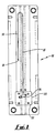
- Figs. 1 and 2 show a mould 10 suitable for use with such a method.
- the mould 10 is generally elongate and comprises two main detachable parts 12,14.
- the mould 10 defines an elongate channel 16 extending from an inlet 18 substantially midway along the mould 10 to a point adjacent one end, through a 180° turn to extend to connect with a cavity 20 adjacent the other end.
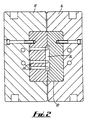
- the cavity 20 locates a two piece head mould 22 defining a chamber 24 connecting with the channel 16.
- the golf club being formed with a shaft formed in the part of the channel 16 extending into the cavity 20 and the head formed in the chamber 24.
- Fingers 26 are provided in the mould 22 extending into the chamber 24 to produce openings into the golf club head which may be filled with a relatively dense material to weight the club. Different moulds 22 can obviously be placed in the chamber 24 to form different clubs.
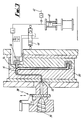
- FIG. 3 shows a system using a mould 30 in which the thermoplastic feed is introduced at a first inlet 32 and the stream of nitrogen is introduced at a second inlet 34 adjacent the turn in the channel 16.
- the thermoplastic feed comes from the screw 36 of an injection moulding system through a valve 38.
- the stream of nitrogen issues from a cylinder 40 connected to a supply of nitrogen 42 and is urged into the mould by a hydraulic cylinder 44 controlled by a valve 46.
- the same mould could be used to make a number of different clubs using different head moulds, and suitable inserts could be provided for the mould for the different features on different clubs.
- the head could be filled with material such as molten metal to add weight thereto and vary the striking characteristic of the golf club.
- the method can be used for both woods and irons. Irons could have a solid head or a head with one or more hollow compartments.
Landscapes
- Engineering & Computer Science (AREA)
- Manufacturing & Machinery (AREA)
- Mechanical Engineering (AREA)
- Chemical & Material Sciences (AREA)
- Dispersion Chemistry (AREA)
- Golf Clubs (AREA)
- Injection Moulding Of Plastics Or The Like (AREA)
- Footwear And Its Accessory, Manufacturing Method And Apparatuses (AREA)
Abstract
Description
- This invention concerns improvements in or relating to golf clubs and particularly but not exclusively to a method of manufacturing a golf club with an integral head and shaft. Such a golf club is known from FR-A-2 523 854, whereby the club is injection moulded around a core.
- According to the present invention there is provided a method of manufacturing a golf club by injection moulding, the method comprising introducing a required volume of polymer into a correspondingly shaped mould, introducing a required volume of pressurised fluid such that the fluid urges the polymer to line the walls of the mould, and maintaining the fluid under pressure for a predetermined period of time to allow the hollow club thus formed to cool, the polymer being fed into the mould such that the wall thickness of the shaft of the club increases towards the head of the club.
- The fluid is preferably introduced into the mould simultaneously with the polymer after a first portion of the polymer has already been introduced thereinto.
- The fluid and polymer may be introduced into the mould at substantially the same location. Alternatively the fluid may be introduced into the mould downstream of introduction of the polymer.
- Preferably the polymer includes reinforcing fibres which may be of the long grade type. The polymer may be nylon or acetal, and the fibres may be glass, aramid ("Kevlar"), or carbon.
- A sole plate and/or other items may be positioned in the mould prior to moulding, to be incorporated into the club head.
- The mould may be shaped such that openings are formed extending in to the club head which can subsequently be filled with a relatively dense material to weight the club.
- A filler may be provided in the polymer such as talcum powder.
- After moulding the club may be filled with a curable material which may be resinous.
- Also according to the present invention there is provided a golf club manufactured by a method according to any of the preceding eight paragraphs.
- Examples of how the invention may be carried out will now be described by way of example only with reference to the accompanying drawings in which:-
- Fig. 1 is a diagrammatic plan view of a mould usable with the invention;
- Fig. 2 is a cross-sectional side view of the mould of fig. 1; and
- Fig. 3 is a diagrammatic plan view of apparatus usable with the invention.
- A golf club may be formed by feeding a predetermined weight of aramid reinforced nylon thermoplastics material from the screw of an injection moulding system into the handle end of a suitably shaped mould. After an initial portion of the thermoplastic has passed into the mould a stream of a predetermined volume of nitrogen under pressure is introduced into the centre of the thermoplastic feed to urge the thermoplastic against the inner walls of the mould to form a hollow club. When the feed and stream into the mould have been completed, the mould is maintained under pressure for a period of time, e.g. twenty seconds, to allow the thermoplastic to set. The nitrogen is then released and the mould opened to release the club.
- The aramid fibres are of the long grade type and will be typically 10 mm long as opposed to 0.2 - 0.4 mm for short grade type fibres. This length of fibres gives a relatively stiff shaft.
- If required a sole plate can be positioned in the mould prior to moulding which will adhere to the thermoplastic to provide weight in the required position on the base of the club's head and also protection against abrasion from rubbing on the ground. The sole plate can be made from any suitable material such as brass. The sole plate can be aligned in the mould such that the club being formed adopts the correct lie for a particular player. For example a taller player holds any one club at a greater angle to the vertical than a shorter player holds the same club, but preferably the base of the club should still be parallel to the ground for both players.
- The polymer is fed into the mould such that the shaft thickness increases towards the club head. This variation in shaft thickness provides an advantageous whip action when playing a shot.
- The provision of a hollow head will tend to provide a larger than normal "sweet spot", and if a shot is hit slightly off centre on the side edge of the "sweet spot" the head will tend to correct the skew of the shot due to the flexing of the face of the club. The hollow construction of the shaft and head tends to relieve the stress which is likely to be encountered in solid components when injection moulded.
- If required, after moulding the club may be filled with a curable material which may be resinous.
- Whilst the fibres in the shaft will lie predominantly in a generally longitudinal alignment, some will cross over thus reducing any relative rotation of the shaft. Conventionaly fibre reinforced shafts are extruded or laid, and nearly all the fibres tend to a substantially longitudinal alignment. The provision of an integral shaft and head, with the fibres in the head aligned predominently substantially perpendicular to the fibres in the shaft will reduce rotation of the head about the shaft which can be experienced when the shaft and head are separate components.
- Figs. 1 and 2 show a
mould 10 suitable for use with such a method. Themould 10 is generally elongate and comprises two maindetachable parts mould 10 defines anelongate channel 16 extending from aninlet 18 substantially midway along themould 10 to a point adjacent one end, through a 180° turn to extend to connect with acavity 20 adjacent the other end. Thecavity 20 locates a twopiece head mould 22 defining achamber 24 connecting with thechannel 16. The golf club being formed with a shaft formed in the part of thechannel 16 extending into thecavity 20 and the head formed in thechamber 24.Fingers 26 are provided in themould 22 extending into thechamber 24 to produce openings into the golf club head which may be filled with a relatively dense material to weight the club.Different moulds 22 can obviously be placed in thechamber 24 to form different clubs. - With the mould 10 a stream of nitrogen and the thermoplastic feed are introduced at the same location, the
inlet 18. Fig. 3 shows a system using amould 30 in which the thermoplastic feed is introduced at afirst inlet 32 and the stream of nitrogen is introduced at asecond inlet 34 adjacent the turn in thechannel 16. The thermoplastic feed comes from thescrew 36 of an injection moulding system through avalve 38. The stream of nitrogen issues from acylinder 40 connected to a supply ofnitrogen 42 and is urged into the mould by ahydraulic cylinder 44 controlled by avalve 46. - There is thus described a method of producing a golf club, and a golf club produced by that method, which have a number of advantageous features. It is to be appreciated that various other modifications may be made without departing from the scope of the invention. For example clubs of different weights can easily be produced by using polymers of different densities. Different length reinforcing fibres can be used to provide shafts of different stiffness. Many other materials than those outlined above can be used for baking the clubs. Instead of nylon, acetal may be used. A filler such as talcum powder may be included in the polymer.
- The same mould could be used to make a number of different clubs using different head moulds, and suitable inserts could be provided for the mould for the different features on different clubs. If required the head could be filled with material such as molten metal to add weight thereto and vary the striking characteristic of the golf club. The method can be used for both woods and irons. Irons could have a solid head or a head with one or more hollow compartments.
Claims (13)
- A method of manufacturing a golf club by injection moulding, the method comprising introducing a required volume of polymer into a correspondingly shaped mould characterised by, introducing a required volume of pressurised fluid such that the fluid urges the polymer to line the walls of the mould, and maintaining the fluid under pressure for a predetermined period of time to allow the hollow club thus formed to cool, the polymer being fed into the mould such that the wall thickness of the shaft of the club increases towards the head of the club.
- A method according to claim 1, characterised in that the fluid is introduced into the mould simultaneously with the polymer after a first portion of the polymer has already been introduced thereinto.
- A method according to claims 1 or 2, characterised in that the fluid and polymer are introduced into the mould at substantially the same location.
- A method according to claims 1 or 2, characterised in that the fluid is introduced into the mould downstream of introduction of the polymer.
- A method according to any of the preceding claims, characterised in that the polymer includes reinforcing fibres.
- A method according to claim 5, characterised in that the reinforcing fibres are of the long grade type.
- A method according to claims 5 or 6, characterised in that the reinforcing fibres are any of glass, aramid, or carbon.
- A method according to any of the preceding claims, characterised in that a sole plate and/or other items are positioned in the mould prior to moulding, to be incorporated into the club head.
- A method according to any of the preceding claims, characterised in that the mould is shaped such that openings are formed extending into the club head.
- A method according to any of the preceding claims, characterised in that a filler is provided in the polymer.
- A method according to claim 10, characterised in that the filler is talcum powder.
- A method according to any of the preceding claims, characterised in that after moulding the club is filled with a curable material.
- A method according to claim 12, characterised in that the curable material is resinous.
Applications Claiming Priority (3)
| Application Number | Priority Date | Filing Date | Title |
|---|---|---|---|
| GB8909376 | 1989-04-25 | ||
| GB898909376A GB8909376D0 (en) | 1989-04-25 | 1989-04-25 | Improved golf club |
| PCT/GB1990/000631 WO1990012679A1 (en) | 1989-04-25 | 1990-04-24 | Injection moulded golf club and method for its manufacture |
Publications (2)
| Publication Number | Publication Date |
|---|---|
| EP0470151A1 EP0470151A1 (en) | 1992-02-12 |
| EP0470151B1 true EP0470151B1 (en) | 1994-09-07 |
Family
ID=10655659
Family Applications (1)
| Application Number | Title | Priority Date | Filing Date |
|---|---|---|---|
| EP90907201A Expired - Lifetime EP0470151B1 (en) | 1989-04-25 | 1990-04-24 | Injection moulded golf club and method for its manufacture |
Country Status (8)
| Country | Link |
|---|---|
| US (1) | US5277866A (en) |
| EP (1) | EP0470151B1 (en) |
| JP (1) | JPH05504692A (en) |
| AT (1) | ATE111014T1 (en) |
| AU (1) | AU5530690A (en) |
| DE (1) | DE69012322T2 (en) |
| GB (1) | GB8909376D0 (en) |
| WO (1) | WO1990012679A1 (en) |
Families Citing this family (17)
| Publication number | Priority date | Publication date | Assignee | Title |
|---|---|---|---|---|
| CA2086332C (en) * | 1990-07-16 | 1996-09-10 | James W. Hendry | Method and system for the injection molding of plastic articles utilizing a fluid compression unit |
| JPH082547B2 (en) * | 1991-08-13 | 1996-01-17 | 豊田合成株式会社 | Hollow molding method |
| US5468238A (en) * | 1993-06-11 | 1995-11-21 | Ethicon, Inc. | Endoscopic laser instrument |
| CA2134424A1 (en) * | 1994-10-26 | 1996-04-27 | Raymond T. Woodhams | Injection molding process for the production of oriented thermoplastic and particulate matter composite articles |
| US5798066A (en) * | 1995-07-12 | 1998-08-25 | Certech Incorporated | Method of forming hollow ceramic articles |
| GB9610373D0 (en) * | 1996-05-17 | 1996-07-24 | Tamworth Plastics Ltd | Method and apparatus for moulding elongate members and in particular golf club shafts |
| US5985197A (en) * | 1997-04-23 | 1999-11-16 | Radius Engineering, Inc. | Method of manufacturing a composite golf club head |
| US6340509B1 (en) * | 1997-04-23 | 2002-01-22 | Radius Engineering, Inc. | Composite bicycle frame and method of construction thereof |
| TW438658B (en) * | 1997-05-07 | 2001-06-07 | Idemitsu Petrochemical Co | Method of obtaining a gas-introduced fiber-reinforced resin injection molding and molding obtained by the same |
| US5788917A (en) * | 1997-05-27 | 1998-08-04 | General Motors Corporation | Method of making a plastic article |
| US7037211B1 (en) | 1999-08-10 | 2006-05-02 | Chapel Golf, Inc. | Golf club |
| US6692376B2 (en) | 1999-08-10 | 2004-02-17 | Chapel Golf, Inc. | Golf club |
| AU2001250893A1 (en) * | 2000-03-24 | 2001-10-15 | Lucini Italia Company | Improved golf club |
| CA2308877A1 (en) * | 2000-05-19 | 2001-11-19 | V-Flyte Golf Corporation | Golf club head |
| US6860820B2 (en) * | 2002-08-14 | 2005-03-01 | Chapel Golf, Inc. | Golf club and methods of manufacture |
| JP4287769B2 (en) * | 2004-03-17 | 2009-07-01 | Sriスポーツ株式会社 | Golf club head and manufacturing method thereof |
| TWM435288U (en) * | 2012-04-18 | 2012-08-11 | Wei-Jing Xu | Integrally made golf club |
Family Cites Families (31)
| Publication number | Priority date | Publication date | Assignee | Title |
|---|---|---|---|---|
| US1038429A (en) * | 1911-08-09 | 1912-09-10 | Herbert T Penny | Game-stick. |
| US3387844A (en) * | 1964-11-18 | 1968-06-11 | Winsor Shippee | Golf club with percussion chamber plenum |
| GB1201648A (en) * | 1967-12-20 | 1970-08-12 | Carlton Sports Company Ltd For | Improvements in or relating to golf clubs |
| JPS598367B2 (en) * | 1979-06-11 | 1984-02-24 | 鐘淵化学工業株式会社 | Expandable thermoplastic polymer particle composition |
| DE3265764D1 (en) * | 1981-05-15 | 1985-10-03 | Ici Plc | Process for moulding reinforced curable compositions |
| FR2523854A1 (en) * | 1982-03-25 | 1983-09-30 | Vennin Thierry | Golf club shafts with integral moulded plastic head - opt. including fibrous or dense fillers or inserts |
| US4451042A (en) * | 1982-04-07 | 1984-05-29 | Mizuno Corporation | Golf club head of carbon fiber reinforced plastic |
| US4581190A (en) * | 1982-04-23 | 1986-04-08 | Nippon Gakki Seizo Kabushiki Kaisha | Process for producing a wood-type golf club head |
| JPS5922576A (en) * | 1982-07-29 | 1984-02-04 | ヤマハ株式会社 | Production of wood club head for golf |
| JPS60190984A (en) * | 1984-03-13 | 1985-09-28 | ヤマハ株式会社 | Wood club for golf |
| GB2161109B (en) * | 1984-07-07 | 1988-12-21 | Rolls Royce | Integral bladed member |
| EP0168041B1 (en) * | 1984-07-10 | 1990-06-20 | Sumitomo Rubber Industries Limited | A ball striking instrument |
| US4650626A (en) * | 1984-07-13 | 1987-03-17 | Nippon Gakki Seizo Kabushiki Kaisha | Method of producing a golf club head |
| GB2172238B (en) * | 1985-03-12 | 1989-12-28 | Diversified Prod | Racquets |
| JPH0344215Y2 (en) * | 1985-04-01 | 1991-09-17 | ||
| EP0258233B1 (en) * | 1985-04-19 | 1989-12-20 | Paul Henri Viellard | Golf clubs and method for their fabrication |
| US4863771A (en) * | 1985-08-22 | 1989-09-05 | The Budd Company | Hollow fiber reinforced structure and method of making same |
| US4935191A (en) * | 1986-10-16 | 1990-06-19 | Thomas W. Johnson | Process of insection molding with pressurized gas assist |
| EP0255392B1 (en) * | 1986-07-30 | 1991-05-22 | Du Pont (Australia) Ltd.. | Reinforcing method and means |
| US4883623A (en) * | 1986-09-08 | 1989-11-28 | Yamaha Corporation | Method for producing a golf club head |
| JP2590325B2 (en) * | 1986-09-12 | 1997-03-12 | ブリヂストンスポーツ株式会社 | Golf club set |
| GB8706204D0 (en) * | 1987-03-16 | 1987-04-23 | Peerless Cinpres Ltd | Injection moulding apparatus |
| JPH0788025B2 (en) * | 1987-04-28 | 1995-09-27 | 三菱瓦斯化学株式会社 | Manufacturing method of synthetic resin molded product having uneven wall reinforcement structure |
| US4896885A (en) * | 1987-06-05 | 1990-01-30 | Bridgestone Corporation | Golf club |
| US4943407A (en) * | 1987-09-21 | 1990-07-24 | Michael Ladney | Method of and apparatus for injection molding with pressurized fluid assist |
| JP2537668B2 (en) * | 1988-09-19 | 1996-09-25 | 豊田合成株式会社 | Method for manufacturing resin molded products |
| JP2628358B2 (en) * | 1988-11-04 | 1997-07-09 | 横浜ゴム株式会社 | Golf club head |
| AT399470B (en) * | 1988-12-15 | 1995-05-26 | Head Sport Ag | METHOD FOR PRODUCING A BALL RACKET FRAME |
| US4936582A (en) * | 1989-02-24 | 1990-06-26 | Kenneth Bernstein | Golf club |
| US5093050A (en) * | 1989-11-17 | 1992-03-03 | Laboratorium Fur Experimentelle Chirurgie | Method for producing oriented, discontinuous fiber reinforced composite materials |
| US5071123A (en) * | 1990-09-21 | 1991-12-10 | Donald Spector | Toy implements for storing and striking play balls |
-
1989
- 1989-04-25 GB GB898909376A patent/GB8909376D0/en active Pending
-
1990
- 1990-04-24 US US07/773,914 patent/US5277866A/en not_active Expired - Fee Related
- 1990-04-24 DE DE69012322T patent/DE69012322T2/en not_active Expired - Fee Related
- 1990-04-24 WO PCT/GB1990/000631 patent/WO1990012679A1/en not_active Ceased
- 1990-04-24 EP EP90907201A patent/EP0470151B1/en not_active Expired - Lifetime
- 1990-04-24 JP JP2506658A patent/JPH05504692A/en active Pending
- 1990-04-24 AT AT90907201T patent/ATE111014T1/en not_active IP Right Cessation
- 1990-04-24 AU AU55306/90A patent/AU5530690A/en not_active Abandoned
Non-Patent Citations (1)
| Title |
|---|
| Composite Polymers, volume 1, no. 4, 1988, (Shawbury, Shrewsbury, Shropshire, GB), C.R. Gore: "Long fibre reinforced thermoplastic injection moulding compounds", pages 280-299; see page 281, line 26 - page 282, line 4; page 290, line 14 - page 293, line 3; page 294, lines 1-8; figure 26 * |
Also Published As
| Publication number | Publication date |
|---|---|
| AU5530690A (en) | 1990-11-16 |
| JPH05504692A (en) | 1993-07-22 |
| GB8909376D0 (en) | 1989-06-14 |
| EP0470151A1 (en) | 1992-02-12 |
| ATE111014T1 (en) | 1994-09-15 |
| DE69012322T2 (en) | 1995-04-06 |
| US5277866A (en) | 1994-01-11 |
| DE69012322D1 (en) | 1994-10-13 |
| WO1990012679A1 (en) | 1990-11-01 |
Similar Documents
| Publication | Publication Date | Title |
|---|---|---|
| EP0470151B1 (en) | Injection moulded golf club and method for its manufacture | |
| US10967231B2 (en) | Golf club heads and methods to manufacture golf club heads | |
| US4013288A (en) | Hockey stick | |
| US5333871A (en) | Golf club head | |
| US3507495A (en) | Lacrosse stick | |
| US5445382A (en) | Golf club head of entangled fiber reinforced plastic | |
| EP3097960B1 (en) | Hockey stick blade with logo system and co-moulding process | |
| GB2264439A (en) | Improved golf club head and methods for its manufacture | |
| JPH11197274A (en) | Densified packing film for use in composite material golf club head | |
| CA2088468C (en) | Composite hockey stick shaft and process for making same | |
| JP7755010B2 (en) | Golf club head | |
| KR102418775B1 (en) | Golf club head and golf club head manufacturing method | |
| US6802785B2 (en) | Golf balls including a layer with reinforced fibers and methods for forming such golf balls | |
| KR20230136211A (en) | golf club head with insert | |
| JPH0824377A (en) | Golf club head manufacturing method | |
| US20110077102A1 (en) | Golf club body fabricated with long carbon fiber material | |
| US11684831B2 (en) | Golf club heads and methods to manufacture golf club heads | |
| JP2534495B2 (en) | Iron golf club head and method of manufacturing the same | |
| JPH0793957B2 (en) | Golf club head manufacturing method | |
| US12303750B2 (en) | Golf club heads and methods to manufacture golf club heads | |
| JPS61249485A (en) | Golf club head | |
| BE1010467A6 (en) | Golf ball with a plastic skin and a hollow core | |
| JPS5949785A (en) | Head for golf club and production thereof | |
| WO2023178214A1 (en) | Injection molded ski | |
| JPS596073A (en) | Production of wood club head or golf |
Legal Events
| Date | Code | Title | Description |
|---|---|---|---|
| PUAI | Public reference made under article 153(3) epc to a published international application that has entered the european phase |
Free format text: ORIGINAL CODE: 0009012 |
|
| 17P | Request for examination filed |
Effective date: 19911022 |
|
| AK | Designated contracting states |
Kind code of ref document: A1 Designated state(s): AT BE CH DE DK ES FR GB IT LI LU NL SE |
|
| 17Q | First examination report despatched |
Effective date: 19931102 |
|
| GRAA | (expected) grant |
Free format text: ORIGINAL CODE: 0009210 |
|
| AK | Designated contracting states |
Kind code of ref document: B1 Designated state(s): AT BE CH DE DK ES FR GB IT LI LU NL SE |
|
| PG25 | Lapsed in a contracting state [announced via postgrant information from national office to epo] |
Ref country code: BE Effective date: 19940907 Ref country code: AT Effective date: 19940907 Ref country code: DK Effective date: 19940907 Ref country code: FR Effective date: 19940907 Ref country code: NL Effective date: 19940907 Ref country code: ES Free format text: THE PATENT HAS BEEN ANNULLED BY A DECISION OF A NATIONAL AUTHORITY Effective date: 19940907 Ref country code: IT Free format text: LAPSE BECAUSE OF FAILURE TO SUBMIT A TRANSLATION OF THE DESCRIPTION OR TO PAY THE FEE WITHIN THE PRE;WARNING: LAPSES OF ITALIAN PATENTS WITH EFFECTIVE DATE BEFORE 2007 MAY HAVE OCCURRED AT ANY TIME BEFORE 2007. THE CORRECT EFFECTIVE DATE MAY BE DIFFERENT FROM THE ONE RECORDED.SCRIBED TIME-LIMIT Effective date: 19940907 |
|
| REF | Corresponds to: |
Ref document number: 111014 Country of ref document: AT Date of ref document: 19940915 Kind code of ref document: T |
|
| REF | Corresponds to: |
Ref document number: 69012322 Country of ref document: DE Date of ref document: 19941013 |
|
| EAL | Se: european patent in force in sweden |
Ref document number: 90907201.9 |
|
| EN | Fr: translation not filed | ||
| NLV1 | Nl: lapsed or annulled due to failure to fulfill the requirements of art. 29p and 29m of the patents act | ||
| PG25 | Lapsed in a contracting state [announced via postgrant information from national office to epo] |
Ref country code: LU Free format text: LAPSE BECAUSE OF NON-PAYMENT OF DUE FEES Effective date: 19950430 |
|
| PLBE | No opposition filed within time limit |
Free format text: ORIGINAL CODE: 0009261 |
|
| STAA | Information on the status of an ep patent application or granted ep patent |
Free format text: STATUS: NO OPPOSITION FILED WITHIN TIME LIMIT |
|
| 26N | No opposition filed | ||
| PGFP | Annual fee paid to national office [announced via postgrant information from national office to epo] |
Ref country code: CH Payment date: 19960313 Year of fee payment: 7 |
|
| PG25 | Lapsed in a contracting state [announced via postgrant information from national office to epo] |
Ref country code: CH Free format text: LAPSE BECAUSE OF NON-PAYMENT OF DUE FEES Effective date: 19970430 Ref country code: LI Free format text: LAPSE BECAUSE OF NON-PAYMENT OF DUE FEES Effective date: 19970430 |
|
| REG | Reference to a national code |
Ref country code: GB Ref legal event code: 732E |
|
| REG | Reference to a national code |
Ref country code: CH Ref legal event code: PL |
|
| REG | Reference to a national code |
Ref country code: GB Ref legal event code: 732E |
|
| REG | Reference to a national code |
Ref country code: GB Ref legal event code: 732E Free format text: ADDENDUM: FURTHER TO THE REPORT OF A REGISTRATION ADVERTISED IN THE JOURNAL PUBLISHED 28 JULY 1999. A CORRECTION HAS BEEN MADE IN RESPECT OF EP 0470151 WHICH WAS REPORTED AS SUBJECT TO REGISTRATION OF A TRANSACTION/INSTRUMENT/EVENT AFFECTING THE RIGHTS OF THE PROPRIETOR. |
|
| REG | Reference to a national code |
Ref country code: GB Ref legal event code: 732E |
|
| REG | Reference to a national code |
Ref country code: GB Ref legal event code: IF02 |
|
| PGFP | Annual fee paid to national office [announced via postgrant information from national office to epo] |
Ref country code: GB Payment date: 20050419 Year of fee payment: 16 |
|
| PGFP | Annual fee paid to national office [announced via postgrant information from national office to epo] |
Ref country code: DE Payment date: 20050427 Year of fee payment: 16 |
|
| PGFP | Annual fee paid to national office [announced via postgrant information from national office to epo] |
Ref country code: SE Payment date: 20050429 Year of fee payment: 16 |
|
| PG25 | Lapsed in a contracting state [announced via postgrant information from national office to epo] |
Ref country code: GB Free format text: LAPSE BECAUSE OF NON-PAYMENT OF DUE FEES Effective date: 20060424 |
|
| PG25 | Lapsed in a contracting state [announced via postgrant information from national office to epo] |
Ref country code: SE Free format text: LAPSE BECAUSE OF NON-PAYMENT OF DUE FEES Effective date: 20060425 |
|
| PG25 | Lapsed in a contracting state [announced via postgrant information from national office to epo] |
Ref country code: DE Free format text: LAPSE BECAUSE OF NON-PAYMENT OF DUE FEES Effective date: 20061101 |
|
| EUG | Se: european patent has lapsed | ||
| GBPC | Gb: european patent ceased through non-payment of renewal fee |
Effective date: 20060424 |