EP3097960B1 - Hockey stick blade with logo system and co-moulding process - Google Patents
Hockey stick blade with logo system and co-moulding process Download PDFInfo
- Publication number
- EP3097960B1 EP3097960B1 EP16162546.2A EP16162546A EP3097960B1 EP 3097960 B1 EP3097960 B1 EP 3097960B1 EP 16162546 A EP16162546 A EP 16162546A EP 3097960 B1 EP3097960 B1 EP 3097960B1
- Authority
- EP
- European Patent Office
- Prior art keywords
- blade
- hockey stick
- weight
- logo
- weighted
- Prior art date
- Legal status (The legal status is an assumption and is not a legal conclusion. Google has not performed a legal analysis and makes no representation as to the accuracy of the status listed.)
- Active
Links
- 238000000034 method Methods 0.000 title claims description 58
- 230000008569 process Effects 0.000 title claims description 53
- 238000000465 moulding Methods 0.000 title description 8
- 239000002131 composite material Substances 0.000 claims description 98
- 239000000463 material Substances 0.000 claims description 76
- 239000008393 encapsulating agent Substances 0.000 claims description 44
- 239000004814 polyurethane Substances 0.000 claims description 26
- 229920002635 polyurethane Polymers 0.000 claims description 25
- 238000013037 co-molding Methods 0.000 claims description 21
- 229920003225 polyurethane elastomer Polymers 0.000 claims description 7
- 239000000835 fiber Substances 0.000 description 38
- 229920005989 resin Polymers 0.000 description 36
- 239000011347 resin Substances 0.000 description 36
- 229920000642 polymer Polymers 0.000 description 27
- 239000011162 core material Substances 0.000 description 25
- 238000009826 distribution Methods 0.000 description 20
- 229910052751 metal Inorganic materials 0.000 description 14
- 239000002184 metal Substances 0.000 description 14
- 238000005516 engineering process Methods 0.000 description 11
- 238000010276 construction Methods 0.000 description 10
- 238000013461 design Methods 0.000 description 10
- 239000006260 foam Substances 0.000 description 10
- 238000007373 indentation Methods 0.000 description 9
- -1 KevlarTM) Chemical compound 0.000 description 8
- 238000003491 array Methods 0.000 description 8
- 230000000694 effects Effects 0.000 description 8
- 239000011159 matrix material Substances 0.000 description 8
- 229920003023 plastic Polymers 0.000 description 8
- 239000004033 plastic Substances 0.000 description 8
- 239000007787 solid Substances 0.000 description 8
- 238000005266 casting Methods 0.000 description 7
- 238000012546 transfer Methods 0.000 description 6
- HCHKCACWOHOZIP-UHFFFAOYSA-N Zinc Chemical compound [Zn] HCHKCACWOHOZIP-UHFFFAOYSA-N 0.000 description 5
- 230000001070 adhesive effect Effects 0.000 description 5
- 230000001965 increasing effect Effects 0.000 description 5
- 238000004519 manufacturing process Methods 0.000 description 5
- 230000007246 mechanism Effects 0.000 description 5
- 229910052725 zinc Inorganic materials 0.000 description 5
- 239000011701 zinc Substances 0.000 description 5
- 239000004593 Epoxy Substances 0.000 description 4
- XEEYBQQBJWHFJM-UHFFFAOYSA-N Iron Chemical compound [Fe] XEEYBQQBJWHFJM-UHFFFAOYSA-N 0.000 description 4
- PXHVJJICTQNCMI-UHFFFAOYSA-N Nickel Chemical compound [Ni] PXHVJJICTQNCMI-UHFFFAOYSA-N 0.000 description 4
- 239000000853 adhesive Substances 0.000 description 4
- 238000007906 compression Methods 0.000 description 4
- 230000006835 compression Effects 0.000 description 4
- 230000002708 enhancing effect Effects 0.000 description 4
- 239000000945 filler Substances 0.000 description 4
- 230000005484 gravity Effects 0.000 description 4
- 239000007788 liquid Substances 0.000 description 4
- 239000003973 paint Substances 0.000 description 4
- 239000002245 particle Substances 0.000 description 4
- 239000004800 polyvinyl chloride Substances 0.000 description 4
- 229920000915 polyvinyl chloride Polymers 0.000 description 4
- 239000002023 wood Substances 0.000 description 4
- 230000004075 alteration Effects 0.000 description 3
- 229920001971 elastomer Polymers 0.000 description 3
- 238000004049 embossing Methods 0.000 description 3
- 238000007730 finishing process Methods 0.000 description 3
- 238000009472 formulation Methods 0.000 description 3
- 150000002739 metals Chemical class 0.000 description 3
- 239000000203 mixture Substances 0.000 description 3
- ZOXJGFHDIHLPTG-UHFFFAOYSA-N Boron Chemical compound [B] ZOXJGFHDIHLPTG-UHFFFAOYSA-N 0.000 description 2
- OKTJSMMVPCPJKN-UHFFFAOYSA-N Carbon Chemical compound [C] OKTJSMMVPCPJKN-UHFFFAOYSA-N 0.000 description 2
- RYGMFSIKBFXOCR-UHFFFAOYSA-N Copper Chemical compound [Cu] RYGMFSIKBFXOCR-UHFFFAOYSA-N 0.000 description 2
- 239000004698 Polyethylene Substances 0.000 description 2
- 229910000831 Steel Inorganic materials 0.000 description 2
- 229910052782 aluminium Inorganic materials 0.000 description 2
- XAGFODPZIPBFFR-UHFFFAOYSA-N aluminium Chemical compound [Al] XAGFODPZIPBFFR-UHFFFAOYSA-N 0.000 description 2
- 239000004760 aramid Substances 0.000 description 2
- 229920003235 aromatic polyamide Polymers 0.000 description 2
- 229910052796 boron Inorganic materials 0.000 description 2
- 229910052799 carbon Inorganic materials 0.000 description 2
- 230000008859 change Effects 0.000 description 2
- 229910052802 copper Inorganic materials 0.000 description 2
- 239000010949 copper Substances 0.000 description 2
- 238000010586 diagram Methods 0.000 description 2
- 239000003822 epoxy resin Substances 0.000 description 2
- 239000011521 glass Substances 0.000 description 2
- 238000010438 heat treatment Methods 0.000 description 2
- 229910052742 iron Inorganic materials 0.000 description 2
- 230000003278 mimic effect Effects 0.000 description 2
- 229910052759 nickel Inorganic materials 0.000 description 2
- 238000010422 painting Methods 0.000 description 2
- 230000002093 peripheral effect Effects 0.000 description 2
- BASFCYQUMIYNBI-UHFFFAOYSA-N platinum Chemical compound [Pt] BASFCYQUMIYNBI-UHFFFAOYSA-N 0.000 description 2
- 229920000647 polyepoxide Polymers 0.000 description 2
- 229920000728 polyester Polymers 0.000 description 2
- 229920000573 polyethylene Polymers 0.000 description 2
- 239000005060 rubber Substances 0.000 description 2
- 239000010959 steel Substances 0.000 description 2
- 229920001169 thermoplastic Polymers 0.000 description 2
- 229920001187 thermosetting polymer Polymers 0.000 description 2
- 239000004416 thermosoftening plastic Substances 0.000 description 2
- 230000007704 transition Effects 0.000 description 2
- 150000003673 urethanes Chemical class 0.000 description 2
- 229910000906 Bronze Inorganic materials 0.000 description 1
- 241000288673 Chiroptera Species 0.000 description 1
- VYZAMTAEIAYCRO-UHFFFAOYSA-N Chromium Chemical compound [Cr] VYZAMTAEIAYCRO-UHFFFAOYSA-N 0.000 description 1
- 229920002430 Fibre-reinforced plastic Polymers 0.000 description 1
- 239000004677 Nylon Substances 0.000 description 1
- 229920002292 Nylon 6 Polymers 0.000 description 1
- 240000007182 Ochroma pyramidale Species 0.000 description 1
- 239000004696 Poly ether ether ketone Substances 0.000 description 1
- 239000004734 Polyphenylene sulfide Substances 0.000 description 1
- 239000004743 Polypropylene Substances 0.000 description 1
- 229920005830 Polyurethane Foam Polymers 0.000 description 1
- 229920003182 Surlyn® Polymers 0.000 description 1
- ATJFFYVFTNAWJD-UHFFFAOYSA-N Tin Chemical compound [Sn] ATJFFYVFTNAWJD-UHFFFAOYSA-N 0.000 description 1
- RTAQQCXQSZGOHL-UHFFFAOYSA-N Titanium Chemical compound [Ti] RTAQQCXQSZGOHL-UHFFFAOYSA-N 0.000 description 1
- 230000009286 beneficial effect Effects 0.000 description 1
- 239000010974 bronze Substances 0.000 description 1
- 239000000919 ceramic Substances 0.000 description 1
- 229910052804 chromium Inorganic materials 0.000 description 1
- 239000011651 chromium Substances 0.000 description 1
- 238000001816 cooling Methods 0.000 description 1
- KUNSUQLRTQLHQQ-UHFFFAOYSA-N copper tin Chemical compound [Cu].[Sn] KUNSUQLRTQLHQQ-UHFFFAOYSA-N 0.000 description 1
- 230000001351 cycling effect Effects 0.000 description 1
- 230000003247 decreasing effect Effects 0.000 description 1
- 230000001419 dependent effect Effects 0.000 description 1
- 239000013013 elastic material Substances 0.000 description 1
- 239000000806 elastomer Substances 0.000 description 1
- 229920006335 epoxy glue Polymers 0.000 description 1
- 210000003195 fascia Anatomy 0.000 description 1
- 239000011151 fibre-reinforced plastic Substances 0.000 description 1
- 239000002657 fibrous material Substances 0.000 description 1
- 238000010348 incorporation Methods 0.000 description 1
- 238000001746 injection moulding Methods 0.000 description 1
- 238000003780 insertion Methods 0.000 description 1
- 230000037431 insertion Effects 0.000 description 1
- 230000003993 interaction Effects 0.000 description 1
- DMKSVUSAATWOCU-HROMYWEYSA-N loteprednol etabonate Chemical compound C1CC2=CC(=O)C=C[C@]2(C)[C@@H]2[C@@H]1[C@@H]1CC[C@@](C(=O)OCCl)(OC(=O)OCC)[C@@]1(C)C[C@@H]2O DMKSVUSAATWOCU-HROMYWEYSA-N 0.000 description 1
- 238000002844 melting Methods 0.000 description 1
- 230000008018 melting Effects 0.000 description 1
- 229910001092 metal group alloy Inorganic materials 0.000 description 1
- 229920001778 nylon Polymers 0.000 description 1
- 229910052697 platinum Inorganic materials 0.000 description 1
- 229920002530 polyetherether ketone Polymers 0.000 description 1
- 239000002861 polymer material Substances 0.000 description 1
- 229920000069 polyphenylene sulfide Polymers 0.000 description 1
- 229920001155 polypropylene Polymers 0.000 description 1
- 229920001296 polysiloxane Polymers 0.000 description 1
- 239000011496 polyurethane foam Substances 0.000 description 1
- 239000010453 quartz Substances 0.000 description 1
- 230000009467 reduction Effects 0.000 description 1
- VYPSYNLAJGMNEJ-UHFFFAOYSA-N silicon dioxide Inorganic materials O=[Si]=O VYPSYNLAJGMNEJ-UHFFFAOYSA-N 0.000 description 1
- 239000010935 stainless steel Substances 0.000 description 1
- 229910001220 stainless steel Inorganic materials 0.000 description 1
- 230000003068 static effect Effects 0.000 description 1
- 239000000758 substrate Substances 0.000 description 1
- 239000010936 titanium Substances 0.000 description 1
- 229910052719 titanium Inorganic materials 0.000 description 1
- 239000013598 vector Substances 0.000 description 1
- 229920001567 vinyl ester resin Polymers 0.000 description 1
Images


Classifications
-
- A—HUMAN NECESSITIES
- A63—SPORTS; GAMES; AMUSEMENTS
- A63B—APPARATUS FOR PHYSICAL TRAINING, GYMNASTICS, SWIMMING, CLIMBING, OR FENCING; BALL GAMES; TRAINING EQUIPMENT
- A63B59/00—Bats, rackets, or the like, not covered by groups A63B49/00 - A63B57/00
- A63B59/70—Bats, rackets, or the like, not covered by groups A63B49/00 - A63B57/00 with bent or angled lower parts for hitting a ball on the ground, on an ice-covered surface, or in the air, e.g. for hockey or hurling
-
- A—HUMAN NECESSITIES
- A63—SPORTS; GAMES; AMUSEMENTS
- A63B—APPARATUS FOR PHYSICAL TRAINING, GYMNASTICS, SWIMMING, CLIMBING, OR FENCING; BALL GAMES; TRAINING EQUIPMENT
- A63B60/00—Details or accessories of golf clubs, bats, rackets or the like
- A63B60/06—Handles
-
- A—HUMAN NECESSITIES
- A63—SPORTS; GAMES; AMUSEMENTS
- A63B—APPARATUS FOR PHYSICAL TRAINING, GYMNASTICS, SWIMMING, CLIMBING, OR FENCING; BALL GAMES; TRAINING EQUIPMENT
- A63B60/00—Details or accessories of golf clubs, bats, rackets or the like
- A63B60/06—Handles
- A63B60/08—Handles characterised by the material
-
- A—HUMAN NECESSITIES
- A63—SPORTS; GAMES; AMUSEMENTS
- A63B—APPARATUS FOR PHYSICAL TRAINING, GYMNASTICS, SWIMMING, CLIMBING, OR FENCING; BALL GAMES; TRAINING EQUIPMENT
- A63B60/00—Details or accessories of golf clubs, bats, rackets or the like
- A63B60/06—Handles
- A63B60/10—Handles with means for indicating correct holding positions
-
- A—HUMAN NECESSITIES
- A63—SPORTS; GAMES; AMUSEMENTS
- A63B—APPARATUS FOR PHYSICAL TRAINING, GYMNASTICS, SWIMMING, CLIMBING, OR FENCING; BALL GAMES; TRAINING EQUIPMENT
- A63B60/00—Details or accessories of golf clubs, bats, rackets or the like
- A63B60/06—Handles
- A63B60/16—Caps; Ferrules
-
- A—HUMAN NECESSITIES
- A63—SPORTS; GAMES; AMUSEMENTS
- A63B—APPARATUS FOR PHYSICAL TRAINING, GYMNASTICS, SWIMMING, CLIMBING, OR FENCING; BALL GAMES; TRAINING EQUIPMENT
- A63B60/00—Details or accessories of golf clubs, bats, rackets or the like
- A63B60/06—Handles
- A63B60/22—Adjustable handles
- A63B60/24—Weighted handles
-
- B—PERFORMING OPERATIONS; TRANSPORTING
- B29—WORKING OF PLASTICS; WORKING OF SUBSTANCES IN A PLASTIC STATE IN GENERAL
- B29C—SHAPING OR JOINING OF PLASTICS; SHAPING OF MATERIAL IN A PLASTIC STATE, NOT OTHERWISE PROVIDED FOR; AFTER-TREATMENT OF THE SHAPED PRODUCTS, e.g. REPAIRING
- B29C70/00—Shaping composites, i.e. plastics material comprising reinforcements, fillers or preformed parts, e.g. inserts
- B29C70/68—Shaping composites, i.e. plastics material comprising reinforcements, fillers or preformed parts, e.g. inserts by incorporating or moulding on preformed parts, e.g. inserts or layers, e.g. foam blocks
- B29C70/86—Incorporated in coherent impregnated reinforcing layers, e.g. by winding
-
- A—HUMAN NECESSITIES
- A63—SPORTS; GAMES; AMUSEMENTS
- A63B—APPARATUS FOR PHYSICAL TRAINING, GYMNASTICS, SWIMMING, CLIMBING, OR FENCING; BALL GAMES; TRAINING EQUIPMENT
- A63B2102/00—Application of clubs, bats, rackets or the like to the sporting activity ; particular sports involving the use of balls and clubs, bats, rackets, or the like
- A63B2102/24—Ice hockey
-
- A—HUMAN NECESSITIES
- A63—SPORTS; GAMES; AMUSEMENTS
- A63B—APPARATUS FOR PHYSICAL TRAINING, GYMNASTICS, SWIMMING, CLIMBING, OR FENCING; BALL GAMES; TRAINING EQUIPMENT
- A63B2209/00—Characteristics of used materials
- A63B2209/02—Characteristics of used materials with reinforcing fibres, e.g. carbon, polyamide fibres
- A63B2209/023—Long, oriented fibres, e.g. wound filaments, woven fabrics, mats
-
- B—PERFORMING OPERATIONS; TRANSPORTING
- B29—WORKING OF PLASTICS; WORKING OF SUBSTANCES IN A PLASTIC STATE IN GENERAL
- B29C—SHAPING OR JOINING OF PLASTICS; SHAPING OF MATERIAL IN A PLASTIC STATE, NOT OTHERWISE PROVIDED FOR; AFTER-TREATMENT OF THE SHAPED PRODUCTS, e.g. REPAIRING
- B29C70/00—Shaping composites, i.e. plastics material comprising reinforcements, fillers or preformed parts, e.g. inserts
- B29C70/04—Shaping composites, i.e. plastics material comprising reinforcements, fillers or preformed parts, e.g. inserts comprising reinforcements only, e.g. self-reinforcing plastics
- B29C70/28—Shaping operations therefor
- B29C70/40—Shaping or impregnating by compression not applied
- B29C70/42—Shaping or impregnating by compression not applied for producing articles of definite length, i.e. discrete articles
- B29C70/46—Shaping or impregnating by compression not applied for producing articles of definite length, i.e. discrete articles using matched moulds, e.g. for deforming sheet moulding compounds [SMC] or prepregs
-
- B—PERFORMING OPERATIONS; TRANSPORTING
- B29—WORKING OF PLASTICS; WORKING OF SUBSTANCES IN A PLASTIC STATE IN GENERAL
- B29K—INDEXING SCHEME ASSOCIATED WITH SUBCLASSES B29B, B29C OR B29D, RELATING TO MOULDING MATERIALS OR TO MATERIALS FOR MOULDS, REINFORCEMENTS, FILLERS OR PREFORMED PARTS, e.g. INSERTS
- B29K2075/00—Use of PU, i.e. polyureas or polyurethanes or derivatives thereof, as moulding material
-
- B—PERFORMING OPERATIONS; TRANSPORTING
- B29—WORKING OF PLASTICS; WORKING OF SUBSTANCES IN A PLASTIC STATE IN GENERAL
- B29K—INDEXING SCHEME ASSOCIATED WITH SUBCLASSES B29B, B29C OR B29D, RELATING TO MOULDING MATERIALS OR TO MATERIALS FOR MOULDS, REINFORCEMENTS, FILLERS OR PREFORMED PARTS, e.g. INSERTS
- B29K2675/00—Use of PU, i.e. polyureas or polyurethanes or derivatives thereof, for preformed parts, e.g. for inserts
Definitions
- the field of the present invention generally relates to composite structures including sporting implements such as hockey sticks and component structures thereof.
- Composite structures are generally comprised of fibers (aligned in one or more defined orientations and/or randomly oriented) disposed within a hardened resin matrix.
- Their manufacture typically involves overlaying one or more plies of fibers in a desired manner relative to one another to create an uncured pre-form construct.
- the pre-form construct is then cured using a mold (e.g., external and/or internal molds) and perhaps a compression or expansion bladder to facilitate the curing and molding process.
- the curing process hardens the resin, which is either impregnated on the fibers or transferred into the mold.
- the molding process sometimes with the assistance of a bladder, defines the external shape of the composite structure.
- the hardened external surfaces of the composite structure may be finished using paint and/or by applying decals (typically in the form of a thin sheet or film) to provide the desired branding, look and finish.
- decals typically in the form of a thin sheet or film
- finishing processes are applied to the hardened surface of the composite structure and are not integrated or incorporated into the molding process.
- Composite hockey sticks like traditional wood hockey sticks, are generally comprised of a blade portion and an elongated shaft portion.
- the shaft is tubular and can be either detachable or permanently attached to the blade.
- Conventional composite hockey stick shafts are typically either constructed via an automated pull-trusion process or a hand wrapping process. In the pull-trusion process a pulltrusion machine wraps fibers soaked in resin over a mandrel that that is then fed into a die and heating element to cure the resin and hardened the shaft. The hardened shaft is cut into the desired segments as its is pulled off the mandrel.
- the hand wrapping process involves wrapping/overlaying a mandrel of suitable dimension with plies of fibers and a resin in the desired locations to create an uncured shaft pre-form that is then cured.
- the curing process involves placing the mandrel and uncured shaft pre-form within a tubular compression bladder that is further inserted within a heating compartment. The heat and compression exerted by the bladder on the composite pre-form serves to mold and cure the shaft, which upon cooling results in the fibers being compressed into the shape of the mandrel and disposed in a hardened resin matrix. The mandrel is then removed by sliding it out of one end of the cured tubular shaft.
- the hardened tubular composite shaft may be further processed (sanded, painted, decaled, etc.) and then either sold separately or mated to a detachable or permanently attached blade and sold as a complete hockey stick unit.
- the finishing process including the decaling and paint are applied to the hardened surface of the cured composite structure and are not incorporated into the molding process.
- a wood or plastic end cap of fixed weight and configuration is sometimes used to cap the top end of the tubular shaft.
- contemporary composite hockey stick blades are typically constructed by wrapping multiple plies of fibers over one or more core elements to create a hockey stick blade pre-form.
- the blade pre-form is then placed within an external mold where the resin, which is either pre-impregnated on the fiber plies or added via a resin transfer process, is cured.
- An expansion bladder internal within the blade pre-form or one or more heat expanding core elements provides internal pressure to mold the blade into the shape of the external mold.
- the curing process hardens the resin so that the fibers become disposed within a hardened resin matrix while the mold defines the exterior shape of the cured blade.
- the blade may be further finished by deburring and perhaps with a coat of paint or exterior decals or the like and is then sold separately or as a hockey stick unit as previously described.
- the finishing process including the decaling and paint are applied to the hardened surface of the cured composite structure and are not incorporated into the molding process.
- the front and back surfaces of the blade are typically smooth with uniform texture to mimic the surface of a traditional wood hockey stick.
- the hockey stick blade is attached to the shaft via a "tennon" or “hosel” section, which is generally comprised of an upward extension of the blade from the heel and is dimensioned at its upper end to be slidably and snugly received within a generally rectangular lower tubular end of the shaft.
- the shaft or a connection member may also be mated to the blade via a tongue and groove type arrangement located at the heel.
- Such hockey stick constructions and joints are disclosed in commonly owned U.S. Patent Nos. 7,097,577 and 7,144,343 .
- composite shafts and blades are typically not further processed other than in the way of exterior finishing steps like deburring, painting, decaling with thin sheets or films, and assembly. Consequently, the weight distribution of the stick therefore is primarily determined by the fiber ply lay-up, the resin distribution, and in the case of the blade the core elements. Moreover the decaling primarily consisted of applying a sticker of a logo or painting a name or logo on the cured component.
- US 2001046909 A1 also discloses a hockey stick.
- the present invention provides a hockey stick blade system according to claim 1 and a co-molding process for forming a hockey stick blade system according to claim 9. Further embodiments of the system and the process are described in the respective dependent claims.
- the present inventive technology relates to composite structures including hockey sticks, their manufacture, configuration and component structures. Various aspects are set forth below.
- One aspect not belonging to the invention is directed to a composite structure such as hockey stick blades constructed of fibers disposed within a hardened resin matrix encapsulating one or more core elements such as a light foam (e.g., polyurethane foam), wherein the blade further includes one or more high density components (e.g. metal) positioned externally on the blade.
- the high density components may be positioned on the front or back of the blade at the heel region or other regions of the blade such as the mid section or toe region thereby creating a focused weight distribution on the blade.
- a polyurethane elastomer or some other suitable polymer or material may encapsulate the high density components, for instance, to serve as a means to secure the high density components relative to one another and/or in the desired location on the blade.
- Branding, logo, or other information may be incorporated with the high density element and may also be encapsulated within the polymer.
- the information may be part of the high density element and/or separate therefrom.
- the encapsulating polymer may be clear or translucent throughout the component or in one or more regions to allow the high density weights and/or the logo/branding/information to be suitably visible to the user to the extent desired.
- both high density component(s) and logo/branding/information elements are encapsulated within the polymer to create a weighted domed logo assembly that is comprised of embedded weights in combination with a logo, such a construct is capable of providing both a desired focused weight distribution as well as appealing and visible branding of the technology to the user in a desirable appearance.
- Another aspect of the invention is directed to composite structure such as a hockey stick blade constructed of fibers disposed within a hardened resin matrix encapsulating one or more core elements such as a light foam (e.g., Corecell A300 of Gurit at 0.06 g/cc density, Alcan Airex C71.55 at 0.06 g/cc (a polyvinyl-chloride rigid foam), balsa wood at 0.065 g/cc, or other engineered light weight foams), wherein the composite structure or blade further includes one or more non-weighted logo/branding components co-molded externally thereto.
- the non-weighted logo/branding components may be positioned on the front or back of the blade at the heel, center and/or toe regions of the blade.
- a polyurethane elastomer or some other suitable polymer or material may encapsulate the non-weighted logo components, for instance, to serve as a means to secure the non-weighted logo components in the desired location on the composite structure (e.g., hockey stick blade or other sporting good composite instrument).
- the encapsulating polymer may be translucent to allow the branding/logo information to be seen by the user.
- Another aspect not belonging to the invention is directed to a co-molding process for making the hockey stick blade having an external focused weight system (and/or a non-weighted logo/branding system) that includes providing an uncured composite pre-form such as hockey stick blade pre-form and positioning an encapsulated high density system (external focused weighted system) in a cavity on the surface of the uncured pre-form at the desired location.
- the high density components may be encapsulated with a suitable polymer such as polyurethane elastomer to form the encapsulated high density system.
- the encapsulated high density system may be secured to the underlying composite blade through high temperature curing.
- the encapsulating polymer or polyurethane elastomer may serve as a vibration dampener as well as to provide additional weight to the external focused weight system.
- the various configurations, materials and implementations of the high density components constitute yet another aspect of the inventive technology disclosed.
- Another aspect not belonging to the invention is directed to other process by which an external focused weight system (or a non-weighted logo/branding system) may be incorporated into a composite structure.
- Such processes include creating a cavity that is later filled with an external focused weight system (or a non-weighted logo/branding system) either before or after the composite structure is cured.
- the specific manner by which the external focused weight system (or a non-weighted logo/branding system) is incorporated into the cavity is also an aspect of the inventive technology herein.
- the weight-adjustable end-plug includes an end-plug unit and one or more weighted components insertable into the end-plug unit.
- the end-plug unit may include one or more chambers to receive and secure the one or more weighted components.
- the end-plug unit may also include multiple fins that extend laterally from opposing surfaces of the end-plug unit.
- Yet another aspect not belonging to the invention is directed to hockey sticks having an external focused weight system (and/or a non-weighted logo/branding system) co-molded or otherwise incorporated into a composite blade, a tubular shaft, and a weight-adjustable end-plug as described above and methods for making such hockey sticks.
- the stick may be a two part stick with a detachable blade or a blade that is permanently attached. It is contemplated that approximately an equal amount of weight may be added to the shaft (via weight-adjustable end-plug) and to the blade (via external focused weight system).
- existing composite hockey stick shafts and blade constructs may be made lighter (using fewer plies in certain regions of the constructs) and the weight saved in lightening the construct be added back as external focused weight system as described above, such that the total weight of the shaft, blade or hockey stick remains the same or substantially the same as it did before.
- Yet another aspect not belonging to the invention is directed to the incorporation of dimple arrays on the surface of a composite structure, such as a composite hockey stick blade.
- the arrays may be co-molded into the composite structure and may be convex, concave or a combination thereof
- the dimples may have the same or different geometries and the arrangement of the array may be uniform or may vary in numerous respects throughout the composite structure or within a region or regions thereof.
- the dimples may be symmetrically arranged or non-symmetrically arranged.
- the dimple array may be located longitudinally at the center of the blade or composite structure, at the heel or tip of the blade or composite construct or any combination thereof.
- the dimple array may be located vertically above, below, and/or overlap the centerline of the blade (i.e., the line that bisects the upper 1/2 portion of the blade from the lower 1/2 portion) or composite construct.
- the dimple array may be arranged in a circular fashion, a semi-circular fashion, a rectangular or trapezoidal fashion, and/or any other geometry or combinations of geometries.
- the dimple array on one face of the composite structure may be the same or different than the dimple face on another face. For example in a composite hockey stick blade implementation, the back face of the blade may have fewer or no dimple arrays relative to the front face of the blade or vice versa.
- FIG. 1 illustrates both an assembled view and a disassembled view of a representative composite hockey stick 101 comprising a shaft 102, a blade 103 with external focused weight system 104, and a removable, weight-adjustable end-plug system 105.
- the shaft 102 may be detachable from the blade 103 at its lower end as illustrated in FIG. 1 or may be permanently attached.
- the joint between the shaft 102 and blade 103 may be comprised of a suitably dimensioned connection member 106 located on the upper-end of the blade 103 (often referred to as a "hosel" or "tennon") that is received within a socket 107 of the lower end shaft 102 as shown in FIG. 1 .
- hosel or "tennon
- the blade 103 can be made via a process that generally involves the following steps. First, one or more core elements (such as foam) are wrapped with plies of fibers disposed in an unhardened resin in a desired lay-up. As illustrated in FIGs. 16A-16C of co-owned U.S. patent no. 7,097,577 and the corresponding description and blade configurations illustrated 14A-A4F, the core elements are often comprised of an upper and lower element and the plies are often wrapped between the elements to encapsulate the core elements.
- the core elements may be made of foam such as formulations of expanding syntactic or non-syntact foam such as polyurethane, PVC, epoxy, or any other suitable material.
- One or more of the core elements either in combination with another type of core element or separately may be made of an elastic material such as rubber or polyurethane rubber. It should be understood that other suitable material capable of bonding with the resin/ fiber while providing suitable durability for the core of the composite sandwich structure may also be used.
- the one or more core elements are generally in the form of a hockey stick blade 103.
- An expansion bladder (for example made of plastic is may also be inserted between the wrapped and upper and lower core elements and then the entire blade pre-form construct is further wrapped within additional plies of fibers such that the plastic bladder is encapsulated within plies of fibers. Using epoxy based pre-impregnated plies of fibers, such as 34/700 manufactured by Grafil, Inc.
- a suitable plastic bladder material includes a nylon bladder made by Airtech International. It has also been found that a core element made of PVC foam when used with such an expansion bladder is capable of providing suitable results.
- the plastic bladder is positioned such that the end of the plastic bladder extends out the hosel (e.g., at the top end surface of the hosel) of the blade pre-form and prior to curing is connected to a nozzle that channels pressurized air into the bladder while the blade is being cured.
- the pressurized air within the bladder serves to provide internal pressure that assists in ensuring that the plies of fibers are tightly compacted and that the blade pre-form takes on an accurate rendition of the mold as it is cured.
- the external focused weight system 104 or other non-weighted logo/branding/information component can be incorporated into the outer surface of the blade or other composite structure.
- the shaft 102 is tubular and may be constructed of fibers disposed within a hardened resin matrix.
- the fibers may be aligned and oriented in one or more defined directions in one or more different layers and may include an outer layer a woven fiber.
- Various fibers may be employed including carbon, aramid (e.g., KevlarTM), boron, glass, etc.
- FIG. 2 provides a cross-sectional view of the shaft 102 depicted in FIG. 1 and is illustrative of the construction of the shaft 102 including representative layers of fibers 201a and 201b aligned in one or more defined orientations, a woven outer layer 202, and the tubular hollow 203 of the shaft 102.
- the lay-up and the dimensions of the hollow 203 may vary as it extends the length of the shaft 102. For example, additional or few plies of fibers may be added or removed from a given region or oriented in a manner to provide the adequate strength and flexibility. Similarly, the hollow and external dimensions of the shaft may vary for example narrow in one or more directions as it extends toward the blade end of the shaft 102.
- composite shafts may be formed either (1) via wrapping plies over a mandrel and then curing (2) via bladder molded process or (3) via a pull-trusion process.
- the pull-trusion method is typically automated as compared to the wrapping method, which is typically done by hand.
- the pull-trusion method typically employs a uniformly dimensioned mandrel which results in a uniform shaft that does not vary in dimension along its longitudinal length.
- the wrapped construction method allows for variations along the shaft both in construction (e.g., ply lay-up at any given region of the shaft may be varied as needed) and internal and external dimension (e.g., a shaft typically has a tapered internal and external configuration as it extends toward the blade).
- the mandrel is typically removed from the upper-end (butt) of the shaft because the blade-end (tip) of the shaft is too narrow to allow the larger dimensioned upper regions of the mandrel to pass.
- composite tubular shafts have been described, it is also contemplated that the shaft 102 may be constructed of non-fiber reinforced plastic or other material suitable of forming a tubular shaft construct capable of receiving an end-plug and/or blade connection such as aluminum or other suitable metal or may be constructed of a combination of metal and fiber composite.
- a hockey puck gains its velocity and direction as a result of impact mechanism with the blade as it is maneuvered by a hockey player.
- the impact mechanism which involves transfer of energy from the hockey stick to the puck determines the puck's velocity and trajectory.
- the impact force on the puck which is generally a product of the mass and velocity of the striking instrument (i.e., hockey stick) at the point of impact is an important component in the energy transfer to the puck.
- the addition of an external focused weight system 104 on the blade at one or more strategic location(s) is capable of customizing or enhancing the effective mass of the blade at one or more given regions and thereby tailor the characteristic of the puck launching condition. For example, as illustrated in FIGs.
- focused weight may be added to, near, or across the heel region of the blade.
- the heel region of the blade is generally configured or constructed to be stiffer than the toe region in that the toe is typically thinner than the heel area.
- the heel region also resides between the majority of the blade face and the shaft where the players' hands are in contact.
- forces on the blade generally pass through the heel before they reach the players hands and conversely forces exerted by the player on the shaft generally are transferred to the blade through the heel.
- the heel region is also generally encompassed within or near the region in which high impact shots are taken.
- positioning an external focus weight system 104 at, near or across the heel region situates the system to facilitate curtailing/dampening unwanted vibration while also proximal to the regions where high impact shots are taken thereby capable of enhancing the effective force impact on the puck.
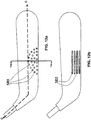
- FIG. 3a illustrates a front view of the external focused weight system 104 illustrated in FIG. 1 (the front view is the view of the external focused weight system 104 as seen from the back side of the blade 103 in FIG. 1 ) depicting in greater detail the arrangement and the shapes of the individual weight components and the encapsulating material.
- the external focused weight system 104 may comprise a center weighted component 302, intermediate weighted components 303 1-2 , and peripheral weighted components 304 1-2 which are encapsulated, partially or entirely, in an encapsulant material 301, such as a polyurethane elastomer.
- weighted components 302-304 may embody or depict a logo or that a logo be inserted within the encapsulate material independently of the weighted components. It is contemplated that the encapsulant material 301 may be visually clear or semi-clear so as to be capable of providing an aesthetic pleasing three-dimensional view of the weighted components 302-304 and/or logo, branding, or other marketing information suspended in the encapsulant. Weighted components 302-304 may be fashioned from any material that has a density substantially greater than the density of the blade 103 and/or the encapsulant material 301.
- a density that is at least 5 or 10 times greater than the density of a core element, resin, or the fibers or the aggregate density of the blade or other composite structure (minus the weighted components) is considered a material that has a substantially greater density.
- Most metals range from 4:54 g/cm 3 (e.g., Titanium) to 21.37 g/cm 3 (e.g., Platinum), with copper, iron, chromium, steel, aluminum bronze, nickel, and some tins ranging from approximately 7 to 9 g/cm 3 and lead at approximately 11.35 g/cm 3
- the matrix or resin based material is selected from a group of resin based materials, including thermoplastics such as polyetherether-ketone, polyphenylene sulfide, polyethylene, polypropylene, urethanes (thermoplastic), and Nylon
- the fibers may be Carbon, Aramid (e.g., KevlarTM), Glass, Polyethylene (e.g., SpectraTM), Ceramic (e.g., NextelTM), Boron, Quartz, Polyester Approx. Density Range - 0.67 - 2.54 g/cc Exemplary Core Elements formulations of expanding syntactic or non-syntactic foam such as polyurethane, PVC, or epoxy, Approx. Density Range - 0.06 - 0.21 g/cc elastomers or rubber, Approx. Density Range - 1.1 g/cc
- a foam core (e.g., ⁇ 0.092g/cm 3 ) composite fiber resin ( ⁇ 1.5 g/cm 3 fiber and resin) blade 103 typically weighs around 115 grams +/-10 grams and has a volume of approximately 165 cm 3 +/-5 cm 3 ) and hence an aggregate density of approximately 0.7 g/cm 3 +/-0.02 g/cm 3 ).
- the weighted components 302-304 may be fashioned from metals such as zinc ( ⁇ 7.13 g/cm 3 ), iron ( ⁇ 7.27 to 7.87 g/cm 3 ), copper ( ⁇ 8.96 g/cm 3 ), nickel ( ⁇ 8.9 g/cm 3 ), steel ( ⁇ 7.8 to 8.0 g/cm 3 ), tin ( ⁇ 5.75 to 7.3 g/cm 3 ), or lead ( ⁇ 11.36 g/cm 3 ) or metal alloys thereof, all of which have greater densities, typically on the order of a magnitude or more than 0.7 g/cm 3 .
- metals such as zinc ( ⁇ 7.13 g/cm 3 ), iron ( ⁇ 7.27 to 7.87 g/cm 3 ), copper ( ⁇ 8.96 g/cm 3 ), nickel ( ⁇ 8.9 g/cm 3 ), steel ( ⁇ 7.8 to 8.0 g/cm 3 ), tin ( ⁇ 5.75 to 7.3 g/cm
- Weighted components formed, entirely or partially, from zinc metal have been found desirable given the relatively low cost per unit mass and the relative high density of zinc. While only a handful of suitable materials for forming weighted components 302-304 are listed above, other high density materials, not limited to metals, are contemplated.
- an external focused weight system 104 may be added to a blade or other composite structure to focus the weight distribution to the region in which it is positioned, it is contemplated that an existing blade or other composite construction may be modified to lighten the weight of the blade 103 or other composite structure so that when the external focused weight system 104 is added, the overall weight of the blade 103 (or other composite structure) remains substantially or approximately the same.
- the additional weight added by the focused weight system 104 may be offset by corresponding reductions in the weight of the composite blade 103 via for example removal of plies in certain regions of the blade, varying the orientation of the fibers, and/or the selection fibers, core elements, and/or resin.
- An external focused weight system 104 having a total weight in the range of 5g to 25g, 5 to 20 grams, 5 to 15 grams, 10 to 20 grams, and 10 to 15 grams are contemplated to be added to a blade.
- An external focused weight system 104 having a total weight of approximately 15g +/- 1g (e.g., weights of 302-304 plus weight of encapsulant material 301) has been found capable of providing a desirable focused weight distribution for blade 103 having a total weight of 115 grams +/- 1 to 15 grams (including the external weight) has been found suitable.
- weighted components 302-304 may be arranged in a symmetrical manner, placing the center of gravity of the external focused weight system 104 in the region of the center weighted component 302.
- the weight values W a , W b , and W c , of a center weighted component 302, an intermediate weighted component 303 1 (or 303 2 ), and a peripheral weighted component 304 1 (or 304 2 ), respectively are relatively characterized by W a > W b > W c .
- FIG. 4 illustrates another contemplated embodiment of an external focused weight system 104 that may provide a desirable focused weight distribution for blade 103.
- the depicted external focused weight system 104 is located in the heel region 411 of blade 103 and comprises weights 402, 403, 404, and 405 encapsulated in an encapsulant material 301.
- the weights 402-405 are not arranged in a symmetrical manner and each weight may have a different weight value.
- the weighted components may be symmetrically or non-symmetrically positioned within the encapsulate material, they may be evenly spaced apart or their spacing may be staggered, uneven, or random, or any combination thereof, they be longitudinally spaced apart or vertically spaced apart or may be spaced apart in depth relative to one another or any combination of spaced arrangement.
- the weighted components may have any suitable or desired shape including circular, rectangular, oval, semi-oval, trapezoidal, triangular, or any combination or group thereof and may taper in thickness toward their outer perimeter or increase in thickness toward their outer perimeter or a combination of increased and decreased thickness extending toward the outer perimeter.
- the weight distribution of the external focused weight system 104 may be uniform, decrease as it extends radially outward or increase as it extends radially outward or have be a combination of such weight distribution.
- an external focused weight system 104 have a relatively high weight distribution near its center region, have a relative high weight distribution near its perimeter region, or have a relatively high weight distribution at both its center and perimeter regions but less so in intermediate regions.
- the space between the weighted components 302-304 is capable of facilitating independent dynamics between the components and yet is also capable of providing for distribution of the focused weight across some or all of the intended impact zone.
- the representative embodiment of the external focused weight system 104 depicted in FIG. 3a - 3b and FIG. 4 - 4a is constructed of multiple weighted components longitudinally spaced apart from one another in an overlapping or staggered manner, it should be understood that there are numerous other contemplated implementations.
- weighted components can be used and indeed its contemplated that there be a single encapsulated weighted component that may be configured as a solid continuous component or may have one or more apertures, open-ended slots, or curvatures therewithin filled or unfilled with the encapsulant material.
- encapsulated material that encapsulates one or more metal or other high density particles, ball-bearings, or flakes or combination thereof and having one or more dimensions either separately or in combination with one or more larger weighted component elements.
- focused weight system 104 is comprised of encapsulated metal or high density particles
- logo or branding information elements perhaps in the form of a 2 or 3 dimensional sheet or film (e.g. made of coated or embossed plastic pr polymer, metallic coated composites), may be inserted within the system 104 to mimic the shape of one or more larger weighted components or otherwise represent the weighted technology component, manufacturer or other branding or marketing information.
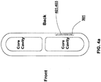
- FIG. 4a illustrates another implementation of an external focused weight system 104.
- the focused weight system 104 and weight components are located generally across the center line of the blade 103 and generally at the heel region 411 of the blade 103.
- some or all of the external focused weight system 104 may be positioned below the centerline and/or above the centerline and that some of the components encompass areas longitudinally anterior and/or posterior to the heel region of the blade.
- the external focused weight system 104 may be positioned entirely or partially in regions other than the heel 411, such as the mid-section 412 or the toe section 413 of the blade 103.
- external focused weight system 104 may be employed in different locations along the length and/or height of the blade 103 and that such external focused weight systems may be varied in weight and/or configuration.
- one focused weight system 104 may be positioned low in the blade (near the ice) while another in the same blade may be positioned above the first system and that the lower system be heavier than the higher component or vice-a-versa.
- multiple focused weight systems 104 and/or weight elements (302-304; 401 - 404) be positioned along the length of the blade 103 either immediately adjacent to each other or longitudinally spaced a defined distance and may have a staggered or overlapping positioning. It is also contemplated that multiple focused weight systems 104 and/or weight elements (302-304; 401-404) may be positioned along the perimeter of one or more desired regions (e.g., specified impact region) to provide for perimeter weighting of the region or regions.
- the representative implementations of the focused weight system 104 illustrated in FIGs. 3 and 4 are each comprised of discrete weighted components that are arranged sufficiently apart from each other in the encapsulant material 301 to be capable of allowing the encapsulant material 301 to flex and deform for example along with the flex in the length of the blade 103 when an external force or stress is encountered.
- the number and the size of the discrete weighted components used in the system may vary depending on the density of the material forming the weighted components.
- the discrete weighted components are fashioned from lead ( ⁇ 11.36 g/cm 3 ), a higher density metal, as opposed to zinc ( ⁇ 7.13 g/cm 3 ), fewer or smaller (or a combination of fewer or smaller) discrete weighted components may be used to achieve the same or a substantially similar focused weight distribution.
- encapsulating less or smaller discrete weighted components in a given encapsulate is capable of providing the external focused weighted system 104 with greater flexibility.
- the use of polymer encapsulated weight elements/components in the form of metal particulates/flakes, or small bearing may provide the desired flexibility, while also providing a more uniform weight distribution.
- FIGs. 5a-5d illustrate the steps of a contemplated process for casting an external focused weight system 104, such as that shown in FIG. 3 .
- FIGs. 5a and 5b illustrate discrete metal weight components 302-304 being placed inside a mold 501. Specifically, the discrete weight components 302-304 are inserted into a preformed cavity 502 having the shape and dimensions of the intended external focused weight system 104. Located within the preformed cavity 502 may be indentations or holes 503 corresponding to aspects of the external shape of the weight components to facilitate arranging and orienting the discrete weighted components 302-304 in a defined manner and spatial relationship within the mold cavity 502 and hence within the external focused weight system 104.
- the weight components may be fully encapsulated with the encapsulate material 301, as illustrated in the profile view of the external focused weight system 104 depicted in FIG. 3b , the discrete weighted components 302-304 may be only partially encapsulated by encapsulant material 301 and that portions (e.g. 311 in the form of a positioning pegs) of the discrete weighted components 302-304 may beyond the boundaries of the encapsulant material.
- the discrete weighted components 302-304 may be set at their intended locations and oriented in a defined manner and spatial relationship within the mold cavity 502 and hence within the external focused weight system 104.
- FIG. 5c illustrates pouring or otherwise positioning the encapsulant material encapsulant material 301 into the preformed cavity 502 with the weight component/elements 302-304.
- the encapsulant material may be in the form of a liquid clear polymer such as a polyurethane that is poured into the preformed cavity 502 with the one or more weight components/elements and cured to create an integral solidified external weight system 104 comprised of weight components (and/or logo/branding or other marketing information) encapsulated within a hardened/cured polymer encapsulant.
- Curing clear PU material may be accelerated with for example at ⁇ 180°F for ⁇ 30 minutes has been found to be a suitable.
- FIG. 5d illustrates the step of removing the cured external focused weight system 104 (having weighted components 302-304 encapsulated in encapsulant material 301) from the mold 501.
- the thickness at the perimeter of the cured system may be thinner or thicker than at the center regions, in other words it is contemplated that the thickness may taper down and/or thicken toward the perimeter or edges of the system 104.
- weight components/elements e.g., 302-304; 401-404.
- the resultant construct can be considered a weighted domed logo, again with the polymer serving as a window to the log and/or weight components.
- the overall flexibility of the weighted blade combination is influenced by the flexibility of the encapsulant material 301 forming the external focused weight system 104. If the encapsulant material 301 chosen is stiffer (i.e., less flexible) than the underlying blade 103, the weighted blade combination becomes stiffer than the underlying blade 103 by itself.
- the weighted blade combination may not feel noticeably different from the underlying blade 103 by itself.
- Translucent polyurethane has been found to be a suitable encapsulant material 301.
- the softness and flexibility of polyurethane works well because it adapts to and flexes with the underlying blade 103 without substantially changing the performance characteristics of underlying blade 103.
- the translucency of the material allows for the desired window into the component weight and/or logo/branding information.
- Shrinkage generally refers to the deformation of a material that results in a reduced volume capacity. Certain materials, such as silicone, exhibit noticeable shrinkage after being heated to a high temperature and then allowed to cool down and hence may not reflect an accurate rendition of the mold 501. Polyurethane has been found to exhibit little or no shrinkage after curing at high temperature.
- the bonding strength between the encapsulant material 301 and the resin material of the underlying blade 103 is important in view of the potentially harsh and forceful impacts that a hockey stick and blade 103 as well as other composite constructs may be subject to. It has been found that a polyurethane encapsulant material 301 is capable of forming a covalent bond or otherwise securely bonds to the resin and/or fibers of the underlying composite construct of the blade 103.
- FIGs: 6a-6i are diagrams of illustrative steps for co-molding the external focused weight system 104 with the blade pre-form 602 to create the externally focused weighted composite blade 103, such as that illustrated in FIGs. 1 and 4 . It should be understood that while this process is describes a co-molding implementation of an external focused weight system 104 to a blade 103, it may be used to co-mold an external focused weight system 104 into any composite construct including for example composite shafts of hockey or lacrosse sticks, composite footwear, skates or shells, or other composite structures, sporting instrument related or otherwise.
- FIG. 6a illustrates an uncured blade pre-form 602 positioned within a first or bottom mold portion 601.
- Mold portion 601 is the portion of the mold that generally defines the front face of the blade.
- the blade pre-form 602 may be constructed by wrapping multiple plies of fibers over one or more core elements and expansion bladder and then applying an uncured resin to the plies of fibers via a resin transfer process.
- One or more of the plies of fibers may be pre-impregnated with resin, the tackiness/adhesiveness of the resin on the pre-impregnated plies (which can be thought of as a tape or tape like substrate) is capable of assisting in forming the lay-up (i.e., positioning the various plies in the desired position and orientation relative to one another as well as the core elements).
- the use of pre-impregnated plies reduces or avoids all together the need to apply additional resin to the plies. As illustrated in FIGs.
- a debossing jig 611 is pressed onto the backside of the blade pre-form 602 in the desired position to create a corresponding cavity 621 on the surface of the backside of the blade pre-form 602.
- the shape and the dimensions of the cavity 621 corresponds to that of the external focused weight system 104.
- the cavity is dimensioned so that when the external focused weight system is inserted therein, the surface transition between the blade pre-form 602 and the external focused weight system 104 is flush or substantially flush. While the use of a jig 611 is described, it is also contemplated that the process may be practiced without a jig.
- the external focused weight system 104 may be incorporated into the blade 103 in a co-molding process wherein the external focused weight system 104 is positioned at the desired location on the blade pre-form construct and then the molding process serves to embed the system 104 into the blade 103.
- the cavity 621 formed on the surface of the blade pre-form 602 may include indentations or holes for receiving the protrusions 311 (see FIG. 3b ) from the back of an external focused weight system 104.
- These indentations or holes for receiving the protrusions may be created by a relief pattern provided on the debossing surface (surface facing the blade pre-form 602) of the debossing jig 611.
- the edges surrounding the debossing jig 611 and the edges of the relief pattern on the imprinting surface may be beveled to prevent damaging the surface of the blade pre-form 602 when the debossing jig 611 is pressed or otherwise applied.
- corresponding indentations or positioning indents or holes may be positioned or created in the blade pre-form as a result of debossing
- the one or more of the molds 601 or 631 may include positioning features such as indentations, holes or other geometrical aspects or features that facilitate the desired positioning of the external focused weight system 104 relative to the blade pre-form construct and the mold elements.
- positioning features e.g., holes, indentations etc
- Co-molding a component e.g., the external focused weight system 104 externally to the composite structure (e.g., blade) whether by use of a Jig or otherwise alters the configuration of the underlying and adjacent composite fiber construct by compressing the core elements and re-configuring the shape of the pre-form construct.
- Such alterations are capable of modifying performance characteristics that would otherwise exist.
- minimizing the thickness and or shape of a focused weight system 104 or other co-molded component can have a corresponding affect in minimizing or otherwise reducing the degree of alteration. For example, tapering the thickness of the edges of the focused weight system 104 or other co-molded component as they extend outward may reduce the in the change in configuration of the underlying composite structure to facilitate a more gradual transition.
- the use of a higher density material to form the weighted components is capable of reducing the dimensions of the system while maintaining the desired weight distribution.
- Forming the focused weight system 104 or other co-molded component in a manner that includes a relatively thin perimeter thickness may also minimize the degree of alteration and create a less abrupt change along the perimeter of the underlying cavity.
- the external focused weight system 104 be comprised of discrete weighted components fabricated from high density metal(s) such as zinc and an overall and/or perimeter thickness of 1-1.65 mm and an overall weight of ⁇ 9 gram +/- 1 gram.
- FIGs. 6f-6g illustrates applying and securing a top mold portion 631 to the bottom mold portion 601 to enclose the uncured blade pre-form 602.
- the blade pre-form 602 may be heated to a high temperature to accelerate the curing process of the blade pre-form 602.
- curing the blade pre-form 602 with the external focused weight system 104 or other co-molded polymer (e.g., polyurethane) component at 300°F may take approximately ⁇ 30- 40 minutes.
- the curing process hardens the resin of the blade pre-form 602 so that the fibers become disposed within a hardened resin matrix while the mold defines the exterior shape of the cured blade 103.
- FIGs. 6h-6i illustrate the steps of separating the top and bottom mold portions, 631 and 601, respectively, after curing and removing the molded and cured focused weighted blade 103 from the mold.
- a clear coat may be applied over the weighted blade 103 to provide a glossy finish.
- the external focused weight system 104 may be cast directly in the cavity 621 of the uncured blade pre-form 602.
- the cavity 621 may serve as the "mold" for forming the external focused weight system 104.
- discrete weighted components 302-304 may be placed and oriented inside the cavity 621, followed by an encapsulant material 301 being applied to the cavity 621 (e.g., pouring clear PU material or other suitable polymer into the cavity 621).
- the blade pre-form 602 may be enclosed by applying and securing a top mold portion 631 and cured at high temperature. In this manner, the resin from the blade pre-form 602 and the encapsulant material 301 are cured and co-molded simultaneously, a process which is capable of forming perhaps a stronger bond between the resin and the encapsulant material 301 and potentially also increasing manufacturing efficiency by among other things reducing production time.
- the external focused weight system or domed logo element may be bonded to a hockey stick blade via an adhesive, such as epoxy glue.
- a cavity may be created on the surface of the composite construct for example on the backside of the hockey stick blade.
- Multiple methods of creating the cavity are contemplated.
- the cavity may be created by employing an insert having the shape and dimensions of the intended external focused weight system and/or branding element. Together with the insert placed at the desired location on the surface of an uncured hockey blade pre-form, both the insert and the blade pre-form may be enclosed by a mold and then heated to accelerate the curing process of the blade pre-form.
- the insert may be removed from the corresponding cavity that has been formed on the surface of the hockey stick blade.
- the corresponding cavity may be formed without using an insert by employing a mold enclosure that already includes a built-in debossing element having the shape and dimensions of the intended external focused weight system.
- adhesive may be administered to one or more inner surfaces of the cavity, followed by inserting the external focused weight system and/or domed logo element into the cavity. Pressure may be applied against the external focused weight system and/or the composite construct, e.g., hockey stick blade, to ensure that a secure bond is formed by the adhesive.
- one or more non-weighted design component may be casted and incorporated onto a composite hockey stick shaft 102.
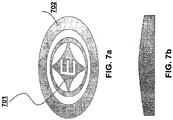
- one or more non-weighted design components such as the logo components 701 and 702 shown in FIG. 7 , may be placed therein in the desired position.
- a design/branding component having an average aggregate density that is substantially the same or less than the density of the encapsulant material 301 may be considered non-weighted.
- a design/branding component having an average aggregate density that is less than the overall average density of the underlying composite structure may also be considered a non-weighted component.
- design/branding components with an aggregate weight that is less than 20 percent of the weight of the encapsulant material, and more preferably 15 percent and even more preferably 10 percent may be considered non-weighted.
- the exemplary co-molding process illustrated in FIGs. 6a-6i may then be employed to incorporate the casted design component into a composite structure such as a hockey stick blade 103 or shaft 102.
- FIGs. 5a-5d and FIGs. 6a-6i may be used to incorporate both weighted and non-weighted components onto any composite construct, including but not limited to sporting instruments such as hockey or lacrosse sticks, footwear such as hockey or sking boots and skates, blade or roller blade holders, helmets, baseball bats, tennis racquets, biking or cycling components, and surfboards and any other composite structure for which branding/marketing and/or focused weight distribution may be found beneficial.
- the non-weighted components may be cast directly in the cavity 621 of the uncured composite construct or structure as in the variation of the co-molding process previously described above.
- the non-weighted design components may be positioned within the cavity in the desired location and the polymer encapsulant poured thereon top and then co-molded and cured with the underlying composite construct. It is also contemplated, however, that the non-weighted design component(s) be positioned within the cavity and/or in the desired location on the uncured composite construct so as to lie adjacent to one or more solid or semi-solid polymer encapsulant elements as opposed to using an liquefied polymer encapsulant.
- the co-molding process would not only result in the encapsulant being bonded to the underlying composite construct but also would result in the encapsulant element being bonded together and/or with the non-weighted design element or component such as that illustrated in FIGs. 7 or 9 .
- the use of solid encapsulant materials that are directly co-molded with the non-weighted or weighted components may allow for the use of different encapsulant materials even within a single externally co-molded component. For example, a semi-translucent or opaque solid or semi-solid encapsulant may be placed in the cavity 621 and then the weighted and/or non-weighted components may be positioned thereon top.
- a translucent/clear solid or liquid polymer for example, may be placed (if solid) or poured (if in liquid form) on top and the entire construct co-molded and cured.
- the externally co-molded component would be formed of multiple formulations of encapsulants, which may be desirable from a marketing or engineering stand point.
- a weighted tape (perhaps with a log or branding thereon) may be used as the weighted component and that either directly inserted into the cavity 621 and co-molded with an encapsulated polymer and composite construct or pre-casted with the polymer as described in connection with FIGs. 5a-5d before being co-molded with the composite construct.
- Yet another aspect of the technology disclosed herein relates to the addition of a weight-adjustable end-plug system 105 to a shaft such as the shaft 102 the shown in FIG. 1 .
- the use of focused weighting systems on sporting or other instrument that during use is swung can facilitate the adjustment of the swing weight of the instrument, e.g. hockey stick 101.
- the swing weight of a sporting good instrument, such as a hockey stick 101 may be characterized as the weight of the instrument/hockey stick as measured from a specified pivot point relative to the end of the shaft often referred to as a fulcrum.
- the pivot point for a hockey stick is the point at which the stick rotates, for instance, when the hockey player makes a slap shot, the pivot point is generally located in the lower-half region of the shaft 102.
- the swing weight of the hockey stick is proportional to the distance between the center of gravity of the hockey stick and pivot point. The farther away the center of gravity is from the pivot point, the greater the swing weight. Because each hockey player generally has his personal style of holding and swinging the hockey stick, the pivot point may vary from one hockey player to another. Consequently, the swing weight of the stick may also vary from one hockey player to another.
- the weight-adjustable end-plug system 105 enables a hockey player to shift the center of gravity, and thus the swing weight vis-à-vis a particular pivot point, of the hockey stick by adding or removing weights from the shaft end of the hockey stick. It is contemplated that the weight-adjustable end-plug system 105 may be used on a hockey stick along with a blade 103 having an external focused weight system 104 as previously described.
- both an external focused weight system 104 on the blade and a weight-adjustable end-plug system 105 to a shaft is capable of facilitating the adjustment of the swing weight to a higher degree than otherwise in that both ends of the hockey stick would have focused weight elements and hence a small adjustment on one end would have a greater impact with respect to adjusting the swing weight relative to a given pivot point.
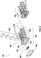
- FIG. 8 illustrates both a disassembled/exploded view and an assembled view of an exemplary embodiment of a weight-adjustable end-plug system 105.
- the weight-adjustable end-plug system 105 comprises an end-plug unit 801, a set of one or more weights 802 1-4 , a logo, branding or design component 803, and an encapsulant material 804.
- Weight-holding part 812 includes one or more compartments or cartridges open ended similar to a slot for inserting weights 802 1-4 , each compartment is designed to securely hold one or more weights.
- the weight-adjustable end-plug system 105 is designed such that the weights 802 1-4 are user-removable, such that the user may add and/or remove weights from the compartments of the weight-holding part 812 to alter the overall weight of the end-plug system 105 and the configuration of the weights therein.
- a "user-removable" component means that a component may be removed from a unit without permanently damaging the unit or the component and that the component was designed to be removed by an ordinary, intended user.
- weights 802 1-4 may be formed of any high density material and in any shape, in one preferred embodiment, the weights 802 1-4 are stainless steel and are formed in a cylindrical shape as illustrated in FIG. 8 . Additionally, the edges on the weights may be beveled to make insertion of the weights into the compartments of the weight-holding unit 812 easier.
- a high density material refers to any material having a density considerably greater than the density of the shaft 102 or than the density of the end-plug unit 801.
- the density of the high density material is at least five or more times greater than the density of the shaft 102 or than the density of the end-plug unit 801. In one embodiment, the density of the high density material is at least ten or more times greater than the density of the shaft 102 or than the density of the end-plug unit 801.
- the weights may be the same or different in mass. The weights may have the same and/or different densities.
- the end-cap part 813 may have a cavity 821 for holding the logo component 803.
- an encapsulant material 804 such as clear PU in liquid form, may be applied to encapsulate the logo component 803 and then cured at high temperature.
- the encapsulant material 804 may be a pre-cured clear PU component that is secured over the logo component 804 inside cavity 821 using an adhesive.
- FIGs. 10a and 10b illustrate cross-sectional views of the weight-holding part 812 of the end-plug unit 801.
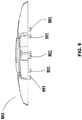
- the weight-holding part 812 features fins 818 that are arranged longitudinally along two opposing surfaces of the weight-holding part 812 and that extend laterally from these opposing surfaces. These fins 818 help to secure the weight-adjustable end-plug system 105 when it is inserted into the shaft 102 of the hockey stick (see FIG. 11 ). While the illustrated implementation shows fins 818 on two opposing surfaces, it should be understood that fins 818 may be included on any or none of the surfaces such that they may be included on one, two, three or all four or more surfaces.
- the fins 818 extending from opposing surfaces span a width W p and a height H p , as depicted in FIG. 10a .
- W p and H p correspond approximately to but are slightly greater than the dimensions W s and H s , respectively, of the inner cavity of the shaft 102 depicted in FIG. 2 .
- W p and H p may be 1% to 5% greater than W s and H s , respectively.
- the fins 818 are capable of flexing and exert outward forces against the inner side walls of the shaft 102, thereby giving rise to static frictional forces that secure the end-plug system 105 to the shaft 103.
- the more the fins flex i.e., bigger W p and H p ), the potentially greater the frictional forces generated.
- increasing the number of fins also increases the frictional forces generated, thereby further securing the end-plug system 105 to the shaft 102.
- the fins also serve to dampen the transfer of forces between the weights secured in the weight-holding part 812 and the shaft 102.
- end-plug system 105 to the shaft 103 is rectangular in shape to correspond to the cross section of a tubular rectangular hockey stick shaft, it should be understood that it may take any shape corresponding to the internal tubular dimensions of the instrument into which it is to be inserted. For example, it may be octagonal to fit within an octagonal lacrosse stick or circular or oval to fit within a tubular opening of baseball or softball bat.
- FIG. 10a further illustrates that each weight compartment is separated from another by a wall 1001, which helps to dampen force transfers between adjacent weights.
- a spine 1002 that runs longitudinally underneath the weight compartments helps to support and secure the weights in their respective compartments/cartridges. As shown, there may be a hole underneath each weight compartment in the spine 1002 that allows the user to eject a secured weight, such as by inserting a rigid instrument through the hole 1003 to push onto and displace the weight through the opening opposite the spine 1002.
- FIG. 10b illustrates cylindrical weighted components 1011 secured within their respective compartments, the cylindrical weighted component 1011 has a diameter D . The cylindrical weighted component 1011 is inserted into its compartment through the opening having a width W o .
- the width of the opening W o is smaller than the diameter D of the cylindrical weighted component 1011.
- the curved side walls 1012 of the opening flex outward, expanding the opening, to accommodate the cylindrical weighted component 1011 as it is being inserted through the opening of the compartment.
- the curved side walls 1012 snap back and return to their original positions to help secure the cylindrical weighted component 1011 once the widest portion of the weight 1011 has bypassed the opening.
- the weight-holding part 812 includes a mechanism for securing an inserted weighted component.
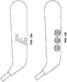
- FIG. 12a illustrates an exemplary array arrangement of concave and/or convex dimpled features 1201 on a hockey blade surface to form a textured hockey stick blade surface.
- Incorporating concave and/or convex features on a composite structure such as the hockey stick blade surface is capable of facilitating the launch of a hockey puck in a potentially more stable and controlled manner.
- the phrase “gear effect” generally refers to the interaction in which one gear is used to turn another gear. For instance, one gear that is turning counterclockwise will turn another gear clockwise and vice versa. A similar effect occurs when a puck is struck by a hockey stick blade surface having concave and/or convex features.
- FIGs. 12b-12-f illustrates other exemplary arrangements of concave and/or convex features on a hockey stick blade surface that are contemplated.
- the concave and/or convex features 1211 may be trenches or raised channels. It should be understood that there are numerous other contemplated implementations.
- FIG. 13a provides a cross-sectional view (taken at line 13a ----- 13a) of the hockey stick blade in FIG. 12a , including concave dimpled features 1201 that are filled in using a filler material 1322, such as a polyurethane (PU) material.
- PU polyurethane
- PU has been found to be a suitable material because it tends to be softer and less stiff relative to both a conventional puck and the hardened epoxy resin surface of a composite hockey stick blade.
- the puck is able to "dig" into the PU filler material, which may serve to enhance the gripping mechanism of the hockey stick blade.
- PU also tends to form a durable and strong bond with the epoxy resin material of a composite hockey stick blade surface.
- a desirable filler material should not significantly affect the overall stiffness of the hockey stick blade. While PU has been found suitable, it is contemplated that other polymer materials may be used including, for example, Surlyn.
- each of the dimpled features in FIG. 13a is depicted as having the same size and dimension, it is contemplated that each individual concave and/or concave feature may have a different size and/or dimension.
- the heights h of the convex dimpled features or the depth d of the concave dimpled features may range from 0.5 mm to 2.5 mm.
- a combination or sub-combination of unfilled concave features, filled-in concave features (e.g., PU filled), and/or convex features may be incorporated in one or more arrangements on a hockey stick blade surface, for instance, to optimize or to achieve a desirable gear effect. As shown in FIG.
- concave features may be created on a hockey stick blade surface by including corresponding debossing elements 1322 in a mold 1321 that is used during the curing of the hockey stick blade pre-form.
- FIG. 13c illustrates that convex features may be similarly created on a hockey stick blade surface by including corresponding embossing elements 1332 in a mold 1331.
- a plastic compression bladder may be placed inside the core cavity of the blade pre-form to provide sufficient outward pressure for forming the concave and/or convex features on the hockey stick blade surface.
- FIG. 14a illustrates the moment of impact between a hockey puck 1401 and a hockey blade 1402 having exemplary convex dimpled features on its front surface.
- the linear and rotational velocities of the puck may be illustrated by corresponding velocity vectors.
- FIG. 14b illustrates an exemplary view of the contact surface area 1411 of when the hockey puck 1401 strikes the hockey stick blade 1402 having convex features 1412, according to one embodiment.
- the width W puck of the contact surface area 1401 is determined by the relative velocities of the puck and hockey stick blade immediately before impact. During impact, the initial impact region of the puck may deform and widen against the hockey stick blade to form the contact surface area 1411. The greater the impact (i.e., greater relative velocities), the greater the potential deformity and the wider the contact surface area 1411 becomes.
- the sizes and spatial arrangement of the concave and/or convex features should be designed relative to the dimensions of the contact surface area. For instance, if the features are too big, the puck may only make contact with the features 1412 and not with the underlying hockey stick blade surface 1413.
- the puck may only make contact with the underlying blade surface 1413 and not with the features 1412. If the features 1412 are too small, the features 1412 may enhance the friction mechanism between the puck and the blade surface rather than the gear effect.
- the arrangement of the array may vary in numerous respects.
- the dimples may be symmetrically arranged or non-symmetrically arranged.
- the dimple array may be located longitudinally at the center of the blade, at the heel or tip of the blade or any combination thereof.
- the dimple array may located vertically above the centerline of the blade face, below the center line of the blade face or overlap the centerline of the blade face or any combination thereof.
- the dimple array may be arranged in a circular fashion, a semi-circular fashion, a rectangular or trapezoidal fashion, and/or any other geometry or combinations of geometries.
- the dimple arrays on the front face of the blade may be the same or different than those on the back face of the blade.
- the back face of the blade may have fewer or no dimple arrays relative to the front face of the blade or vice versa.
Landscapes
- Health & Medical Sciences (AREA)
- General Health & Medical Sciences (AREA)
- Physical Education & Sports Medicine (AREA)
- Chemical & Material Sciences (AREA)
- Engineering & Computer Science (AREA)
- Composite Materials (AREA)
- Mechanical Engineering (AREA)
- Casting Or Compression Moulding Of Plastics Or The Like (AREA)
- Moulding By Coating Moulds (AREA)
- Golf Clubs (AREA)
- Laminated Bodies (AREA)
- Road Signs Or Road Markings (AREA)
Description
- The field of the present invention generally relates to composite structures including sporting implements such as hockey sticks and component structures thereof.
- Composite structures are generally comprised of fibers (aligned in one or more defined orientations and/or randomly oriented) disposed within a hardened resin matrix. Their manufacture typically involves overlaying one or more plies of fibers in a desired manner relative to one another to create an uncured pre-form construct. The pre-form construct is then cured using a mold (e.g., external and/or internal molds) and perhaps a compression or expansion bladder to facilitate the curing and molding process. The curing process hardens the resin, which is either impregnated on the fibers or transferred into the mold. The molding process, sometimes with the assistance of a bladder, defines the external shape of the composite structure. Once cured the hardened external surfaces of the composite structure may be finished using paint and/or by applying decals (typically in the form of a thin sheet or film) to provide the desired branding, look and finish. Notably, such finishing processes are applied to the hardened surface of the composite structure and are not integrated or incorporated into the molding process.
- Composite hockey sticks, like traditional wood hockey sticks, are generally comprised of a blade portion and an elongated shaft portion. The shaft, however, unlike traditional wood hockey sticks is tubular and can be either detachable or permanently attached to the blade. Conventional composite hockey stick shafts are typically either constructed via an automated pull-trusion process or a hand wrapping process. In the pull-trusion process a pulltrusion machine wraps fibers soaked in resin over a mandrel that that is then fed into a die and heating element to cure the resin and hardened the shaft. The hardened shaft is cut into the desired segments as its is pulled off the mandrel. The hand wrapping process involves wrapping/overlaying a mandrel of suitable dimension with plies of fibers and a resin in the desired locations to create an uncured shaft pre-form that is then cured. Typically, the curing process involves placing the mandrel and uncured shaft pre-form within a tubular compression bladder that is further inserted within a heating compartment. The heat and compression exerted by the bladder on the composite pre-form serves to mold and cure the shaft, which upon cooling results in the fibers being compressed into the shape of the mandrel and disposed in a hardened resin matrix. The mandrel is then removed by sliding it out of one end of the cured tubular shaft. The hardened tubular composite shaft may be further processed (sanded, painted, decaled, etc.) and then either sold separately or mated to a detachable or permanently attached blade and sold as a complete hockey stick unit. Notably, the finishing process including the decaling and paint are applied to the hardened surface of the cured composite structure and are not incorporated into the molding process. A wood or plastic end cap of fixed weight and configuration is sometimes used to cap the top end of the tubular shaft.
- Similarly, contemporary composite hockey stick blades are typically constructed by wrapping multiple plies of fibers over one or more core elements to create a hockey stick blade pre-form. The blade pre-form is then placed within an external mold where the resin, which is either pre-impregnated on the fiber plies or added via a resin transfer process, is cured. An expansion bladder internal within the blade pre-form or one or more heat expanding core elements provides internal pressure to mold the blade into the shape of the external mold. The curing process hardens the resin so that the fibers become disposed within a hardened resin matrix while the mold defines the exterior shape of the cured blade. Once molded and cured the blade may be further finished by deburring and perhaps with a coat of paint or exterior decals or the like and is then sold separately or as a hockey stick unit as previously described. Notably, the finishing process including the decaling and paint are applied to the hardened surface of the cured composite structure and are not incorporated into the molding process. Moreover, the front and back surfaces of the blade are typically smooth with uniform texture to mimic the surface of a traditional wood hockey stick.
- Typically the hockey stick blade is attached to the shaft via a "tennon" or "hosel" section, which is generally comprised of an upward extension of the blade from the heel and is dimensioned at its upper end to be slidably and snugly received within a generally rectangular lower tubular end of the shaft. The shaft or a connection member may also be mated to the blade via a tongue and groove type arrangement located at the heel. Such hockey stick constructions and joints are disclosed in commonly owned
U.S. Patent Nos. 7,097,577 and7,144,343 . - Once cured, composite shafts and blades are typically not further processed other than in the way of exterior finishing steps like deburring, painting, decaling with thin sheets or films, and assembly. Consequently, the weight distribution of the stick therefore is primarily determined by the fiber ply lay-up, the resin distribution, and in the case of the blade the core elements. Moreover the decaling primarily consisted of applying a sticker of a logo or painting a name or logo on the cured component.
- While such composite constructs have found wide acceptance world-wide, until now there has been little or no attention directed to engineering the weight distribution of hockey sticks by positioning focused weights externally in discrete locations of the blade or shaft and/or the use of an adjustable or modularly weighted focused-weighted end-plug or cap on the end of a tubular (composite or otherwise) hockey stick shaft. Furthermore, until now there has been little or no attention directed to co-molding weighted and/or non-weighted elements and/or logos/information into the external surfaces of a composite structure capable of providing a focused weight distribution while also providing an appealing visible technology to the user. In addition, until now there has been little or nor attention directed to adhesively attaching weighted elements and/or weighted logos/branding information to the external surfaces of a composite structure or to do so within a cavity formed on the outer surface of the composite structure. Moreover, until now there has been little or no attention directed to engineering the texture of the composite blade surface to create a non-smooth or nonuniform texture throughout one or both sides of the blade and/or in discrete regions of one or both sides of the blade or to do so using arrays of convex and/or concave dimple arrangements that are capable of increasing the rotational speed of the puck, which in turn is capable of creating a more stable and controllable launch condition. From
e.g. CA 2 256 157 A1 a hockey stick blade with a control fascia is known. The known hockey stick blade includes a composite hockey stick blade and a logo system co-molded to an external surface of the cured composite hockey stick blade. -
US 2001046909 A1 also discloses a hockey stick. - The present invention provides a hockey stick blade system according to
claim 1 and a co-molding process for forming a hockey stick blade system according to claim 9. Further embodiments of the system and the process are described in the respective dependent claims. Hence, the present inventive technology relates to composite structures including hockey sticks, their manufacture, configuration and component structures. Various aspects are set forth below. - One aspect not belonging to the invention is directed to a composite structure such as hockey stick blades constructed of fibers disposed within a hardened resin matrix encapsulating one or more core elements such as a light foam (e.g., polyurethane foam), wherein the blade further includes one or more high density components (e.g. metal) positioned externally on the blade. The high density components may be positioned on the front or back of the blade at the heel region or other regions of the blade such as the mid section or toe region thereby creating a focused weight distribution on the blade. A polyurethane elastomer or some other suitable polymer or material may encapsulate the high density components, for instance, to serve as a means to secure the high density components relative to one another and/or in the desired location on the blade. Branding, logo, or other information may be incorporated with the high density element and may also be encapsulated within the polymer. The information may be part of the high density element and/or separate therefrom. The encapsulating polymer may be clear or translucent throughout the component or in one or more regions to allow the high density weights and/or the logo/branding/information to be suitably visible to the user to the extent desired. For example, when both high density component(s) and logo/branding/information elements are encapsulated within the polymer to create a weighted domed logo assembly that is comprised of embedded weights in combination with a logo, such a construct is capable of providing both a desired focused weight distribution as well as appealing and visible branding of the technology to the user in a desirable appearance.
- Another aspect of the invention is directed to composite structure such as a hockey stick blade constructed of fibers disposed within a hardened resin matrix encapsulating one or more core elements such as a light foam (e.g., Corecell A300 of Gurit at 0.06 g/cc density, Alcan Airex C71.55 at 0.06 g/cc (a polyvinyl-chloride rigid foam), balsa wood at 0.065 g/cc, or other engineered light weight foams), wherein the composite structure or blade further includes one or more non-weighted logo/branding components co-molded externally thereto. The non-weighted logo/branding components may be positioned on the front or back of the blade at the heel, center and/or toe regions of the blade. A polyurethane elastomer or some other suitable polymer or material may encapsulate the non-weighted logo components, for instance, to serve as a means to secure the non-weighted logo components in the desired location on the composite structure (e.g., hockey stick blade or other sporting good composite instrument). The encapsulating polymer may be translucent to allow the branding/logo information to be seen by the user.
- Another aspect not belonging to the invention is directed to a co-molding process for making the hockey stick blade having an external focused weight system (and/or a non-weighted logo/branding system) that includes providing an uncured composite pre-form such as hockey stick blade pre-form and positioning an encapsulated high density system (external focused weighted system) in a cavity on the surface of the uncured pre-form at the desired location. The high density components may be encapsulated with a suitable polymer such as polyurethane elastomer to form the encapsulated high density system. The encapsulated high density system may be secured to the underlying composite blade through high temperature curing. The encapsulating polymer or polyurethane elastomer may serve as a vibration dampener as well as to provide additional weight to the external focused weight system. The various configurations, materials and implementations of the high density components constitute yet another aspect of the inventive technology disclosed.
- Another aspect not belonging to the invention is directed to other process by which an external focused weight system (or a non-weighted logo/branding system) may be incorporated into a composite structure. Such processes include creating a cavity that is later filled with an external focused weight system (or a non-weighted logo/branding system) either before or after the composite structure is cured. The specific manner by which the external focused weight system (or a non-weighted logo/branding system) is incorporated into the cavity, is also an aspect of the inventive technology herein.
- Another aspect not belonging to the invention is directed to a weight-adjustable end-plug dimensioned to be insertable into a tubular shaft, such as a hockey stick. The weight-adjustable end-plug includes an end-plug unit and one or more weighted components insertable into the end-plug unit. The end-plug unit may include one or more chambers to receive and secure the one or more weighted components. The end-plug unit may also include multiple fins that extend laterally from opposing surfaces of the end-plug unit. Once the weight-adjustable end-plug unit is inserted into a tubular hockey stick shaft, the multiple fins flex against the side walls of the hockey stick shaft to secure the weight-adjustable end-plug in its position. The weight-adjustable end-plug allows a hockey player to add and remove weights from the end of the hockey stick shaft and thereby adjust the swing weight of the hockey stick.
- Yet another aspect not belonging to the invention is directed to hockey sticks having an external focused weight system (and/or a non-weighted logo/branding system) co-molded or otherwise incorporated into a composite blade, a tubular shaft, and a weight-adjustable end-plug as described above and methods for making such hockey sticks. The stick may be a two part stick with a detachable blade or a blade that is permanently attached. It is contemplated that approximately an equal amount of weight may be added to the shaft (via weight-adjustable end-plug) and to the blade (via external focused weight system). It is also contemplated that existing composite hockey stick shafts and blade constructs may be made lighter (using fewer plies in certain regions of the constructs) and the weight saved in lightening the construct be added back as external focused weight system as described above, such that the total weight of the shaft, blade or hockey stick remains the same or substantially the same as it did before.
- Yet another aspect not belonging to the invention is directed to the incorporation of dimple arrays on the surface of a composite structure, such as a composite hockey stick blade. The arrays may be co-molded into the composite structure and may be convex, concave or a combination thereof The dimples may have the same or different geometries and the arrangement of the array may be uniform or may vary in numerous respects throughout the composite structure or within a region or regions thereof. For example, the dimples may be symmetrically arranged or non-symmetrically arranged. The dimple array may be located longitudinally at the center of the blade or composite structure, at the heel or tip of the blade or composite construct or any combination thereof. The dimple array may be located vertically above, below, and/or overlap the centerline of the blade (i.e., the line that bisects the upper 1/2 portion of the blade from the lower 1/2 portion) or composite construct. The dimple array may be arranged in a circular fashion, a semi-circular fashion, a rectangular or trapezoidal fashion, and/or any other geometry or combinations of geometries. The dimple array on one face of the composite structure may be the same or different than the dimple face on another face. For example in a composite hockey stick blade implementation, the back face of the blade may have fewer or no dimple arrays relative to the front face of the blade or vice versa.
- Additional implementations, features, variations and advantageous of the invention will be set forth in the description that follows, and will be further evident from the illustrations set forth in the accompanying drawings.
- The accompanying drawings illustrate presently contemplated implementations of the inventive technology and, together with the description, serve to explain various principles of the technology disclosed herein.
-
FIG. 1 illustrates a hockey stick that embodies certain aspects not belonging to the invention. Specifically,FIG. 1 illustrates an assembled and a disassembled representative hockey stick having a hollow tubular shaft, a replaceable or detachable composite blade that includes a co-molded external focused weight system, and a removable, weight-adjustable end-plug system. -
FIG. 2 illustrates a cross-sectional view of the tubular hockey stick shaft such as that depicted inFIG. 1 . -
FIG. 3a is a front view illustration of the external focused weight system illustrated inFIG. 1 depicting in greater detail the arrangement and the shapes of the individual weights and encapsulating material of an illustrative embodiment. -
FIG. 3b is a side profile view of the illustrative external focused weight system depicted inFIG. 3a . -
FIG. 4 illustrates another illustrative implementation of an external focused weight system not belonging to the invention and being positioned positioned on the backside of a detachable hockey stick blade at the heel region depicting an alternative arrangement and shapes of weighted elements and encapsulating material. -
FIG. 4a is a simple diagram that illustrates a cross-sectional view of the hockey stick blade taken alonglines 4a----4a ofFIG. 4 . -
FIGs. 5a-5d illustrate steps of a representative not belonging to the invention for casting an external focused weight system, such as that shown inFIG. 3 andFig. 4 wherein the weighted elements are positioned within a mold configured to define the exterior shape and dimensions of the focused weight system and then covered with a polymer such as a polyurethane that upon solidifying encapsulates the weighted elements and logo or branding information therein included. This process may also be used to cast non-weighted encapsulated logo or branding elements (with or without weighted components). -
FIGs. 6a-6i illustrate steps of a representative process not belonging to the invention for co-molding an external focused weight system onto an underlying composite structure in the form of exemplary hockey stick blade such as that depicted inFIGs. 1 and4 , wherein the uncured composite pre-form construct is positioned within a mold and embossed using a suitably designed and configured jig, then the external focused weighted system is positioned within the cavity created by the embossing and the entire assembly is cured within the mold so that the pre-form construct and focused weight system are co-molded. -
FIGs. 7a and 7b illustrate a front and side view of an non-weighted logo or branding component according to the invention and that is capable of being co-molded into a composite construct such as that illustrated inFIG. 9 and as described in the representative co-molding process illustrated inFIGs: 6a-6i . -
FIG. 8 is a more detailed illustration of a modular weight-adjustable end-plug system illustrated in the hockey stick depicted inFIG. 1 and includes both an exploded and assembled views of an exemplary implementation of the weight-adjustable end-plug system. -
FIG. 9 provides a top profile view of an exemplary logo component that may be encapsulated in the end-cap part of the weight-adjustable end-plug system or that may be co-molded (with or without being first encapsulated within a polymer) into a composite construct as described in the representative co-molding process illustrated inFIGs: 6a-6i .. -
FIGs. 10a and 10b provide cross-sectional views of the end-plug system depicted inFIG. 8 and11 without and with weights inserted therein. -
FIG. 11 illustrates an exemplary weight-adjustable end-plug system inserted into the top end of a tubular hockey stick shaft such as that depicted inFIGs. 1 and2 with the internal corners of the shaft depicted in shadow. -
FIGs. 12a-12f illustrate exemplary concave and/or convex features arranged on a hockey stick blade. -
FIG. 13a illustrates the side profile view of the hockey stick blade inFIG. 12a , taken alonglines 13a----13a, that includes exemplary concave features that are filled with a filler material.FIGs. 13b and 13c illustrate side profile views of exemplary hockey stick blades having concave/convex features that are formed from corresponding molds having debossing/embossing features. -
FIG. 14a illustrates the moment of impact between a hockey puck and a hockey blade having exemplary convex dimpled features on its front surface.FIG. 14b illustrates an exemplary view of the contact surface area of when the hockey puck strikes the hockey stick blade having convex features -
FIG. 1 illustrates both an assembled view and a disassembled view of a representativecomposite hockey stick 101 comprising ashaft 102, ablade 103 with externalfocused weight system 104, and a removable, weight-adjustable end-plug system 105. Theshaft 102 may be detachable from theblade 103 at its lower end as illustrated inFIG. 1 or may be permanently attached. The joint between theshaft 102 andblade 103 may be comprised of a suitably dimensionedconnection member 106 located on the upper-end of the blade 103 (often referred to as a "hosel" or "tennon") that is received within asocket 107 of thelower end shaft 102 as shown inFIG. 1 . It should be understood that any number of other connection types, including for example those disclosed in commonly owned patents7,097,577 7,144,343 - The
blade 103 can be made via a process that generally involves the following steps. First, one or more core elements (such as foam) are wrapped with plies of fibers disposed in an unhardened resin in a desired lay-up. As illustrated in FIGs. 16A-16C of co-ownedU.S. patent no. 7,097,577 and the corresponding description and blade configurations illustrated 14A-A4F, the core elements are often comprised of an upper and lower element and the plies are often wrapped between the elements to encapsulate the core elements. The core elements may be made of foam such as formulations of expanding syntactic or non-syntact foam such as polyurethane, PVC, epoxy, or any other suitable material. One or more of the core elements either in combination with another type of core element or separately may be made of an elastic material such as rubber or polyurethane rubber. It should be understood that other suitable material capable of bonding with the resin/ fiber while providing suitable durability for the core of the composite sandwich structure may also be used. Together, the one or more core elements are generally in the form of ahockey stick blade 103. An expansion bladder (for example made of plastic is may also be inserted between the wrapped and upper and lower core elements and then the entire blade pre-form construct is further wrapped within additional plies of fibers such that the plastic bladder is encapsulated within plies of fibers. Using epoxy based pre-impregnated plies of fibers, such as 34/700 manufactured by Grafil, Inc. works well in that the adhesive properties of the plies can serve to keep the pre-form structure together as it is being constructed. A suitable plastic bladder material includes a nylon bladder made by Airtech International. It has also been found that a core element made of PVC foam when used with such an expansion bladder is capable of providing suitable results. Once all the plies are layered over the core elements and bladder the entire construct is placed within a female mold having the desired exterior shape of the blade and is cured via application of heat for an appropriate time, temperature and pressure. The plastic bladder is positioned such that the end of the plastic bladder extends out the hosel (e.g., at the top end surface of the hosel) of the blade pre-form and prior to curing is connected to a nozzle that channels pressurized air into the bladder while the blade is being cured. The pressurized air within the bladder serves to provide internal pressure that assists in ensuring that the plies of fibers are tightly compacted and that the blade pre-form takes on an accurate rendition of the mold as it is cured. As explained in is explained in detail below in connection withFIGs. 3-7 below, the external focusedweight system 104 or other non-weighted logo/branding/information component can be incorporated into the outer surface of the blade or other composite structure. - The
shaft 102 is tubular and may be constructed of fibers disposed within a hardened resin matrix. The fibers may be aligned and oriented in one or more defined directions in one or more different layers and may include an outer layer a woven fiber. Various fibers may be employed including carbon, aramid (e.g., Kevlar™), boron, glass, etc.FIG. 2 provides a cross-sectional view of theshaft 102 depicted inFIG. 1 and is illustrative of the construction of theshaft 102 including representative layers offibers outer layer 202, and the tubular hollow 203 of theshaft 102. The lay-up and the dimensions of the hollow 203 may vary as it extends the length of theshaft 102. For example, additional or few plies of fibers may be added or removed from a given region or oriented in a manner to provide the adequate strength and flexibility. Similarly, the hollow and external dimensions of the shaft may vary for example narrow in one or more directions as it extends toward the blade end of theshaft 102. - Typically, as described in the background of this application, composite shafts may be formed either (1) via wrapping plies over a mandrel and then curing (2) via bladder molded process or (3) via a pull-trusion process. The pull-trusion method is typically automated as compared to the wrapping method, which is typically done by hand. In addition, the pull-trusion method typically employs a uniformly dimensioned mandrel which results in a uniform shaft that does not vary in dimension along its longitudinal length. The wrapped construction method allows for variations along the shaft both in construction (e.g., ply lay-up at any given region of the shaft may be varied as needed) and internal and external dimension (e.g., a shaft typically has a tapered internal and external configuration as it extends toward the blade). Thus in a wrapped construction where the mandrel is tapered as it extends downward to the connection with the blade, the mandrel is typically removed from the upper-end (butt) of the shaft because the blade-end (tip) of the shaft is too narrow to allow the larger dimensioned upper regions of the mandrel to pass. While composite tubular shafts have been described, it is also contemplated that the
shaft 102 may be constructed of non-fiber reinforced plastic or other material suitable of forming a tubular shaft construct capable of receiving an end-plug and/or blade connection such as aluminum or other suitable metal or may be constructed of a combination of metal and fiber composite. - As a general proposition, a hockey puck gains its velocity and direction as a result of impact mechanism with the blade as it is maneuvered by a hockey player. The impact mechanism which involves transfer of energy from the hockey stick to the puck determines the puck's velocity and trajectory. The impact force on the puck, which is generally a product of the mass and velocity of the striking instrument (i.e., hockey stick) at the point of impact is an important component in the energy transfer to the puck. The addition of an external
focused weight system 104 on the blade at one or more strategic location(s) is capable of customizing or enhancing the effective mass of the blade at one or more given regions and thereby tailor the characteristic of the puck launching condition. For example, as illustrated inFIGs. 1 and4 , focused weight may be added to, near, or across the heel region of the blade. The heel region of the blade is generally configured or constructed to be stiffer than the toe region in that the toe is typically thinner than the heel area. The heel region also resides between the majority of the blade face and the shaft where the players' hands are in contact. Thus, forces on the blade generally pass through the heel before they reach the players hands and conversely forces exerted by the player on the shaft generally are transferred to the blade through the heel. The heel region is also generally encompassed within or near the region in which high impact shots are taken. Thus, positioning an externalfocus weight system 104 at, near or across the heel region situates the system to facilitate curtailing/dampening unwanted vibration while also proximal to the regions where high impact shots are taken thereby capable of enhancing the effective force impact on the puck. -
FIG. 3a illustrates a front view of the external focusedweight system 104 illustrated inFIG. 1 (the front view is the view of the external focusedweight system 104 as seen from the back side of theblade 103 inFIG. 1 ) depicting in greater detail the arrangement and the shapes of the individual weight components and the encapsulating material. As shown, the external focusedweight system 104 may comprise a centerweighted component 302, intermediateweighted components 3031-2, and peripheralweighted components 3041-2 which are encapsulated, partially or entirely, in anencapsulant material 301, such as a polyurethane elastomer. It is contemplated that one or more of the weighted components 302-304 may embody or depict a logo or that a logo be inserted within the encapsulate material independently of the weighted components. It is contemplated that theencapsulant material 301 may be visually clear or semi-clear so as to be capable of providing an aesthetic pleasing three-dimensional view of the weighted components 302-304 and/or logo, branding, or other marketing information suspended in the encapsulant. Weighted components 302-304 may be fashioned from any material that has a density substantially greater than the density of theblade 103 and/or theencapsulant material 301. For example, a density that is at least 5 or 10 times greater than the density of a core element, resin, or the fibers or the aggregate density of the blade or other composite structure (minus the weighted components) is considered a material that has a substantially greater density. Most metals range from 4:54 g/cm3 (e.g., Titanium) to 21.37 g/cm3 (e.g., Platinum), with copper, iron, chromium, steel, aluminum bronze, nickel, and some tins ranging from approximately 7 to 9 g/cm3 and lead at approximately 11.35 g/cm3 The table below provides some approximate density ranges for representative resin, fiber, and core materials used to manufacture composite structures:Material Density [g/cm 3 ] Exemplary Resins The matrix or resin based material is selected from a group of resin based materials, including thermoplastics such as polyetherether-ketone, polyphenylene sulfide, polyethylene, polypropylene, urethanes (thermoplastic), and Nylon-6 and thermosets such as urethanes (thermosetting), epoxy, vinylester, polycyanate, and polyester. Approx. Density Range - 0.75 - 1.52 g/cc Exemplary Fibers The fibers may be Carbon, Aramid (e.g., Kevlar™), Glass, Polyethylene (e.g., Spectra™), Ceramic (e.g., Nextel™), Boron, Quartz, Polyester Approx. Density Range - 0.67 - 2.54 g/cc Exemplary Core Elements formulations of expanding syntactic or non-syntactic foam such as polyurethane, PVC, or epoxy, Approx. Density Range - 0.06 - 0.21 g/cc elastomers or rubber, Approx. Density Range - 1.1 g/cc - A foam core (e.g., ∼0.092g/cm3) composite fiber resin (∼1.5 g/cm3 fiber and resin)
blade 103 typically weighs around 115 grams +/-10 grams and has a volume of approximately 165 cm3 +/-5 cm3) and hence an aggregate density of approximately 0.7 g/cm3 +/-0.02 g/cm3). In such a case, the weighted components 302-304 may be fashioned from metals such as zinc (∼7.13 g/cm3), iron (∼7.27 to 7.87 g/cm3), copper (∼8.96 g/cm3), nickel (∼8.9 g/cm3), steel (∼7.8 to 8.0 g/cm3), tin (∼5.75 to 7.3 g/cm3), or lead (∼11.36 g/cm3) or metal alloys thereof, all of which have greater densities, typically on the order of a magnitude or more than 0.7 g/cm3. Weighted components formed, entirely or partially, from zinc metal have been found desirable given the relatively low cost per unit mass and the relative high density of zinc. While only a handful of suitable materials for forming weighted components 302-304 are listed above, other high density materials, not limited to metals, are contemplated. - While the addition of an external
focused weight system 104 may be added to a blade or other composite structure to focus the weight distribution to the region in which it is positioned, it is contemplated that an existing blade or other composite construction may be modified to lighten the weight of theblade 103 or other composite structure so that when the external focusedweight system 104 is added, the overall weight of the blade 103 (or other composite structure) remains substantially or approximately the same. For instance, the additional weight added by the focusedweight system 104 may be offset by corresponding reductions in the weight of thecomposite blade 103 via for example removal of plies in certain regions of the blade, varying the orientation of the fibers, and/or the selection fibers, core elements, and/or resin. An external focusedweight system 104 having a total weight in the range of 5g to 25g, 5 to 20 grams, 5 to 15 grams, 10 to 20 grams, and 10 to 15 grams are contemplated to be added to a blade. An external focusedweight system 104 having a total weight of approximately 15g +/- 1g (e.g., weights of 302-304 plus weight of encapsulant material 301) has been found capable of providing a desirable focused weight distribution forblade 103 having a total weight of 115 grams +/- 1 to 15 grams (including the external weight) has been found suitable. - As
FIG. 3a illustrates, weighted components 302-304 may be arranged in a symmetrical manner, placing the center of gravity of the external focusedweight system 104 in the region of the centerweighted component 302. In one embodiment, the weight values Wa , Wb , and Wc , of a centerweighted component 302, an intermediate weighted component 3031 (or 3032), and a peripheral weighted component 3041 (or 3042), respectively, are relatively characterized by Wa >Wb >Wc . Although this relative weight configuration works well to provide a desirable focused weight distribution forblade 103, other relative weight configurations are contemplated.FIG. 4 illustrates another contemplated embodiment of an externalfocused weight system 104 that may provide a desirable focused weight distribution forblade 103. The depicted external focusedweight system 104 is located in theheel region 411 ofblade 103 and comprisesweights encapsulant material 301. In this embodiment, the weights 402-405 are not arranged in a symmetrical manner and each weight may have a different weight value. Thus, it is contemplated that the weighted components may be symmetrically or non-symmetrically positioned within the encapsulate material, they may be evenly spaced apart or their spacing may be staggered, uneven, or random, or any combination thereof, they be longitudinally spaced apart or vertically spaced apart or may be spaced apart in depth relative to one another or any combination of spaced arrangement. Moreover, the weighted components may have any suitable or desired shape including circular, rectangular, oval, semi-oval, trapezoidal, triangular, or any combination or group thereof and may taper in thickness toward their outer perimeter or increase in thickness toward their outer perimeter or a combination of increased and decreased thickness extending toward the outer perimeter. In addition, when multiple discrete weight components or elements are employed, the weight distribution of the external focusedweight system 104 may be uniform, decrease as it extends radially outward or increase as it extends radially outward or have be a combination of such weight distribution. For example, it is contemplated that an externalfocused weight system 104 have a relatively high weight distribution near its center region, have a relative high weight distribution near its perimeter region, or have a relatively high weight distribution at both its center and perimeter regions but less so in intermediate regions. - Notably, the space between the weighted components 302-304 is capable of facilitating independent dynamics between the components and yet is also capable of providing for distribution of the focused weight across some or all of the intended impact zone. Notably, while the representative embodiment of the external focused
weight system 104 depicted inFIG. 3a - 3b andFIG. 4 - 4a is constructed of multiple weighted components longitudinally spaced apart from one another in an overlapping or staggered manner, it should be understood that there are numerous other contemplated implementations. For example it is contemplated, that fewer or greater numbers of weighted components can be used and indeed its contemplated that there be a single encapsulated weighted component that may be configured as a solid continuous component or may have one or more apertures, open-ended slots, or curvatures therewithin filled or unfilled with the encapsulant material. Yet another contemplated implementation of the focusedweight system 104 includes an encapsulated material that encapsulates one or more metal or other high density particles, ball-bearings, or flakes or combination thereof and having one or more dimensions either separately or in combination with one or more larger weighted component elements. In the case wherefocused weight system 104 is comprised of encapsulated metal or high density particles, logo or branding information elements perhaps in the form of a 2 or 3 dimensional sheet or film (e.g. made of coated or embossed plastic pr polymer, metallic coated composites), may be inserted within thesystem 104 to mimic the shape of one or more larger weighted components or otherwise represent the weighted technology component, manufacturer or other branding or marketing information. - By example
FIG. 4a illustrates another implementation of an externalfocused weight system 104. Notably, as illustrated therein, the focusedweight system 104 and weight components are located generally across the center line of theblade 103 and generally at theheel region 411 of theblade 103. It is contemplated that some or all of the external focusedweight system 104 may be positioned below the centerline and/or above the centerline and that some of the components encompass areas longitudinally anterior and/or posterior to the heel region of the blade. Hence, it is contemplated that the external focusedweight system 104 may be positioned entirely or partially in regions other than theheel 411, such as the mid-section 412 or thetoe section 413 of theblade 103. Further it should be understood that while a single externalfocused weight system 104 is illustrated, it is contemplated that multiple external focusedweight systems 104 may be employed in different locations along the length and/or height of theblade 103 and that such external focused weight systems may be varied in weight and/or configuration. For example, it is contemplated that one focusedweight system 104 may be positioned low in the blade (near the ice) while another in the same blade may be positioned above the first system and that the lower system be heavier than the higher component or vice-a-versa. It is also contemplated that multiple focusedweight systems 104 and/or weight elements (302-304; 401 - 404) be positioned along the length of theblade 103 either immediately adjacent to each other or longitudinally spaced a defined distance and may have a staggered or overlapping positioning. It is also contemplated that multiple focusedweight systems 104 and/or weight elements (302-304; 401-404) may be positioned along the perimeter of one or more desired regions (e.g., specified impact region) to provide for perimeter weighting of the region or regions. - The representative implementations of the focused
weight system 104 illustrated inFIGs. 3 and4 are each comprised of discrete weighted components that are arranged sufficiently apart from each other in theencapsulant material 301 to be capable of allowing theencapsulant material 301 to flex and deform for example along with the flex in the length of theblade 103 when an external force or stress is encountered. As previously noted, the number and the size of the discrete weighted components used in the system may vary depending on the density of the material forming the weighted components. For instance, if the discrete weighted components are fashioned from lead (∼11.36 g/cm3), a higher density metal, as opposed to zinc (∼7.13 g/cm3), fewer or smaller (or a combination of fewer or smaller) discrete weighted components may be used to achieve the same or a substantially similar focused weight distribution. Generally, encapsulating less or smaller discrete weighted components in a given encapsulate is capable of providing the external focusedweighted system 104 with greater flexibility. Hence, it is also contemplated that the use of polymer encapsulated weight elements/components in the form of metal particulates/flakes, or small bearing may provide the desired flexibility, while also providing a more uniform weight distribution. -
FIGs. 5a-5d illustrate the steps of a contemplated process for casting an externalfocused weight system 104, such as that shown inFIG. 3 .FIGs. 5a and 5b illustrate discrete metal weight components 302-304 being placed inside amold 501. Specifically, the discrete weight components 302-304 are inserted into a preformedcavity 502 having the shape and dimensions of the intended externalfocused weight system 104. Located within the preformedcavity 502 may be indentations orholes 503 corresponding to aspects of the external shape of the weight components to facilitate arranging and orienting the discrete weighted components 302-304 in a defined manner and spatial relationship within themold cavity 502 and hence within the external focusedweight system 104. While, the weight components may be fully encapsulated with theencapsulate material 301, as illustrated in the profile view of the external focusedweight system 104 depicted inFIG. 3b , the discrete weighted components 302-304 may be only partially encapsulated byencapsulant material 301 and that portions (e.g. 311 in the form of a positioning pegs) of the discrete weighted components 302-304 may beyond the boundaries of the encapsulant material. By aligning with or inserting these protrudingportions 311 of the discrete weighted components 302-304 into the indentations or holes 503, the discrete weighted components 302-304 may be set at their intended locations and oriented in a defined manner and spatial relationship within themold cavity 502 and hence within the external focusedweight system 104.FIG. 5c illustrates pouring or otherwise positioning the encapsulantmaterial encapsulant material 301 into the preformedcavity 502 with the weight component/elements 302-304. In a preferred implementation the encapsulant material may be in the form of a liquid clear polymer such as a polyurethane that is poured into the preformedcavity 502 with the one or more weight components/elements and cured to create an integral solidifiedexternal weight system 104 comprised of weight components (and/or logo/branding or other marketing information) encapsulated within a hardened/cured polymer encapsulant. Curing clear PU material may be accelerated with for example at ∼180°F for ∼30 minutes has been found to be a suitable.FIG. 5d illustrates the step of removing the cured external focused weight system 104 (having weighted components 302-304 encapsulated in encapsulant material 301) from themold 501. The thickness at the perimeter of the cured system may be thinner or thicker than at the center regions, in other words it is contemplated that the thickness may taper down and/or thicken toward the perimeter or edges of thesystem 104. It should be understood that while the foregoing process may be employed using only a logo/branding or other marketing information instead of or in combination with one or more weight components/elements (e.g., 302-304; 401-404). When the casting process is used only to encapsulate such logo/branding or other marketing information withoutweight elements 104, the resultant construct can be considered a domed logo with the polymer serving as a window to the logo. Alternatively when the casting process is used to encapsulate both one or more weight components/elements and logo/branding or other marketing information, then the resultant construct can be considered a weighted domed logo, again with the polymer serving as a window to the log and/or weight components. - In choosing a
suitable encapsulant material 301, factors such as flexibility, translucency, shrinkage, and bonding strength may be taken into consideration. Because the external focusedweight system 104 is incorporated ontoblade 103 to create a weighted blade combination, as shown inFIGs. 1 and4 , the overall flexibility of the weighted blade combination is influenced by the flexibility of theencapsulant material 301 forming the external focusedweight system 104. If theencapsulant material 301 chosen is stiffer (i.e., less flexible) than theunderlying blade 103, the weighted blade combination becomes stiffer than theunderlying blade 103 by itself. On the other hand, if theencapsulant material 301 is less stiff (i.e., more flexible) compared to theunderlying blade 103, the weighted blade combination may not feel noticeably different from theunderlying blade 103 by itself. Translucent polyurethane has been found to be asuitable encapsulant material 301. The softness and flexibility of polyurethane works well because it adapts to and flexes with theunderlying blade 103 without substantially changing the performance characteristics ofunderlying blade 103. The translucency of the material allows for the desired window into the component weight and/or logo/branding information. - Shrinkage generally refers to the deformation of a material that results in a reduced volume capacity. Certain materials, such as silicone, exhibit noticeable shrinkage after being heated to a high temperature and then allowed to cool down and hence may not reflect an accurate rendition of the
mold 501. Polyurethane has been found to exhibit little or no shrinkage after curing at high temperature. - the bonding strength between the
encapsulant material 301 and the resin material of theunderlying blade 103 is important in view of the potentially harsh and forceful impacts that a hockey stick andblade 103 as well as other composite constructs may be subject to. It has been found that apolyurethane encapsulant material 301 is capable of forming a covalent bond or otherwise securely bonds to the resin and/or fibers of the underlying composite construct of theblade 103. -
FIGs: 6a-6i are diagrams of illustrative steps for co-molding the external focusedweight system 104 with theblade pre-form 602 to create the externally focused weightedcomposite blade 103, such as that illustrated inFIGs. 1 and4 . It should be understood that while this process is describes a co-molding implementation of an externalfocused weight system 104 to ablade 103, it may be used to co-mold an externalfocused weight system 104 into any composite construct including for example composite shafts of hockey or lacrosse sticks, composite footwear, skates or shells, or other composite structures, sporting instrument related or otherwise. -
FIG. 6a illustrates anuncured blade pre-form 602 positioned within a first orbottom mold portion 601.Mold portion 601 is the portion of the mold that generally defines the front face of the blade. As previously noted, theblade pre-form 602 may be constructed by wrapping multiple plies of fibers over one or more core elements and expansion bladder and then applying an uncured resin to the plies of fibers via a resin transfer process. One or more of the plies of fibers may be pre-impregnated with resin, the tackiness/adhesiveness of the resin on the pre-impregnated plies (which can be thought of as a tape or tape like substrate) is capable of assisting in forming the lay-up (i.e., positioning the various plies in the desired position and orientation relative to one another as well as the core elements). The use of pre-impregnated plies reduces or avoids all together the need to apply additional resin to the plies. As illustrated inFIGs. 6b-6c , once the blade pre-form is properly positioned within themold 601, adebossing jig 611 is pressed onto the backside of theblade pre-form 602 in the desired position to create acorresponding cavity 621 on the surface of the backside of theblade pre-form 602. As illustrated inFIG. 6d , the shape and the dimensions of thecavity 621 corresponds to that of the external focusedweight system 104. Once thecavity 621 is formed, theJig 611 is removed and the external focusedweight system 104, as shown inFIG. 6e , is inserted within thecavity 621. It is contemplated that the cavity is dimensioned so that when the external focused weight system is inserted therein, the surface transition between theblade pre-form 602 and the external focusedweight system 104 is flush or substantially flush. While the use of ajig 611 is described, it is also contemplated that the process may be practiced without a jig. For example, the external focusedweight system 104 may be incorporated into theblade 103 in a co-molding process wherein the external focusedweight system 104 is positioned at the desired location on the blade pre-form construct and then the molding process serves to embed thesystem 104 into theblade 103. - Like the indentations or
holes 503 used in connection with the preformedcavity 502 of the mold 501 (shown inFIG. 5 ) described above with respect to casting or molding the external focusedweight system 104, thecavity 621 formed on the surface of theblade pre-form 602 may include indentations or holes for receiving the protrusions 311 (seeFIG. 3b ) from the back of an externalfocused weight system 104. These indentations or holes for receiving the protrusions may be created by a relief pattern provided on the debossing surface (surface facing the blade pre-form 602) of thedebossing jig 611. The edges surrounding thedebossing jig 611 and the edges of the relief pattern on the imprinting surface may be beveled to prevent damaging the surface of theblade pre-form 602 when thedebossing jig 611 is pressed or otherwise applied. While corresponding indentations or positioning indents or holes may be positioned or created in the blade pre-form as a result of debossing, it is also contemplated that the one or more of themolds weight system 104 relative to the blade pre-form construct and the mold elements. Hence, it is contemplated that positioning features (e.g., holes, indentations etc) may be included in a mold, in the pre-form construct, and/or as a result of debossing the pre-form construction. - Co-molding a component (e.g., the external focused weight system 104) externally to the composite structure (e.g., blade) whether by use of a Jig or otherwise alters the configuration of the underlying and adjacent composite fiber construct by compressing the core elements and re-configuring the shape of the pre-form construct. Such alterations are capable of modifying performance characteristics that would otherwise exist. It should be recognized that minimizing the thickness and or shape of a
focused weight system 104 or other co-molded component can have a corresponding affect in minimizing or otherwise reducing the degree of alteration. For example, tapering the thickness of the edges of the focusedweight system 104 or other co-molded component as they extend outward may reduce the in the change in configuration of the underlying composite structure to facilitate a more gradual transition. The use of a higher density material to form the weighted components is capable of reducing the dimensions of the system while maintaining the desired weight distribution. Forming the focusedweight system 104 or other co-molded component in a manner that includes a relatively thin perimeter thickness may also minimize the degree of alteration and create a less abrupt change along the perimeter of the underlying cavity. It is contemplated in one implementation, for example that the external focusedweight system 104 be comprised of discrete weighted components fabricated from high density metal(s) such as zinc and an overall and/or perimeter thickness of 1-1.65 mm and an overall weight of ∼9 gram +/- 1 gram. -
FIGs. 6f-6g illustrates applying and securing atop mold portion 631 to thebottom mold portion 601 to enclose theuncured blade pre-form 602. Once enclosed, theblade pre-form 602 may be heated to a high temperature to accelerate the curing process of theblade pre-form 602. For example, curing theblade pre-form 602 with the external focusedweight system 104 or other co-molded polymer (e.g., polyurethane) component at 300°F may take approximately ∼30- 40 minutes. The curing process hardens the resin of theblade pre-form 602 so that the fibers become disposed within a hardened resin matrix while the mold defines the exterior shape of the curedblade 103. Additionally, during the curing process, a strong bond is capable of developing between the resin of the underlying construct of theblade 103 and theencapsulant material 301 of the external focusedweight system 104 or other co molded polymer component (e.g., non weighted domed logo).FIGs. 6h-6i illustrate the steps of separating the top and bottom mold portions, 631 and 601, respectively, after curing and removing the molded and cured focusedweighted blade 103 from the mold. A clear coat may be applied over theweighted blade 103 to provide a glossy finish. - As a variation to the co-molding process illustrated in
FIGs. 6a-6i , it is contemplated that the external focusedweight system 104 may be cast directly in thecavity 621 of theuncured blade pre-form 602. In other words, thecavity 621 may serve as the "mold" for forming the external focusedweight system 104. For instance, instead of placing a pre-casted external focusedweight system 104 into thecavity 621 as shown inFIG. 6e , discrete weighted components 302-304 may be placed and oriented inside thecavity 621, followed by anencapsulant material 301 being applied to the cavity 621 (e.g., pouring clear PU material or other suitable polymer into the cavity 621). In the cases where the weight components/elements are in the form of metal flakes or other small high density particles, those particles may be mixed into the PU or suitable polymer before pouring the polymer into the cavity 621). After that, similar to the steps illustrated inFIGs. 6f-6g , theblade pre-form 602 may be enclosed by applying and securing atop mold portion 631 and cured at high temperature. In this manner, the resin from theblade pre-form 602 and theencapsulant material 301 are cured and co-molded simultaneously, a process which is capable of forming perhaps a stronger bond between the resin and theencapsulant material 301 and potentially also increasing manufacturing efficiency by among other things reducing production time. - As an alternative to the co-molding processes described above, it is contemplated that the external focused weight system or domed logo element may be bonded to a hockey stick blade via an adhesive, such as epoxy glue. First, a cavity may be created on the surface of the composite construct for example on the backside of the hockey stick blade. Multiple methods of creating the cavity are contemplated. For instance, the cavity may be created by employing an insert having the shape and dimensions of the intended external focused weight system and/or branding element. Together with the insert placed at the desired location on the surface of an uncured hockey blade pre-form, both the insert and the blade pre-form may be enclosed by a mold and then heated to accelerate the curing process of the blade pre-form. Once the blade pre-form has been cured, the insert may be removed from the corresponding cavity that has been formed on the surface of the hockey stick blade. Alternatively, the corresponding cavity may be formed without using an insert by employing a mold enclosure that already includes a built-in debossing element having the shape and dimensions of the intended external focused weight system. Once the cavity has been formed, for example on the backside surface of the hockey stick blade, adhesive may be administered to one or more inner surfaces of the cavity, followed by inserting the external focused weight system and/or domed logo element into the cavity. Pressure may be applied against the external focused weight system and/or the composite construct, e.g., hockey stick blade, to ensure that a secure bond is formed by the adhesive.
- As previously noted, although the exemplary casting process illustrated in
FIGs. 5a-5d and the exemplary co-molding process illustrated inFIGs. 6a-6i are described in the context of incorporating an externalfocused weight system 104 onto acomposite hockey blade 103 or other composite construct, it is contemplated that these processes may be employed in other contexts. For instance, one or more non-weighted design component may be casted and incorporated onto a compositehockey stick shaft 102. Instead of or in addition to the weighted components 302-304 being placing inside the preformedcavity 502 of themold 501, as shown inFIGs. 5a and 5b , one or more non-weighted design components, such as thelogo components FIG. 7 , may be placed therein in the desired position. Generally, a design/branding component having an average aggregate density that is substantially the same or less than the density of theencapsulant material 301 may be considered non-weighted. Alternatively, a design/branding component having an average aggregate density that is less than the overall average density of the underlying composite structure may also be considered a non-weighted component. In addition, design/branding components with an aggregate weight that is less than 20 percent of the weight of the encapsulant material, and more preferably 15 percent and even more preferably 10 percent may be considered non-weighted. The exemplary co-molding process illustrated inFIGs. 6a-6i may then be employed to incorporate the casted design component into a composite structure such as ahockey stick blade 103 orshaft 102. It is contemplated that the processes illustrated inFIGs. 5a-5d andFIGs. 6a-6i may be used to incorporate both weighted and non-weighted components onto any composite construct, including but not limited to sporting instruments such as hockey or lacrosse sticks, footwear such as hockey or sking boots and skates, blade or roller blade holders, helmets, baseball bats, tennis racquets, biking or cycling components, and surfboards and any other composite structure for which branding/marketing and/or focused weight distribution may be found beneficial. Moreover, the non-weighted components may be cast directly in thecavity 621 of the uncured composite construct or structure as in the variation of the co-molding process previously described above. In such a construction process, the non-weighted design components (e.g., logo, branding or other product related information) may be positioned within the cavity in the desired location and the polymer encapsulant poured thereon top and then co-molded and cured with the underlying composite construct. It is also contemplated, however, that the non-weighted design component(s) be positioned within the cavity and/or in the desired location on the uncured composite construct so as to lie adjacent to one or more solid or semi-solid polymer encapsulant elements as opposed to using an liquefied polymer encapsulant. In this type of construction process, the co-molding process would not only result in the encapsulant being bonded to the underlying composite construct but also would result in the encapsulant element being bonded together and/or with the non-weighted design element or component such as that illustrated inFIGs. 7 or9 . Moreover, the use of solid encapsulant materials that are directly co-molded with the non-weighted or weighted components, may allow for the use of different encapsulant materials even within a single externally co-molded component. For example, a semi-translucent or opaque solid or semi-solid encapsulant may be placed in thecavity 621 and then the weighted and/or non-weighted components may be positioned thereon top. Then a translucent/clear solid or liquid polymer, for example, may be placed (if solid) or poured (if in liquid form) on top and the entire construct co-molded and cured. In such a construction, the externally co-molded component would be formed of multiple formulations of encapsulants, which may be desirable from a marketing or engineering stand point. It is also contemplated that a weighted tape (perhaps with a log or branding thereon) may be used as the weighted component and that either directly inserted into thecavity 621 and co-molded with an encapsulated polymer and composite construct or pre-casted with the polymer as described in connection withFIGs. 5a-5d before being co-molded with the composite construct. - Yet another aspect of the technology disclosed herein relates to the addition of a weight-adjustable end-
plug system 105 to a shaft such as theshaft 102 the shown inFIG. 1 . The use of focused weighting systems on sporting or other instrument that during use is swung can facilitate the adjustment of the swing weight of the instrument,e.g. hockey stick 101. The swing weight of a sporting good instrument, such as ahockey stick 101, may be characterized as the weight of the instrument/hockey stick as measured from a specified pivot point relative to the end of the shaft often referred to as a fulcrum. The pivot point for a hockey stick is the point at which the stick rotates, for instance, when the hockey player makes a slap shot, the pivot point is generally located in the lower-half region of theshaft 102. The swing weight of the hockey stick is proportional to the distance between the center of gravity of the hockey stick and pivot point. The farther away the center of gravity is from the pivot point, the greater the swing weight. Because each hockey player generally has his personal style of holding and swinging the hockey stick, the pivot point may vary from one hockey player to another. Consequently, the swing weight of the stick may also vary from one hockey player to another. The weight-adjustable end-plug system 105 enables a hockey player to shift the center of gravity, and thus the swing weight vis-à-vis a particular pivot point, of the hockey stick by adding or removing weights from the shaft end of the hockey stick. It is contemplated that the weight-adjustable end-plug system 105 may be used on a hockey stick along with ablade 103 having an externalfocused weight system 104 as previously described. The combination of both an externalfocused weight system 104 on the blade and a weight-adjustable end-plug system 105 to a shaft is capable of facilitating the adjustment of the swing weight to a higher degree than otherwise in that both ends of the hockey stick would have focused weight elements and hence a small adjustment on one end would have a greater impact with respect to adjusting the swing weight relative to a given pivot point. -
FIG. 8 illustrates both a disassembled/exploded view and an assembled view of an exemplary embodiment of a weight-adjustable end-plug system 105. As shown, the weight-adjustable end-plug system 105 comprises an end-plug unit 801, a set of one or more weights 8021-4, a logo, branding ordesign component 803, and anencapsulant material 804. The end-plug unit 801, which may be formed via an injection molding process, includes a weight-holdingpart 812 and an end-cap part 813 that is positioned longitudinally at one end of the weight-holdingpart 812. Weight-holdingpart 812 includes one or more compartments or cartridges open ended similar to a slot for inserting weights 8021-4, each compartment is designed to securely hold one or more weights. The weight-adjustable end-plug system 105 is designed such that the weights 8021-4 are user-removable, such that the user may add and/or remove weights from the compartments of the weight-holdingpart 812 to alter the overall weight of the end-plug system 105 and the configuration of the weights therein. A "user-removable" component means that a component may be removed from a unit without permanently damaging the unit or the component and that the component was designed to be removed by an ordinary, intended user. If special skills (e.g., unwelding, melting, etc.) are required to remove a component, the component is not "user-removable." Although weights 8021-4 may be formed of any high density material and in any shape, in one preferred embodiment, the weights 8021-4 are stainless steel and are formed in a cylindrical shape as illustrated inFIG. 8 . Additionally, the edges on the weights may be beveled to make insertion of the weights into the compartments of the weight-holdingunit 812 easier. A high density material refers to any material having a density considerably greater than the density of theshaft 102 or than the density of the end-plug unit 801. In one embodiment, the density of the high density material is at least five or more times greater than the density of theshaft 102 or than the density of the end-plug unit 801. In one embodiment, the density of the high density material is at least ten or more times greater than the density of theshaft 102 or than the density of the end-plug unit 801. The weights may be the same or different in mass. The weights may have the same and/or different densities. - As
FIG. 8 further illustrates, the end-cap part 813 may have acavity 821 for holding thelogo component 803. Within thecavity 821, there may be anindentation 822 in the shape of thelogo component 803 and one ormore holes 823 for receiving the protrusions 901 (seeFIG. 9 ) from the back of thelogo component 803, according to one embodiment. Similar to the casting process illustrated byFIGs. 5a-5d , after placing and aligning the logo component unit in thecavity 821 of the end-cap unit 813, anencapsulant material 804, such as clear PU in liquid form, may be applied to encapsulate thelogo component 803 and then cured at high temperature. Alternatively, theencapsulant material 804 may be a pre-cured clear PU component that is secured over thelogo component 804 insidecavity 821 using an adhesive. -
FIGs. 10a and 10b illustrate cross-sectional views of the weight-holdingpart 812 of the end-plug unit 801. AsFIG. 10a illustrates, the weight-holdingpart 812features fins 818 that are arranged longitudinally along two opposing surfaces of the weight-holdingpart 812 and that extend laterally from these opposing surfaces. Thesefins 818 help to secure the weight-adjustable end-plug system 105 when it is inserted into theshaft 102 of the hockey stick (seeFIG. 11 ). While the illustrated implementation showsfins 818 on two opposing surfaces, it should be understood thatfins 818 may be included on any or none of the surfaces such that they may be included on one, two, three or all four or more surfaces. Thefins 818 extending from opposing surfaces span a width Wp and a height Hp, as depicted inFIG. 10a . Wp and Hp correspond approximately to but are slightly greater than the dimensions Ws and Hs , respectively, of the inner cavity of theshaft 102 depicted inFIG. 2 . For instance, Wp and Hp may be 1% to 5% greater than Ws and Hs , respectively. In this manner, when the weight-holdingpart 812 is inserted into theshaft 102, as shown inFIG. 11 , thefins 818 are capable of flexing and exert outward forces against the inner side walls of theshaft 102, thereby giving rise to static frictional forces that secure the end-plug system 105 to theshaft 103. The more the fins flex (i.e., bigger Wp and Hp ), the potentially greater the frictional forces generated. It is also contemplated that increasing the number of fins also increases the frictional forces generated, thereby further securing the end-plug system 105 to theshaft 102. The fins also serve to dampen the transfer of forces between the weights secured in the weight-holdingpart 812 and theshaft 102. While the end-plug system 105 to theshaft 103 is rectangular in shape to correspond to the cross section of a tubular rectangular hockey stick shaft, it should be understood that it may take any shape corresponding to the internal tubular dimensions of the instrument into which it is to be inserted. For example, it may be octagonal to fit within an octagonal lacrosse stick or circular or oval to fit within a tubular opening of baseball or softball bat. -
FIG. 10a further illustrates that each weight compartment is separated from another by awall 1001, which helps to dampen force transfers between adjacent weights. Aspine 1002 that runs longitudinally underneath the weight compartments helps to support and secure the weights in their respective compartments/cartridges. As shown, there may be a hole underneath each weight compartment in thespine 1002 that allows the user to eject a secured weight, such as by inserting a rigid instrument through thehole 1003 to push onto and displace the weight through the opening opposite thespine 1002.FIG. 10b illustrates cylindricalweighted components 1011 secured within their respective compartments, the cylindricalweighted component 1011 has a diameter D. The cylindricalweighted component 1011 is inserted into its compartment through the opening having a width Wo . According to one preferred embodiment, the width of the opening Wo is smaller than the diameter D of the cylindricalweighted component 1011. In this embodiment, thecurved side walls 1012 of the opening flex outward, expanding the opening, to accommodate the cylindricalweighted component 1011 as it is being inserted through the opening of the compartment. Thecurved side walls 1012 snap back and return to their original positions to help secure the cylindricalweighted component 1011 once the widest portion of theweight 1011 has bypassed the opening. Thus, the weight-holdingpart 812 includes a mechanism for securing an inserted weighted component. - Yet another aspect of the inventive technology disclosed herein relates to inclusion of dimple arrays on the surface of the blade or composite construct. This aspect can be combined with the other inventive technologies disclosed herein. For example it is contemplated that a focused external weight component and a non weighted branding component may be together or individually combined with one or more dimple arrays.
FIG. 12a illustrates an exemplary array arrangement of concave and/or convexdimpled features 1201 on a hockey blade surface to form a textured hockey stick blade surface. Incorporating concave and/or convex features on a composite structure such as the hockey stick blade surface is capable of facilitating the launch of a hockey puck in a potentially more stable and controlled manner. Inclusion of dimpled features on the hockey stick blade surface, as shown inFIG. 12a , is capable of creating higher rotational puck speed, via the "gear effect" that occurs at the contact surfaces between the blade and the puck. Greater rotational puck speed at launch is capable of increasing puck stability and hence accuracy. In general terms, the phrase "gear effect" generally refers to the interaction in which one gear is used to turn another gear. For instance, one gear that is turning counterclockwise will turn another gear clockwise and vice versa. A similar effect occurs when a puck is struck by a hockey stick blade surface having concave and/or convex features. Thus, while a puck may still rotate via gear effect from friction generated by a blade surface that does not have concave or convex features, the presence of these features on a blade surface is capable of greatly enhancing the rotational speed of a puck launched from its surface by enhancing the gear effect.FIGs. 12b-12-f illustrates other exemplary arrangements of concave and/or convex features on a hockey stick blade surface that are contemplated. As shown inFIG. 12b , the concave and/orconvex features 1211 may be trenches or raised channels. It should be understood that there are numerous other contemplated implementations. -
FIG. 13a provides a cross-sectional view (taken atline 13a ----- 13a) of the hockey stick blade inFIG. 12a , including concavedimpled features 1201 that are filled in using afiller material 1322, such as a polyurethane (PU) material. PU has been found to be a suitable material because it tends to be softer and less stiff relative to both a conventional puck and the hardened epoxy resin surface of a composite hockey stick blade. Hence, when a puck impacts the PU-filled concave features of the hockey stick blade surface, the puck is able to "dig" into the PU filler material, which may serve to enhance the gripping mechanism of the hockey stick blade. As discussed earlier, PU also tends to form a durable and strong bond with the epoxy resin material of a composite hockey stick blade surface. In general, a desirable filler material should not significantly affect the overall stiffness of the hockey stick blade. While PU has been found suitable, it is contemplated that other polymer materials may be used including, for example, Surlyn. - While each of the dimpled features in
FIG. 13a is depicted as having the same size and dimension, it is contemplated that each individual concave and/or concave feature may have a different size and/or dimension. According to one implementation, the heights h of the convex dimpled features or the depth d of the concave dimpled features may range from 0.5 mm to 2.5 mm. It is further contemplated that a combination or sub-combination of unfilled concave features, filled-in concave features (e.g., PU filled), and/or convex features may be incorporated in one or more arrangements on a hockey stick blade surface, for instance, to optimize or to achieve a desirable gear effect. As shown inFIG. 13b , concave features may be created on a hockey stick blade surface by including correspondingdebossing elements 1322 in amold 1321 that is used during the curing of the hockey stick blade pre-form.FIG. 13c illustrates that convex features may be similarly created on a hockey stick blade surface by including correspondingembossing elements 1332 in amold 1331. Furthermore, a plastic compression bladder may be placed inside the core cavity of the blade pre-form to provide sufficient outward pressure for forming the concave and/or convex features on the hockey stick blade surface. - There are several factors to consider when determining the optimal sizes and spatial arrangement of the concave and/or convex features on a hockey stick blade surface. In one respect, sizes and spatial arrangement may be deemed "optimal" if they help to provide the intended gear effect. These considerations may be described using
FIGs. 14a and14b .FIG. 14a illustrates the moment of impact between ahockey puck 1401 and ahockey blade 1402 having exemplary convex dimpled features on its front surface. The linear and rotational velocities of the puck may be illustrated by corresponding velocity vectors.FIG. 14b illustrates an exemplary view of thecontact surface area 1411 of when thehockey puck 1401 strikes thehockey stick blade 1402 havingconvex features 1412, according to one embodiment. The width Wpuck of thecontact surface area 1401 is determined by the relative velocities of the puck and hockey stick blade immediately before impact. During impact, the initial impact region of the puck may deform and widen against the hockey stick blade to form thecontact surface area 1411. The greater the impact (i.e., greater relative velocities), the greater the potential deformity and the wider thecontact surface area 1411 becomes. The sizes and spatial arrangement of the concave and/or convex features should be designed relative to the dimensions of the contact surface area. For instance, if the features are too big, the puck may only make contact with thefeatures 1412 and not with the underlying hockeystick blade surface 1413. If the features are too sparsely spaced, the puck may only make contact with theunderlying blade surface 1413 and not with thefeatures 1412. If thefeatures 1412 are too small, thefeatures 1412 may enhance the friction mechanism between the puck and the blade surface rather than the gear effect. Thus it is contemplated that the arrangement of the array may vary in numerous respects. For example, the dimples may be symmetrically arranged or non-symmetrically arranged. The dimple array may be located longitudinally at the center of the blade, at the heel or tip of the blade or any combination thereof. The dimple array may located vertically above the centerline of the blade face, below the center line of the blade face or overlap the centerline of the blade face or any combination thereof. The dimple array may be arranged in a circular fashion, a semi-circular fashion, a rectangular or trapezoidal fashion, and/or any other geometry or combinations of geometries. The dimple arrays on the front face of the blade may be the same or different than those on the back face of the blade. Moreover, the back face of the blade may have fewer or no dimple arrays relative to the front face of the blade or vice versa.
Claims (8)
- A hockey stick blade system comprising:a. a cured composite hockey stick blade (103); andb. a logo system (104) co-molded to an external surface of the cured composite hockey stick blade (103);characterized in that the logo system (104) includes an encapsulant material (301), wherein one or more logo components (302-304) of the logo system (104) are at least partially encapsulated in the encapsulant material (301) and have densities less than the density of the cured composite hockey stick blade (103).
- The hockey stick blade system of claim 1, wherein the logo system (104) is located in the heel region of the composite hockey stick blade (103).
- The hockey stick blade system of claim 1, wherein the encapsulant material (301) is a polyurethane elastomer.
- The hockey stick blade system of claim 1, wherein the logo system (104) is bonded covalently to the composite hockey stick blade (103).
- A co-molding process for forming a hockey stick blade system according to anyone of the preceding claims, the co-molding process comprising the steps of:a. forming a cavity on the surface of an uncured hockey stick blade (103) and placing a non-weighted logo within the cavity, (103) and wherein the non-weighted logo comprises one or more logo components (302-304) which have densities less than the density of the cured composite hockey stick blade (103);b. inserting a polyurethane component (301) into the cavity in order to at least partially encapsulate the non-weighted logo;c. enclosing the uncured hockey stick blade (103) in a mold (601); andd. curing the uncured hockey stick blade (103) and the polyurethane component (301) while the pre-form (602) is being heated to a temperature which accelerates the curing of the preform (602).
- The co-molding process of claim 5, wherein forming a cavity on the surface includes pressing onto the surface using a debossing jig.
- The co-molding process of claim 5, wherein inserting a polyurethane component into the cavity includes aligning a protruding portion of the polyurethane component with a hole inside the cavity.
- The co-molding process of claim 5, wherein curing at high-temperature covalently bonds the polyurethane component to the composite article pre-form (602).
Applications Claiming Priority (3)
| Application Number | Priority Date | Filing Date | Title |
|---|---|---|---|
| US36733210P | 2010-07-23 | 2010-07-23 | |
| PCT/US2011/044194 WO2012012287A2 (en) | 2010-07-23 | 2011-07-15 | Co-molded, focused weighted, dimple arrayed hockey sticks and other composite structures |
| EP11810198.9A EP2595712B1 (en) | 2010-07-23 | 2011-07-15 | Co-molded, focused weighted, dimple arrayed hockey sticks and other composite structures |
Related Parent Applications (1)
| Application Number | Title | Priority Date | Filing Date |
|---|---|---|---|
| EP11810198.9A Division EP2595712B1 (en) | 2010-07-23 | 2011-07-15 | Co-molded, focused weighted, dimple arrayed hockey sticks and other composite structures |
Publications (3)
| Publication Number | Publication Date |
|---|---|
| EP3097960A2 EP3097960A2 (en) | 2016-11-30 |
| EP3097960A3 EP3097960A3 (en) | 2017-05-24 |
| EP3097960B1 true EP3097960B1 (en) | 2020-03-18 |
Family
ID=45497387
Family Applications (2)
| Application Number | Title | Priority Date | Filing Date |
|---|---|---|---|
| EP11810198.9A Active EP2595712B1 (en) | 2010-07-23 | 2011-07-15 | Co-molded, focused weighted, dimple arrayed hockey sticks and other composite structures |
| EP16162546.2A Active EP3097960B1 (en) | 2010-07-23 | 2011-07-15 | Hockey stick blade with logo system and co-moulding process |
Family Applications Before (1)
| Application Number | Title | Priority Date | Filing Date |
|---|---|---|---|
| EP11810198.9A Active EP2595712B1 (en) | 2010-07-23 | 2011-07-15 | Co-molded, focused weighted, dimple arrayed hockey sticks and other composite structures |
Country Status (6)
| Country | Link |
|---|---|
| US (1) | US20120046136A1 (en) |
| EP (2) | EP2595712B1 (en) |
| CN (1) | CN103260712A (en) |
| CA (4) | CA2806169C (en) |
| RU (1) | RU2013108095A (en) |
| WO (1) | WO2012012287A2 (en) |
Families Citing this family (23)
| Publication number | Priority date | Publication date | Assignee | Title |
|---|---|---|---|---|
| US8888606B2 (en) * | 2011-05-26 | 2014-11-18 | Heavy Putter | Golf grip |
| US20130130846A1 (en) * | 2011-11-22 | 2013-05-23 | William B. Giannetti | Sporting implement formed with a melt-processable structural binder |
| USD734083S1 (en) * | 2014-02-05 | 2015-07-14 | Lance Hollander | Beverage consumption straw |
| EP3056250B1 (en) * | 2015-02-12 | 2018-12-05 | Sport Maska Inc. | Hockey stick blade and method of making same |
| US9511268B1 (en) * | 2015-06-02 | 2016-12-06 | Michael Levy | Stick assembly |
| US10279235B2 (en) * | 2016-05-06 | 2019-05-07 | Bauer Hockey, Llc | End cap of a hockey stick or other sports implement |
| USD800239S1 (en) | 2016-05-31 | 2017-10-17 | Sport Maska Inc. | Hockey stick |
| USD800238S1 (en) | 2016-05-31 | 2017-10-17 | Sport Maska Inc. | Hockey stick |
| USD843530S1 (en) | 2017-05-17 | 2019-03-19 | Bauer Hockey, Llc | Sporting implement |
| USD836739S1 (en) | 2017-05-17 | 2018-12-25 | Bauer Hockey, Llc | Sporting Implement |
| US10232238B2 (en) | 2017-05-17 | 2019-03-19 | Bauer Hockey, Llc | Hockey stick with spine-reinforced paddle |
| USD836738S1 (en) | 2017-05-17 | 2018-12-25 | Bauer Hockey, Llc | Sporting implement |
| USD836173S1 (en) | 2017-05-17 | 2018-12-18 | Bauer Hockey, Llc | Sporting implement |
| USD836735S1 (en) | 2017-05-17 | 2018-12-25 | Bauer Hockey, Llc | Sporting implement |
| US20180345604A1 (en) * | 2017-06-02 | 2018-12-06 | Arris Composites Llc | Aligned fiber reinforced molding |
| US11097146B2 (en) * | 2017-12-01 | 2021-08-24 | Caxy Sports, Llc | Weighted training equipment |
| CA3025965A1 (en) * | 2017-12-01 | 2019-06-01 | Oil Service, Inc. | Weighted training equipment |
| US10456640B2 (en) | 2017-12-14 | 2019-10-29 | Bauer Hockey, Llc | Hockey stick with variable stiffness shaft |
| US12029951B2 (en) * | 2017-12-14 | 2024-07-09 | Bauer Hockey, Llc | Hockey stick and blade for hockey stick |
| US12042706B2 (en) | 2017-12-14 | 2024-07-23 | Bauer Hockey, Llc | Hockey stick with variable stiffness blade |
| US11865797B2 (en) * | 2018-09-12 | 2024-01-09 | Bauer Hockey, Llc | Method of forming a sporting implement |
| US20200114596A1 (en) * | 2018-10-12 | 2020-04-16 | Arris Composites Inc. | Preform Charges And Fixtures Therefor |
| US11938364B1 (en) * | 2019-11-09 | 2024-03-26 | Teri Anne Rohlf | Two-in-one weighted hand grip walking poles and curl bar and method of using the same |
Citations (1)
| Publication number | Priority date | Publication date | Assignee | Title |
|---|---|---|---|---|
| US20010046909A1 (en) * | 2000-02-17 | 2001-11-29 | John Pagotto | Blade for hockey stick or the like |
Family Cites Families (15)
| Publication number | Priority date | Publication date | Assignee | Title |
|---|---|---|---|---|
| FR2380861A1 (en) * | 1977-02-22 | 1978-09-15 | Bouchot Jean Noel | Moulding with integral GRP casing round rigid foam core - laid up to eliminate joints in the casing |
| US5810682A (en) * | 1996-01-29 | 1998-09-22 | Carruthers; Andrew D. | Hockey stick blade pad |
| US5836841A (en) * | 1996-06-11 | 1998-11-17 | Fell; Barry M. | Hockey stick blade with control fascia and replaceable control fascia for use therewith |
| CA2213180A1 (en) * | 1997-05-14 | 1998-11-14 | Tacki-Mac Grips, Inc. | Pad for a hockey stick blade |
| CA2256157C (en) * | 1998-08-24 | 2008-02-19 | Barry M. Fell | Hockey stick blade with control fascia and replaceable control fascia for use therewith |
| CA2330083C (en) | 2000-01-07 | 2010-04-13 | Jas. D. Easton, Inc. | Hockey stick |
| CA2357331C (en) * | 2000-09-15 | 2010-07-20 | Jas D. Easton, Inc. | Hockey stick |
| US6613392B2 (en) * | 2001-07-18 | 2003-09-02 | General Electric Company | Method for making a fiber reinforced composite article and product |
| US20040248676A1 (en) * | 2003-06-04 | 2004-12-09 | Taylor James Z. | End cap and weight for sports equipment having a hollow shaft |
| US20050070382A1 (en) * | 2003-09-29 | 2005-03-31 | Loschiavo Mark A. | Device and method for adding weight to a hockey stick blade |
| US7462118B2 (en) * | 2004-01-09 | 2008-12-09 | Stx, Llc | Back and edge weighted field hockey sticks |
| WO2005069908A2 (en) * | 2004-01-15 | 2005-08-04 | The Forzani Group Ltd. | Hockey stick and blade with vibration dampener |
| US7267619B1 (en) * | 2006-06-21 | 2007-09-11 | Pettis William J | Golf club balancing apparatus |
| US7914403B2 (en) * | 2008-08-06 | 2011-03-29 | Easton Sports, Inc. | Hockey stick |
| CN201337793Y (en) * | 2008-12-29 | 2009-11-04 | 李明贤 | Combined hockey stick |
-
2011
- 2011-07-15 CN CN2011800453805A patent/CN103260712A/en active Pending
- 2011-07-15 RU RU2013108095/12A patent/RU2013108095A/en not_active Application Discontinuation
- 2011-07-15 US US13/184,073 patent/US20120046136A1/en not_active Abandoned
- 2011-07-15 CA CA2806169A patent/CA2806169C/en active Active
- 2011-07-15 CA CA3061664A patent/CA3061664C/en active Active
- 2011-07-15 WO PCT/US2011/044194 patent/WO2012012287A2/en active Application Filing
- 2011-07-15 CA CA3056645A patent/CA3056645A1/en not_active Abandoned
- 2011-07-15 EP EP11810198.9A patent/EP2595712B1/en active Active
- 2011-07-15 CA CA3044568A patent/CA3044568C/en active Active
- 2011-07-15 EP EP16162546.2A patent/EP3097960B1/en active Active
Patent Citations (1)
| Publication number | Priority date | Publication date | Assignee | Title |
|---|---|---|---|---|
| US20010046909A1 (en) * | 2000-02-17 | 2001-11-29 | John Pagotto | Blade for hockey stick or the like |
Also Published As
| Publication number | Publication date |
|---|---|
| EP3097960A2 (en) | 2016-11-30 |
| EP2595712A2 (en) | 2013-05-29 |
| WO2012012287A3 (en) | 2013-04-25 |
| CN103260712A (en) | 2013-08-21 |
| CA3044568C (en) | 2022-09-20 |
| CA2806169C (en) | 2020-11-03 |
| RU2013108095A (en) | 2014-08-27 |
| CA3056645A1 (en) | 2012-01-26 |
| US20120046136A1 (en) | 2012-02-23 |
| EP3097960A3 (en) | 2017-05-24 |
| EP2595712A4 (en) | 2014-05-28 |
| CA3061664A1 (en) | 2012-01-26 |
| CA3044568A1 (en) | 2012-01-26 |
| WO2012012287A2 (en) | 2012-01-26 |
| EP2595712B1 (en) | 2016-03-30 |
| CA2806169A1 (en) | 2012-01-26 |
| CA3061664C (en) | 2021-01-19 |
Similar Documents
| Publication | Publication Date | Title |
|---|---|---|
| EP3097960B1 (en) | Hockey stick blade with logo system and co-moulding process | |
| US7914403B2 (en) | Hockey stick | |
| US9283449B1 (en) | Golf club head with composite face | |
| US7811178B2 (en) | Golf head having a ported construction | |
| US20120190473A1 (en) | Variable stiffness sports equipment | |
| CA3055369C (en) | Hockey-stick blade with tailored performance regions | |
| US6139444A (en) | Golf shaft and method of manufacturing the same | |
| US20180147458A1 (en) | Golf Club Head With Composite Face | |
| US11806596B2 (en) | Hockey stick with variable geometry shaft and paddle | |
| WO2009076439A1 (en) | Split core hockey stick blade | |
| KR20130039710A (en) | Wood-type golf club | |
| AU739046B2 (en) | Golf club shaft with oversized grip section | |
| US20240262046A1 (en) | Hockey Stick Formed From Sheet Molding Compound | |
| US20030162606A1 (en) | Golf club shaft with variable density tip plug | |
| EP2133125B1 (en) | Shaft for a sport stick | |
| CA2119254A1 (en) | Golf club | |
| US20120234472A1 (en) | Hockey stick and related method of manufacture | |
| JP2996911B2 (en) | Racket frame manufacturing method | |
| US20230088134A1 (en) | Outsole formed from sheet molding compound | |
| CA2782253A1 (en) | Variable stiffness sports equipment | |
| GB2533766A (en) | Stick for hitting a sporting item |
Legal Events
| Date | Code | Title | Description |
|---|---|---|---|
| PUAI | Public reference made under article 153(3) epc to a published international application that has entered the european phase |
Free format text: ORIGINAL CODE: 0009012 |
|
| AC | Divisional application: reference to earlier application |
Ref document number: 2595712 Country of ref document: EP Kind code of ref document: P |
|
| AK | Designated contracting states |
Kind code of ref document: A2 Designated state(s): AL AT BE BG CH CY CZ DE DK EE ES FI FR GB GR HR HU IE IS IT LI LT LU LV MC MK MT NL NO PL PT RO RS SE SI SK SM TR |
|
| RAP1 | Party data changed (applicant data changed or rights of an application transferred) |
Owner name: BAUER HOCKEY CORP. |
|
| PUAL | Search report despatched |
Free format text: ORIGINAL CODE: 0009013 |
|
| AK | Designated contracting states |
Kind code of ref document: A3 Designated state(s): AL AT BE BG CH CY CZ DE DK EE ES FI FR GB GR HR HU IE IS IT LI LT LU LV MC MK MT NL NO PL PT RO RS SE SI SK SM TR |
|
| RIC1 | Information provided on ipc code assigned before grant |
Ipc: B29C 43/18 20060101ALI20170420BHEP Ipc: A63B 59/70 20150101AFI20170420BHEP Ipc: B29C 70/86 20060101ALI20170420BHEP |
|
| STAA | Information on the status of an ep patent application or granted ep patent |
Free format text: STATUS: REQUEST FOR EXAMINATION WAS MADE |
|
| 17P | Request for examination filed |
Effective date: 20171124 |
|
| RBV | Designated contracting states (corrected) |
Designated state(s): AL AT BE BG CH CY CZ DE DK EE ES FI FR GB GR HR HU IE IS IT LI LT LU LV MC MK MT NL NO PL PT RO RS SE SI SK SM TR |
|
| RAP1 | Party data changed (applicant data changed or rights of an application transferred) |
Owner name: BAUER HOCKEY LTD. |
|
| GRAP | Despatch of communication of intention to grant a patent |
Free format text: ORIGINAL CODE: EPIDOSNIGR1 |
|
| STAA | Information on the status of an ep patent application or granted ep patent |
Free format text: STATUS: GRANT OF PATENT IS INTENDED |
|
| INTG | Intention to grant announced |
Effective date: 20191017 |
|
| GRAS | Grant fee paid |
Free format text: ORIGINAL CODE: EPIDOSNIGR3 |
|
| GRAA | (expected) grant |
Free format text: ORIGINAL CODE: 0009210 |
|
| STAA | Information on the status of an ep patent application or granted ep patent |
Free format text: STATUS: THE PATENT HAS BEEN GRANTED |
|
| AC | Divisional application: reference to earlier application |
Ref document number: 2595712 Country of ref document: EP Kind code of ref document: P |
|
| AK | Designated contracting states |
Kind code of ref document: B1 Designated state(s): AL AT BE BG CH CY CZ DE DK EE ES FI FR GB GR HR HU IE IS IT LI LT LU LV MC MK MT NL NO PL PT RO RS SE SI SK SM TR |
|
| REG | Reference to a national code |
Ref country code: GB Ref legal event code: FG4D |
|
| REG | Reference to a national code |
Ref country code: DE Ref legal event code: R096 Ref document number: 602011065757 Country of ref document: DE |
|
| REG | Reference to a national code |
Ref country code: AT Ref legal event code: REF Ref document number: 1245239 Country of ref document: AT Kind code of ref document: T Effective date: 20200415 Ref country code: IE Ref legal event code: FG4D |
|
| REG | Reference to a national code |
Ref country code: SE Ref legal event code: TRGR |
|
| PG25 | Lapsed in a contracting state [announced via postgrant information from national office to epo] |
Ref country code: FI Free format text: LAPSE BECAUSE OF FAILURE TO SUBMIT A TRANSLATION OF THE DESCRIPTION OR TO PAY THE FEE WITHIN THE PRESCRIBED TIME-LIMIT Effective date: 20200318 Ref country code: NO Free format text: LAPSE BECAUSE OF FAILURE TO SUBMIT A TRANSLATION OF THE DESCRIPTION OR TO PAY THE FEE WITHIN THE PRESCRIBED TIME-LIMIT Effective date: 20200618 Ref country code: RS Free format text: LAPSE BECAUSE OF FAILURE TO SUBMIT A TRANSLATION OF THE DESCRIPTION OR TO PAY THE FEE WITHIN THE PRESCRIBED TIME-LIMIT Effective date: 20200318 |
|
| REG | Reference to a national code |
Ref country code: NL Ref legal event code: MP Effective date: 20200318 |
|
| PG25 | Lapsed in a contracting state [announced via postgrant information from national office to epo] |
Ref country code: HR Free format text: LAPSE BECAUSE OF FAILURE TO SUBMIT A TRANSLATION OF THE DESCRIPTION OR TO PAY THE FEE WITHIN THE PRESCRIBED TIME-LIMIT Effective date: 20200318 Ref country code: GR Free format text: LAPSE BECAUSE OF FAILURE TO SUBMIT A TRANSLATION OF THE DESCRIPTION OR TO PAY THE FEE WITHIN THE PRESCRIBED TIME-LIMIT Effective date: 20200619 Ref country code: LV Free format text: LAPSE BECAUSE OF FAILURE TO SUBMIT A TRANSLATION OF THE DESCRIPTION OR TO PAY THE FEE WITHIN THE PRESCRIBED TIME-LIMIT Effective date: 20200318 Ref country code: BG Free format text: LAPSE BECAUSE OF FAILURE TO SUBMIT A TRANSLATION OF THE DESCRIPTION OR TO PAY THE FEE WITHIN THE PRESCRIBED TIME-LIMIT Effective date: 20200618 |
|
| REG | Reference to a national code |
Ref country code: LT Ref legal event code: MG4D |
|
| PG25 | Lapsed in a contracting state [announced via postgrant information from national office to epo] |
Ref country code: NL Free format text: LAPSE BECAUSE OF FAILURE TO SUBMIT A TRANSLATION OF THE DESCRIPTION OR TO PAY THE FEE WITHIN THE PRESCRIBED TIME-LIMIT Effective date: 20200318 |
|
| PG25 | Lapsed in a contracting state [announced via postgrant information from national office to epo] |
Ref country code: EE Free format text: LAPSE BECAUSE OF FAILURE TO SUBMIT A TRANSLATION OF THE DESCRIPTION OR TO PAY THE FEE WITHIN THE PRESCRIBED TIME-LIMIT Effective date: 20200318 Ref country code: LT Free format text: LAPSE BECAUSE OF FAILURE TO SUBMIT A TRANSLATION OF THE DESCRIPTION OR TO PAY THE FEE WITHIN THE PRESCRIBED TIME-LIMIT Effective date: 20200318 Ref country code: PT Free format text: LAPSE BECAUSE OF FAILURE TO SUBMIT A TRANSLATION OF THE DESCRIPTION OR TO PAY THE FEE WITHIN THE PRESCRIBED TIME-LIMIT Effective date: 20200812 Ref country code: SM Free format text: LAPSE BECAUSE OF FAILURE TO SUBMIT A TRANSLATION OF THE DESCRIPTION OR TO PAY THE FEE WITHIN THE PRESCRIBED TIME-LIMIT Effective date: 20200318 Ref country code: RO Free format text: LAPSE BECAUSE OF FAILURE TO SUBMIT A TRANSLATION OF THE DESCRIPTION OR TO PAY THE FEE WITHIN THE PRESCRIBED TIME-LIMIT Effective date: 20200318 Ref country code: CZ Free format text: LAPSE BECAUSE OF FAILURE TO SUBMIT A TRANSLATION OF THE DESCRIPTION OR TO PAY THE FEE WITHIN THE PRESCRIBED TIME-LIMIT Effective date: 20200318 Ref country code: SK Free format text: LAPSE BECAUSE OF FAILURE TO SUBMIT A TRANSLATION OF THE DESCRIPTION OR TO PAY THE FEE WITHIN THE PRESCRIBED TIME-LIMIT Effective date: 20200318 Ref country code: IS Free format text: LAPSE BECAUSE OF FAILURE TO SUBMIT A TRANSLATION OF THE DESCRIPTION OR TO PAY THE FEE WITHIN THE PRESCRIBED TIME-LIMIT Effective date: 20200718 |
|
| REG | Reference to a national code |
Ref country code: AT Ref legal event code: MK05 Ref document number: 1245239 Country of ref document: AT Kind code of ref document: T Effective date: 20200318 |
|
| REG | Reference to a national code |
Ref country code: DE Ref legal event code: R097 Ref document number: 602011065757 Country of ref document: DE |
|
| PLBE | No opposition filed within time limit |
Free format text: ORIGINAL CODE: 0009261 |
|
| STAA | Information on the status of an ep patent application or granted ep patent |
Free format text: STATUS: NO OPPOSITION FILED WITHIN TIME LIMIT |
|
| PG25 | Lapsed in a contracting state [announced via postgrant information from national office to epo] |
Ref country code: IT Free format text: LAPSE BECAUSE OF FAILURE TO SUBMIT A TRANSLATION OF THE DESCRIPTION OR TO PAY THE FEE WITHIN THE PRESCRIBED TIME-LIMIT Effective date: 20200318 Ref country code: ES Free format text: LAPSE BECAUSE OF FAILURE TO SUBMIT A TRANSLATION OF THE DESCRIPTION OR TO PAY THE FEE WITHIN THE PRESCRIBED TIME-LIMIT Effective date: 20200318 Ref country code: DK Free format text: LAPSE BECAUSE OF FAILURE TO SUBMIT A TRANSLATION OF THE DESCRIPTION OR TO PAY THE FEE WITHIN THE PRESCRIBED TIME-LIMIT Effective date: 20200318 Ref country code: AT Free format text: LAPSE BECAUSE OF FAILURE TO SUBMIT A TRANSLATION OF THE DESCRIPTION OR TO PAY THE FEE WITHIN THE PRESCRIBED TIME-LIMIT Effective date: 20200318 |
|
| 26N | No opposition filed |
Effective date: 20201221 |
|
| PG25 | Lapsed in a contracting state [announced via postgrant information from national office to epo] |
Ref country code: MC Free format text: LAPSE BECAUSE OF FAILURE TO SUBMIT A TRANSLATION OF THE DESCRIPTION OR TO PAY THE FEE WITHIN THE PRESCRIBED TIME-LIMIT Effective date: 20200318 Ref country code: PL Free format text: LAPSE BECAUSE OF FAILURE TO SUBMIT A TRANSLATION OF THE DESCRIPTION OR TO PAY THE FEE WITHIN THE PRESCRIBED TIME-LIMIT Effective date: 20200318 |
|
| REG | Reference to a national code |
Ref country code: CH Ref legal event code: PL |
|
| GBPC | Gb: european patent ceased through non-payment of renewal fee |
Effective date: 20200715 |
|
| REG | Reference to a national code |
Ref country code: BE Ref legal event code: MM Effective date: 20200731 |
|
| PG25 | Lapsed in a contracting state [announced via postgrant information from national office to epo] |
Ref country code: CH Free format text: LAPSE BECAUSE OF NON-PAYMENT OF DUE FEES Effective date: 20200731 Ref country code: GB Free format text: LAPSE BECAUSE OF NON-PAYMENT OF DUE FEES Effective date: 20200715 Ref country code: LU Free format text: LAPSE BECAUSE OF NON-PAYMENT OF DUE FEES Effective date: 20200715 Ref country code: LI Free format text: LAPSE BECAUSE OF NON-PAYMENT OF DUE FEES Effective date: 20200731 Ref country code: FR Free format text: LAPSE BECAUSE OF NON-PAYMENT OF DUE FEES Effective date: 20200731 |
|
| PG25 | Lapsed in a contracting state [announced via postgrant information from national office to epo] |
Ref country code: BE Free format text: LAPSE BECAUSE OF NON-PAYMENT OF DUE FEES Effective date: 20200731 Ref country code: SI Free format text: LAPSE BECAUSE OF FAILURE TO SUBMIT A TRANSLATION OF THE DESCRIPTION OR TO PAY THE FEE WITHIN THE PRESCRIBED TIME-LIMIT Effective date: 20200318 |
|
| PG25 | Lapsed in a contracting state [announced via postgrant information from national office to epo] |
Ref country code: IE Free format text: LAPSE BECAUSE OF NON-PAYMENT OF DUE FEES Effective date: 20200715 |
|
| PG25 | Lapsed in a contracting state [announced via postgrant information from national office to epo] |
Ref country code: TR Free format text: LAPSE BECAUSE OF FAILURE TO SUBMIT A TRANSLATION OF THE DESCRIPTION OR TO PAY THE FEE WITHIN THE PRESCRIBED TIME-LIMIT Effective date: 20200318 Ref country code: MT Free format text: LAPSE BECAUSE OF FAILURE TO SUBMIT A TRANSLATION OF THE DESCRIPTION OR TO PAY THE FEE WITHIN THE PRESCRIBED TIME-LIMIT Effective date: 20200318 Ref country code: CY Free format text: LAPSE BECAUSE OF FAILURE TO SUBMIT A TRANSLATION OF THE DESCRIPTION OR TO PAY THE FEE WITHIN THE PRESCRIBED TIME-LIMIT Effective date: 20200318 |
|
| PG25 | Lapsed in a contracting state [announced via postgrant information from national office to epo] |
Ref country code: MK Free format text: LAPSE BECAUSE OF FAILURE TO SUBMIT A TRANSLATION OF THE DESCRIPTION OR TO PAY THE FEE WITHIN THE PRESCRIBED TIME-LIMIT Effective date: 20200318 Ref country code: AL Free format text: LAPSE BECAUSE OF FAILURE TO SUBMIT A TRANSLATION OF THE DESCRIPTION OR TO PAY THE FEE WITHIN THE PRESCRIBED TIME-LIMIT Effective date: 20200318 |
|
| P01 | Opt-out of the competence of the unified patent court (upc) registered |
Effective date: 20230602 |
|
| PGFP | Annual fee paid to national office [announced via postgrant information from national office to epo] |
Ref country code: DE Payment date: 20230703 Year of fee payment: 13 |
|
| PGFP | Annual fee paid to national office [announced via postgrant information from national office to epo] |
Ref country code: SE Payment date: 20240626 Year of fee payment: 14 |