EP0469743B1 - Vorrichtung zum Zentrifugalspinnen - Google Patents
Vorrichtung zum Zentrifugalspinnen Download PDFInfo
- Publication number
- EP0469743B1 EP0469743B1 EP91306450A EP91306450A EP0469743B1 EP 0469743 B1 EP0469743 B1 EP 0469743B1 EP 91306450 A EP91306450 A EP 91306450A EP 91306450 A EP91306450 A EP 91306450A EP 0469743 B1 EP0469743 B1 EP 0469743B1
- Authority
- EP
- European Patent Office
- Prior art keywords
- spinning
- grooves
- interior surface
- axis
- rotation
- Prior art date
- Legal status (The legal status is an assumption and is not a legal conclusion. Google has not performed a legal analysis and makes no representation as to the accuracy of the status listed.)
- Expired - Lifetime
Links
Images
Classifications
-
- D—TEXTILES; PAPER
- D01—NATURAL OR MAN-MADE THREADS OR FIBRES; SPINNING
- D01D—MECHANICAL METHODS OR APPARATUS IN THE MANUFACTURE OF ARTIFICIAL FILAMENTS, THREADS, FIBRES, BRISTLES OR RIBBONS
- D01D5/00—Formation of filaments, threads, or the like
- D01D5/18—Formation of filaments, threads, or the like by means of rotating spinnerets
-
- B—PERFORMING OPERATIONS; TRANSPORTING
- B05—SPRAYING OR ATOMISING IN GENERAL; APPLYING FLUENT MATERIALS TO SURFACES, IN GENERAL
- B05B—SPRAYING APPARATUS; ATOMISING APPARATUS; NOZZLES
- B05B3/00—Spraying or sprinkling apparatus with moving outlet elements or moving deflecting elements
- B05B3/02—Spraying or sprinkling apparatus with moving outlet elements or moving deflecting elements with rotating elements
- B05B3/10—Spraying or sprinkling apparatus with moving outlet elements or moving deflecting elements with rotating elements discharging over substantially the whole periphery of the rotating member, i.e. the spraying being effected by centrifugal forces
- B05B3/1007—Spraying or sprinkling apparatus with moving outlet elements or moving deflecting elements with rotating elements discharging over substantially the whole periphery of the rotating member, i.e. the spraying being effected by centrifugal forces characterised by the rotating member
- B05B3/1014—Spraying or sprinkling apparatus with moving outlet elements or moving deflecting elements with rotating elements discharging over substantially the whole periphery of the rotating member, i.e. the spraying being effected by centrifugal forces characterised by the rotating member with a spraying edge, e.g. like a cup or a bell
-
- B—PERFORMING OPERATIONS; TRANSPORTING
- B05—SPRAYING OR ATOMISING IN GENERAL; APPLYING FLUENT MATERIALS TO SURFACES, IN GENERAL
- B05B—SPRAYING APPARATUS; ATOMISING APPARATUS; NOZZLES
- B05B3/00—Spraying or sprinkling apparatus with moving outlet elements or moving deflecting elements
- B05B3/001—Spraying or sprinkling apparatus with moving outlet elements or moving deflecting elements incorporating means for heating or cooling, e.g. the material to be sprayed
Definitions
- the invention relates to centrifugal spinning.
- centrifugal spinning apparatus for the production of a variety of product forms such as fibres, particles and powders and as a reactor for chemical reactions is known. Examples of such uses and apparatus therefor can be found in GB-A-1439777, GB-A-1515511, GB-A-2004204, GB-A-2004206, GB-A-2026904, GB-A-2118668, EP-B-0017510, EP-B-0056001, EP-A-0168817, EP-A-0177207, US-A-4178336, US-A-4197063, US-A-4440700 and US-A-4678490.
- the spinning conditions can be controlled to determine whether liquid medium being spun forms fibres or filaments or breaks up into droplets to form particles and powders.
- the apparatus has a disc or annular member to which liquid medium, ie solution or melt, is fed to be spun therefrom.
- Discs tend to spin the liquid medium in sheet form which is not conducive to forming good fibres or relatively uniform powders.
- the member may have a plurality of passages through which the liquid medium is spun. In use, the passages of such members may become blocked. Additionally, the liquid medium may creep circumferentially around the member away from the exit of the passage leading to intermittent break away of the medium from the surface of the member and deterioration of quality of the product.
- the liquid medium may be spun from an end of the member.
- circumferential creep of the medium may be a problem in that instance also, as may be uniformity of flow of the liquid medium to the edge of the member from which it is spun.
- Other problems associated with the spinning of fibres include "shot" formation, ie small particles, fibre melding and fibre bonding, wide uncontrolled variations in particle/fibre sizes and malformations such as lumps of material.
- centrifugal spinning apparatus comprises an annular spinning member mounted for rotation on an axis concentric therewith, drive means for rotating the member and material feed means having an exit in the member, the member having an interior surface which is (smooth over a region extending axially from an end of the member from which material in liquid form is spun towards the exit of the material feed means, said end of the member having a plurality of spinning points formed on the external periphery thereof and grooves which extend across said end from the interior surface to the external periphery thereof to direct material in liquid form to the spinning points.
- the member is cup shaped and is mounted for rotation on the axis at its closed end.
- the member may in the form of an annular sleeve open at both ends and being mounted for rotation on the axis by means such as a spider or flange located generally centrally of the sleeve. In that instance, material can be spun from both ends of the sleeve, particularly when the product form is particles or powders.
- the preferred orientation is with the axis disposed substantially vertically and, when the member is cup shaped and to be used for fibre spinning, with the open end of the member facing downwardly.
- the smooth region of the interior surface is substantially cylindrical.
- the smooth region of the interior surface may be divergent at least in part, eg immediately adjacent the exit of the material feed means, the surface diverging towards said end of the member from which material is spun. In some embodiments more than one divergent section may be provided.
- the interior of the member immediately adjacent the exit of the material feed means may be formed to promote mixing, eg steps may be provided to impart radial shear forces to material moving along the interior surface of the member in an axial direction towards the smooth region of the interior surface.
- the smooth region of the interior surface of the member enables a substantially uniform film of material in liquid form to be established thereby contributing to the optimisation of the probability of obtaining a relatively uniform product form.
- the spinning points are defined by V-shaped formations coincident with the outer ends of the grooves.
- the grooves and their respective V-shaped formations are symmetrical, the planes of symmetry of the grooves either being coincident with diametral planes or with planes which intersect diametral planes at acute angles thereto and along lines parallel to the axis. In the latter instance, the angle is typically in the range 5° to 15°, and is usually of the order of 10°.
- the grooves and their respective V-shaped formations are asymmetrical, the base of each groove lying substantially in a diametral plane of the member or, alternatively, in a plane intersecting a diametral plane at an acute angle thereto and along a line parallel to the axis.
- the angle is typically in the range 5° to 15°, and is usually of the order of 10°.
- the trailing face of each groove, relative to the direction of rotation of the member either lies in the plane in which the base of the groove lies or, more preferably, lies in a plane which intersects the plane in which the base of the groove lies along the base of the groove and at an angle, in the direction of rotation of the member, of up to say 30°, typically 10° or 15°.
- the leading face of the groove, relative to the direction of rotation of the member is at an angle of between 20° and 60°, typically 30°.
- the spinning points are at a radius from the axis which is greater than the radius of the external surface of the member immediately adjacent the spinning points.
- the external surface of the member is smoothly flared out to meet the extremity of the spinning points.
- the minimum included angle of the generally frusto-conical plane in which the flared region of the external surface lies is about 12° to 14° and is preferably of the order of 30°. It has been found that this type of construction tends to minimise creep of the material being spun over the edge of the member and axially along its external surface before it breaks away from the member.
- said end of the member from which material is spun is bevelled whereby said end diverges outwardly from the interior surface of the member towards the external periphery of said end.
- the included angle of the generally frusto-conical surface bounding said end is in the range 60° to 120° and is preferably about 90°.
- guide members such as fins are provided at the interior surface of the spinning member at locations intercalated between the mouths of the grooves, the guide members being of such a length that, in use, the film of material in liquid form established in the smooth region of the interior surface of the spinning member is split or divided into separate flow streams by the guide members before it reaches the grooves.
- This arrangement minimises viscoelastic effects which may result in non-uniform flow of the material in liquid form in the grooves thereby contributing to the optimisation of the probability of obtaining a relatively uniform product form.
- the guide members may be formed integrally with the member or, alternatively, they may be provided on an insert member which is located within the spinning member. In the latter instance, the guide members and the insert are dimensioned such that the guide members are a close fit with the interior surface of the spinning member.
- the guide members lie in diametral planes or, alternatively, when the grooves are asymmetrical, in planes including the trailing faces of the grooves.
- the size of the product obtained from the apparatus will tend to be a distribution of sizes.
- the apparatus according to the invention can be readily adapted to give multimodal, eg bimodal, distribution of sizes of the product.
- Such multimodal distribution of product size is achieved by arranging the guide members such that the amount of material fed to one or more of the grooves is different to the amount of material fed to each of the remainder of the grooves.
- centrifugal spinning apparatus comprises an annular spinning member mounted for rotation on an axis concentric therewith, drive means for rotating the member and material feed means having an exit in the member, the member being cup-shaped and having an interior surface which is relatively smooth over a region extending from adjacent the exit of the material feed means towards an end of the member from which material in liquid form is spun, said end of the member having a plurality of spinning points formed on the external periphery thereof, the spinning points being at a radius from the axis which is greater than the radius of the external surface of the member, and grooves which extend across said end from the interior surface to the external periphery thereof to direct material in liquid form to the spinning points.
- centrifugal spinning apparatus comprises an annular spinning member mounted for rotation on an axis concentric therewith, drive means for rotating the member and material feed means having an exit in the member, the member being cup-shaped and having an interior surface which is relatively smooth over a region extending from adjacent the exit of the material feed means towards an end of the member from which material in liquid form is spun, said end of the member having a plurality of spinning points formed on the external periphery thereof, the spinning points being at a radius from the axis which is greater than the radius of the external surface of the member, grooves which extend across said end from the interior surface to the external periphery thereof to direct material in liquid form to the spinning points and guide members mounted on the interior surface of the spinning member at locations intercalated between the mouths of the grooves.
- centrifugal spinning apparatus comprises an annular spinning member mounted for rotation on an axis concentric therewith, drive means for rotating the member and material feed means having-an exit in the member, the member being cup-shaped and having an interior surface which is relatively smooth over a region extending from adjacent the exit of the material feed means towards an end of the member from which material in liquid form is spun, said end of the member having a plurality of spinning points formed on the external periphery thereof, the spinning points being at a radius from the axis which is greater than the radius of the external surface of the member, grooves which extend across said end from the interior surface to the external periphery thereof to direct material in liquid form to the spinning points, the grooves being asymmetrical and having their trailing faces, relative to the direction of rotation of the member, lying substantially in diametral planes or in planes intersecting diametral planes at acute angles thereto and along lines parallel to the axis, and guide members mounted on the interior surface of the spinning member at locations intercalated
- the drive means can be any suitable drive means capable of driving the spinning member at suitable rotational speeds usually, in dependence upon the diameter of the spinning member, in excess of 1000rpm and typically at rotational speeds of between 3000rpm and 25000rpm.
- the drive means comprises an electric motor and associated control equipment.
- the feed means may be a suitable feed supply tube which may incorporate distribution means forming or adjacent the exit thereof in the spinning member.
- the feed means enters the member from the closed end thereof.
- the feed means may be mounted concentrically with the axis and may also form a support for mounting the spinning member for rotation on the axis.
- the feed means may be mounted parallel to the axis.
- the spinning member in apparatus according to the invention tends to function as a gas pump and, accordingly, it can cause considerable difficulties in controlling gas flows in the apparatus. Consequently, as a matter of practicality, it is preferred to minimise those problems by providing the member with a complementary insert member which substantially fills the member at least in the region thereof adjacent the spinning end of the member and which preferably has a planar end lying substantially in the plane containing the spinning end of the member.
- the annular gap between the spinning member and the insert is relatively small and, to avoid boundary layer pumping effects, is generally not more than about 5mm.
- the surfaces of such an insert member facing the exit of the feed means can be used to confine material fed into the spinning member in an axial sense and to define part of a distribution flow path from the exit to the interior surface of the spinning member.
- the apparatus according to the invention is suitable for spinning material in liquid form, ie from solution or melt, optionally including a dispersed phase or particulate materials, in a variety of product forms such as relatively continuous fibres, discontinuous fibres and particles and powders.
- the apparatus includes heater means such as induction heating coils.
- the material can be supplied to the spinning member as a melt and maintained in a molten state by the heating means; or, alternatively, it can be supplied to the spinning member as powder or pellets or other convenient form and be heated by the heating means in the spinning member to form a melt at the interior surface of the member.
- the apparatus according to the invention can incorporate suitable plenum arrangements for supplying one or more streams of air or other gases, either at ambient or cooled or heated, for assisting in the formation of the product form required.
- the product form produced by the apparatus according to the invention can be collected in any suitable manner such as, for fibrous products, by conveyor or rotary drum and, for particles and powders, by cyclone collectors.
- more than one spinning member may be utilised in a stacked or nested relationship.
- the invention includes a spinning member as hereinbefore defined in the centrifugal spinning apparatus according to the invention.
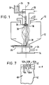
- the centrifugal spinning apparatus 10 (see Figure 1) has a housing 12 mounted on a base 14 and in which is mounted, for rotation on a vertical axis 16 by a drive mechanism (not shown), a cup-shaped spinning member 18.
- the upper end of the housing 12 has plenum arrangements 20, 22 through which primary and secondary air or other gases is fed, respectively, the air or other gases being at ambient temperature or, alternatively, being cooled or heated as required for a particular application by coolers and heaters (not shown), respectively.
- the lower end of the housing 12 has an exhaust duct 24 and a conveyor 26 for removing fibrous product 28 from the housing 12.
- a feed hopper 30, which includes a suitable feed mechanism such as a screw conveyor (not shown), is located to feed material to the member 18 via a feed supply tube 32 mounted concentrically with the axis 16 in the plenum 20, the tube 32 having an exit in the spinning member 18 adjacent the closed end of the member 18.
- the hopper 30 contains particulate or granular polymeric material 34, for example.
- the spinning member 18 has heater means such as an induction coil 36 connected to a suitable power supply and control means (not shown) and is provided with an insert member 38 to minimise turbulent gas flow within the apparatus 10 and within the member 18.
- the spinning member 18 is a cup-shaped member having a planar base 40 and a cylindrical wall 42 depending from the base 40.
- the base 40 of the member 18 has a central aperture 44 through which a feed supply pipe extends and fixing apertures 46 by which the member 18 is mounted on the drive means for rotation on the axis 16.
- the interior surface 48 of the wall 42 of the member 18 is smooth over a region extending from the base 40 to the bottom edge 50 of the member 18.
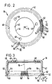
- Grooves 52 extend across the edge 50 from the interior surface 48 of the member 18 to the external periphery of the member 18.
- the centre lines or bases 54 and the peaks 56 of the grooves 52 lie in diametral planes.
- the grooves 52 terminate in spinning points 58 defined by V-shaped formations 60 on the external periphery of the member 18.
- the formations 60 lie in a common plane parallel to the base 40 of the member 18.
- a spinning member 18 of depth 70mm and diameter 100mm will have 120 or 180 spinning points.
- Guide fins 64 which lie in diametral planes, are intercalated between the grooves 52 and are located on the lower region of the interior surface 48 of the member 18.
- the member is spun at a desired rate and either a solution of material, or particles or granules of material, to be spun is fed to the member 18 to an annular feed passage defined between the base 40 of the member 18 and an adjacent surface of the insert member 36.
- the material is forced to the periphery of base 40 by centrifugal force and down the interior surface 48 of the member 18.
- the solution, or the material as it becomes molten, under the influence of centrifugal force forms a substantially uniform film on the interior surface 48 of the member 18.
- the film of solution, or melt reaches the fins 64, it is split into substantially equal streams which are then guided to the mouths of the grooves 52.
- the solution, or melt then flows along the grooves 52 to the spinning points 58 from which it is discharged as discrete filaments.
- the filaments either remain as filaments, whether continuous or discontinuous, the solvent being removed by evaporation, or the melt being cooled, or breaking up into discrete droplets to give a particulate or powder product form.
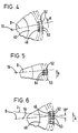
- the grooves 52 are asymmetrical, the bases of the grooves 52 and the trailing faces 53, relative to bowl rotation (indicated by arrow "A"), of the grooves 52 lie in diametral planes "D".
- the leading faces of the grooves 52 are at an angle of 30° to the trailing faces 53. Because the trailing faces 53 of the grooves 52 lie in diametral planes "D", the solution or melt has a greater tendency to flow along the grooves 52 to the spinning points 58 rather than to flow over the peaks of the grooves to an adjacent groove.
- the trailing faces 53 of the grooves 52 lie in planes which intersect the diametral planes "D" along the bases of the grooves 52. Those planes are at angles of 10°, in the direction of rotation of the arrow "A”, to the planes "D".
- FIG. 5 A further modification is shown in Figure 5.
- the fins 64 lie in the same planes as the trailing faces 53 of the grooves 52. The inclining of the fins 64 in that manner results in a smoother transfer of material from the surface 48 into the grooves 52.
- the grooves 52 are the same as the grooves 52 shown in Figure 4 except that trailing faces 53 of the grooves 52 lie in planes "I" which intersect diametral planes "D” at angles of 10° and along lines parallel to the axis 16. Owing to the circumferential component added to the radial component experienced by the filaments being discharged from the spinning points 58, the filaments exhibit greater stability and less tendency to shear away from the spinning points. Additionally, the filaments have a greater tendency to discharge from the actual points of the V-shaped formations 60 rather than from the trailing edge of the formations 60.
- two of the grooves 52A are filled in.
- an enlarged guide fin 64A Associated with each of the grooves 52A is an enlarged guide fin 64A.
- the fins 64A feed an amount of material to the groove 52B which would normally be distributed between the three grooves.
- the greater quantity of material flowing from the groove 52B results in a product form having a size distribution shifted away from the size distribution resulting from spinning the material from the grooves 52 thus giving bimodal distribution of product size.
- grooves 52A and 52B can be provided around the periphery of the spinning member 18 and that the number of grooves involved may differ, eg 2 or 4 etc. Furthermore, it will be apparent that such techniques can be readily adopted to give other distributions, eg trimodal.
- the apparatus 10 shown in Figure 1 is illustrative only and is not intended to be limitive. It will be apparent that the apparatus can take any convenient form depending upon the application, eg fibre spinning, spray drying etc, for which it is intended.
Landscapes
- Engineering & Computer Science (AREA)
- Mechanical Engineering (AREA)
- Textile Engineering (AREA)
- Spinning Methods And Devices For Manufacturing Artificial Fibers (AREA)
- Centrifugal Separators (AREA)
- Polysaccharides And Polysaccharide Derivatives (AREA)
- Crushing And Pulverization Processes (AREA)
Claims (11)
- Zentrifugalspinnvorrichtung, mit einem ringförmigen Spinnteil (18), das zur Rotation um eine Achse (16) konzentrisch dazu angebracht ist, einer Antriebseinrichtung für die Rotation des Teiles und einer Materialzufuhreinrichtung mit einem Ausgang in das Teil, wobei das Teil eine Innenfläche (48) hat, die über einen Bereich glatt ist, der sich von einem Ende (50) des Teiles, von dem das Material flüssiger Form versponnen wird, in Richtung auf den Ausgang der Materialzufuhreinrichtung (44) axial erstreckt, wobei das Ende des Teiles eine Vielzahl von auf dessen Außenumfang gebildeten Spinnpunkten (58) und Rillen (52) hat, welche sich über das Ende der Innenfläche zu dessen Außenumfang erstrecken, so daß das Material flüssiger Form zu den Spinnpunkten (58) geführt wird.
- Vorrichtung nach Anspruch 1, in der das Teil (18) tassenförmig ist, und zur Rotation um die Achse an seinem geschlossenen Ende montiert ist.
- Vorrichtung nach Anspruch 1, in der das Teil (18) die Form einer ringförmigen Hülse hat, die nach beiden Seiten offen und zur Rotation um die Achse mit Hilfe von generell in der Mitte der Hülse angeordneten Einrichtungen angebracht ist.
- Vorrichtung nach einem beliebigen der vorstehenden Ansprüche, in der der glatte Bereich der Innenfläche (48) im wesentlichen zylindrisch ist.
- Vorrichtung nach einem beliebigen der vorstehenden Ansprüche, in der die Spinnpunkte (58) durch mit den äußeren Enden der Rillen (52) übereinstimmende V-förmige Ausbildungen (60) definiert sind.
- Vorrichtung nach Anspruch 5, in der die Rillen (52) und ihre jeweiligen V-förmigen Ausbildungen (60) symmetrisch sind, wobei die Symmetrieebenen der Rillen entweder mit gegenüberliegenden Ebenen oder mit Ebenen übereinstimmen, die gegenüberliegende Ebenen spitzwinklig dazu und entlang parallel zur Achse verlaufender Linien schneiden.
- Vorrichtung nach Anspruch 5, in der die Rillen (52) und ihre jeweiligen V-förmigen Ausbildungen (60) asymmetrisch sind, wobei der Grund jeder Rille im wesentlichen in einer gegenüberliegenden Ebene des Teiles oder in einer Ebene liegt, die eine gegenüberliegende Ebene spitzwinklig dazu und entlang einer parallel zur Achse verlaufenden Linie schneidet.
- Vorrichtung nach Anspruch 7, in der die bezüglich der Rotationsrichtung des Teiles nachfolgende Fläche (53) jeder Rille (52) entweder in der Ebene des Rillengrundes oder in einer Ebene liegt, welche die Ebene des Rillengrundes entlang dem Grund und in Rotationsrichtung des Teiles spitzwinklig schneidet.
- Vorrichtung nach einem beliebigen der vorstehenden Ansprüche, in der die Spinnpunkte (58) auf einem Achsenradius sind, welcher größer als der Radius der unmittelbar an die Spinnpunkte (58) angrenzende Außenfläche des Teiles ist.
- Vorrichtung nach einem beliebigen der vorstehenden Ansprüche, in der das Ende (50) des Teiles, von dem das Material versponnen wird, abgeschrägt ist, wodurch das Ende ausgehend von der Innenfläche des Teiles in Richtung auf die Außenumfang des Teiles (50) nach außen auseinanderläuft.
- Vorrichtung nach einem beliebigen der vorstehenden Ansprüche, in der Führungsteile (64) auf der Innenfläche des Spinnteiles (18) bei Stellen angebracht sind, die zwischen den Öffnungen der Rillen (52) gelagert sind, wobei die Führungsteile (64) derart lang sind, daß der sich im Betrieb im glatten Bereich der Innenfläche des Spinnteiles (18) einstellende Materialfilm flüssiger Form durch die Führungsteile in getrennte Ströme aufgerissen oder geteilt wird, bevor er die Rillen (52) erreicht.
Applications Claiming Priority (2)
| Application Number | Priority Date | Filing Date | Title |
|---|---|---|---|
| GB9017157 | 1990-08-03 | ||
| GB909017157A GB9017157D0 (en) | 1990-08-03 | 1990-08-03 | Centrifugal spinning |
Publications (3)
| Publication Number | Publication Date |
|---|---|
| EP0469743A2 EP0469743A2 (de) | 1992-02-05 |
| EP0469743A3 EP0469743A3 (en) | 1992-04-29 |
| EP0469743B1 true EP0469743B1 (de) | 1994-09-28 |
Family
ID=10680196
Family Applications (1)
| Application Number | Title | Priority Date | Filing Date |
|---|---|---|---|
| EP91306450A Expired - Lifetime EP0469743B1 (de) | 1990-08-03 | 1991-07-16 | Vorrichtung zum Zentrifugalspinnen |
Country Status (10)
| Country | Link |
|---|---|
| US (1) | US5460498A (de) |
| EP (1) | EP0469743B1 (de) |
| JP (1) | JP3309089B2 (de) |
| AT (1) | ATE112182T1 (de) |
| DE (1) | DE69104303T2 (de) |
| DK (1) | DK0469743T3 (de) |
| ES (1) | ES2060305T3 (de) |
| FI (1) | FI913708A (de) |
| GB (1) | GB9017157D0 (de) |
| NO (1) | NO913016L (de) |
Families Citing this family (23)
| Publication number | Priority date | Publication date | Assignee | Title |
|---|---|---|---|---|
| US5743157A (en) * | 1996-07-31 | 1998-04-28 | Owens-Corning Fiberglas Technology, Inc. | Method for making a strengthened spinner having integrally formed ribs |
| US6284164B1 (en) | 1997-04-18 | 2001-09-04 | Gold Medal Products Company | Cotton candy machine |
| US5928550A (en) * | 1997-04-18 | 1999-07-27 | Gold Medal Products Co. | Popcorn popper with induction heating |
| GB9927950D0 (en) * | 1999-11-27 | 2000-01-26 | Knight David P | Apparatus and method for forming materials |
| US6585504B2 (en) | 2000-11-30 | 2003-07-01 | Gold Medal Products Company, Inc. | Cotton candy apparatus utilizing spinner head with film heater |
| US6752071B1 (en) | 2002-02-15 | 2004-06-22 | Gold Medal Products Company | Thick film heater for a popcorn popper |
| US6793151B2 (en) | 2002-09-18 | 2004-09-21 | R&J Inventions, Llc | Apparatus and method for centrifugal material deposition and products thereof |
| US20050238774A1 (en) * | 2004-04-22 | 2005-10-27 | Gold Medal Products Co. | Cotton candy machine |
| US20060147357A1 (en) * | 2004-12-31 | 2006-07-06 | Nextgen Chemical Processes Inc. | Thin film tube reactor |
| US20070287624A1 (en) * | 2006-06-13 | 2007-12-13 | Jon Frederick Bauer | Method for preparing glass |
| CA2703958A1 (en) * | 2007-10-23 | 2009-04-30 | Ppg Industries Ohio, Inc. | Fiber formation by electrical-mechanical spinning |
| CA2718922A1 (en) * | 2008-03-17 | 2009-09-24 | The Board Of Regents Of The University Of Texas System | Methods and apparatuses for making superfine fibers |
| JP2010180499A (ja) * | 2009-02-04 | 2010-08-19 | Panasonic Corp | ナノファイバ製造装置、ナノファイバ製造方法 |
| US9217210B2 (en) | 2009-03-24 | 2015-12-22 | North Carolina State University | Process of making composite inorganic/polymer nanofibers |
| US9217211B2 (en) | 2009-03-24 | 2015-12-22 | North Carolina State University | Method for fabricating nanofibers |
| US8551378B2 (en) * | 2009-03-24 | 2013-10-08 | North Carolina State University | Nanospinning of polymer fibers from sheared solutions |
| WO2012109215A2 (en) | 2011-02-07 | 2012-08-16 | Fiberio Technology Corporation | Apparatuses and methods for the production of microfibers and nanofibers |
| KR101503764B1 (ko) * | 2013-07-04 | 2015-03-18 | 주식회사 유성텔레콤 | 원심방사장치 |
| KR101503765B1 (ko) * | 2013-07-04 | 2015-03-19 | 주식회사 유성텔레콤 | 원심방사장치 |
| EP3413936A4 (de) | 2016-02-12 | 2019-11-20 | Tricol Biomedical, Inc. | Systeme aus superfeiner chitosanfaser |
| US11408096B2 (en) | 2017-09-08 | 2022-08-09 | The Board Of Regents Of The University Of Texas System | Method of producing mechanoluminescent fibers |
| WO2019218981A1 (zh) * | 2018-05-16 | 2019-11-21 | 苏州极目机器人科技有限公司 | 一种离心雾化结构及具有该离心雾化结构的喷洒装置、离心雾化装置、驱动装置及双驱动喷洒装置 |
| US11427937B2 (en) | 2019-02-20 | 2022-08-30 | The Board Of Regents Of The University Of Texas System | Handheld/portable apparatus for the production of microfibers, submicron fibers and nanofibers |
Family Cites Families (13)
| Publication number | Priority date | Publication date | Assignee | Title |
|---|---|---|---|---|
| NL296626A (de) * | ||||
| AU517923B2 (en) * | 1977-02-07 | 1981-09-03 | Ransburg Japan Ltd. | Rotary paint atomizing device |
| US4458844A (en) * | 1977-02-07 | 1984-07-10 | Ransburg Japan Ltd. | Improved rotary paint atomizing device |
| GB1573116A (en) * | 1977-03-11 | 1980-08-13 | Ici Ltd | Production of formaldehyde resin fibres by centrifugal spining |
| NZ187979A (en) * | 1977-07-29 | 1982-05-31 | Ici Ltd | Centrifugal spinning of fibres from liquid |
| NZ189726A (en) * | 1978-02-21 | 1981-05-29 | Ici Ltd | Chemical process on surface of rotating body |
| FR2432339A1 (fr) * | 1978-08-02 | 1980-02-29 | Bals Edward | Atomiseurs rotatifs |
| GB2026904B (en) * | 1978-08-02 | 1982-06-30 | Bals Edward Julius | Rotary atomiser |
| NO152016C (no) * | 1979-04-09 | 1985-07-17 | Ici Ltd | Sentrifugalspinnekopp |
| GB8424950D0 (en) * | 1984-10-03 | 1984-11-07 | Ici Plc | Non-woven fibrous materials |
| JPS62132725A (ja) * | 1985-12-04 | 1987-06-16 | Toyo Soda Mfg Co Ltd | 水素イオン交換型脱アルミニウムモルデナイトの製造方法 |
| US4919333A (en) * | 1986-06-26 | 1990-04-24 | The Devilbiss Company | Rotary paint atomizing device |
| JPS63229163A (ja) * | 1987-03-19 | 1988-09-26 | Toyota Motor Corp | 回転霧化静電塗装装置の噴霧頭 |
-
1990
- 1990-08-03 GB GB909017157A patent/GB9017157D0/en active Pending
-
1991
- 1991-07-16 AT AT91306450T patent/ATE112182T1/de not_active IP Right Cessation
- 1991-07-16 EP EP91306450A patent/EP0469743B1/de not_active Expired - Lifetime
- 1991-07-16 ES ES91306450T patent/ES2060305T3/es not_active Expired - Lifetime
- 1991-07-16 DE DE69104303T patent/DE69104303T2/de not_active Expired - Fee Related
- 1991-07-16 DK DK91306450.7T patent/DK0469743T3/da active
- 1991-08-01 JP JP19298891A patent/JP3309089B2/ja not_active Expired - Fee Related
- 1991-08-02 NO NO91913016A patent/NO913016L/no unknown
- 1991-08-02 FI FI913708A patent/FI913708A/fi not_active Application Discontinuation
-
1994
- 1994-06-29 US US08/268,653 patent/US5460498A/en not_active Expired - Fee Related
Also Published As
| Publication number | Publication date |
|---|---|
| ATE112182T1 (de) | 1994-10-15 |
| NO913016L (no) | 1992-02-04 |
| EP0469743A2 (de) | 1992-02-05 |
| JP3309089B2 (ja) | 2002-07-29 |
| DE69104303T2 (de) | 1995-03-09 |
| GB9017157D0 (en) | 1990-09-19 |
| EP0469743A3 (en) | 1992-04-29 |
| ES2060305T3 (es) | 1994-11-16 |
| JPH04240203A (ja) | 1992-08-27 |
| FI913708A (fi) | 1992-02-04 |
| FI913708A0 (fi) | 1991-08-02 |
| NO913016D0 (no) | 1991-08-02 |
| DE69104303D1 (de) | 1994-11-03 |
| DK0469743T3 (da) | 1995-04-24 |
| US5460498A (en) | 1995-10-24 |
Similar Documents
| Publication | Publication Date | Title |
|---|---|---|
| EP0469743B1 (de) | Vorrichtung zum Zentrifugalspinnen | |
| US4256677A (en) | Apparatus and method for making small spheres | |
| US5232638A (en) | Apparatus and method for introducing additives to fibrous products | |
| US4421412A (en) | Process and apparatus for processing plastic and polymeric materials | |
| US5279708A (en) | Spray drying process with spinning atomizer | |
| US4288397A (en) | Spinning process and apparatus | |
| US3831907A (en) | Continuous flow mixing apparatus | |
| US3040377A (en) | Method and apparatus for forming continuous filaments | |
| US4967688A (en) | Powder processing apparatus | |
| US3177058A (en) | Apparatus for processing heatsoftenable materials | |
| US5939120A (en) | Externally heated material processing apparatus and method | |
| EP0918891B1 (de) | Verfahren zur herstellung von organischen fasern | |
| US4772255A (en) | Method and apparatus for sizing grains smaller than 300μ | |
| JP4993154B2 (ja) | 回転ディスク上に均一厚さの液体又は溶融体の密着層を形成する方法及び装置 | |
| US4376084A (en) | Process for the production of heterogeneous articles | |
| JPS6122044B2 (de) | ||
| JP2022528933A (ja) | 粒子状材料の冷却装置 | |
| CN1382843A (zh) | 制备合成纤维材料的装置 | |
| CA1106117A (en) | Spinning fibres | |
| JPH0554376B2 (de) | ||
| RU2160332C1 (ru) | Установка для получения волокнистого материала из утиля и отходов термопластов | |
| RU2120380C1 (ru) | Червячно-дисковый экструдер | |
| JPH0569050B2 (de) | ||
| SU1151291A1 (ru) | Гранул тор расплавов | |
| JPH0352858B2 (de) |
Legal Events
| Date | Code | Title | Description |
|---|---|---|---|
| PUAI | Public reference made under article 153(3) epc to a published international application that has entered the european phase |
Free format text: ORIGINAL CODE: 0009012 |
|
| AK | Designated contracting states |
Kind code of ref document: A2 Designated state(s): AT BE CH DE DK ES FR GB GR IT LI LU NL SE |
|
| PUAL | Search report despatched |
Free format text: ORIGINAL CODE: 0009013 |
|
| AK | Designated contracting states |
Kind code of ref document: A3 Designated state(s): AT BE CH DE DK ES FR GB GR IT LI LU NL SE |
|
| 17P | Request for examination filed |
Effective date: 19920702 |
|
| 17Q | First examination report despatched |
Effective date: 19930305 |
|
| GRAA | (expected) grant |
Free format text: ORIGINAL CODE: 0009210 |
|
| AK | Designated contracting states |
Kind code of ref document: B1 Designated state(s): AT BE CH DE DK ES FR GB GR IT LI LU NL SE |
|
| ITF | It: translation for a ep patent filed |
Owner name: BARZANO' E ZANARDO MILANO S.P.A. |
|
| REF | Corresponds to: |
Ref document number: 112182 Country of ref document: AT Date of ref document: 19941015 Kind code of ref document: T |
|
| REF | Corresponds to: |
Ref document number: 69104303 Country of ref document: DE Date of ref document: 19941103 |
|
| REG | Reference to a national code |
Ref country code: GR Ref legal event code: FG4A Free format text: 3013456 |
|
| ET | Fr: translation filed | ||
| EAL | Se: european patent in force in sweden |
Ref document number: 91306450.7 |
|
| REG | Reference to a national code |
Ref country code: DK Ref legal event code: T3 |
|
| PLBE | No opposition filed within time limit |
Free format text: ORIGINAL CODE: 0009261 |
|
| STAA | Information on the status of an ep patent application or granted ep patent |
Free format text: STATUS: NO OPPOSITION FILED WITHIN TIME LIMIT |
|
| REG | Reference to a national code |
Ref country code: GB Ref legal event code: 732E |
|
| 26N | No opposition filed | ||
| REG | Reference to a national code |
Ref country code: CH Ref legal event code: PUE Owner name: IMPERIAL CHEMICAL INDUSTRIES PLC TRANSFER- ZENECA Ref country code: CH Ref legal event code: NV Representative=s name: BOVARD AG PATENTANWAELTE |
|
| NLS | Nl: assignments of ep-patents |
Owner name: ZENECA LIMITED |
|
| REG | Reference to a national code |
Ref country code: ES Ref legal event code: PC2A Owner name: ZENECA LIMITED |
|
| REG | Reference to a national code |
Ref country code: FR Ref legal event code: TP |
|
| REG | Reference to a national code |
Ref country code: GB Ref legal event code: 732E |
|
| REG | Reference to a national code |
Ref country code: CH Ref legal event code: PFA Free format text: ZENECA LIMITED TRANSFER- SYNGENTA LIMITED Ref country code: CH Ref legal event code: PUE Owner name: SYNGENTA LIMITED TRANSFER- AVECIA LIMITED |
|
| BECA | Be: change of holder's address |
Free format text: 20010822 *AVECIA LTD:HEXAGON HOUSE, BLACKLEY MANCHESTER M9 8ZS |
|
| BECH | Be: change of holder |
Free format text: 20010822 *AVECIA LTD |
|
| REG | Reference to a national code |
Ref country code: GB Ref legal event code: IF02 |
|
| NLS | Nl: assignments of ep-patents |
Owner name: AVECIA LIMITED |
|
| NLT1 | Nl: modifications of names registered in virtue of documents presented to the patent office pursuant to art. 16 a, paragraph 1 |
Owner name: SYNGENTA LIMITED |
|
| REG | Reference to a national code |
Ref country code: FR Ref legal event code: TP |
|
| REG | Reference to a national code |
Ref country code: CH Ref legal event code: NV Representative=s name: BOVARD AG PATENTANWAELTE |
|
| PGFP | Annual fee paid to national office [announced via postgrant information from national office to epo] |
Ref country code: GR Payment date: 20050613 Year of fee payment: 15 |
|
| PGFP | Annual fee paid to national office [announced via postgrant information from national office to epo] |
Ref country code: AT Payment date: 20050622 Year of fee payment: 15 |
|
| PGFP | Annual fee paid to national office [announced via postgrant information from national office to epo] |
Ref country code: NL Payment date: 20050703 Year of fee payment: 15 |
|
| PGFP | Annual fee paid to national office [announced via postgrant information from national office to epo] |
Ref country code: SE Payment date: 20050706 Year of fee payment: 15 |
|
| PGFP | Annual fee paid to national office [announced via postgrant information from national office to epo] |
Ref country code: FR Payment date: 20050708 Year of fee payment: 15 |
|
| PGFP | Annual fee paid to national office [announced via postgrant information from national office to epo] |
Ref country code: CH Payment date: 20050713 Year of fee payment: 15 Ref country code: GB Payment date: 20050713 Year of fee payment: 15 |
|
| PGFP | Annual fee paid to national office [announced via postgrant information from national office to epo] |
Ref country code: DE Payment date: 20050714 Year of fee payment: 15 |
|
| PGFP | Annual fee paid to national office [announced via postgrant information from national office to epo] |
Ref country code: DK Payment date: 20050715 Year of fee payment: 15 |
|
| PGFP | Annual fee paid to national office [announced via postgrant information from national office to epo] |
Ref country code: LU Payment date: 20050718 Year of fee payment: 15 |
|
| PGFP | Annual fee paid to national office [announced via postgrant information from national office to epo] |
Ref country code: ES Payment date: 20050818 Year of fee payment: 15 |
|
| PGFP | Annual fee paid to national office [announced via postgrant information from national office to epo] |
Ref country code: BE Payment date: 20050914 Year of fee payment: 15 |
|
| PG25 | Lapsed in a contracting state [announced via postgrant information from national office to epo] |
Ref country code: AT Free format text: LAPSE BECAUSE OF NON-PAYMENT OF DUE FEES Effective date: 20060716 Ref country code: GB Free format text: LAPSE BECAUSE OF NON-PAYMENT OF DUE FEES Effective date: 20060716 |
|
| PG25 | Lapsed in a contracting state [announced via postgrant information from national office to epo] |
Ref country code: SE Free format text: LAPSE BECAUSE OF NON-PAYMENT OF DUE FEES Effective date: 20060717 |
|
| PG25 | Lapsed in a contracting state [announced via postgrant information from national office to epo] |
Ref country code: CH Free format text: LAPSE BECAUSE OF NON-PAYMENT OF DUE FEES Effective date: 20060731 Ref country code: DK Free format text: LAPSE BECAUSE OF NON-PAYMENT OF DUE FEES Effective date: 20060731 Ref country code: LI Free format text: LAPSE BECAUSE OF NON-PAYMENT OF DUE FEES Effective date: 20060731 Ref country code: BE Free format text: LAPSE BECAUSE OF NON-PAYMENT OF DUE FEES Effective date: 20060731 |
|
| PGFP | Annual fee paid to national office [announced via postgrant information from national office to epo] |
Ref country code: IT Payment date: 20060731 Year of fee payment: 16 |
|
| PG25 | Lapsed in a contracting state [announced via postgrant information from national office to epo] |
Ref country code: NL Free format text: LAPSE BECAUSE OF NON-PAYMENT OF DUE FEES Effective date: 20070201 Ref country code: DE Free format text: LAPSE BECAUSE OF NON-PAYMENT OF DUE FEES Effective date: 20070201 |
|
| REG | Reference to a national code |
Ref country code: DK Ref legal event code: EBP |
|
| REG | Reference to a national code |
Ref country code: CH Ref legal event code: PL |
|
| EUG | Se: european patent has lapsed | ||
| GBPC | Gb: european patent ceased through non-payment of renewal fee |
Effective date: 20060716 |
|
| NLV4 | Nl: lapsed or anulled due to non-payment of the annual fee |
Effective date: 20070201 |
|
| REG | Reference to a national code |
Ref country code: FR Ref legal event code: ST Effective date: 20070330 |
|
| REG | Reference to a national code |
Ref country code: ES Ref legal event code: FD2A Effective date: 20060717 |
|
| BERE | Be: lapsed |
Owner name: *AVECIA LTD Effective date: 20060731 |
|
| PG25 | Lapsed in a contracting state [announced via postgrant information from national office to epo] |
Ref country code: ES Free format text: LAPSE BECAUSE OF NON-PAYMENT OF DUE FEES Effective date: 20060717 |
|
| PG25 | Lapsed in a contracting state [announced via postgrant information from national office to epo] |
Ref country code: FR Free format text: LAPSE BECAUSE OF NON-PAYMENT OF DUE FEES Effective date: 20060731 |
|
| PG25 | Lapsed in a contracting state [announced via postgrant information from national office to epo] |
Ref country code: LU Free format text: LAPSE BECAUSE OF NON-PAYMENT OF DUE FEES Effective date: 20060716 |
|
| PG25 | Lapsed in a contracting state [announced via postgrant information from national office to epo] |
Ref country code: GR Free format text: LAPSE BECAUSE OF NON-PAYMENT OF DUE FEES Effective date: 20070202 |
|
| PG25 | Lapsed in a contracting state [announced via postgrant information from national office to epo] |
Ref country code: IT Free format text: LAPSE BECAUSE OF NON-PAYMENT OF DUE FEES Effective date: 20070716 |