EP0469644A2 - Zeltboden - Google Patents
Zeltboden Download PDFInfo
- Publication number
- EP0469644A2 EP0469644A2 EP91118204A EP91118204A EP0469644A2 EP 0469644 A2 EP0469644 A2 EP 0469644A2 EP 91118204 A EP91118204 A EP 91118204A EP 91118204 A EP91118204 A EP 91118204A EP 0469644 A2 EP0469644 A2 EP 0469644A2
- Authority
- EP
- European Patent Office
- Prior art keywords
- floor
- support
- lateral beams
- support leg
- lateral
- Prior art date
- Legal status (The legal status is an assumption and is not a legal conclusion. Google has not performed a legal analysis and makes no representation as to the accuracy of the status listed.)
- Withdrawn
Links
Images


Classifications
-
- E—FIXED CONSTRUCTIONS
- E04—BUILDING
- E04H—BUILDINGS OR LIKE STRUCTURES FOR PARTICULAR PURPOSES; SWIMMING OR SPLASH BATHS OR POOLS; MASTS; FENCING; TENTS OR CANOPIES, IN GENERAL
- E04H15/00—Tents or canopies, in general
- E04H15/32—Parts, components, construction details, accessories, interior equipment, specially adapted for tents, e.g. guy-line equipment, skirts, thresholds
- E04H15/56—Floors
-
- B—PERFORMING OPERATIONS; TRANSPORTING
- B66—HOISTING; LIFTING; HAULING
- B66F—HOISTING, LIFTING, HAULING OR PUSHING, NOT OTHERWISE PROVIDED FOR, e.g. DEVICES WHICH APPLY A LIFTING OR PUSHING FORCE DIRECTLY TO THE SURFACE OF A LOAD
- B66F3/00—Devices, e.g. jacks, adapted for uninterrupted lifting of loads
- B66F3/08—Devices, e.g. jacks, adapted for uninterrupted lifting of loads screw operated
Definitions
- This invention concerns a floor, particularly in connection with adjustable legs or jacks for platforms, for instance floors in tents used together with caravans in order to increase the available protected area.
- the ground under the floor is mostly not prepared for the floor and the floor is necessary to enable the use of the tent in bad weather since the ground might become muddy and slippery.
- This need of a floor under caravan tents has been solved by using used wood in different shapes, for instance from loading pallets.
- the different legs of the floor may sink differently with time, resulting in an uneven surface of the floor and a corresponding time consuming work to regain the even surface.
- An uneven floor is not only aesthetically unpleasant but may be uncomfortable and dangerous.
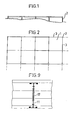
- FIG. 1 shows a lateral projection of a floor in accordance with the invention
- Fig 2 the same floor as seen from above
- Figs 3 and 4 show a tent floor module
- Fig 7 a detail of how the floor plane is built
- Fig 8 how the tent floor may be attached to the tent floor
- Fig 9 a crossectional profile of one of the support beams included in the tent floor
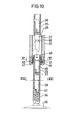
- Fig 10 a support leg of a tent floor in accordance with the invention
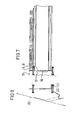
- Fig 11 the same support leg as in Fig 10 but with means for the operation
- Fig 12 details of Figs 11, 13 and 14 of alternative embodiments of the support leg as far its locking is concerned
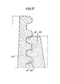
- Figs 15 and 16 a section of a reciprocal locking of the support leg parts and Fig 17 the thread profile.
- the tent floor according to the invention comprises a plurality of square modules 1 which are connected at their corner points by means of jacks or support legs 2 which will be described in greater detail below.
- the length of the support legs 2 is adjustable, which allows of adaptation to the ground.
- the lateral beams 3 framing the modules are restrictedly elastically attached to the support legs 2 the risk of no ground contact of a support leg, if this is carelessly adjusted with following great breaking risks is eliminated.
- the adjustment of the support legs is also simplified so that the floor becomes even and all the support legs absorb the pressure. If the structure should be non- elastic it would be difficult to decide if the force absorption at each support leg functions.
- By using the above-mentioned support leg it will, moreover, always be easy to adapt the level of the tent floor from the upper side to possible ground changes.
- each module 1 consists of platform battens 4. These are attached by means of Pop rivets 5 to steel bands 6 to a module sized platform.
- the platform is divided into two halves and in the joint between these the steel bands are connected by means of hinges 7. This enables a double folding of each module platform which may be advantageous at transport.
- the steel bands are folded at their ends to form a hook 8 which can grip a flange 9 on a lateral support beam 10. Mounting is carried out in the way shown in Fig 3 with a lightweight platform put down and flattened, the hooks 8 gripping the flanges 9.
- the profile of the lateral beams 19 is substantially I-shaped but their waist is extended upwards over the upper flanges corresponding to the thickness of the platform battens 4.
- the upper as well as the lower flange of the profile of the lateral beam 10 is hollow and as is shown in Figs 5 and 6 the legs 11, 12 of a U-shaped locking clamp 13 are pushed into the ends of the beam.
- the intermediate portion of the clamp 13 is somewhat arched towards the two legs 11, 12 and made of an elastic resilient material, preferably spring steel which may be e. g. stainless.
- the clamp is narrower between the legs and the intermediate portion of the clamp while the intermediate portion and the legs have the same width. It is therefore possible to push down the intermediate portion of the clamp in the way shown in Figs 5 and 6 into undercut slots 14 in the support legs 2. The clamp will then abut against a bottom section of the relative support leg.
- the locking clamp 13 is elastic there will firstly be no problem in mounting the beams 10 despite the fact that these will then sit without play. Secondly, the elasticity required in order that the floor should not be quite unresilient but can spring at loading on one hand, and settling in the ground, on the other hand, is obtained.
- the locking clamp 11 is attached to the beam 10 by means of rivets 15.
- each module is supported on the flanges 9 of the lateral beams 10 and another two support profiles 16 arranged perpendicularly to the battens 4 in the walking plane.
- These support profiles 16 are laterally arranged so that they divide the module length into three equal parts to achieve such an even absorption of forces as possible.
- These support profiles 16 have the appearance shown in Fig 9 i.e. an I-profile.
- the support profiles 16 engage slots 17 formed in the waists 10 of the lateral beams. It is especially apparent from Fig 7 how the support beams 16 are bevelled at their ends to engage the slots 17 of the lateral beams with a projection 18.
- the upper flange of the I-shaped beam 17 agress in respect of its position with the upper edges of the flanges 9 of the lateral beams 10.
- the support profiles 16 can be mounted very well after all the lateral beams have been mounted in position by hooking one end with the support profile a little inclined, after which the support profile is pressed laterally, the lateral beam springing away and the projection 18 of the support profile hooking into the slot 17 of the lateral beam.
- one of the steel bands 6 will be located between each support profile 16 and between these and the lateral beams 10, respectively.
- the steel bands do not function only to keep the battens 4 in the floor plane in their position but will also at a point load of a batten transfer the load to the adjacent battens via the steel band and the rivets with the result that the battens can be dimensioned to be more thin than should otherwise be the case with the relative graduation space, and in this way the weight of the tent floor can be maintained.
- Fig 7 it is shown how an ornamental ledge 19 has been hooked over the outer lateral beams of the tent floor and snapped into position.
- Fig 8 finally, it is shown how a clamp 20 engaging the lower lange 21 of the lateral beam 10 is arranged as an attachment of the very tent 22.
- each corner of the walking plane recesses for the adaptation to the support legs are arranged in the outer battens.
- a horizontal slot is arranged in the support legs on a level with the bottom of the battens and plate sections 23 are arranged as milled and riveted in the corners.
- the invention is of course not restricted to the embodiment shown above, but it is very well possible to make the modules triangular.
- the use of the floor need of course not be restricted to tent floors but it can certainly appear that the low weight and good adjustability of the floor can be used also on other occasions where permanent or temporary floors are to be achieved.
- a support leg in the form of a support leg housing 31 is shown, in the bottom of which a nut 32 is arranged nonrotatably.
- the threaded support leg 33 extends through this nut 32.
- the support leg consists of a lower portion 34 and an upper joint portion 35. Moreover, such a joint portion is shown freely above the very support leg.
- the support leg is terminated at its bottom portion by a foot member 36.
- Each support leg portion 34, 35 encludes a cylindrical, lightly tapered hole into which a corresponding projecting pin 37 on the portions 35 of the support leg portions 35 can be pushed. When the tapered pins 37 are pushed into the tapered holes 38 the shoulder portion 39 between pins and thread will abut against the upper end 40 of the support leg portion located below.
- a key handle is arranged in the bottom of each tapered recess 38 at the very front or down on the pin, respectively, which key handle is quite simply semi-circular in this case.
- this key handle 41 the threads agree for the consecutive support leg portions. In this way it will be possible to fill up with support leg portions 35 as desired when the support leg 33 is threaded downwards until it gets into contact with the ground and has lifted the support leg housing 31 to the desired height.
- the key or the crank 42 shown in Fig 11 is used for screwing down the support leg.
- This crank is also provided with a key handle corresponding to the key handle 41 furthest below.
- crank 42 is further provided with a stop means 44 which will abut the upper end of the support leg housing 31 because there is a need of a new support leg portion when the support leg has been screwed down enough. Therefore the key handle of the crank 42 and the support leg portion 43 will slide apart until the bevelling 43 makes the key 42 be pressed upwards.
- the crank is bevelled the driving ability is only lost in one direction while it is maintained in the other direction, and therefore the support leg can always be screwed up again if desired.
- the support leg 33 is slowly turning the nut 32, this has outer conical surfaces with the cone tip upwards in the bottom 45 of the support leg housing 31.
- the nut 32 is held on its place axially by a washer 46 which is held fast in turn by means of nuts 47 which also holds the bottom 45 of the support leg housing 31 to the support leg housing 31.
- a washer 46 which is held fast in turn by means of nuts 47 which also holds the bottom 45 of the support leg housing 31 to the support leg housing 31.
- the nut 32 has a sligth axial play and is for instance provided with a slot or is lightly elastic a compression of the nut 32 against the parts 34 or 35 of the support leg is obtained, as soon as there is a load on the support leg, which prevents thread wandering.
- the support legs can also be locked in the way shown in Fig 13 where the support leg 50 is directly threaded in the bottom 49 of a support leg housing 48.
- a threaded washer 51 is arranged beneath the bottom 49 with a slight axial play, which washer is also threaded onto the support leg 50.
- the axial play of the washer and its turning stop, respectively, are so arranged that the thread in the bottom and the wahser 51, respectively, agree at downward turning while at upward threading the washer must in a way not shown be retained in this position (e.g. by pushing down a rod or the like through a hole arranged in the housing) in order to prevent the washer from accompanying the turning of the support leg so much that the threads are wedged reciprocally.
- Fig 14 shows a further way of locking the support leg in a definite position.
- the bottom 53 of the support leg housing 52 is provided with a horizontal slot 54.
- a screw 50 is threaded which can be actuated from above and clamps the slot 24 together and locks the threading in this way.
- a device such as is exemplified in Figs 10, 15 and 16 can be used.
- Two recesses 57 and 58, respectively, are arranged straight in front of each other in the cylindrical upper portion of each support leg section.
- the recess 58 is relatively small while the recess 57 is relatively broad and a circlip 59 is arranged in these.
- the circlip has axially a height corresponding to abut the pitch as apparent from Fig 10.
- the spring ring 59 In unactuated state the spring ring 59 is in the position shown in Fig 16, i.e. it extends to the thread tops.
- the circlip 59 is pressed by the nut inwards in radial direction.
- the circlip will then expand in the portions being within the tapered recess of the support leg portion where, moreover, a recess is arranged to be able to absorb at least the width of the circlip so that it comes on a level with the cone surface at its lower edge.
- the circlip will then enter the position shown in Fig 15. In the position shown in Fig 15 the circlip 59 will release the groove 60 running all around on the support leg portion 35 and this can be removed out of the lower support leg portion.
- support leg portions can always be inserted and taken out of support leg portions located below when the circlip section 53 is in the nut 32.
- the internal groove running all around in the cylindrical portion of the support leg section 35 need not be undercut as the lower edge of the circlip 59 need only be pressed in to the level of the conical surface therein and consequently it is possible to manufacture the support leg pieces by die casting in e.g. aluminum.
- the axial play of the thread in the nut 32 are preferably a little greater than the turning play of the reciprocal key handles. After adjustment of the support leg this is upwardly sealed by a cover.
Applications Claiming Priority (4)
| Application Number | Priority Date | Filing Date | Title |
|---|---|---|---|
| SE8403393A SE455513B (sv) | 1984-06-26 | 1984-06-26 | Forteltsgolv |
| SE8403394 | 1984-06-26 | ||
| SE8403393 | 1984-06-26 | ||
| SE8403394A SE447927B (sv) | 1984-06-26 | 1984-06-26 | Gengskarv |
Related Parent Applications (2)
| Application Number | Title | Priority Date | Filing Date |
|---|---|---|---|
| EP85850218A Division EP0167509B1 (de) | 1984-06-26 | 1985-06-24 | Gewindeverstellvorrichtung |
| EP85850218.0 Division | 1985-06-24 |
Publications (2)
| Publication Number | Publication Date |
|---|---|
| EP0469644A2 true EP0469644A2 (de) | 1992-02-05 |
| EP0469644A3 EP0469644A3 (de) | 1992-03-11 |
Family
ID=26658749
Family Applications (2)
| Application Number | Title | Priority Date | Filing Date |
|---|---|---|---|
| EP19910118204 Withdrawn EP0469644A3 (de) | 1984-06-26 | 1985-06-24 | Zeltboden |
| EP85850218A Expired - Lifetime EP0167509B1 (de) | 1984-06-26 | 1985-06-24 | Gewindeverstellvorrichtung |
Family Applications After (1)
| Application Number | Title | Priority Date | Filing Date |
|---|---|---|---|
| EP85850218A Expired - Lifetime EP0167509B1 (de) | 1984-06-26 | 1985-06-24 | Gewindeverstellvorrichtung |
Country Status (3)
| Country | Link |
|---|---|
| EP (2) | EP0469644A3 (de) |
| AT (1) | ATE103882T1 (de) |
| DE (1) | DE3587789T2 (de) |
Cited By (3)
| Publication number | Priority date | Publication date | Assignee | Title |
|---|---|---|---|---|
| DE9204037U1 (de) * | 1992-03-26 | 1992-05-21 | Losberger Intertent Gmbh, 7100 Heilbronn, De | |
| DE19809733B4 (de) * | 1998-03-08 | 2007-01-18 | Röder Zelt- und Veranstaltungsservice GmbH | Unterbau eines Zeltes mit Ballastsicherung |
| BE1019129A3 (nl) * | 2009-12-28 | 2012-03-06 | Craeynest Lionel Eug Ne | Vloerconstructie. |
Families Citing this family (3)
| Publication number | Priority date | Publication date | Assignee | Title |
|---|---|---|---|---|
| US10508467B2 (en) * | 2015-08-19 | 2019-12-17 | biljax, inc. | Engineered floor and scaffold systems |
| US11280108B1 (en) * | 2019-02-05 | 2022-03-22 | Shawn Szepi | Water diverting ground platform |
| US11959300B2 (en) * | 2020-09-02 | 2024-04-16 | Bil-Jax, Inc. | Floor structure system and method of use |
Citations (3)
| Publication number | Priority date | Publication date | Assignee | Title |
|---|---|---|---|---|
| DE1974151U (de) * | 1967-08-17 | 1967-12-07 | Reinhold Traut | Zerlegbare campingbuehne. |
| DE7317699U (de) * | 1973-05-11 | 1973-09-20 | Haury H | Starrer boden im baukastenprinzip insbesondere fuer camping-zelte |
| DE2325202A1 (de) * | 1973-05-18 | 1974-12-05 | Hans Ott | Bausatz fuer einen laufboden fuer campingzelte |
Family Cites Families (3)
| Publication number | Priority date | Publication date | Assignee | Title |
|---|---|---|---|---|
| US1457825A (en) * | 1921-05-16 | 1923-06-05 | Paul J Devan | Screw jack |
| US2548844A (en) * | 1947-03-21 | 1951-04-10 | Summit Steel Products Inc | Adjustable post |
| FR2178736A1 (de) * | 1972-04-05 | 1973-11-16 | Draner Sarl |
-
1985
- 1985-06-24 DE DE3587789T patent/DE3587789T2/de not_active Expired - Fee Related
- 1985-06-24 AT AT85850218T patent/ATE103882T1/de not_active IP Right Cessation
- 1985-06-24 EP EP19910118204 patent/EP0469644A3/de not_active Withdrawn
- 1985-06-24 EP EP85850218A patent/EP0167509B1/de not_active Expired - Lifetime
Patent Citations (3)
| Publication number | Priority date | Publication date | Assignee | Title |
|---|---|---|---|---|
| DE1974151U (de) * | 1967-08-17 | 1967-12-07 | Reinhold Traut | Zerlegbare campingbuehne. |
| DE7317699U (de) * | 1973-05-11 | 1973-09-20 | Haury H | Starrer boden im baukastenprinzip insbesondere fuer camping-zelte |
| DE2325202A1 (de) * | 1973-05-18 | 1974-12-05 | Hans Ott | Bausatz fuer einen laufboden fuer campingzelte |
Cited By (4)
| Publication number | Priority date | Publication date | Assignee | Title |
|---|---|---|---|---|
| DE9204037U1 (de) * | 1992-03-26 | 1992-05-21 | Losberger Intertent Gmbh, 7100 Heilbronn, De | |
| DE4237635A1 (de) * | 1992-03-26 | 1993-09-30 | Losberger Intertent Gmbh | Bausatz zur Erstellung eines Fußbodens |
| DE19809733B4 (de) * | 1998-03-08 | 2007-01-18 | Röder Zelt- und Veranstaltungsservice GmbH | Unterbau eines Zeltes mit Ballastsicherung |
| BE1019129A3 (nl) * | 2009-12-28 | 2012-03-06 | Craeynest Lionel Eug Ne | Vloerconstructie. |
Also Published As
| Publication number | Publication date |
|---|---|
| ATE103882T1 (de) | 1994-04-15 |
| EP0167509A2 (de) | 1986-01-08 |
| DE3587789T2 (de) | 1994-10-27 |
| EP0167509B1 (de) | 1994-04-06 |
| EP0167509A3 (en) | 1989-11-08 |
| DE3587789D1 (de) | 1994-05-11 |
| EP0469644A3 (de) | 1992-03-11 |
Similar Documents
| Publication | Publication Date | Title |
|---|---|---|
| CA2769400C (en) | Support pedestal for supporting an elevated building surface | |
| US8898999B1 (en) | Restraint system for elevated surface tiles | |
| US5056750A (en) | Support column | |
| US8616519B2 (en) | Shoring post with supplemental beam support | |
| US6199489B1 (en) | Folding table | |
| US20190142160A1 (en) | Leveling foot | |
| US20110239550A1 (en) | Stability bracing of a support structure for elevating a building surface | |
| EP0469644A2 (de) | Zeltboden | |
| US5359827A (en) | Hollow fence post attachment fixture | |
| CA2587549A1 (en) | Support structure for elevated floor assembly | |
| EP0058042A1 (de) | Vorrichtung zur Befestigung eines Elementes am Stützrohr einer Stützkonstruktion | |
| EP1797255B1 (de) | Gerüstbrett mit lösbarer hakenanordnung | |
| US2753222A (en) | Scaffold and sawhorse bracket | |
| KR100905697B1 (ko) | 조립형 데크 연결구조 | |
| US4098198A (en) | Table with two braced legs | |
| KR100662301B1 (ko) | 가전제품용 레그 록너트 | |
| KR200372703Y1 (ko) | 개량형 하우스 골조구조 | |
| US4750309A (en) | Structural support bracket | |
| KR200250962Y1 (ko) | 알루미늄 프로파일용 고정너트 | |
| JP4124881B2 (ja) | 高さ調節床束のクイック・レベルロック機構。 | |
| CA2775453C (en) | Stability bracing of a support structure for elevating a building surface | |
| DE202009004916U1 (de) | Gerüst sowie Ausleger für ein solches | |
| DE4442747A1 (de) | Modulares Regalsystem | |
| KR200343583Y1 (ko) | 천정구조물의 클립 | |
| DE20012279U1 (de) | Möbeluntergestell |
Legal Events
| Date | Code | Title | Description |
|---|---|---|---|
| PUAI | Public reference made under article 153(3) epc to a published international application that has entered the european phase |
Free format text: ORIGINAL CODE: 0009012 |
|
| PUAL | Search report despatched |
Free format text: ORIGINAL CODE: 0009013 |
|
| AC | Divisional application: reference to earlier application |
Ref document number: 167509 Country of ref document: EP |
|
| AK | Designated contracting states |
Kind code of ref document: A2 Designated state(s): AT BE CH DE FR GB IT LI LU NL SE |
|
| AK | Designated contracting states |
Kind code of ref document: A3 Designated state(s): AT BE CH DE FR GB IT LI LU NL SE |
|
| K1C3 | Correction of patent application (complete document) published |
Effective date: 19920205 |
|
| 17P | Request for examination filed |
Effective date: 19920622 |
|
| RBV | Designated contracting states (corrected) |
Designated state(s): DE FR GB |
|
| 17Q | First examination report despatched |
Effective date: 19931216 |
|
| STAA | Information on the status of an ep patent application or granted ep patent |
Free format text: STATUS: THE APPLICATION IS DEEMED TO BE WITHDRAWN |
|
| 18D | Application deemed to be withdrawn |
Effective date: 19951212 |