EP0468945B1 - Clamping means and sleeper assembly - Google Patents
Clamping means and sleeper assembly Download PDFInfo
- Publication number
- EP0468945B1 EP0468945B1 EP91850184A EP91850184A EP0468945B1 EP 0468945 B1 EP0468945 B1 EP 0468945B1 EP 91850184 A EP91850184 A EP 91850184A EP 91850184 A EP91850184 A EP 91850184A EP 0468945 B1 EP0468945 B1 EP 0468945B1
- Authority
- EP
- European Patent Office
- Prior art keywords
- sleeper
- clamping means
- spring
- unit
- rail
- Prior art date
- Legal status (The legal status is an assumption and is not a legal conclusion. Google has not performed a legal analysis and makes no representation as to the accuracy of the status listed.)
- Expired - Lifetime
Links
- 241001669679 Eleotris Species 0.000 title claims abstract description 32
- 230000010355 oscillation Effects 0.000 claims description 4
- 230000001419 dependent effect Effects 0.000 description 1
- 230000000149 penetrating effect Effects 0.000 description 1
- 230000000284 resting effect Effects 0.000 description 1
- 238000010079 rubber tapping Methods 0.000 description 1
Images
Classifications
-
- E—FIXED CONSTRUCTIONS
- E01—CONSTRUCTION OF ROADS, RAILWAYS, OR BRIDGES
- E01B—PERMANENT WAY; PERMANENT-WAY TOOLS; MACHINES FOR MAKING RAILWAYS OF ALL KINDS
- E01B9/00—Fastening rails on sleepers, or the like
- E01B9/02—Fastening rails, tie-plates, or chairs directly on sleepers or foundations; Means therefor
- E01B9/28—Fastening on wooden or concrete sleepers or on masonry with clamp members
- E01B9/30—Fastening on wooden or concrete sleepers or on masonry with clamp members by resilient steel clips
Definitions
- the present invention relates to a clamping means and sleeper assembly according to the preamble of claim 1.
- a pivotable clamping means enables extremely simple attachment of a rail to a sleeper and requires only one tool which can turn the clamping means about its axis. Thus, apart from the actual turning tool, there are no loose parts whatsoever. If a rail is to be replaced the clamping means need only be turned from its contact position, thus making replacement extremely easy.
- a unit can be utilized on rails already laid, said unit being displaced along the rail, thereby turning the clamping means to abutment with the rail foot or turning it out of contact with the rail foot.
- the spring may consist of a helical spring or some other spring device like a rolled laminated spring standing on edge, cup springs, ring springs or Archimedes springs arranged about the axis of oscillation of the clamping means.
- the spring itself is so dimensioned that when the clamping means is in contact with the foot of the rail, a pressure is obtained which is sufficient to retain the rail in position when it is used for traffic and at fluctuations in temperature.
- the temperature in winter may be -50°C and in summer it may be over 40°C.
- the lower end of the spring may be extended so that it is in contact with the flange or tongue of the clamping means.
- the clamping means may cooperate with a snap device so that when the clamping means is in operating position, i.e. in contact with the foot of the rail the snap device will come into operation. In all other positions the snap device will be out of operation.
- the clamping means may be arranged on a plate secured on the upper side of a sleeper.
- the axis of oscillation of the clamping means may also be secured inside the sleeper itself, either by means of a tapping arrangement or by grouting. According to the latter alternative, the sleeper itself is made of concrete.
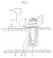
- Fig 1 shows a rail 1 with head 2, web 3 and foot 4.
- the foot rests on a sleeper 5.
- the sleeper is made of concrete and has a shaft 6 grouted into it, the shaft being provided with cavities 7.
- the function of the cavities is to fix the position of the shaft 6 in the sleeper when the concrete has solidified.
- the lower end of the shaft may be optionally desired provided the shaft 6 is permanently secured when the concrete has set.
- a unit 9 is applied about the shaft 6, suitably resting on a plate shown in Fig 4 and designated 15. Said plate 15 is suitably permanently joined to the shaft 6.
- the unit 9 is provided with an aperture enabling it to be pivoted about the shaft 6.
- the unit 9 is provided with a radially outwardly directed tongue or flange 10.
- a helical spring 11 is provided in the clamping means. One end of said spring 11 is abutting against the unit 9. The other end of the helical spring acts on a plate 12 riveted to the shaft 6 which limits its upward movement.
- Reference sign 13 designates the head of a screw or rivet.
- the lower end 14 of the spring is pulled out and is in contact with the tongue, as shown in Figures 2 and 3.
- the spring 11 is dimensioned so as to achieve a pressure on the tongue 10 that is sufficient to retain the rail when it is subjected to the stresses caused by traffic and also by temperature fluctuations.
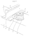
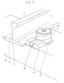
- Figures 2 and 3 show the clamping means in operation with its tongue in contact with the rail foot and with the tongue out of its retaining position.
- the actual unit 9 and sleeper 5 may be so designed that when the unit assumes the position shown in Fig 2, the snap device will come into operation thereby positioning the unit correctly to carry out its retaining function. It is clear from the drawings that the unit 9 can be turned to an unlimited extent about its axis 6.
- the unit 9 with parts 6-8 and 10-13 is normally in the form of a prefabricated unit and is therefore easy to apply on a sleeper. If a clamping means is damaged only the head of the screw or rivet need be ground off. Damaged parts can then easily be replaced and a new head welded on.
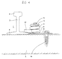
- Fig 4 shows a unit which functions in exactly the same manner as that illustrated in the previous figures but which differs in that the axis 6 is a tubular shaft secured to a plate 15 attached to the sleeper 5 by means of a screw joint 16.
- the shaft 6 may comprise a pipe with a screw running through it and penetrating into the sleeper 5 below, thereby securing the clamping means to the sleeper.
- a threaded sleeve can be grouted into the sleeper 5 if it is made of concrete.
- the unit may then be designed so that when it passes a unit 9 it either turns this to achieve contact with the rail foot or to disengage it from the rail foot.
Landscapes
- Engineering & Computer Science (AREA)
- Mechanical Engineering (AREA)
- Architecture (AREA)
- Civil Engineering (AREA)
- Structural Engineering (AREA)
- Railway Tracks (AREA)
- Bridges Or Land Bridges (AREA)
- Machines For Laying And Maintaining Railways (AREA)
- Slide Fasteners, Snap Fasteners, And Hook Fasteners (AREA)
- Traffic Control Systems (AREA)
Abstract
Description
- The present invention relates to a clamping means and sleeper assembly according to the preamble of
claim 1. - In the US-A-3 018 967 is disclosed such an assembly, the object of which is to facilitate attaching rails to a sleeper and also to facilitate the removal of a rail from a sleeper. According to the patent a clamping means is used having a tongue which is pivotably journalled on a sleeper in such a manner that the clamping means can be pivoted into contact against a rail foot and out of contact with said foot. The object of the present invention is to provide an assembly of improved design. This object is achieved by an assembly according to
claim 1. Further advantageous features are defined by the dependent claims. - The use of a pivotable clamping means enables extremely simple attachment of a rail to a sleeper and requires only one tool which can turn the clamping means about its axis. Thus, apart from the actual turning tool, there are no loose parts whatsoever. If a rail is to be replaced the clamping means need only be turned from its contact position, thus making replacement extremely easy.
- Instead of using a tool to turn the clamping means a unit can be utilized on rails already laid, said unit being displaced along the rail, thereby turning the clamping means to abutment with the rail foot or turning it out of contact with the rail foot.
- In the present invention, the spring may consist of a helical spring or some other spring device like a rolled laminated spring standing on edge, cup springs, ring springs or Archimedes springs arranged about the axis of oscillation of the clamping means. The spring itself is so dimensioned that when the clamping means is in contact with the foot of the rail, a pressure is obtained which is sufficient to retain the rail in position when it is used for traffic and at fluctuations in temperature. The temperature in winter may be -50°C and in summer it may be over 40°C.
- The lower end of the spring may be extended so that it is in contact with the flange or tongue of the clamping means.
- The clamping means may cooperate with a snap device so that when the clamping means is in operating position, i.e. in contact with the foot of the rail the snap device will come into operation. In all other positions the snap device will be out of operation.
- The clamping means may be arranged on a plate secured on the upper side of a sleeper.
- The axis of oscillation of the clamping means may also be secured inside the sleeper itself, either by means of a tapping arrangement or by grouting. According to the latter alternative, the sleeper itself is made of concrete.
- Further advantageous characteristics of the present invention are revealed in the appended claims.
- The invention will be described in more detail in connection with the accompanying four sheets of drawings in which
- Fig 1
- shows a rail on a sleeper and a clamping means anchored to the sleeper,
- Fig 2 and 3
- show the clamping means in two different positions, and
- Fig 4
- shows a different arrangement for securing the clamping means to a sleeper.
- Fig 1 shows a
rail 1 withhead 2,web 3 andfoot 4. The foot rests on asleeper 5. The sleeper is made of concrete and has ashaft 6 grouted into it, the shaft being provided withcavities 7. The function of the cavities is to fix the position of theshaft 6 in the sleeper when the concrete has solidified. The lower end of the shaft may be optionally desired provided theshaft 6 is permanently secured when the concrete has set. Aunit 9 is applied about theshaft 6, suitably resting on a plate shown in Fig 4 and designated 15. Saidplate 15 is suitably permanently joined to theshaft 6. Theunit 9 is provided with an aperture enabling it to be pivoted about theshaft 6. Theunit 9 is provided with a radially outwardly directed tongue orflange 10. When rotated about theshaft 6 the tongue of the clamping means can either be brought into contact with thefoot 4 of the rail or disengaged therefrom. Ahelical spring 11 is provided in the clamping means. One end of saidspring 11 is abutting against theunit 9. The other end of the helical spring acts on aplate 12 riveted to theshaft 6 which limits its upward movement.Reference sign 13 designates the head of a screw or rivet. Thelower end 14 of the spring is pulled out and is in contact with the tongue, as shown in Figures 2 and 3. Thespring 11 is dimensioned so as to achieve a pressure on thetongue 10 that is sufficient to retain the rail when it is subjected to the stresses caused by traffic and also by temperature fluctuations. - Figures 2 and 3 show the clamping means in operation with its tongue in contact with the rail foot and with the tongue out of its retaining position.
- The
actual unit 9 andsleeper 5 may be so designed that when the unit assumes the position shown in Fig 2, the snap device will come into operation thereby positioning the unit correctly to carry out its retaining function. It is clear from the drawings that theunit 9 can be turned to an unlimited extent about itsaxis 6. - The
unit 9 with parts 6-8 and 10-13 is normally in the form of a prefabricated unit and is therefore easy to apply on a sleeper. If a clamping means is damaged only the head of the screw or rivet need be ground off. Damaged parts can then easily be replaced and a new head welded on. - Fig 4 shows a unit which functions in exactly the same manner as that illustrated in the previous figures but which differs in that the
axis 6 is a tubular shaft secured to aplate 15 attached to thesleeper 5 by means of ascrew joint 16. Theshaft 6 may comprise a pipe with a screw running through it and penetrating into thesleeper 5 below, thereby securing the clamping means to the sleeper. A threaded sleeve can be grouted into thesleeper 5 if it is made of concrete. - As is clear from the above, no loose parts whatsoever are required to secure a
rail 1 to a sleeper. The only measure required is to turn theunit 9 into or out of abutment with therail foot 4. - It should be evident that it is possible to displace a unit along rails already laid. The unit may then be designed so that when it passes a
unit 9 it either turns this to achieve contact with the rail foot or to disengage it from the rail foot.
Claims (5)
- A clamping means and sleeper assembly comprising a clamping means for attaching a rail to a sleeper or crosstie (5) in a railway track, said clamping means comprising a unit (9) permanently secured to a cooperating sleeper and pivotably journalled about a shaft (6) located substantially perpendicular to the upper surface of said sleeper, said unit (9) being provided with an outwardly directed tongue or flange (10) which can be brought into and out of contact with the foot (4) of the rail to press said foot against the upper side of said sleeper, said tongue or flange being influenced by a spring force,
characterised in that said unit (9) is influenced by a spring (11), for instance a helical spring, a laminated spring, a cup spring, a ring spring or an Archimedes spring, arranged about said shaft (6), one end of the spring (11) abutting against the unit (9) and the other end abutting against a surface (12) at the upper end of the shaft (6). - A clamping means as claimed in claim 1,
characterised in that the spring force (11) is such that satisfactory clamping effect is obtained when the tongue (10) abuts the foot (4) and when the rail (1) is trafficated. - A clamping means as claimed in claim 1,
characterised in that one end of the shaft (6) forming the axis of oscillation of the unit (9) is grouted or bolted into the cooperating sleeper (5). - A clamping means as claimed in claim 3,
characterised in that one end of the said axis of oscillation (6) is secured to a plate (15) permanently applied on the sleeper (5) by means of a screw joint (16), for instance. - A clamping means as claimed in one or more of the preceding claims, characterised in that a snap device is arranged for the unit (9), said snap device coming into operation when the tongue (10) is in contact with the foot (4) of the rail.
Priority Applications (1)
| Application Number | Priority Date | Filing Date | Title |
|---|---|---|---|
| AT91850184T ATE101888T1 (en) | 1990-07-19 | 1991-07-04 | FASTENER WITH THRESHOLD. |
Applications Claiming Priority (2)
| Application Number | Priority Date | Filing Date | Title |
|---|---|---|---|
| SE9002462A SE509038C2 (en) | 1990-07-19 | 1990-07-19 | Procedure for attaching a rail to a screen and clamping device to enable the method |
| SE9002462 | 1990-07-19 |
Publications (2)
| Publication Number | Publication Date |
|---|---|
| EP0468945A1 EP0468945A1 (en) | 1992-01-29 |
| EP0468945B1 true EP0468945B1 (en) | 1994-02-23 |
Family
ID=20380024
Family Applications (1)
| Application Number | Title | Priority Date | Filing Date |
|---|---|---|---|
| EP91850184A Expired - Lifetime EP0468945B1 (en) | 1990-07-19 | 1991-07-04 | Clamping means and sleeper assembly |
Country Status (6)
| Country | Link |
|---|---|
| EP (1) | EP0468945B1 (en) |
| AT (1) | ATE101888T1 (en) |
| DE (1) | DE69101229T2 (en) |
| ES (1) | ES2049541T3 (en) |
| RU (1) | RU2052556C1 (en) |
| SE (1) | SE509038C2 (en) |
Cited By (2)
| Publication number | Priority date | Publication date | Assignee | Title |
|---|---|---|---|---|
| US6844142B2 (en) | 2002-09-09 | 2005-01-18 | Basf Drucksysteme Gmbh | Production of flexographic printing plates by thermal development |
| DE102005058444B3 (en) * | 2005-12-07 | 2007-04-26 | Db Netz Ag | Fastening means for rails onto sleepers or tracks has sprung clamp with curved pressure strap having clip straps brought with rail foot into pre-tensioned position when turned, clamp anchorage with guide means |
Families Citing this family (5)
| Publication number | Priority date | Publication date | Assignee | Title |
|---|---|---|---|---|
| EP0641408B1 (en) * | 1992-05-13 | 1997-12-29 | HARMS & HAFFKE GMBH & CO | System for securing rails on the sole plates of a railway track |
| RU2167233C2 (en) * | 1998-08-13 | 2001-05-20 | Архипов Валерьян Михайлович | Rail fastening |
| WO2005116339A1 (en) * | 2004-05-25 | 2005-12-08 | Obschestvo S Ogranichennoi Otvetstvennostiyu Sovmestnoe Rossysko-Amerikanskoe Predpriyatie'tehnologiya Xxi Veka' | Provisional rail fastening |
| DE102005058467A1 (en) * | 2005-12-07 | 2007-06-14 | Db Netz Ag | Fasteners for fastening railway tracks on sleepers or tracks |
| PT3346054T (en) | 2017-01-10 | 2022-01-19 | Schwihag Ag | Tension clamp and rail fastening system for fastening railway rails |
Family Cites Families (3)
| Publication number | Priority date | Publication date | Assignee | Title |
|---|---|---|---|---|
| US1562458A (en) * | 1925-06-25 | 1925-11-24 | Bethlehem Steel Corp | Metallic railway tie |
| US3018967A (en) * | 1953-03-12 | 1962-01-30 | Khalil Muhammad | Method and means for the installation of rail track |
| GB959113A (en) * | 1961-11-29 | 1964-05-27 | Toledo Woodhead Springs Ltd | Improvements in or relating to clipping devices for railway rails |
-
1990
- 1990-07-19 SE SE9002462A patent/SE509038C2/en not_active IP Right Cessation
-
1991
- 1991-07-04 ES ES91850184T patent/ES2049541T3/en not_active Expired - Lifetime
- 1991-07-04 AT AT91850184T patent/ATE101888T1/en active
- 1991-07-04 EP EP91850184A patent/EP0468945B1/en not_active Expired - Lifetime
- 1991-07-04 DE DE69101229T patent/DE69101229T2/en not_active Expired - Fee Related
- 1991-07-18 RU SU915001130A patent/RU2052556C1/en not_active IP Right Cessation
Cited By (2)
| Publication number | Priority date | Publication date | Assignee | Title |
|---|---|---|---|---|
| US6844142B2 (en) | 2002-09-09 | 2005-01-18 | Basf Drucksysteme Gmbh | Production of flexographic printing plates by thermal development |
| DE102005058444B3 (en) * | 2005-12-07 | 2007-04-26 | Db Netz Ag | Fastening means for rails onto sleepers or tracks has sprung clamp with curved pressure strap having clip straps brought with rail foot into pre-tensioned position when turned, clamp anchorage with guide means |
Also Published As
| Publication number | Publication date |
|---|---|
| SE509038C2 (en) | 1998-11-30 |
| DE69101229T2 (en) | 1994-06-01 |
| RU2052556C1 (en) | 1996-01-20 |
| DE69101229D1 (en) | 1994-03-31 |
| EP0468945A1 (en) | 1992-01-29 |
| ES2049541T3 (en) | 1994-04-16 |
| ATE101888T1 (en) | 1994-03-15 |
| SE9002462D0 (en) | 1990-07-19 |
| SE9002462L (en) | 1992-01-20 |
Similar Documents
| Publication | Publication Date | Title |
|---|---|---|
| US2750142A (en) | Fitting or coupling for bracket arm | |
| CA2096456A1 (en) | Method for constructing a railroad in concrete | |
| EP0468945A1 (en) | Clamping means and sleeper assembly | |
| JPH08511593A (en) | Holding device for face plate | |
| US5038704A (en) | Stowable temporary signaling device for rail systems | |
| CN201089872Y (en) | Rail expansion device | |
| WO1990006411A1 (en) | An arrangement for securing a post in a foundation | |
| SE501275C2 (en) | Anchors for anchoring objects in ground such as ground | |
| JP3845475B2 (en) | Rail fastening device and rail fastening method | |
| CA1203788A (en) | Two piece rail fastening assemblies for wooden cross ties | |
| EP1253244B1 (en) | A fastening device for rails | |
| US4192459A (en) | Rail anchoring system | |
| JPH04151090A (en) | Exchanging and hole spreading method for non-water failure type saddle water dividing faucet and water stopping tool | |
| KR102232018B1 (en) | Railroad rebuilding kit to construct double track railway for railbike | |
| JPH0612004Y2 (en) | Rail fastening device | |
| EP0889169A1 (en) | Mechanism for securing rails of railways on wooden sleepers | |
| JPS5910167Y2 (en) | Guard cable terminal support device | |
| SU946A1 (en) | Rail fastening | |
| CN219177105U (en) | Water pipe installing support | |
| CN112376329B (en) | A replaceable stray current-proof insulating pre-buried bushing | |
| JPH0483Y2 (en) | ||
| JPH1082407A (en) | Bridge sleeper hook bolt lock | |
| KR200320563Y1 (en) | A bonding device coupling a railway sign and a circular pillar for an electric railway | |
| JPH0410242Y2 (en) | ||
| JP2582841Y2 (en) | Installation structure of the repair plate |
Legal Events
| Date | Code | Title | Description |
|---|---|---|---|
| PUAI | Public reference made under article 153(3) epc to a published international application that has entered the european phase |
Free format text: ORIGINAL CODE: 0009012 |
|
| AK | Designated contracting states |
Kind code of ref document: A1 Designated state(s): AT BE CH DE DK ES FR GB GR IT LI LU NL SE |
|
| 17P | Request for examination filed |
Effective date: 19920505 |
|
| 17Q | First examination report despatched |
Effective date: 19920804 |
|
| GRAA | (expected) grant |
Free format text: ORIGINAL CODE: 0009210 |
|
| AK | Designated contracting states |
Kind code of ref document: B1 Designated state(s): AT BE CH DE DK ES FR GB GR IT LI LU NL SE |
|
| PG25 | Lapsed in a contracting state [announced via postgrant information from national office to epo] |
Ref country code: SE Effective date: 19940223 Ref country code: NL Effective date: 19940223 Ref country code: LI Effective date: 19940223 Ref country code: GR Free format text: LAPSE BECAUSE OF FAILURE TO SUBMIT A TRANSLATION OF THE DESCRIPTION OR TO PAY THE FEE WITHIN THE PRESCRIBED TIME-LIMIT Effective date: 19940223 Ref country code: DK Effective date: 19940223 Ref country code: CH Effective date: 19940223 Ref country code: BE Effective date: 19940223 Ref country code: AT Effective date: 19940223 |
|
| REF | Corresponds to: |
Ref document number: 101888 Country of ref document: AT Date of ref document: 19940315 Kind code of ref document: T |
|
| REF | Corresponds to: |
Ref document number: 69101229 Country of ref document: DE Date of ref document: 19940331 |
|
| ET | Fr: translation filed | ||
| REG | Reference to a national code |
Ref country code: ES Ref legal event code: FG2A Ref document number: 2049541 Country of ref document: ES Kind code of ref document: T3 |
|
| ITF | It: translation for a ep patent filed | ||
| REG | Reference to a national code |
Ref country code: CH Ref legal event code: PL |
|
| PG25 | Lapsed in a contracting state [announced via postgrant information from national office to epo] |
Ref country code: LU Free format text: LAPSE BECAUSE OF NON-PAYMENT OF DUE FEES Effective date: 19940731 |
|
| NLV1 | Nl: lapsed or annulled due to failure to fulfill the requirements of art. 29p and 29m of the patents act | ||
| PLBE | No opposition filed within time limit |
Free format text: ORIGINAL CODE: 0009261 |
|
| STAA | Information on the status of an ep patent application or granted ep patent |
Free format text: STATUS: NO OPPOSITION FILED WITHIN TIME LIMIT |
|
| 26N | No opposition filed | ||
| PG25 | Lapsed in a contracting state [announced via postgrant information from national office to epo] |
Ref country code: GB Effective date: 19950704 |
|
| GBPC | Gb: european patent ceased through non-payment of renewal fee |
Effective date: 19950704 |
|
| PGFP | Annual fee paid to national office [announced via postgrant information from national office to epo] |
Ref country code: FR Payment date: 20040630 Year of fee payment: 14 |
|
| PGFP | Annual fee paid to national office [announced via postgrant information from national office to epo] |
Ref country code: ES Payment date: 20040719 Year of fee payment: 14 |
|
| PG25 | Lapsed in a contracting state [announced via postgrant information from national office to epo] |
Ref country code: IT Free format text: LAPSE BECAUSE OF NON-PAYMENT OF DUE FEES;WARNING: LAPSES OF ITALIAN PATENTS WITH EFFECTIVE DATE BEFORE 2007 MAY HAVE OCCURRED AT ANY TIME BEFORE 2007. THE CORRECT EFFECTIVE DATE MAY BE DIFFERENT FROM THE ONE RECORDED. Effective date: 20050704 |
|
| PG25 | Lapsed in a contracting state [announced via postgrant information from national office to epo] |
Ref country code: ES Free format text: LAPSE BECAUSE OF NON-PAYMENT OF DUE FEES Effective date: 20050705 |
|
| PG25 | Lapsed in a contracting state [announced via postgrant information from national office to epo] |
Ref country code: FR Free format text: LAPSE BECAUSE OF NON-PAYMENT OF DUE FEES Effective date: 20060331 |
|
| REG | Reference to a national code |
Ref country code: FR Ref legal event code: ST Effective date: 20060331 |
|
| PGFP | Annual fee paid to national office [announced via postgrant information from national office to epo] |
Ref country code: DE Payment date: 20060726 Year of fee payment: 16 |
|
| REG | Reference to a national code |
Ref country code: ES Ref legal event code: FD2A Effective date: 20050705 |
|
| PG25 | Lapsed in a contracting state [announced via postgrant information from national office to epo] |
Ref country code: DE Free format text: LAPSE BECAUSE OF NON-PAYMENT OF DUE FEES Effective date: 20080201 |