EP0468847B1 - Rapid ultrasonic extracorporal hyperthermia apparatus - Google Patents
Rapid ultrasonic extracorporal hyperthermia apparatus Download PDFInfo
- Publication number
- EP0468847B1 EP0468847B1 EP91401936A EP91401936A EP0468847B1 EP 0468847 B1 EP0468847 B1 EP 0468847B1 EP 91401936 A EP91401936 A EP 91401936A EP 91401936 A EP91401936 A EP 91401936A EP 0468847 B1 EP0468847 B1 EP 0468847B1
- Authority
- EP
- European Patent Office
- Prior art keywords
- target
- mhz
- frequency
- temperature
- power
- Prior art date
- Legal status (The legal status is an assumption and is not a legal conclusion. Google has not performed a legal analysis and makes no representation as to the accuracy of the status listed.)
- Expired - Lifetime
Links
Images


Classifications
-
- A—HUMAN NECESSITIES
- A61—MEDICAL OR VETERINARY SCIENCE; HYGIENE
- A61N—ELECTROTHERAPY; MAGNETOTHERAPY; RADIATION THERAPY; ULTRASOUND THERAPY
- A61N7/00—Ultrasound therapy
- A61N7/02—Localised ultrasound hyperthermia
-
- A—HUMAN NECESSITIES
- A61—MEDICAL OR VETERINARY SCIENCE; HYGIENE
- A61B—DIAGNOSIS; SURGERY; IDENTIFICATION
- A61B17/00—Surgical instruments, devices or methods, e.g. tourniquets
- A61B2017/00017—Electrical control of surgical instruments
- A61B2017/00137—Details of operation mode
- A61B2017/00154—Details of operation mode pulsed
Definitions
- the beam emission is done by high frequency wave trains (0.5 to 5 MHz for example, the lowest frequencies being used for the destruction of the deepest structures inside the body) and with a relatively low peak power (ten to one hundred watts, the highest powers being used for the destruction of the deepest structures).
- These wave trains are separated by intervals during which it is possible to carry out an ultrasound in real time, in general of the type B allowing, either to carry out a relocation of the focus relative to the target (which undergoes natural movements tissues under the influence of respiration), or to examine the or to examine the alterations suffered by the tissues in the treated area.
- the temperature of the target is raised to around 45 ° C, a temperature sufficient in principle to destroy malignant cells, and we have thought so far that an excessive rise in temperature of the target could cause serious burns in the area around it, due to thermal diffusion.
- the processing times are relatively long, their duration possibly reaching several tens of minutes, or even several hours.
- GB-B-820 814 describes an ultrasonic tissue treatment apparatus. This document proposes to use processing frequencies of the order of 1 MHz, with intensities of the order of 10 to 1000 W / cm 2 .
- the invention is based on the discovery of the fact that the multiplication of peak power of the waves used by a factor ranging from 10 to 100 depending on the depth and the absorbency of the target allows on the contrary, by causing an ultrafast temperature rise , significantly reduce the effects of thermal diffusion and lead to destruction of the target in times of the order of a second.
- the invention provides an extracorporeal ultrasonic hyperthermia apparatus, allowing the focused emission of ultrasonic wave trains at different depths, characterized in that said ultrasonic wave trains have a frequency between 0.5 and 10 MHz and peak electrical powers between 10 kW and a few hundred watts, the parameters which define the overall concentration of the ultrasonic beam in the focal spot and the power being determined so that, whatever the depth and the nature of the tissues, the time of the treatment emission is of the order of that which makes it possible to reach a temperature of destruction of the target during the linear part of the temperature rise curve thereof as a function of time.
- the frequency as well as the diameter of the emitting surface of said device and that of the focal spot are determined as a function of the nature and the depth of the target, so that the overall concentration factor of the beam is maximum and the power is then determined for a given value of the frequency and the diameters selected, so that the destruction of the target takes place at a temperature in the region of 58 ° C, in a time of between 0.5 and 3 sec.
- ultrafast hyperthermia is that it considerably improves the ultrasound examination of target alterations during treatment.
- this examination is carried out by ultrasound A or B during interruptions of the treatment wave carried out at a determined rate so that the echogram or the image respectively have had time to undergo modifications. detectable (which could be the case in a few tenths of seconds in ultra-fast hyperthermia), not masked by the parasitic modifications caused by the movement of the trains (as is in practice the case in hyperthermia of the prior art).
- the invention also relates to particular ultrasound techniques A or B which facilitate the ultra-rapid detection of alterations undergone by the target and thus make it possible to stop the treatment as soon as it is destroyed.
- FIG 1 there is schematically shown a known type of ultrasound system comprising a real time probe 1 comprising a piezoelectric element 12 driven in oscillation by an electric motor 13, by means of a transmission system symbolized by a line mixed.
- this probe can be produced according to the description given in French patent No 80 16718, filed on July 29, 1980, for: "Mechanical sectoral scanning ultrasound probe".
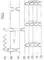
- the piezoelectric element 12 is energized by a pulse emitter 2 and the motor is controlled by a sawtooth scan signal generator (waveform (A), FIG. 2), so as to perform a sector scan of the region to be treated, scanning which passes through the focal point of the device emitting the treatment waves.
- waveform (A) sawtooth scan signal generator
- the pulses reflected by biological structures are amplified by a receiver 4 at the output of which is connected an analog-digital converter 5.
- An electronic switch 6 makes it possible to switch the output of the converter 5 to one or the other of two memories 61 and 62. The switching takes place on each scan, the switch 6 being, for this purpose, connected to an output scan generator 3.
- the addressing of the writing in each memory is controlled, in a manner known per se, as a function of the angular position of the beam emitted by the probe and of the time elapsed since the start of each emission, so that a complete image of the region treated is written to one of the two memories on each scan.
- the memories are read in a manner also known per se and the corresponding signals are applied via a switch 71 which reverses the connection between its inputs E 1 , E 2 and its outputs S 1 , S 2 at each scanning (being, for this purpose, connected to the appropriate output of the generator 3), to a digital subtractor 7.
- the subtractor which takes the difference between the serial digits which define the successive points of the two images, would successively perform the subtraction between the current image and the previous image, then between the previous image and the picture current, etc ..., hence the need for inversion to obtain, with each scan, the subtraction between the current image and the previous image.
- the output of the subtractor 7 is applied to a digital-analog converter 72, which supplies a brightness modulation voltage of the cathode-ray tube of the display device 8.
- the output S 2 is also connected to a second digital-analog converter 73 and a potentiometer 74 makes it possible to mix, in an adjustable proportion, the output voltage of the converter 72, which corresponds to the differential image and the output voltage of the converter 73, which corresponds to the last recorded image.
- the operator thus has the possibility of observing either the classic image of the region treated, which will allow him to carry out an initial identification of the structures, or the differential image, which will allow him to observe the evolution structures during treatment.
- the rate of image formation is sufficient so that the natural movements of the tissues under the influence of respiration do not introduce too great differences between two successive images, which would have the effect of masking the differential effect linked to the modification of the structures due to treatment.
- the duration of the transmission time can be chosen so as to obtain an image every 0.5 sec. at least. This implies that the peak power of the treatment emission is sufficient for significant destruction of the target cells to occur in a few tenths of a second.
- FIG. 2 represents in (C) the time intervals for writing to the memory 61, in (D) the time intervals for writing to the memory 62, in (E) the time intervals for reading from the memory 61, (F) the reading intervals in memory 62, in (G) and (H), the corresponding outputs S 1 and S 2 .
- the numbers of the images in memory have been indicated. We can see that the previous image is always subtracted from the current image.
- the emitter 10 of the processing wave which excites the power transducer T is also represented, symbolically represented in the form of a spherical cup on which piezoelectric elements are deposited.
- This transducer is advantageously produced in accordance with the indications of French patent No 84 06877 and the probe 1, although shown separately, will in practice be attached to the cup and arranged in its center and oriented along the axis thereof as indicated of said patent.
- the components include a frequency divider with adjustable division rate 9, an AND gate 11, a memory 12, a display device 13 and a switch 14.
- the divider 9 is connected to the scanning generator 3, which is arranged to provide a synchronization signal when the axis of the probe passes through the focal point of the transmitter of the treatment wave (center of the sphere of which the cup T constitutes a portion).
- the division rate of the divider is then set to a value ranging from 1 to 5 for example.
- This door is thus unlocked for 1/1000 sec. to transmit the digital signal from converter 5 to memory 12.
- the processing wave will only be interrupted for 1 ms only during the very duration of the processing wave trains, and this, every 1/20 sec. for example, which results in only a very small reduction (2% for example) of the average power compared to that of an uninterrupted treatment wave.
- the line thus acquired "on the fly”, every 1 to 5 scans, will be the one that passes through the focus. This is an A ultrasound and the information collected in one direction is sufficient. We could also obtain an equivalent result by immobilizing the probe in a determined direction crossing the target.
- the echoes stored in the memory 12 are read at a rate of 50 Hz for example and permanently displayed on the screen of the device 13.
- an ultrasound probe B to obtain type A echograms has the advantage of allowing the same probe to be used in ultrasound B before the treatment of a target (this term designating here a part of the tumor having a size identical to that of the focal spot and the complete treatment thereof consisting in focusing the beam successively on the different targets which constitute it), to locate said target in accordance with the methods described in the patent French No 84 06877 mentioned above. Relocation can even be carried out with the same probe, used in ultrasound B, during the treatment of a target, by interrupting it for a time sufficient to obtain an image (ie 1/20 of a second).
- the rise in temperature is linear for a duration t o which is substantially the same on the two curves, but corresponds to different temperatures, T o1 and T o2 respectively.
- the curves then bend to reach a plateau after an identical time of approximately 5 t 0 .
- the bearing temperature is approximately 3 T o1 for the first curve, 2.6 T o2 for the second.
- the apparatus is arranged so that the total destruction of the cells is obtained for a time at most equal to t o .
- the destruction time t of the tumor cells is proportional to the temperature T to which they are subjected, from a value T i thereof which is for example 43 ° C.
- T i 58 ° C
- t is of the order of 0.5 sec., So that the apparatus will be arranged to obtain a temperature of 58 ° C in the target.
- the application time t is substantially divided by 2 for each temperature rise of 1 ° C above 43 ° C, so that it is for example divided by 1000 when going from 50 ° to 60 ° C.
- the focal length is dictated by the depth of the target.
- the apparatus will be arranged to obtain three values of the focal distance, namely 4 to 15 cm (for the destruction of deep tumors), 3 to 4 cm (tumors with intermediate depth), 1 to 1, 5 cm (eye treatment for example).
- the working frequency will be determined so that the overall concentration of ultrasonic energy on the focal spot is maximum.
- the geometric concentration factor kg corresponds to the ratio of the intensities on the source and on the focal spot which would be obtained, in the absence of attenuation on the beam path, and it is therefore the factor ka which must be minimized if l 'We want to avoid energy losses in the tissues traversed, which incidentally only correspond to a small percentage of the energy absorbed by the tissues, and which is the only one to be transformed into heat.
- the Applicant has calculated the values of the overall concentration and of the residual energy in the focal spot, as well as of the speed of heating of the target, as a function of the focal distance, of the diameter of entry of the beam into the tissues and frequency, for a constant beam opening angle and a transmitted power of 1 Kw.
- the optimal frequency thus noted is 1 MHz and gives heating rates of 33.97 and 21.43 ° C per sec. respectively.
- the power should therefore theoretically be 1.2 and 1.9 Kw respectively to obtain the heating rate of 40 ° C / sec. desired.
- the optimal frequencies will be 3 and 1.5 MHz respectively, and the corresponding heating rates, of 384.89 and 135.91 ° C / sec.
- the theoretically necessary thermal powers will then be significantly less than 1 Kw. However, as a safety measure, we will take powers between 2 and 5 Kw.
- the optimal frequency will be 6 MHz and the heating value of 1539.57 ° C, which will lead in practice to take a power of the order of a few hundred watts.
- the peak powers used in ultrafast hyperthermia require that special measures be taken in the production of the device.
- piezoelectric ceramics capable of withstanding such peak powers and of cooling rapidly. Cooling devices may be required. Powering the electric generator may require the use of auxiliary sources.
- the acoustic waves undergo a notable progressive transformation during their propagation, the result of which is the appearance of components of frequencies higher than those of the starting wave.
- the frequencies and powers retained allow the waves to pass through the first layers of tissue with little alteration and to produce a thermal effect at the focal spot.
- these waves have a mechanical effect which is added to their thermal effect to increase the efficiency of the treatment.
Abstract
Description
Il est connu, en particulier du brevet français No 84 06877, déposé le 3 Mai 1984, pour : "Appareil d'examen et de localisation de tumeurs par ultrasons muni d'un dispositif de traitement localisé par hyperthermie", d'utiliser un faisceau ultrasonore focalisé pour provoquer un échauffement très localisé des tissus biologiques en vue de détruire les tumeurs.It is known, in particular from French patent No 84 06877, filed on May 3, 1984, for: "Apparatus for examining and locating tumors by ultrasound provided with a treatment device located by hyperthermia", using a beam focused ultrasound to cause very localized heating of biological tissue in order to destroy tumors.
Dans l'appareil décrit dans le brevet susvisé, l'émission de faisceau se fait par trains d'ondes à haute fréquence (0,5 à 5 MHz par exemple, les fréquences les plus basses étant utilisées pour la destruction des structures les plus profondes à l'intérieur du corps) et avec une puissance de crête relativement faible (une dizaine à une centaine de watts, les puissances les plus élevées étant utilisées pour la destruction des structures les plus profondes).In the apparatus described in the aforementioned patent, the beam emission is done by high frequency wave trains (0.5 to 5 MHz for example, the lowest frequencies being used for the destruction of the deepest structures inside the body) and with a relatively low peak power (ten to one hundred watts, the highest powers being used for the destruction of the deepest structures).
Ces trains d'ondes sont séparés par des intervalles pendant lesquels il est possible d'effectuer une échographie en temps réel, en général du type B permettant, soit d'effectuer une relocalisation du foyer par rapport à la cible (laquelle subit les mouvements naturels des tissus sous l'influence de la respiration), soit d'examiner les soit d'examiner les altérations subies par les tissus dans la zone traitée.These wave trains are separated by intervals during which it is possible to carry out an ultrasound in real time, in general of the type B allowing, either to carry out a relocation of the focus relative to the target (which undergoes natural movements tissues under the influence of respiration), or to examine the or to examine the alterations suffered by the tissues in the treated area.
Avec la puissance et les fréquences utilisées - qui sont fonction de la profondeur de la cible - la température de la cible est portée à 45°C environ, température suffisante en principe pour détruire les cellules malignes, et l'on a pensé jusqu'ici qu'une élévation de température excessive de la cible pourrait provoquer des brûlures graves dans la zone qui l'entoure, du fait de la diffusion thermique.With the power and the frequencies used - which are a function of the depth of the target - the temperature of the target is raised to around 45 ° C, a temperature sufficient in principle to destroy malignant cells, and we have thought so far that an excessive rise in temperature of the target could cause serious burns in the area around it, due to thermal diffusion.
Il en résulte que les temps de traitement sont relativement longs, leur durée pouvant atteindre plusieurs dizaines de minutes, voire plusieurs heures.As a result, the processing times are relatively long, their duration possibly reaching several tens of minutes, or even several hours.
Dans le document EP-A-0 370 841, est décrit un dispositif de traitement par ultrasons utilisant une céramique piézoélectrique focalisante et oscillante. Ce document propose d'utiliser des fréquences de traitement de l'ordre de 5 à 10 MHz, avec des puissances moyennes de l'ordre de 1 kW.In document EP-A-0 370 841, an ultrasound treatment device is described using a focusing and oscillating piezoelectric ceramic. This document proposes to use processing frequencies of the order of 5 to 10 MHz, with average powers of the order of 1 kW.
Le document US-A-3 735 755 décrit un procédé et un appareil de chirurgie non-invasive. Ce document donne, en fonction de la durée d'impulsion, l'intensité acoustique nécessaire pour produire des lésions dans la substance blanche du cerveau des mammifères.Document US-A-3,735,755 describes a method and apparatus for non-invasive surgery. This document gives, depending on the pulse duration, the acoustic intensity necessary to produce lesions in the white matter of the mammalian brain.
Le document GB-B-820 814 décrit un appareil de traitement des tissus par ultrasons. Ce document propose d'utiliser des fréquences de traitement de l'ordre de 1 MHz, avec des intensité de l'ordre de 10 à 1000 W/cm2.GB-B-820 814 describes an ultrasonic tissue treatment apparatus. This document proposes to use processing frequencies of the order of 1 MHz, with intensities of the order of 10 to 1000 W / cm 2 .
Ces documents n'indiquent pas précisément, comme le fait l'invention, comment déterminer les paramètres qui définissent la concentration globale du faisceau ultrasonore dans la tache focale et la puissance, de façon à optimiser la durée du traitement, et limiter les brûlures dans la zone qui entoure la cible.These documents do not indicate precisely, as does the invention, how to determine the parameters which define the overall concentration of the ultrasonic beam in the focal spot and the power, so as to optimize the duration of the treatment, and limit burns in the area surrounding the target.
L'invention repose sur la découverte du fait que la multiplication de puissance de crête des ondes utilisées par un facteur allant de 10 à 100 en fonction de la profondeur et du pouvoir absorbant de la cible permet au contraire, en provoquant une élévation de température ultrarapide, de réduire notablement les effets de la diffusion thermique et d'aboutir à une destruction de la cible en des temps de l'ordre de la seconde.The invention is based on the discovery of the fact that the multiplication of peak power of the waves used by a factor ranging from 10 to 100 depending on the depth and the absorbency of the target allows on the contrary, by causing an ultrafast temperature rise , significantly reduce the effects of thermal diffusion and lead to destruction of the target in times of the order of a second.
L'invention propose un appareil d'hyperthermie ultrasonore extracorporelle, permettant l'émission focalisée de trains d'ondes ultrasonores à différentes profondeurs, caractérisé en ce que les dits trains d'ondes ultrasonores présentent une fréquence comprise entre 0,5 et 10 MHz et des puissances électriques de crête comprises entre 10 kW et quelques centaines de watts, les paramètres qui définissent la concentration globale du faisceau ultrasonore dans la tache focale et la puissance étant déterminés pour que, quelle que soit la profondeur et la nature des tissus, le temps de l'émission de traitement soit de l'ordre de celui qui permet d'atteindre une température de destruction de la cible pendant la partie linéaire de la courbe d'élévation de température de celle-ci en fonction du temps.The invention provides an extracorporeal ultrasonic hyperthermia apparatus, allowing the focused emission of ultrasonic wave trains at different depths, characterized in that said ultrasonic wave trains have a frequency between 0.5 and 10 MHz and peak electrical powers between 10 kW and a few hundred watts, the parameters which define the overall concentration of the ultrasonic beam in the focal spot and the power being determined so that, whatever the depth and the nature of the tissues, the time of the treatment emission is of the order of that which makes it possible to reach a temperature of destruction of the target during the linear part of the temperature rise curve thereof as a function of time.
Avantageusement, la fréquence ainsi que le diamètre de la surface émettrice dudit appareil et celui de la tache focale sont déterminés en fonction de la nature et de la profondeur de la cible, pour que le facteur de concentration globale du faisceau soit maximal et la puissance est alors déterminée pour une valeur donnée de la fréquence et des diamètres sélectionnés, pour que la destruction de la cible s'effectue à une température voisine de 58°C, en un temps compris entre 0,5 et 3 sec.Advantageously, the frequency as well as the diameter of the emitting surface of said device and that of the focal spot are determined as a function of the nature and the depth of the target, so that the overall concentration factor of the beam is maximum and the power is then determined for a given value of the frequency and the diameters selected, so that the destruction of the target takes place at a temperature in the region of 58 ° C, in a time of between 0.5 and 3 sec.
Les essais effectués par la Demanderesse ont permis de constater que cet agencement de l'appareil, lequel requiert la mise en oeuvre de moyens appropriés à l'émission quasi-continue de puissances de crête très élevées, permet de minimiser la destruction des cellules saines tout en augmentant l'efficacité de la destruction de la cible, en particulier par un effet supplémentaire de destruction mécanique des cellules de celles-ci, et aboutit ainsi à une nouvelle technique d'hyperthermie ultrasonore localisée qui justifie le terme d'hyperthermie ultrarapide qui la désignera ci-après.The tests carried out by the Applicant have shown that this arrangement of the apparatus, which requires the use of means suitable for the quasi-continuous emission of very high peak powers, makes it possible to minimize the destruction of healthy cells while by increasing the efficiency of the destruction of the target, in particular by an additional effect of mechanical destruction of the cells thereof, and thus results in a new technique of localized ultrasonic hyperthermia which justifies the term of ultrafast hyperthermia which will designate below.
Un autre avantage de l'hyperthermie ultrarapide est qu'elle permet d'améliorer considérablement l'examen échographique des altérations de la cible au cours du traitement.Another advantage of ultrafast hyperthermia is that it considerably improves the ultrasound examination of target alterations during treatment.
Suivant un autre aspect de l'invention, cet examen est effectué par échographie A ou B pendant des interruptions de l'onde de traitement effectuées à une cadence déterminée pour que l'échogramme ou respectivement l'image aient eu le temps de subir des modifications détectables (ce qui pourra être le cas en quelques dixièmes de secondes en hyperthermie ultrarapide), non masquées par les modifications parasites provoquées par le mouvement des trains (comme c est en pratique le cas dans l'hyperthermie de l'art antérieur).According to another aspect of the invention, this examination is carried out by ultrasound A or B during interruptions of the treatment wave carried out at a determined rate so that the echogram or the image respectively have had time to undergo modifications. detectable (which could be the case in a few tenths of seconds in ultra-fast hyperthermia), not masked by the parasitic modifications caused by the movement of the trains (as is in practice the case in hyperthermia of the prior art).
L'invention porte par ailleurs sur des techniques particulières d'échographie A ou B qui facilitent la détection ultrarapide des altérations subies par la cible et permettent ainsi d'arrêter le traitement dès sa destruction.The invention also relates to particular ultrasound techniques A or B which facilitate the ultra-rapid detection of alterations undergone by the target and thus make it possible to stop the treatment as soon as it is destroyed.
L'invention porte enfin sur un procédé de détermination des paramètres de réglages d'un appareil d'hyperthermie ultrasonore extracorporelle, comprenant les étapes consistant à:
- déterminer la distance focale à partir de la profondeur de la dite cible;
- choisir la fréquence des trains d'ondes ultrasonores dans une plage entre 0,5 et 10 MHz pour que la concentration globale de l'énergie ultrasonore soit maximale sur la tache focale, à la distance focale déterminée;
- déterminer expérimentalement la durée de la partie linéaire de la montée en température;
- choisir la puissance électrique de crête dans une plage entre quelques centaines de watts et 10 kW, pour atteindre une température de destruction de la cible pendant la partie linéaire de la courbe d'élévation de température.
- determining the focal distance from the depth of said target;
- choosing the frequency of the ultrasonic wave trains in a range between 0.5 and 10 MHz so that the overall concentration of the ultrasonic energy is maximum on the focal spot, at the determined focal distance;
- experimentally determining the duration of the linear part of the temperature rise;
- choose the peak electrical power in a range between a few hundred watts and 10 kW, to reach a target destruction temperature during the linear part of the temperature rise curve.
D'autres particularités, ainsi que les avantages de l'invention apparaîtront clairement à la lumière de la description ci-après, dans laquelle les techniques de détection ultrarapide ont été décrites en premier, afin de facilité l'exposé ultérieur de l'agencement de l'appareil qui permet l'hyperthermie ultrarapide.Other particularities, as well as the advantages of the invention will become clear in the light of the description below, in which the ultrafast detection techniques have been described first, in order to facilitate the subsequent discussion of the arrangement of the device that allows ultrafast hyperthermia.
Au dessin annexé :
- La figure 1 représente schématiquement un appareil d'hyperthermie ultrarapide muni de moyens de détection ultrarapide des altérations de la cible en cours de traitement ;
- La figure 2 est un diagramme destiné a illustrer le fonctionnement desdits moyens de détection ; et
- La figure 3 représente les courbes d'élévation de la température d'un tissu biologique en fonction du temps.
- FIG. 1 schematically represents an ultrafast hyperthermia apparatus provided with ultrafast detection means for alterations of the target during treatment;
- FIG. 2 is a diagram intended to illustrate the operation of said detection means; and
- FIG. 3 represents the curves of elevation of the temperature of a biological tissue as a function of time.
A la figure 1, on a représenté schématiquement un échographe de type connu comprenant une sonde temps réel 1 comportant un élément piézoélectrique 12 entraîné en oscillation par un moteur électrique 13, par l'intermédiaire d'un système de transmission symbolisé par une ligne en trait mixte.In Figure 1, there is schematically shown a known type of ultrasound system comprising a
A titre d'exemple, cette sonde peut être réalisée suivant la description donnée dans le brevet français No 80 16718, déposé le 29 Juillet 1980, pour : "Sonde d'échographie à balayage sectoriel mécanique".By way of example, this probe can be produced according to the description given in French patent No 80 16718, filed on July 29, 1980, for: "Mechanical sectoral scanning ultrasound probe".
L'élément piézoélectrique 12 est excité par un émetteur d'impulsions 2 et le moteur est commandé par un générateur de signaux de balayage en dents de scie (forme d'onde (A), figure 2), de manière à effectuer un balayage sectoriel de la région à traiter, balayage qui passe par le foyer du dispositif émetteur des ondes de traitement.The
Les impulsions réfléchies par les structures biologiques sont amplifiées par un récepteur 4 à la sortie duquel est relié un convertisseur analogique-numérique 5.The pulses reflected by biological structures are amplified by a receiver 4 at the output of which is connected an analog-digital converter 5.
Un commutateur électronique 6 permet d'aiguiller la sortie du convertisseur 5 sur l'une ou l'autre de deux mémoires 61 et 62. La commutation s'effectue à chaque balayage, le commutateur 6 étant, à cet effet, relié à une sortie appropriée du générateur de balayage 3.An electronic switch 6 makes it possible to switch the output of the converter 5 to one or the other of two
L'adressage de l'écriture dans chaque mémoire est commandé, de façon connue en soi, en fonction de la position angulaire du faisceau émis par la sonde et du temps écoulé depuis le début de chaque émission, pour qu'une image complète de la région traitée soit inscrite dans l'une des deux mémoires à chaque balayage.The addressing of the writing in each memory is controlled, in a manner known per se, as a function of the angular position of the beam emitted by the probe and of the time elapsed since the start of each emission, so that a complete image of the region treated is written to one of the two memories on each scan.
La lecture des mémoires s'effectue de façon également connue en soi et les signaux correspondant sont appliqués par l'intermédiaire d'un commutateur 71 qui inverse la connexion entre ses entrées E1, E2 et ses sorties S1, S2 à chaque balayage (étant, à cet effet, relié à la sortie appropriée du générateur 3), à un soustracteur numérique 7.The memories are read in a manner also known per se and the corresponding signals are applied via a
En l'absence de l'inversion, le soustracteur, qui prend la différence entre les digits série qui définissent les points successifs des deux images, effectuerait successivement la soustraction entre l'image actuelle et l'image précédente, puis entre l'image précédente et l'image actuelle, etc..., d'où la nécessité de l'inversion pour obtenir, à chaque balayage, la soustraction entre l'image actuelle et l'image précédente.In the absence of the inversion, the subtractor, which takes the difference between the serial digits which define the successive points of the two images, would successively perform the subtraction between the current image and the previous image, then between the previous image and the picture current, etc ..., hence the need for inversion to obtain, with each scan, the subtraction between the current image and the previous image.
La sortie du soustracteur 7 est appliquée à un convertisseur numérique-analogique 72, qui fournit une tension de modulation de brillance du tube cathodique du dispositif de visualisation 8.The output of the subtractor 7 is applied to a digital-
La sortie S2 est par ailleurs reliée à un second convertisseur numérique-analogique 73 et un potentiomètre 74 permet de mélanger, dans une proportion réglable, la tension de sortie du convertisseur 72, qui correspond à l'image différentielle et la tension de sortie du convertisseur 73, qui correspond à la dernière image enregistrée.The output S 2 is also connected to a second digital-
L'opérateur a ainsi la possibilité d'observer, soit l'image classique de la région traitée, ce qui lui permettra d'effectuer une première identification des structures, soit l'image différentielle, ce qui lui permettra d'observer l'évolution des structures au cours du traitement.The operator thus has the possibility of observing either the classic image of the region treated, which will allow him to carry out an initial identification of the structures, or the differential image, which will allow him to observe the evolution structures during treatment.
Comme le traitement s'effectue avec des puissances de crête élevées, la formation des images ne peut avoir lieu pendant l'émission des ondes de traitement, l'énergie de ces ondes, réfléchie par les structures, étant suffisante pour éblouir le transducteur échographique. Cet éblouissement peut se prolonger une ou plusieurs microsecondes après la fin de l'émission. Il est donc nécessaire d'effectuer l'émission par trains d'ondes séparés par des temps morts (forme d'onde (B), figure 2) un peu supérieurs à la durée d'un balayage échographique, lequel dure par exemple, 1/20 sec. et de synchroniser ce dernier avec l'émission.As the processing is carried out with high peak powers, the formation of the images cannot take place during the emission of the processing waves, the energy of these waves, reflected by the structures, being sufficient to dazzle the ultrasound transducer. This glare can continue one or more microseconds after the end of the emission. It is therefore necessary to perform the emission by wave trains separated by dead times (waveform (B), Figure 2) slightly greater than the duration of an ultrasound scan, which lasts for example, 1 / 20 sec. and synchronize it with the broadcast.
Il est évidemment nécessaire, par ailleurs, que la cadence de formation des images soit suffisante pour que les mouvements naturels des tissus sous l'influence de la respiration n'introduisent pas de trop grandes différences entre deux images successives, ce qui aurait pour effet de masquer l'effet différentiel lié à la modification des structures due au traitement. A titre d'exemple, on pourra choisir la durée du temps d'émission de façon à obtenir une image tous les 0,5 sec. au moins. Ceci implique que la puissance de crête de l'émission de traitement soit suffisante pour qu'une destruction significative des cellules de la cible se produise en quelques dixièmes de seconde.It is obviously necessary, moreover, that the the rate of image formation is sufficient so that the natural movements of the tissues under the influence of respiration do not introduce too great differences between two successive images, which would have the effect of masking the differential effect linked to the modification of the structures due to treatment. By way of example, the duration of the transmission time can be chosen so as to obtain an image every 0.5 sec. at least. This implies that the peak power of the treatment emission is sufficient for significant destruction of the target cells to occur in a few tenths of a second.
La figure 2 représente en (C) les intervalles de temps d'écriture dans la mémoire 61, en (D) les intervalles de temps d'écriture dans la mémoire 62, en (E) les intervalles de lecture de la mémoire 61, en (F) les intervalles de lecture dans la mémoire 62, en (G) et (H), les sorties S1 et S2 correspondantes. Les numéros des images en mémoire ont été indiqués. On voit ainsi que l'image précédente est toujours soustraite de l'image actuelle.FIG. 2 represents in (C) the time intervals for writing to the
Revenant à la figure 1, on a représenté en outre l'émetteur 10 de l'onde de traitement qui excite le transducteur de puissance T, représenté symboliquement sous la forme d'une coupelle sphérique sur laquelle sont déposés des éléments piézoélectriques. Ce transducteur est avantageusement réalisé conformément aux indications du brevet français No 84 06877 et la sonde 1, bien que figurée à part, sera en pratique solidarisée à la coupelle et disposée en son centre et orientée suivant l'axe de celle-ci suivant les indications dudit brevet.Returning to FIG. 1, the
Par ailleurs, on a représenté à la figure 1 des organes qui ne sont pas utilisés dans le mode d'exécution de l'invention décrit jusqu'ici, mais seulement dans la variante qui va maintenant être décrite.Furthermore, there is shown in Figure 1 organs which are not used in the embodiment of the invention described so far, but only in the variant which will now be described.
Les organes comprennent un diviseur de fréquence à taux de division réglable 9, une porte ET 11, une mémoire 12, un dispositif de visualisation 13 et un commutateur 14.The components include a frequency divider with adjustable division rate 9, an
Lorsque le commutateur 14 est en position a, le diviseur 9 est connecté au générateur de balayage 3, lequel est agencé pour fournir un signal de synchronisation lorsque l'axe de la sonde passe par le foyer de l'émetteur de l'onde de traitement (centre de la sphère dont la coupelle T constitue une portion). Le taux de division du diviseur est alors réglé à une valeur allant de 1 à 5 par exemple.When the
Il fournit donc tous les N balayages, un signal bref appliqué d'une part à l'émetteur de puissance 10, qu'il va bloquer pendant sa durée d'environ 1 ms, d'autre part, à la porte 11.It therefore provides all the N scans, a brief signal applied on the one hand to the
Cette porte se trouve ainsi débloquée pendant 1/1000 sec. pour transmettre à la mémoire 12 le signal numérique issu du convertisseur 5.This door is thus unlocked for 1/1000 sec. to transmit the digital signal from converter 5 to
Celle-ci a aussi le temps d'acquérir l'information correspondant à une ligne de balayage, dont la durée est seulement de l'ordre de 0,2 ms (contre 0,2 à 0,02 sec. pour l'acquisition d'une image complète).It also has time to acquire the information corresponding to a scan line, the duration of which is only of the order of 0.2 ms (against 0.2 to 0.02 sec. For the acquisition of 'a full picture).
Ainsi, dans cette variante, l'onde de traitement ne sera interrompue que pendant 1 ms seulement pendant la durée même des trains d'ondes de traitement, et ce, toutes les 1/20 sec. par exemple, ce qui n'entraîne qu'une réduction très faible (2 % par exemple) de la puissance moyenne par rapport à celle d'une onde de traitement non interrompue.Thus, in this variant, the processing wave will only be interrupted for 1 ms only during the very duration of the processing wave trains, and this, every 1/20 sec. for example, which results in only a very small reduction (2% for example) of the average power compared to that of an uninterrupted treatment wave.
La ligne ainsi acquise "au vol", tous les 1 à 5 balayages, sera celle qui passe par le foyer. Il s'agit d'échographie A et l'information recueillie dans une seule direction est suffisante. On pourrait d'ailleurs obtenir un résultat équivalent en immobilisant la sonde suivant une direction déterminée traversant la cible.The line thus acquired "on the fly", every 1 to 5 scans, will be the one that passes through the focus. This is an A ultrasound and the information collected in one direction is sufficient. We could also obtain an equivalent result by immobilizing the probe in a determined direction crossing the target.
Les échos stockés dans la mémoire 12 sont lus à une cadence de 50 Hz par exemple et affichés en permanence sur l'écran du dispositif 13.The echoes stored in the
Cette cadence de lecture donne un bon confort visuel.This reading rate gives good visual comfort.
On notera que c'est ici l'oeil de l'opérateur qui effectue l'équivalent de la soustraction numérique des informations recueillies pendant le traitement, à une cadence telle qu'il puisse apprécier les changements d'amplitude de l'échogramme.It will be noted that it is here the operator's eye which performs the equivalent of the digital subtraction of the information collected during the processing, at a rate such that it can appreciate the changes in amplitude of the echogram.
Il doit être bien compris que l'utilisation d'une sonde d'échographie B pour obtenir des échogrammes du type A présente l'avantage de permettre d'utiliser la même sonde en échographie B avant le traitement d'une cible (ce terme désignant ici une partie de la tumeur ayant une dimension identique à celle de la tache focale et le traitement complet de celle-ci consistant à focaliser le faisceau successivement sur les différentes cibles qui la constituent), pour localiser ladite cible conformément aux procédés décrits dans le brevet français No 84 06877 susvisé. Une relocalisation peut même être effectuée avec la même sonde, utilisée en échographie B, pendant le traitement d'une cible, en interrompant celui-ci pendant un temps suffisant pour obtenir une image (soit 1/20 de sec.).It should be understood that the use of an ultrasound probe B to obtain type A echograms has the advantage of allowing the same probe to be used in ultrasound B before the treatment of a target (this term designating here a part of the tumor having a size identical to that of the focal spot and the complete treatment thereof consisting in focusing the beam successively on the different targets which constitute it), to locate said target in accordance with the methods described in the patent French No 84 06877 mentioned above. Relocation can even be carried out with the same probe, used in ultrasound B, during the treatment of a target, by interrupting it for a time sufficient to obtain an image (
Les autres agencements de l'appareil qui permettent l'hyperthermie ultrarapide vont maintenant être expliqués en se référant à la figure 3.The other arrangements of the apparatus which allow ultrafast hyperthermia will now be explained with reference to FIG. 3.
Celle-ci représente, pour une source calorifique de faible volume, (ici, tache focale de faible diamètre), la montée en température T expérimentalement constatée de la zone soumise aux ondes ultrasonores, en fonction du temps d'application de celles-ci, pour deux valeurs différentes de la puissance appliquée (courbes I et II).This represents, for a calorific source of small volume, (here, focal spot of small diameter), the rise in temperature T experimentally observed of the zone subjected to ultrasonic waves, as a function of the time of application of these, for two different values of the applied power (curves I and II).
On voit que la montée en température est linéaire pendant une durée to qui est sensiblement la même sur les deux courbes, mais correspond à des températures différentes, To1 et To2 respectivement. Les courbes s'infléchissent ensuite pour atteindre un palier au bout d'un temps identique environ égal à 5 to. La température du palier est environ 3 To1 pour la première courbe, 2,6 To2 pour la seconde.We see that the rise in temperature is linear for a duration t o which is substantially the same on the two curves, but corresponds to different temperatures, T o1 and T o2 respectively. The curves then bend to reach a plateau after an identical time of approximately 5 t 0 . The bearing temperature is approximately 3 T o1 for the first curve, 2.6 T o2 for the second.
On constate que to est indépendant de la puissance appliquée, et d'autant plus faible que le diamètre de la tache focale est plus réduit. Dans les conditions expérimentales qui ont abouti aux courbes représentées, to = 0,5 sec.It can be seen that t o is independent of the power applied, and the smaller the smaller the diameter of the focal spot. Under the experimental conditions which led to the curves shown, t o = 0.5 sec.
Suivant un mode d'exécution préféré de l'invention, on agence l'appareil pour que la destruction totale des cellules soit obtenue pendant un temps au plus égal à to.According to a preferred embodiment of the invention, the apparatus is arranged so that the total destruction of the cells is obtained for a time at most equal to t o .
La Demanderesse a constaté qu'il en résulte un endommagement minimal des tissus de la région qui entoure la cible.The Applicant has found that this results in minimal damage to the tissues of the region which surrounds the target.
Ce résultat expérimental peut s'expliquer par le fait que, dans la région linéaire de la courbe, les pertes par diffusion sont négligeables devant l'apport en calories. Au-delà, entre le point d'inflexion de la courbe, lesdites pertes deviennent proportionnelles au gradient de température entre la cible et les tissus voisins, augmentant ainsi rapidement, jusqu'à devenir égale à l'apport de calories (au palier). Lorsque l'apport de calories cesse, la température de la cible décroît suivant une courbe d'allure exponentielle et atteint une valeur pour laquelle il n'y a sensiblement plus de destruction au bout d'un temps de l'ordre de 3 à 6 to dans les conditions expérimentales considérées. Ce temps (ici de l'ordre de 1,5 à 3 sec.) définira sensiblement celui de l'interruption préférentielle entre deux trains successifs d'ondes de traitement, qui permet que les trains successifs agissent tous dans des conditions de pertes minimales par diffusion.This experimental result can be explained by the fact that, in the linear region of the curve, the diffusion losses are negligible compared to the calorie intake. Beyond this, between the point of inflection of the curve, said losses become proportional to the temperature gradient between the target and the neighboring tissues, thus increasing rapidly, until it becomes equal to the intake of calories (at the plateau). When the intake of calories ceases, the temperature of the target decreases along an exponential curve and reaches a value for which there is noticeably more destruction at after a time of the order of 3 to 6 t 0 under the experimental conditions considered. This time (here of the order of 1.5 to 3 sec.) Will substantially define that of the preferential interruption between two successive trains of processing waves, which allows the successive trains all to act under conditions of minimum losses by diffusion.
Il en résulte, qu'à la figure 2, où la durée du train est un peu inférieure à 0,5 sec., valeur choisie parce qu'elle correspond à to, les trains successifs, séparés ici par des intervalles de 0,05 sec. seulement, seront de préférence appliqués à des cibles différentes dans la tumeur, un seul train suffisant pour comparer l'état de réflexivité de chaque cible avant et après son application.As a result, in FIG. 2, where the duration of the train is a little less than 0.5 sec., A value chosen because it corresponds to t o , the successive trains, separated here by intervals of 0, 05 sec. only, will preferably be applied to different targets in the tumor, a single train sufficient to compare the state of reflexivity of each target before and after its application.
Il est connu par ailleurs que le temps de destruction t des cellules tumorales est proportionnel à la température T à laquelle elles sont soumises, à partir d'une valeur Ti de celle-ci qui est par exemple de 43°C. Pour T = 58°C, t est de l'ordre de 0,5 sec., si bien que l'appareil sera agencé pour obtenir une température de 58°C dans la cible. Le temps d'application t est sensiblement divisé par 2 pour chaque élévation de température de 1°C au-dessus de 43°C, si bien qu'il est par exemple divisé par 1000 quand on passe de 50° à 60°C.It is also known that the destruction time t of the tumor cells is proportional to the temperature T to which they are subjected, from a value T i thereof which is for example 43 ° C. For T = 58 ° C, t is of the order of 0.5 sec., So that the apparatus will be arranged to obtain a temperature of 58 ° C in the target. The application time t is substantially divided by 2 for each temperature rise of 1 ° C above 43 ° C, so that it is for example divided by 1000 when going from 50 ° to 60 ° C.
Pour obtenir cette élévation de la température de la cible à environ 20°C au-dessus de la normale en 0,5 sec., soit une vitesse d'échauffement de 40°C/sec., les paramètres suivants sont pris en considération : tout d'abord, la distance focale est imposée par la profondeur de la cible. A titre d'exemple, l'appareil sera agencé pour obtenir trois valeurs de la distance focale, à savoir 4 à 15 cm (pour la destruction de tumeurs profondes), 3 à 4 cm (tumeurs à profondeur intermédiaire), 1 à 1,5 cm (traitement de l'oeil par exemple).To obtain this increase in target temperature to around 20 ° C above normal in 0.5 sec., I.e. a heating rate of 40 ° C / sec., The following parameters are taken into account: first, the focal length is dictated by the depth of the target. For example, the apparatus will be arranged to obtain three values of the focal distance, namely 4 to 15 cm (for the destruction of deep tumors), 3 to 4 cm (tumors with intermediate depth), 1 to 1, 5 cm (eye treatment for example).
Pour chaque distance focale, la fréquence de travail sera déterminée pour que la concentration globale de l'énergie ultrasonore sur la tache focale soit maximale.For each focal distance, the working frequency will be determined so that the overall concentration of ultrasonic energy on the focal spot is maximum.
L'expérience montre en effet que c'est lorsque cette première condition est réalisée que, pour une puissance d'émission donnée, les risques d'endommagement des tissus voisins sont minimisés, tandis que la densité d'énergie au niveau de la tache focale est maximale.Experience indeed shows that it is when this first condition is achieved that, for a given transmission power, the risks of damage to neighboring tissues are minimized, while the energy density at the focal spot is maximum.
Cette constatation peut s'expliquer si l'on considère que cette concentration globale est le produit kg/ka, ka étant un facteur d'atténuation d'autant plus grand que la fréquence est plus élevée (l'expérience montre que l'atténuation est de l'ordre de 1°C par cm de trajet et par MHz) et kg étant égal à![]()
![]()
Le facteur de concentration géométrique kg correspond au rapport des intensités sur la source et sur la tache focale qui serait obtenu, en l'absence d'atténuation sur le trajet du faisceau, et c'est donc le facteur ka qui doit être minimisé si l'on veut éviter les pertes d'énergie dans les tissus traversés, lesquelles ne correspondent d'ailleurs que pour un faible pourcentage à de l'énergie absorbée par les tissus, et qui est la seule à être transformée en chaleur.The geometric concentration factor kg corresponds to the ratio of the intensities on the source and on the focal spot which would be obtained, in the absence of attenuation on the beam path, and it is therefore the factor ka which must be minimized if l 'We want to avoid energy losses in the tissues traversed, which incidentally only correspond to a small percentage of the energy absorbed by the tissues, and which is the only one to be transformed into heat.
La Demanderesse a calculé les valeurs de la concentration globale et de l'énergie résiduelle dans la tache focale, ainsi que de la vitesse d'échauffement de la cible, en fonction de la distance focale, du diamètre d'entrée du faisceau dans les tissus et de la fréquence, pour un angle d'ouverture constant en faisceau et une puissance émise de 1 Kw.The Applicant has calculated the values of the overall concentration and of the residual energy in the focal spot, as well as of the speed of heating of the target, as a function of the focal distance, of the diameter of entry of the beam into the tissues and frequency, for a constant beam opening angle and a transmitted power of 1 Kw.
Ces calculs montrent que l'énergie résiduelle croît en raison inverse de la fréquence, mais que l'énergie résiduelle maximum ne correspond pas à la concentration globale maximale, donc à l'échauffement le plus rapide.These calculations show that the residual energy increases in inverse ratio to the frequency, but that the maximum residual energy does not correspond to the maximum overall concentration, therefore to the fastest heating.
Cette constatation peut s'expliquer par le fait que la fréquence agit en sens inverse sur ka et la vitesse d'échauffement d'une part, sur kg d'autre part.This observation can be explained by the fact that the frequency acts in the opposite direction on ka and the speed of heating on the one hand, on kg on the other hand.
A titre d'exemple, pour une énergie émise de 1 Kw, des distances focales respectives de 10 et 12 cm, avec des diamètres d'entrée dans les tissus de 10 et 12 cm respectivement, la fréquence optimale ainsi relevée est de 1 MHz et donne des vitesses d'échauffement de 33,97 et 21,43°C par sec. respectivement. La puissance devrait donc théoriquement être égale à 1,2 et 1,9 Kw respectivement pour obtenir la vitesse d'échauffement de 40°C/sec. souhaitée. A titre de sécurité, on travaillera à une puissance sensiblement supérieure à ces valeurs, de l'ordre de 10 Kw par exemple, pour tenir compte du fait que la température de 58°C ne sera atteinte qu'à la fin de chaque impulsion du train d'ondes de traitement.For example, for an emitted energy of 1 Kw, respective focal distances of 10 and 12 cm, with tissue entry diameters of 10 and 12 cm respectively, the optimal frequency thus noted is 1 MHz and gives heating rates of 33.97 and 21.43 ° C per sec. respectively. The power should therefore theoretically be 1.2 and 1.9 Kw respectively to obtain the heating rate of 40 ° C / sec. desired. For safety, we will work at a power significantly higher than these values, of the order of 10 Kw for example, to take into account the fact that the temperature of 58 ° C will only be reached at the end of each pulse of the processing wave train.
Toutes choses égales par ailleurs, pour des distances focales de 3 et 5 cm et des diamètres d'entrées respectives de 3 et 5 cm, les fréquences optimales seront de 3 et 1,5 MHz respectivement, et les vitesses d'échauffement correspondantes, de 384,89 et 135,91°C/sec. Les puissances thermiques théoriquement nécessaires seront alors sensiblement inférieures à 1 Kw. Cependant, par mesure de sécurité, on prendra des puissances comprises entre 2 et 5 Kw.All other things being equal, for focal lengths of 3 and 5 cm and respective input diameters of 3 and 5 cm, the optimal frequencies will be 3 and 1.5 MHz respectively, and the corresponding heating rates, of 384.89 and 135.91 ° C / sec. The theoretically necessary thermal powers will then be significantly less than 1 Kw. However, as a safety measure, we will take powers between 2 and 5 Kw.
Pour une distance focale de 1,5 cm, la fréquence optimale sera de 6 MHz et la valeur d'échauffement de 1539,57°C, ce qui conduira en pratique à prendre une puissance de l'ordre de quelques centaines de watts.For a focal distance of 1.5 cm, the optimal frequency will be 6 MHz and the heating value of 1539.57 ° C, which will lead in practice to take a power of the order of a few hundred watts.
D'une façon générale, les puissances de crête utilisées en hyperthermie ultrarapide, surtout si l'on souhaite pouvoir traiter les tumeurs profondes, exigent que des mesures particulières soient prises dans la réalisation de l'appareil. Il faudra notamment utiliser des céramiques piézoélectriques capables de supporter de telles puissances de crête et de se refroidir rapidement. Des dispositifs de refroidissement pourront être nécessaires. L'alimentation du générateur électrique pourra requérir l'emploi de sources auxiliaires.In general, the peak powers used in ultrafast hyperthermia, especially if one wishes to be able to treat deep tumors, require that special measures be taken in the production of the device. In particular, it will be necessary to use piezoelectric ceramics capable of withstanding such peak powers and of cooling rapidly. Cooling devices may be required. Powering the electric generator may require the use of auxiliary sources.
On notera que les valeurs optimales de puissance indiquées ne devront pas être dépassées de manière excessive si l'on veut éviter le risque de lésions des tissus voisins. En effet, on a pu montrer que le diamètre de la zone à l'intérieur de laquelle l'élévation de température qui résulte de la diffusion des calories accumulées dans la région focale à l'instant où cesse l'application de la puissance reste suffisante pour détruire les cellules relativement rapidement croît comme la racine carrée de l'élévation de la température dans la région focale, élévation elle-même proportionnelle à la puissance.It should be noted that the optimum power values indicated should not be exceeded excessively if the risk of damage to neighboring tissues is to be avoided. In fact, we have been able to show that the diameter of the zone inside which the rise in temperature which results from the diffusion of the calories accumulated in the focal region at the moment when the application of power ceases remains sufficient to destroy cells relatively quickly grows as the square root of the temperature rise in the focal region, which itself is proportional to the power.
On notera enfin qu'aux puissances indiquées, les ondes acoustiques subissent une transformation progressive notable au cours de leur propagation, dont le résultat est l'apparition de composants de fréquences plus élevées que celles de l'onde de départ.Finally, it should be noted that at the indicated powers, the acoustic waves undergo a notable progressive transformation during their propagation, the result of which is the appearance of components of frequencies higher than those of the starting wave.
Ces composants à fréquence élevée sont plus fortement absorbés par les tissus et ont donc un effet thermique plus important.These high frequency components are more strongly absorbed by the tissues and therefore have a greater thermal effect.
Les fréquences et les puissances retenues permettent aux ondes de traverser avec peu d'altération les premières couches de tissus et de produire un effet thermique au niveau de la tache focale.The frequencies and powers retained allow the waves to pass through the first layers of tissue with little alteration and to produce a thermal effect at the focal spot.
Par ailleurs, ces ondes ont un effet mécanique qui s'ajoute à leur effet thermique pour augmenter l'efficacité du traitement.Furthermore, these waves have a mechanical effect which is added to their thermal effect to increase the efficiency of the treatment.
Claims (12)
- An extracorporeal ultrasound hyperthermia treatment device adapted to enable the focussed emission of ultrasound wave trains at varying depths, characterized in that said ultrasound wave trains are of a frequency comprised between 0.5 and 10 MHz with electrical power peaks of between 10 kW and a few hundred watts, the parameters defining overall ultrasound beam concentration in the focal spot and power being determined whereby, irrespective of the depth and nature of the tissue, the treatment emission time is of the order of the time needed to reach a temperature at which the target is destroyed during the linear portion of the curve showing target temperature increase as a function of time.
- Device according to claim 1, characterized in that the frequency and the diameter of the emitting surface of said device and the diameter the focal spot are determined according to the nature and the depth of the target so that the overall concentration factor of the treatment beam is maximized and the power is then determined for a given value of the frequency and for selected diameters, whereby target destruction takes place at a temperature in the vicinity of 58°C in a time period comprised between 0.5 and 3 seconds.
- Device according to claim 1 or 2, characterized in that the wave trains successively applied to a given target are separated by time periods of the order of 1.5 to 3 seconds.
- Device according to one of claims 1 to 3 characterized by an emission power of the order of 10 kW for focal lengths of 10 and 12 cm and an optimum frequency of 1 MHz, an electrical emission power of between 2 and 5 kW for focal lengths of 3 and 5 cm and optimum frequencies of 3 and 1.5 MHz, respectively, and an electrical emission power of the order of several hundreds of watts for a focal length of 1.5 cm and an optimum frequency of 6 MHz.
- Device according to one of claims 1 to 4, comprising means for echographic examination of changes occurring at the target during treatment, characterized in that said means execute type B echography of the target and are adapted to compare two consecutive images taken before and after at least one treatment wave train.
- Device according to claim 5, characterized by means for storing successive images in the form of digital information and for forming a differential image by point-by-point subtraction of the stored information.
- Device according to claim 6, characterized by means for superimposing one of the stored image on the differential image.
- Device according to one of claims 1 to 7, comprising means for carrying out echographic examination of changes in the target during treatment, characterized in that said echographic examination means carry out type A echography using a scanning probe that performs type B echography and including on-the-fly echo capture when the echographic examination beam passes along a predetermined direction and during extremely short interruptions of the treatment wave trains.
- Method for determining the correct setting parameters of an extracorporeal ultrasound hyperthermia device, comprising the steps of:- determining focal length on the basis of the depth of said target;- selecting the frequency for the ultrasound wave trains in a range of between 0.5 and 10 MHz so that the overall ultrasound energy concentration is a maximum at the focal spot, at the determined focal length;- experimentally determining the duration of the linear portion of the rise in temperature;- selecting peak electrical power in a range comprised between several hundreds of watts and 10 kW in order to reach a target destruction temperature during the linear portion of the temperature rise curve.
- Method according to claim 9, characterized in that the peak electrical power is determined for a given value of the frequency and for selected diameters, whereby target destruction takes place at a temperature in the vicinity of 58°C in a time period comprised between 0.5 and 3 seconds.
- Method according to claim 9 or 10, characterized in that the wave trains successively applied to a given target are separated by time periods of the order of 1.5 to 3 seconds.
- Method according to one of claims 9 to 11, characterized in that it comprises determining an emission power of the order of 10 kW for focal lengths of 10 and 12 cm and an optimum frequency of 1 MHz, an electrical emission power of between 2 and 5 kW for focal lengths of 3 and 5 cm and optimum frequencies of 3 and 1.5 MHz, respectively, and an electrical emission power of the order of several hundreds of watts for a focal length of 1.5 cm and an optimum frequency of 6 MHz.
Applications Claiming Priority (2)
| Application Number | Priority Date | Filing Date | Title |
|---|---|---|---|
| FR9009717A FR2664819B1 (en) | 1990-07-23 | 1990-07-23 | ULTRA-FAST EXTRACORPOREAL ULTRASONIC HYPERTHERMAL APPARATUS. |
| FR9009717 | 1990-07-23 |
Publications (2)
| Publication Number | Publication Date |
|---|---|
| EP0468847A1 EP0468847A1 (en) | 1992-01-29 |
| EP0468847B1 true EP0468847B1 (en) | 1996-10-16 |
Family
ID=9399239
Family Applications (1)
| Application Number | Title | Priority Date | Filing Date |
|---|---|---|---|
| EP91401936A Expired - Lifetime EP0468847B1 (en) | 1990-07-23 | 1991-07-01 | Rapid ultrasonic extracorporal hyperthermia apparatus |
Country Status (11)
| Country | Link |
|---|---|
| EP (1) | EP0468847B1 (en) |
| JP (1) | JP3063923B2 (en) |
| CN (1) | CN1058539A (en) |
| AT (1) | ATE144123T1 (en) |
| BR (1) | BR9103126A (en) |
| CA (1) | CA2047609A1 (en) |
| DE (1) | DE69122691T2 (en) |
| DK (1) | DK0468847T3 (en) |
| FR (1) | FR2664819B1 (en) |
| IL (1) | IL98855A0 (en) |
| TW (1) | TW232658B (en) |
Cited By (2)
| Publication number | Priority date | Publication date | Assignee | Title |
|---|---|---|---|---|
| KR100826130B1 (en) | 2001-11-05 | 2008-04-29 | 베이징 유안데 바이오메디칼 프로젝트 컴파니 리미티드 | A seat holder for the external high-power focusing ultrasonic treatment |
| KR100830638B1 (en) | 2001-11-05 | 2008-05-20 | 베이징 유안데 바이오메디칼 프로젝트 컴파니 리미티드 | The structure containing the conductive medium for the source of the external high-power focusing ultrasonic treatment |
Families Citing this family (11)
| Publication number | Priority date | Publication date | Assignee | Title |
|---|---|---|---|---|
| FR2685872A1 (en) * | 1992-01-07 | 1993-07-09 | Edap Int | APPARATUS OF EXTRACORPOREAL ULTRASONIC HYPERTHERMIA WITH VERY HIGH POWER AND ITS OPERATING METHOD. |
| SE501409C2 (en) * | 1992-01-15 | 1995-02-06 | Rasmussen Kurt Hegelund | Apparatus for the production of gas insulated windows |
| CN1039786C (en) * | 1992-03-04 | 1998-09-16 | 卢受益 | Multi-purpose instrument for electronic ultrasonic acupuncture and moxibustion |
| US6537306B1 (en) | 1992-11-13 | 2003-03-25 | The Regents Of The University Of California | Method of manufacture of a transurethral ultrasound applicator for prostate gland thermal therapy |
| US5733315A (en) * | 1992-11-13 | 1998-03-31 | Burdette; Everette C. | Method of manufacture of a transurethral ultrasound applicator for prostate gland thermal therapy |
| CN1058905C (en) * | 1998-01-25 | 2000-11-29 | 重庆海扶(Hifu)技术有限公司 | High-intensity focus supersonic tumor scanning therapy system |
| CN1164341C (en) * | 2001-11-05 | 2004-09-01 | 北京源德生物医学工程股份有限公司 | Focusing ultrasonic source |
| CN1169588C (en) * | 2001-11-05 | 2004-10-06 | 北京源德生物医学工程股份有限公司 | Extenal high-energy focusing ultrasonic treating apparatus |
| CN1160136C (en) * | 2001-11-28 | 2004-08-04 | 北京源德生物医学工程股份有限公司 | Ultrasonic wave heat therapeutic apparatus and focus temp. pre-measuring method |
| KR100932472B1 (en) * | 2005-12-28 | 2009-12-18 | 주식회사 메디슨 | Ultrasound Diagnostic System for Detecting Lesions |
| CN204017181U (en) * | 2013-03-08 | 2014-12-17 | 奥赛拉公司 | Aesthstic imaging and processing system, multifocal processing system and perform the system of aesthetic procedure |
Family Cites Families (7)
| Publication number | Priority date | Publication date | Assignee | Title |
|---|---|---|---|---|
| GB820814A (en) * | 1955-12-22 | 1959-09-30 | Univ Illinois | Apparatus for treating living tissue |
| US3735755A (en) * | 1971-06-28 | 1973-05-29 | Interscience Research Inst | Noninvasive surgery method and apparatus |
| JPS5328307Y2 (en) * | 1972-04-27 | 1978-07-17 | ||
| EP0045265B1 (en) * | 1980-07-29 | 1986-10-08 | Jacques Dory | Probe for echography with sectional mechanical scanning |
| FR2563725B1 (en) * | 1984-05-03 | 1988-07-15 | Dory Jacques | APPARATUS FOR EXAMINING AND LOCATING ULTRASONIC TUMORS WITH A LOCALIZED HYPERTHERMAL TREATMENT DEVICE |
| FR2638532B1 (en) * | 1988-10-27 | 1991-07-26 | Edap Int | ULTRASONIC TREATMENT DEVICE USING FOCUSING AND OSCILLATING PIEZOELECTRIC CERAMIC |
| JPH02161936A (en) * | 1988-12-14 | 1990-06-21 | Toshiba Corp | Impulse wave treatment device |
-
1990
- 1990-07-23 FR FR9009717A patent/FR2664819B1/en not_active Expired - Fee Related
-
1991
- 1991-07-01 EP EP91401936A patent/EP0468847B1/en not_active Expired - Lifetime
- 1991-07-01 AT AT91401936T patent/ATE144123T1/en not_active IP Right Cessation
- 1991-07-01 DE DE69122691T patent/DE69122691T2/en not_active Expired - Fee Related
- 1991-07-01 DK DK91401936.9T patent/DK0468847T3/en active
- 1991-07-16 IL IL98855A patent/IL98855A0/en unknown
- 1991-07-22 BR BR919103126A patent/BR9103126A/en unknown
- 1991-07-23 CA CA002047609A patent/CA2047609A1/en not_active Abandoned
- 1991-07-23 JP JP3182598A patent/JP3063923B2/en not_active Expired - Fee Related
- 1991-07-23 CN CN91105010.8A patent/CN1058539A/en active Pending
- 1991-08-05 TW TW080106209A patent/TW232658B/zh active
Cited By (2)
| Publication number | Priority date | Publication date | Assignee | Title |
|---|---|---|---|---|
| KR100826130B1 (en) | 2001-11-05 | 2008-04-29 | 베이징 유안데 바이오메디칼 프로젝트 컴파니 리미티드 | A seat holder for the external high-power focusing ultrasonic treatment |
| KR100830638B1 (en) | 2001-11-05 | 2008-05-20 | 베이징 유안데 바이오메디칼 프로젝트 컴파니 리미티드 | The structure containing the conductive medium for the source of the external high-power focusing ultrasonic treatment |
Also Published As
| Publication number | Publication date |
|---|---|
| DE69122691T2 (en) | 1997-03-13 |
| CN1058539A (en) | 1992-02-12 |
| BR9103126A (en) | 1992-02-11 |
| CA2047609A1 (en) | 1992-01-24 |
| DK0468847T3 (en) | 1996-11-18 |
| IL98855A0 (en) | 1992-07-15 |
| FR2664819B1 (en) | 1994-04-29 |
| JP3063923B2 (en) | 2000-07-12 |
| ATE144123T1 (en) | 1996-11-15 |
| FR2664819A1 (en) | 1992-01-24 |
| EP0468847A1 (en) | 1992-01-29 |
| DE69122691D1 (en) | 1996-11-21 |
| JPH05131011A (en) | 1993-05-28 |
| TW232658B (en) | 1994-10-21 |
Similar Documents
| Publication | Publication Date | Title |
|---|---|---|
| EP0468847B1 (en) | Rapid ultrasonic extracorporal hyperthermia apparatus | |
| EP0162735B1 (en) | Ultrasonic device for examining and locating tumours provided with a device for localized hyperthermy treatment | |
| EP1409079B1 (en) | Treatment probe for focussed ultrasound | |
| US5354258A (en) | Ultra-high-speed extracorporeal ultrasound hyperthermia treatment method | |
| US6309352B1 (en) | Real time optoacoustic monitoring of changes in tissue properties | |
| US5150711A (en) | Ultra-high-speed extracorporeal ultrasound hyperthermia treatment device | |
| FR2778573A1 (en) | Focussed high intensity ultrasound frequency adjustment device for patient treatment | |
| FR2695470A1 (en) | Method and apparatus for non-destructively and non-invasively measuring a temperature variation within an object or in particular a living being. | |
| FR2587893A1 (en) | METHOD AND APPARATUS FOR TRACKING ALLOWING, DURING A LITHOTRIPSY, TO ASSESS THE DEGREE OF FRAGMENTATION OF CALCULATIONS | |
| FR2715313A1 (en) | Method of controlling a hyperthermia treatment apparatus using ultrasound | |
| FR2597326A1 (en) | METHOD FOR IDENTIFYING POSSIBLE TISSUE LESIONS DURING THE MEDICAL APPLICATION OF HIGH ENERGY SOUND. | |
| JPH08511185A (en) | Laser ultrasonic probe and removal device | |
| FR2700940A1 (en) | Therapy apparatus for locating and treating with acoustic waves an area within the body of a living being. | |
| FR2672486A1 (en) | Ultrasound apparatus for extracorporeal therapeutic treatment of superficial varicose veins | |
| EP2084702A2 (en) | Method for generating mechanical waves by creating an interfacial acoustic radiation force | |
| EP2865420B1 (en) | Apparatus for generating focused ultrasonic waves with reduced treatment time | |
| CA2001669C (en) | Ultrasonic treatment device by means of a focalizing and oscillating piezoelectrical ceramic | |
| FR2778574A1 (en) | Method to determine effect of ultrasonic treatment therapy on tissue | |
| Paltauf et al. | Spectral optoacoustic imaging using a scanning transducer | |
| EP0363239A2 (en) | Localised destruction device for soft structures with negative pressure elastic waves | |
| FR2685211A1 (en) | Ultrasound therapy apparatus emitting ultrasonic waves producing thermal effects and cavitation effects | |
| Paltauf | Dual-wavelength optoacoustic imaging | |
| Selb et al. | Setup for simultaneous imaging of optical and acoustic contrasts in biological tissues | |
| Koestli et al. | Pulsed optoacoustic tomography of soft tissue with a piezoelectric ring sensor | |
| Peng et al. | Photoacoustic sensor of temperature with linear-shaped light source |
Legal Events
| Date | Code | Title | Description |
|---|---|---|---|
| PUAI | Public reference made under article 153(3) epc to a published international application that has entered the european phase |
Free format text: ORIGINAL CODE: 0009012 |
|
| 17P | Request for examination filed |
Effective date: 19910717 |
|
| AK | Designated contracting states |
Kind code of ref document: A1 Designated state(s): AT BE CH DE DK ES GB GR IT LI LU NL SE |
|
| 17Q | First examination report despatched |
Effective date: 19930617 |
|
| GRAH | Despatch of communication of intention to grant a patent |
Free format text: ORIGINAL CODE: EPIDOS IGRA |
|
| ITF | It: translation for a ep patent filed |
Owner name: INTERPATENT ST.TECN. BREV. |
|
| GRAH | Despatch of communication of intention to grant a patent |
Free format text: ORIGINAL CODE: EPIDOS IGRA |
|
| GRAA | (expected) grant |
Free format text: ORIGINAL CODE: 0009210 |
|
| AK | Designated contracting states |
Kind code of ref document: B1 Designated state(s): AT BE CH DE DK ES GB GR IT LI LU NL SE |
|
| PG25 | Lapsed in a contracting state [announced via postgrant information from national office to epo] |
Ref country code: ES Free format text: THE PATENT HAS BEEN ANNULLED BY A DECISION OF A NATIONAL AUTHORITY Effective date: 19961016 Ref country code: GR Free format text: LAPSE BECAUSE OF FAILURE TO SUBMIT A TRANSLATION OF THE DESCRIPTION OR TO PAY THE FEE WITHIN THE PRESCRIBED TIME-LIMIT Effective date: 19961016 |
|
| REF | Corresponds to: |
Ref document number: 144123 Country of ref document: AT Date of ref document: 19961115 Kind code of ref document: T |
|
| REG | Reference to a national code |
Ref country code: CH Ref legal event code: NV Representative=s name: PATMED AG |
|
| REG | Reference to a national code |
Ref country code: DK Ref legal event code: T3 |
|
| REF | Corresponds to: |
Ref document number: 69122691 Country of ref document: DE Date of ref document: 19961121 |
|
| GBT | Gb: translation of ep patent filed (gb section 77(6)(a)/1977) |
Effective date: 19961106 |
|
| PG25 | Lapsed in a contracting state [announced via postgrant information from national office to epo] |
Ref country code: LU Free format text: LAPSE BECAUSE OF NON-PAYMENT OF DUE FEES Effective date: 19970731 Ref country code: BE Free format text: LAPSE BECAUSE OF NON-PAYMENT OF DUE FEES Effective date: 19970731 |
|
| PLBE | No opposition filed within time limit |
Free format text: ORIGINAL CODE: 0009261 |
|
| STAA | Information on the status of an ep patent application or granted ep patent |
Free format text: STATUS: NO OPPOSITION FILED WITHIN TIME LIMIT |
|
| 26N | No opposition filed | ||
| REG | Reference to a national code |
Ref country code: CH Ref legal event code: PUE Owner name: EDAP INTERNATIONAL TRANSFER- TECHNOMED MEDICAL SYS |
|
| BERE | Be: lapsed |
Owner name: EDAP INTERNATIONAL Effective date: 19970731 |
|
| REG | Reference to a national code |
Ref country code: GB Ref legal event code: 732E |
|
| NLS | Nl: assignments of ep-patents |
Owner name: TECHNOMED MEDICAL SYSTEMS, S.A. PARC D'ACTIVITE LA |
|
| PGFP | Annual fee paid to national office [announced via postgrant information from national office to epo] |
Ref country code: CH Payment date: 19980706 Year of fee payment: 8 |
|
| PGFP | Annual fee paid to national office [announced via postgrant information from national office to epo] |
Ref country code: AT Payment date: 19980730 Year of fee payment: 8 |
|
| PGFP | Annual fee paid to national office [announced via postgrant information from national office to epo] |
Ref country code: DK Payment date: 19980731 Year of fee payment: 8 Ref country code: NL Payment date: 19980731 Year of fee payment: 8 |
|
| PG25 | Lapsed in a contracting state [announced via postgrant information from national office to epo] |
Ref country code: AT Free format text: LAPSE BECAUSE OF NON-PAYMENT OF DUE FEES Effective date: 19990701 |
|
| PG25 | Lapsed in a contracting state [announced via postgrant information from national office to epo] |
Ref country code: CH Free format text: LAPSE BECAUSE OF NON-PAYMENT OF DUE FEES Effective date: 19990731 Ref country code: LI Free format text: LAPSE BECAUSE OF NON-PAYMENT OF DUE FEES Effective date: 19990731 |
|
| PG25 | Lapsed in a contracting state [announced via postgrant information from national office to epo] |
Ref country code: DK Free format text: LAPSE BECAUSE OF NON-PAYMENT OF DUE FEES Effective date: 19990802 |
|
| PG25 | Lapsed in a contracting state [announced via postgrant information from national office to epo] |
Ref country code: NL Free format text: LAPSE BECAUSE OF NON-PAYMENT OF DUE FEES Effective date: 20000201 |
|
| REG | Reference to a national code |
Ref country code: CH Ref legal event code: PL |
|
| REG | Reference to a national code |
Ref country code: DK Ref legal event code: EBP |
|
| NLV4 | Nl: lapsed or anulled due to non-payment of the annual fee |
Effective date: 20000201 |
|
| REG | Reference to a national code |
Ref country code: GB Ref legal event code: IF02 |
|
| PGFP | Annual fee paid to national office [announced via postgrant information from national office to epo] |
Ref country code: SE Payment date: 20030728 Year of fee payment: 13 |
|
| PG25 | Lapsed in a contracting state [announced via postgrant information from national office to epo] |
Ref country code: SE Free format text: LAPSE BECAUSE OF NON-PAYMENT OF DUE FEES Effective date: 20040702 |
|
| EUG | Se: european patent has lapsed | ||
| PGFP | Annual fee paid to national office [announced via postgrant information from national office to epo] |
Ref country code: GB Payment date: 20060712 Year of fee payment: 16 |
|
| PGFP | Annual fee paid to national office [announced via postgrant information from national office to epo] |
Ref country code: IT Payment date: 20060731 Year of fee payment: 16 |
|
| PGFP | Annual fee paid to national office [announced via postgrant information from national office to epo] |
Ref country code: DE Payment date: 20060810 Year of fee payment: 16 |
|
| GBPC | Gb: european patent ceased through non-payment of renewal fee |
Effective date: 20070701 |
|
| PG25 | Lapsed in a contracting state [announced via postgrant information from national office to epo] |
Ref country code: DE Free format text: LAPSE BECAUSE OF NON-PAYMENT OF DUE FEES Effective date: 20080201 |
|
| PG25 | Lapsed in a contracting state [announced via postgrant information from national office to epo] |
Ref country code: GB Free format text: LAPSE BECAUSE OF NON-PAYMENT OF DUE FEES Effective date: 20070701 |
|
| PG25 | Lapsed in a contracting state [announced via postgrant information from national office to epo] |
Ref country code: IT Free format text: LAPSE BECAUSE OF NON-PAYMENT OF DUE FEES Effective date: 20070701 |