EP0468828A1 - Elektrischer Verbinder für elektronische Speicherkarten - Google Patents
Elektrischer Verbinder für elektronische Speicherkarten Download PDFInfo
- Publication number
- EP0468828A1 EP0468828A1 EP91401618A EP91401618A EP0468828A1 EP 0468828 A1 EP0468828 A1 EP 0468828A1 EP 91401618 A EP91401618 A EP 91401618A EP 91401618 A EP91401618 A EP 91401618A EP 0468828 A1 EP0468828 A1 EP 0468828A1
- Authority
- EP
- European Patent Office
- Prior art keywords
- card
- lever
- control
- connector according
- bar
- Prior art date
- Legal status (The legal status is an assumption and is not a legal conclusion. Google has not performed a legal analysis and makes no representation as to the accuracy of the status listed.)
- Granted
Links
- 238000003780 insertion Methods 0.000 claims abstract description 16
- 239000004020 conductor Substances 0.000 claims abstract description 4
- 230000006870 function Effects 0.000 claims abstract description 3
- 230000037431 insertion Effects 0.000 claims description 14
- 230000006835 compression Effects 0.000 claims description 3
- 238000007906 compression Methods 0.000 claims description 3
- 238000006073 displacement reaction Methods 0.000 claims 1
- 230000000694 effects Effects 0.000 description 4
- 230000000295 complement effect Effects 0.000 description 3
- 238000004519 manufacturing process Methods 0.000 description 2
- 230000009471 action Effects 0.000 description 1
- 230000008859 change Effects 0.000 description 1
- 238000004140 cleaning Methods 0.000 description 1
- 239000011248 coating agent Substances 0.000 description 1
- 238000000576 coating method Methods 0.000 description 1
- 230000008034 disappearance Effects 0.000 description 1
- 238000000605 extraction Methods 0.000 description 1
- 230000014759 maintenance of location Effects 0.000 description 1
- 239000000463 material Substances 0.000 description 1
- 239000002184 metal Substances 0.000 description 1
- 230000002035 prolonged effect Effects 0.000 description 1
- 230000001737 promoting effect Effects 0.000 description 1
- 230000002787 reinforcement Effects 0.000 description 1
- 230000035939 shock Effects 0.000 description 1
- 210000002105 tongue Anatomy 0.000 description 1
Images

Classifications
-
- G—PHYSICS
- G06—COMPUTING; CALCULATING OR COUNTING
- G06K—GRAPHICAL DATA READING; PRESENTATION OF DATA; RECORD CARRIERS; HANDLING RECORD CARRIERS
- G06K7/00—Methods or arrangements for sensing record carriers, e.g. for reading patterns
- G06K7/0013—Methods or arrangements for sensing record carriers, e.g. for reading patterns by galvanic contacts, e.g. card connectors for ISO-7816 compliant smart cards or memory cards, e.g. SD card readers
- G06K7/0056—Methods or arrangements for sensing record carriers, e.g. for reading patterns by galvanic contacts, e.g. card connectors for ISO-7816 compliant smart cards or memory cards, e.g. SD card readers housing of the card connector
- G06K7/0069—Methods or arrangements for sensing record carriers, e.g. for reading patterns by galvanic contacts, e.g. card connectors for ISO-7816 compliant smart cards or memory cards, e.g. SD card readers housing of the card connector including means for detecting correct insertion of the card, e.g. end detection switches notifying that the card has been inserted completely and correctly
-
- G—PHYSICS
- G06—COMPUTING; CALCULATING OR COUNTING
- G06K—GRAPHICAL DATA READING; PRESENTATION OF DATA; RECORD CARRIERS; HANDLING RECORD CARRIERS
- G06K7/00—Methods or arrangements for sensing record carriers, e.g. for reading patterns
- G06K7/0013—Methods or arrangements for sensing record carriers, e.g. for reading patterns by galvanic contacts, e.g. card connectors for ISO-7816 compliant smart cards or memory cards, e.g. SD card readers
- G06K7/0021—Methods or arrangements for sensing record carriers, e.g. for reading patterns by galvanic contacts, e.g. card connectors for ISO-7816 compliant smart cards or memory cards, e.g. SD card readers for reading/sensing record carriers having surface contacts
- G06K7/0026—Methods or arrangements for sensing record carriers, e.g. for reading patterns by galvanic contacts, e.g. card connectors for ISO-7816 compliant smart cards or memory cards, e.g. SD card readers for reading/sensing record carriers having surface contacts the galvanic contacts of the connector adapted for landing on the contacts of the card upon card insertion
-
- H—ELECTRICITY
- H01—ELECTRIC ELEMENTS
- H01R—ELECTRICALLY-CONDUCTIVE CONNECTIONS; STRUCTURAL ASSOCIATIONS OF A PLURALITY OF MUTUALLY-INSULATED ELECTRICAL CONNECTING ELEMENTS; COUPLING DEVICES; CURRENT COLLECTORS
- H01R12/00—Structural associations of a plurality of mutually-insulated electrical connecting elements, specially adapted for printed circuits, e.g. printed circuit boards [PCB], flat or ribbon cables, or like generally planar structures, e.g. terminal strips, terminal blocks; Coupling devices specially adapted for printed circuits, flat or ribbon cables, or like generally planar structures; Terminals specially adapted for contact with, or insertion into, printed circuits, flat or ribbon cables, or like generally planar structures
- H01R12/70—Coupling devices
- H01R12/82—Coupling devices connected with low or zero insertion force
Definitions
- the present invention relates to an electrical connector for electronic memory cards of the type comprising on one of its main faces a plurality of electrical contact pads aligned parallel to the direction of insertion of the card in a read-write device and a transverse edge.
- the connector anterior perpendicular to the direction of introduction of the card, the connector comprising a support frame having first and second parallel flat faces and a plurality of electrical conductors in the form of elastically deformable blades extending parallel to the direction of introduction of the card, each contact blade comprising a curved end portion normally projecting beyond the first planar face on which the card slides to be in contact with one of the areas of the card when the latter is in the position of reading, each contact blade extending parallel to the direction of card insertion.
- the curved end portions of the contact blades When the card is inserted into the connector, the curved end portions of the contact blades first cooperate with the anterior edge of the card which causes its elastic deflection from their normal position projecting beyond the sliding of the card. The continuation of the insertion path of the card until it reaches its final reading position, results in a prolonged friction of the convex convex zones of the end portions of the contact blades on the face opposite the map.
- the invention provides an electrical connector of the type mentioned above, characterized in that it comprises a bar for controlling the position of the curved end portions of the contact blades which is mounted movable relative to at the frame between a first rest position in which the contact end portions are erased below the first planar face of the frame and a reading position in which the contact end portions project beyond the plane of the first face, and means for controlling the movements of the control bar as a function of the position of the card relative to the frame.
- the electrical connector comprises a support frame 10 of generally rectangular shape which includes a substantially rectangular opening 12 in which electrical conductors are arranged in the form of deformable elastic blades 14 which extend parallel to the insertion direction I of a card to electronic memory C, the silhouette of which has been shown in dashed lines in FIG. 1.
- a slot F for inserting the card C is partially delimited in the upper face 20 of the support frame 10.
- the slot F is delimited laterally by two guide portions 22 and is completed by a closing cover 18 shown in FIGS. 2 to 4.
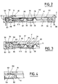
- Each contact blade 14 has a main part 24 which connects a first end portion curved 26 at a second free end 28 which allows electrical connection to a processing circuit (not shown).
- the second free end 28 is connected to the main part 24 by a connecting portion 30 on which is molded the plastic material constituting the support frame 10 during the production of the connector.
- each blade 14 would occupy position 26 ′ shown in dotted lines in FIG. 2 in which it projects vertically beyond the flat upper face 20 of the support frame 10.
- the elastic blades 14 are designed so as to be able to exert an elastic contact force, in a direction substantially perpendicular to the plane of the face 20, which is particularly high and can reach, for example, 0.5 Newton per point of contact on the card to memory C when the latter is in its reading position.
- the connector comprises a bar 32 for controlling the position of the curved end portions of contact 26 of the blades 14.
- the bar 32 is a cross bar of T-shaped section (see FIGS. 2 and 3) which extends in a direction perpendicular to the direction of introduction I of the card.
- Each of the opposite branches 34 of the T-shaped bar is capable of cooperating by its underside with a beak-shaped end 36 which extends the curved end portion 26 of each contact blade 14 in a direction substantially confused with that of the main portions 24.
- the control bar 32 connects two parallel longitudinal beams 38 together so as to constitute a control lever 40 for the movements of the control bar 32.
- Each of the side members 38 comprises a pivot 42 which extends laterally outwards and which is received in a corresponding housing 44 of the support frame 10 in which it is fitted elastically and which forms an articulation bearing to define the axis of tilting XX of the control lever 40.
- the total number of contacts on the card is less than or equal to sixteen and the frame shown in FIG. 1 corresponds to this maximum number of 16.
- the two longitudinal members 38 extend on either side of a group of contact blades 14 from the control bar 32 to an opposite complementary crosspiece 46 which completes the structure of the lever.
- the lever 40 is designed so as to be located entirely within the thickness of the support frame 10 delimited by its upper face 20 and its opposite flat lower face 48.
- the lever 40 normally occupies its rest position shown in Figures 1 and 3 towards which it is resiliently biased by two helical return springs 50 which are received in complementary housings 52 of the support frame 10 and which cooperate with the facing faces. screw 54 of two lateral end tabs 56 which extend laterally from the side members 38 in the end zone of the cross member 46.
- control bar 32 occupies a low position in which the arms 34 are in abutment against the spouts 36 of the blades 14 so as to cause the curved end portions 26 to disappear beyond the upper face.
- a projecting surface 60 forming a cam for controlling the pivoting movements of the lever 40 about its axis XX and so from the command bar 32.
- the cam surface 60 is inclined and is designed to cooperate with the front transverse edge 16 of the card when the latter is introduced into the slot F.
- the side tab 56 of the control lever 40 extends laterally beyond the area of the spring 50 to form a control tab 62 of the triggering of an electric switch 64 for detecting the limit switch for inserting card C.
- the switch 64 can be of any known type and in particular a waterproof "micro-switch" of rectangular parallelepiped shape arranged flat in a complementary housing 66 formed in the support frame 10.
- the actuator (not shown) of the switch 64 is controlled by the control tab 62 on the underside of which can be provided a pad 68 forming trigger button.
- the blades 14 also rise towards the card C under the effect of their own elasticity so that their curved end portions 26 come into contact with the corresponding lower face of the card 16.
- the front end of the card 16 bears on the abutment surface 58, the springs 50 having the effect of ensuring a slight pinching of the card between the surface 58 and the underside of the cover 18 to ensure good retention in the axial position.
- the curved contact portions 26 therefore come "to land” on the contact pads of the card practically only when the latter is in the reading position, the length of the friction stroke thus being particularly short, of the order of approximately 1 mm, this reduced stroke also promoting "self-cleaning" of the contacts.
- the geometry of the cam-shaped ramp 60 which controls the tilting of the lever 40 is designed so that the force for inserting the card into the connector is substantially constant between the start of the attack phase of the cam 60 by the front edge of the card and the end of the insertion of the card limited by a mechanical stop arranged either on the support frame 10, or at the end of the spar 38.
Landscapes
- Engineering & Computer Science (AREA)
- Artificial Intelligence (AREA)
- Computer Vision & Pattern Recognition (AREA)
- Physics & Mathematics (AREA)
- General Physics & Mathematics (AREA)
- Theoretical Computer Science (AREA)
- Coupling Device And Connection With Printed Circuit (AREA)
- Details Of Connecting Devices For Male And Female Coupling (AREA)
Applications Claiming Priority (2)
| Application Number | Priority Date | Filing Date | Title |
|---|---|---|---|
| FR9009391A FR2665029B1 (fr) | 1990-07-23 | 1990-07-23 | Connecteur electrique pour cartes a memoire electronique. |
| FR9009391 | 1990-07-23 |
Publications (2)
| Publication Number | Publication Date |
|---|---|
| EP0468828A1 true EP0468828A1 (de) | 1992-01-29 |
| EP0468828B1 EP0468828B1 (de) | 1994-10-12 |
Family
ID=9399006
Family Applications (1)
| Application Number | Title | Priority Date | Filing Date |
|---|---|---|---|
| EP91401618A Expired - Lifetime EP0468828B1 (de) | 1990-07-23 | 1991-06-17 | Elektrischer Verbinder für elektronische Speicherkarten |
Country Status (4)
| Country | Link |
|---|---|
| EP (1) | EP0468828B1 (de) |
| DE (1) | DE69104571T2 (de) |
| FR (1) | FR2665029B1 (de) |
| HK (1) | HK152096A (de) |
Cited By (15)
| Publication number | Priority date | Publication date | Assignee | Title |
|---|---|---|---|---|
| EP0554821A1 (de) * | 1992-02-04 | 1993-08-11 | The Whitaker Corporation | Chipkartenverbinder |
| WO1995013589A1 (fr) * | 1993-11-08 | 1995-05-18 | Nicomatic | Connecteur electrique et lecteur de carte le comportant |
| DE9407499U1 (de) * | 1994-05-05 | 1995-09-07 | Itt Composants Et Instruments, Dole Cedex | Elektrisches Kontaktelement |
| WO1995024716A2 (en) * | 1994-03-09 | 1995-09-14 | Philips Electronics N.V. | Device for the exchange of information with an electronic memory card, and car radio provided with such a device |
| FR2733370A1 (fr) * | 1995-04-21 | 1996-10-25 | Itt Composants Instr | Connecteur electrique pour le raccordement du bloc d'alimentation d'un appareil faisant appel a une carte a memoire electronique pour son fonctionnement |
| US5750973A (en) * | 1996-10-31 | 1998-05-12 | The Whitaker Corporation | Card reader |
| WO1998024045A1 (en) * | 1996-11-27 | 1998-06-04 | The Whitaker Corporation | eMART CARD CONNECTOR |
| WO1998027507A2 (en) * | 1996-12-17 | 1998-06-25 | The Whitaker Corporation | Landing type smart card reader |
| FR2760112A1 (fr) * | 1997-02-26 | 1998-08-28 | Whitaker Corp | Lecteur de cartes comportant un commutateur configurable |
| EP0926616A2 (de) * | 1997-12-23 | 1999-06-30 | AMPHENOL-TUCHEL ELECTRONICS GmbH | Chipkartenleser |
| US6129570A (en) * | 1998-01-09 | 2000-10-10 | Molex Incorporated | Card receptacle assembly |
| EP1056035A1 (de) * | 1999-05-25 | 2000-11-29 | Ascom Monetel S.A. | Verbinder mit einziehbaren Kontakten |
| US6308889B1 (en) * | 1997-04-21 | 2001-10-30 | Airborn, Inc. | Smart card reader with electrostatic discharge protection |
| EP1477923A1 (de) * | 2003-05-12 | 2004-11-17 | ddm hopt + schuler GmbH & Co. KG. | Kartenleser mit absenkbarem Kontaktträger |
| EP1816582A1 (de) * | 2006-02-02 | 2007-08-08 | Tyco Electronics Nederland B.V. | Lese-/Schreibvorrichtung für eine Chipkarte, Herstellungsverfahren dafür und Kontaktierverfahren für eine Chipkarte |
Citations (2)
| Publication number | Priority date | Publication date | Assignee | Title |
|---|---|---|---|---|
| EP0274684A1 (de) * | 1986-12-12 | 1988-07-20 | Omron Tateisi Electronics Co. | Chipkartenleser |
| DE8907699U1 (de) * | 1989-06-23 | 1989-08-24 | Siemens AG, 1000 Berlin und 8000 München | Kartenleser |
Family Cites Families (1)
| Publication number | Priority date | Publication date | Assignee | Title |
|---|---|---|---|---|
| FR2640780A1 (fr) * | 1988-12-20 | 1990-06-22 | Cit Alcatel | Lecteur de carte a puce |
-
1990
- 1990-07-23 FR FR9009391A patent/FR2665029B1/fr not_active Expired - Fee Related
-
1991
- 1991-06-17 EP EP91401618A patent/EP0468828B1/de not_active Expired - Lifetime
- 1991-06-17 DE DE69104571T patent/DE69104571T2/de not_active Expired - Fee Related
-
1996
- 1996-08-08 HK HK152096A patent/HK152096A/xx not_active IP Right Cessation
Patent Citations (2)
| Publication number | Priority date | Publication date | Assignee | Title |
|---|---|---|---|---|
| EP0274684A1 (de) * | 1986-12-12 | 1988-07-20 | Omron Tateisi Electronics Co. | Chipkartenleser |
| DE8907699U1 (de) * | 1989-06-23 | 1989-08-24 | Siemens AG, 1000 Berlin und 8000 München | Kartenleser |
Cited By (22)
| Publication number | Priority date | Publication date | Assignee | Title |
|---|---|---|---|---|
| EP0554821A1 (de) * | 1992-02-04 | 1993-08-11 | The Whitaker Corporation | Chipkartenverbinder |
| WO1995013589A1 (fr) * | 1993-11-08 | 1995-05-18 | Nicomatic | Connecteur electrique et lecteur de carte le comportant |
| FR2712430A1 (fr) * | 1993-11-08 | 1995-05-19 | Nicomatic | Connecteur électrique et lecteur de carte le comportant. |
| WO1995024716A2 (en) * | 1994-03-09 | 1995-09-14 | Philips Electronics N.V. | Device for the exchange of information with an electronic memory card, and car radio provided with such a device |
| WO1995024716A3 (en) * | 1994-03-09 | 1995-11-02 | Philips Electronics Nv | Device for the exchange of information with an electronic memory card, and car radio provided with such a device |
| DE9407499U1 (de) * | 1994-05-05 | 1995-09-07 | Itt Composants Et Instruments, Dole Cedex | Elektrisches Kontaktelement |
| US5527192A (en) * | 1994-05-05 | 1996-06-18 | Itt Corporation | Card connector contact element |
| FR2733370A1 (fr) * | 1995-04-21 | 1996-10-25 | Itt Composants Instr | Connecteur electrique pour le raccordement du bloc d'alimentation d'un appareil faisant appel a une carte a memoire electronique pour son fonctionnement |
| US5750973A (en) * | 1996-10-31 | 1998-05-12 | The Whitaker Corporation | Card reader |
| WO1998024045A1 (en) * | 1996-11-27 | 1998-06-04 | The Whitaker Corporation | eMART CARD CONNECTOR |
| WO1998027507A2 (en) * | 1996-12-17 | 1998-06-25 | The Whitaker Corporation | Landing type smart card reader |
| WO1998027507A3 (en) * | 1996-12-17 | 1998-11-26 | Whitaker Corp | Landing type smart card reader |
| FR2760112A1 (fr) * | 1997-02-26 | 1998-08-28 | Whitaker Corp | Lecteur de cartes comportant un commutateur configurable |
| US6308889B1 (en) * | 1997-04-21 | 2001-10-30 | Airborn, Inc. | Smart card reader with electrostatic discharge protection |
| EP0926616A2 (de) * | 1997-12-23 | 1999-06-30 | AMPHENOL-TUCHEL ELECTRONICS GmbH | Chipkartenleser |
| EP0926616A3 (de) * | 1997-12-23 | 2001-10-24 | AMPHENOL-TUCHEL ELECTRONICS GmbH | Chipkartenleser |
| US6402036B1 (en) | 1997-12-23 | 2002-06-11 | Amphenol-Tuchel Electronics Gmbh | Smart card reader |
| US6129570A (en) * | 1998-01-09 | 2000-10-10 | Molex Incorporated | Card receptacle assembly |
| EP1056035A1 (de) * | 1999-05-25 | 2000-11-29 | Ascom Monetel S.A. | Verbinder mit einziehbaren Kontakten |
| WO2000072229A1 (fr) * | 1999-05-25 | 2000-11-30 | Ascom Monetel S.A. | Connecteur a atterrissage |
| EP1477923A1 (de) * | 2003-05-12 | 2004-11-17 | ddm hopt + schuler GmbH & Co. KG. | Kartenleser mit absenkbarem Kontaktträger |
| EP1816582A1 (de) * | 2006-02-02 | 2007-08-08 | Tyco Electronics Nederland B.V. | Lese-/Schreibvorrichtung für eine Chipkarte, Herstellungsverfahren dafür und Kontaktierverfahren für eine Chipkarte |
Also Published As
| Publication number | Publication date |
|---|---|
| HK152096A (en) | 1996-08-16 |
| EP0468828B1 (de) | 1994-10-12 |
| FR2665029A1 (fr) | 1992-01-24 |
| DE69104571D1 (de) | 1994-11-17 |
| DE69104571T2 (de) | 1995-04-06 |
| FR2665029B1 (fr) | 1992-11-06 |
Similar Documents
| Publication | Publication Date | Title |
|---|---|---|
| EP0468828B1 (de) | Elektrischer Verbinder für elektronische Speicherkarten | |
| EP0348929B1 (de) | Chipkartenabtaster | |
| EP0860904B1 (de) | Verbinder für IC-Karte und damit ausgerüstetes Gehäuse | |
| EP0515897B1 (de) | Kontaktgeber für Karten mit Schaltkreis | |
| EP0316699B2 (de) | Kontaktrahmen für IC-Kartenleser mit Endkontakt | |
| EP0316700B1 (de) | Kontaktrahmen für I.S.-Kartenleser | |
| EP0510599B1 (de) | Chipkartenabtaster | |
| EP0376087B1 (de) | Chipkartenabtaster | |
| CA2105696A1 (fr) | Connecteur electrique pour carte a microcircuit | |
| EP0474519B1 (de) | Steckverbinder für elektrische Speicherkarten | |
| EP0766875B1 (de) | Elektrischer verbinder insbesondere für den anschluss einer elektronischen speicherkarte | |
| FR2773244A1 (fr) | Commutateur de detection de la presence d'une carte a memoire electronique dans un dispositif de lecture-ecriture | |
| EP0981798B1 (de) | Verbinder mit einziehbaren kontakten zum verbinden einer mikroschaltungskarte | |
| FR2793921A1 (fr) | Ensemble compact pour le raccordement d'une carte a circuit(s) integre(s) comportant des moyens d'ejection de la carte | |
| EP1382001A1 (de) | Elektrischer verbinder für eine karte | |
| FR2779254A1 (fr) | Connecteur pour le raccordement d'une carte a circuit(s) integre(s) comportant des moyens d'ejection automatique de la carte | |
| EP0209433B1 (de) | Kontaktträger, insbesondere für Schutzschalter | |
| EP0711439B1 (de) | Schalter zur erkennung der anwesenheit einer elektronischen speicherkarte in einem karten-leser/schreiber | |
| FR2844642A1 (fr) | Connecteur electrique pour une carte a memoire electronique a grande capacite de stockage | |
| FR2553569A3 (fr) | Commutateur electrique a action rapide | |
| EP0656597A1 (de) | Kartenkontaktrahmen und -verbinder | |
| FR2658364A1 (fr) | Connecteur electrique pour cartes a memoire electronique. | |
| CH645487A5 (fr) | Commutateur capacitif de touche. | |
| FR2713406A1 (fr) | Cadre de contact et connecteur pour carte. | |
| WO1995013589A1 (fr) | Connecteur electrique et lecteur de carte le comportant |
Legal Events
| Date | Code | Title | Description |
|---|---|---|---|
| PUAI | Public reference made under article 153(3) epc to a published international application that has entered the european phase |
Free format text: ORIGINAL CODE: 0009012 |
|
| AK | Designated contracting states |
Kind code of ref document: A1 Designated state(s): DE FR GB IT |
|
| 17P | Request for examination filed |
Effective date: 19920529 |
|
| 17Q | First examination report despatched |
Effective date: 19930712 |
|
| GRAA | (expected) grant |
Free format text: ORIGINAL CODE: 0009210 |
|
| STAA | Information on the status of an ep patent application or granted ep patent |
Free format text: STATUS: THE PATENT HAS BEEN GRANTED |
|
| AK | Designated contracting states |
Kind code of ref document: B1 Designated state(s): DE FR GB IT |
|
| REF | Corresponds to: |
Ref document number: 69104571 Country of ref document: DE Date of ref document: 19941117 |
|
| GBT | Gb: translation of ep patent filed (gb section 77(6)(a)/1977) |
Effective date: 19941103 |
|
| ITF | It: translation for a ep patent filed | ||
| PLBE | No opposition filed within time limit |
Free format text: ORIGINAL CODE: 0009261 |
|
| 26N | No opposition filed | ||
| REG | Reference to a national code |
Ref country code: GB Ref legal event code: IF02 |
|
| PGFP | Annual fee paid to national office [announced via postgrant information from national office to epo] |
Ref country code: GB Payment date: 20050608 Year of fee payment: 15 |
|
| PGFP | Annual fee paid to national office [announced via postgrant information from national office to epo] |
Ref country code: FR Payment date: 20050617 Year of fee payment: 15 |
|
| PGFP | Annual fee paid to national office [announced via postgrant information from national office to epo] |
Ref country code: DE Payment date: 20050801 Year of fee payment: 15 |
|
| PG25 | Lapsed in a contracting state [announced via postgrant information from national office to epo] |
Ref country code: GB Free format text: LAPSE BECAUSE OF NON-PAYMENT OF DUE FEES Effective date: 20060617 |
|
| PGFP | Annual fee paid to national office [announced via postgrant information from national office to epo] |
Ref country code: IT Payment date: 20060630 Year of fee payment: 16 |
|
| PG25 | Lapsed in a contracting state [announced via postgrant information from national office to epo] |
Ref country code: DE Free format text: LAPSE BECAUSE OF NON-PAYMENT OF DUE FEES Effective date: 20070103 |
|
| GBPC | Gb: european patent ceased through non-payment of renewal fee |
Effective date: 20060617 |
|
| REG | Reference to a national code |
Ref country code: FR Ref legal event code: ST Effective date: 20070228 |
|
| PG25 | Lapsed in a contracting state [announced via postgrant information from national office to epo] |
Ref country code: FR Free format text: LAPSE BECAUSE OF NON-PAYMENT OF DUE FEES Effective date: 20060630 |
|
| PG25 | Lapsed in a contracting state [announced via postgrant information from national office to epo] |
Ref country code: IT Free format text: LAPSE BECAUSE OF NON-PAYMENT OF DUE FEES Effective date: 20070617 |