EP0468828A1 - Electrical connector for electronic memory cards - Google Patents
Electrical connector for electronic memory cards Download PDFInfo
- Publication number
- EP0468828A1 EP0468828A1 EP91401618A EP91401618A EP0468828A1 EP 0468828 A1 EP0468828 A1 EP 0468828A1 EP 91401618 A EP91401618 A EP 91401618A EP 91401618 A EP91401618 A EP 91401618A EP 0468828 A1 EP0468828 A1 EP 0468828A1
- Authority
- EP
- European Patent Office
- Prior art keywords
- card
- lever
- control
- connector according
- bar
- Prior art date
- Legal status (The legal status is an assumption and is not a legal conclusion. Google has not performed a legal analysis and makes no representation as to the accuracy of the status listed.)
- Granted
Links
Images

Classifications
-
- G—PHYSICS
- G06—COMPUTING; CALCULATING OR COUNTING
- G06K—GRAPHICAL DATA READING; PRESENTATION OF DATA; RECORD CARRIERS; HANDLING RECORD CARRIERS
- G06K7/00—Methods or arrangements for sensing record carriers, e.g. for reading patterns
- G06K7/0013—Methods or arrangements for sensing record carriers, e.g. for reading patterns by galvanic contacts, e.g. card connectors for ISO-7816 compliant smart cards or memory cards, e.g. SD card readers
- G06K7/0056—Methods or arrangements for sensing record carriers, e.g. for reading patterns by galvanic contacts, e.g. card connectors for ISO-7816 compliant smart cards or memory cards, e.g. SD card readers housing of the card connector
- G06K7/0069—Methods or arrangements for sensing record carriers, e.g. for reading patterns by galvanic contacts, e.g. card connectors for ISO-7816 compliant smart cards or memory cards, e.g. SD card readers housing of the card connector including means for detecting correct insertion of the card, e.g. end detection switches notifying that the card has been inserted completely and correctly
-
- G—PHYSICS
- G06—COMPUTING; CALCULATING OR COUNTING
- G06K—GRAPHICAL DATA READING; PRESENTATION OF DATA; RECORD CARRIERS; HANDLING RECORD CARRIERS
- G06K7/00—Methods or arrangements for sensing record carriers, e.g. for reading patterns
- G06K7/0013—Methods or arrangements for sensing record carriers, e.g. for reading patterns by galvanic contacts, e.g. card connectors for ISO-7816 compliant smart cards or memory cards, e.g. SD card readers
- G06K7/0021—Methods or arrangements for sensing record carriers, e.g. for reading patterns by galvanic contacts, e.g. card connectors for ISO-7816 compliant smart cards or memory cards, e.g. SD card readers for reading/sensing record carriers having surface contacts
- G06K7/0026—Methods or arrangements for sensing record carriers, e.g. for reading patterns by galvanic contacts, e.g. card connectors for ISO-7816 compliant smart cards or memory cards, e.g. SD card readers for reading/sensing record carriers having surface contacts the galvanic contacts of the connector adapted for landing on the contacts of the card upon card insertion
-
- H—ELECTRICITY
- H01—ELECTRIC ELEMENTS
- H01R—ELECTRICALLY-CONDUCTIVE CONNECTIONS; STRUCTURAL ASSOCIATIONS OF A PLURALITY OF MUTUALLY-INSULATED ELECTRICAL CONNECTING ELEMENTS; COUPLING DEVICES; CURRENT COLLECTORS
- H01R12/00—Structural associations of a plurality of mutually-insulated electrical connecting elements, specially adapted for printed circuits, e.g. printed circuit boards [PCB], flat or ribbon cables, or like generally planar structures, e.g. terminal strips, terminal blocks; Coupling devices specially adapted for printed circuits, flat or ribbon cables, or like generally planar structures; Terminals specially adapted for contact with, or insertion into, printed circuits, flat or ribbon cables, or like generally planar structures
- H01R12/70—Coupling devices
- H01R12/82—Coupling devices connected with low or zero insertion force
Definitions
- the present invention relates to an electrical connector for electronic memory cards of the type comprising on one of its main faces a plurality of electrical contact pads aligned parallel to the direction of insertion of the card in a read-write device and a transverse edge.
- the connector anterior perpendicular to the direction of introduction of the card, the connector comprising a support frame having first and second parallel flat faces and a plurality of electrical conductors in the form of elastically deformable blades extending parallel to the direction of introduction of the card, each contact blade comprising a curved end portion normally projecting beyond the first planar face on which the card slides to be in contact with one of the areas of the card when the latter is in the position of reading, each contact blade extending parallel to the direction of card insertion.
- the curved end portions of the contact blades When the card is inserted into the connector, the curved end portions of the contact blades first cooperate with the anterior edge of the card which causes its elastic deflection from their normal position projecting beyond the sliding of the card. The continuation of the insertion path of the card until it reaches its final reading position, results in a prolonged friction of the convex convex zones of the end portions of the contact blades on the face opposite the map.
- the invention provides an electrical connector of the type mentioned above, characterized in that it comprises a bar for controlling the position of the curved end portions of the contact blades which is mounted movable relative to at the frame between a first rest position in which the contact end portions are erased below the first planar face of the frame and a reading position in which the contact end portions project beyond the plane of the first face, and means for controlling the movements of the control bar as a function of the position of the card relative to the frame.
- the electrical connector comprises a support frame 10 of generally rectangular shape which includes a substantially rectangular opening 12 in which electrical conductors are arranged in the form of deformable elastic blades 14 which extend parallel to the insertion direction I of a card to electronic memory C, the silhouette of which has been shown in dashed lines in FIG. 1.
- a slot F for inserting the card C is partially delimited in the upper face 20 of the support frame 10.
- the slot F is delimited laterally by two guide portions 22 and is completed by a closing cover 18 shown in FIGS. 2 to 4.
- Each contact blade 14 has a main part 24 which connects a first end portion curved 26 at a second free end 28 which allows electrical connection to a processing circuit (not shown).
- the second free end 28 is connected to the main part 24 by a connecting portion 30 on which is molded the plastic material constituting the support frame 10 during the production of the connector.
- each blade 14 would occupy position 26 ′ shown in dotted lines in FIG. 2 in which it projects vertically beyond the flat upper face 20 of the support frame 10.
- the elastic blades 14 are designed so as to be able to exert an elastic contact force, in a direction substantially perpendicular to the plane of the face 20, which is particularly high and can reach, for example, 0.5 Newton per point of contact on the card to memory C when the latter is in its reading position.
- the connector comprises a bar 32 for controlling the position of the curved end portions of contact 26 of the blades 14.
- the bar 32 is a cross bar of T-shaped section (see FIGS. 2 and 3) which extends in a direction perpendicular to the direction of introduction I of the card.
- Each of the opposite branches 34 of the T-shaped bar is capable of cooperating by its underside with a beak-shaped end 36 which extends the curved end portion 26 of each contact blade 14 in a direction substantially confused with that of the main portions 24.
- the control bar 32 connects two parallel longitudinal beams 38 together so as to constitute a control lever 40 for the movements of the control bar 32.
- Each of the side members 38 comprises a pivot 42 which extends laterally outwards and which is received in a corresponding housing 44 of the support frame 10 in which it is fitted elastically and which forms an articulation bearing to define the axis of tilting XX of the control lever 40.
- the total number of contacts on the card is less than or equal to sixteen and the frame shown in FIG. 1 corresponds to this maximum number of 16.
- the two longitudinal members 38 extend on either side of a group of contact blades 14 from the control bar 32 to an opposite complementary crosspiece 46 which completes the structure of the lever.
- the lever 40 is designed so as to be located entirely within the thickness of the support frame 10 delimited by its upper face 20 and its opposite flat lower face 48.
- the lever 40 normally occupies its rest position shown in Figures 1 and 3 towards which it is resiliently biased by two helical return springs 50 which are received in complementary housings 52 of the support frame 10 and which cooperate with the facing faces. screw 54 of two lateral end tabs 56 which extend laterally from the side members 38 in the end zone of the cross member 46.
- control bar 32 occupies a low position in which the arms 34 are in abutment against the spouts 36 of the blades 14 so as to cause the curved end portions 26 to disappear beyond the upper face.
- a projecting surface 60 forming a cam for controlling the pivoting movements of the lever 40 about its axis XX and so from the command bar 32.
- the cam surface 60 is inclined and is designed to cooperate with the front transverse edge 16 of the card when the latter is introduced into the slot F.
- the side tab 56 of the control lever 40 extends laterally beyond the area of the spring 50 to form a control tab 62 of the triggering of an electric switch 64 for detecting the limit switch for inserting card C.
- the switch 64 can be of any known type and in particular a waterproof "micro-switch" of rectangular parallelepiped shape arranged flat in a complementary housing 66 formed in the support frame 10.
- the actuator (not shown) of the switch 64 is controlled by the control tab 62 on the underside of which can be provided a pad 68 forming trigger button.
- the blades 14 also rise towards the card C under the effect of their own elasticity so that their curved end portions 26 come into contact with the corresponding lower face of the card 16.
- the front end of the card 16 bears on the abutment surface 58, the springs 50 having the effect of ensuring a slight pinching of the card between the surface 58 and the underside of the cover 18 to ensure good retention in the axial position.
- the curved contact portions 26 therefore come "to land” on the contact pads of the card practically only when the latter is in the reading position, the length of the friction stroke thus being particularly short, of the order of approximately 1 mm, this reduced stroke also promoting "self-cleaning" of the contacts.
- the geometry of the cam-shaped ramp 60 which controls the tilting of the lever 40 is designed so that the force for inserting the card into the connector is substantially constant between the start of the attack phase of the cam 60 by the front edge of the card and the end of the insertion of the card limited by a mechanical stop arranged either on the support frame 10, or at the end of the spar 38.
Abstract
Description
La présente invention concerne un connecteur électrique pour cartes à mémoire électronique du type comportant sur une de ses faces principales une pluralité de plages de contact électrique alignées parallèlement à la direction d'introduction de la carte dans un dispositif de lecture-écriture et un bord transversal antérieur perpendiculaire à la direction d'introduction de la carte, le connecteur comportant un cadre support présentant une première et une deuxième faces planes parallèles et une pluralité de conducteurs électriques en forme de lames déformables élastiquement s'étendant parallèlement à la direction d'introduction de la carte, chaque lame de contact comprenant une portion d'extrémité incurvée faisant normalement saillie au-delà de la première face plane sur laquelle coulisse la carte pour être en contact avec l'une des plages de la carte lorsque cette dernière est en position de lecture, chaque lame de contact s'étendant parallèlement à la direction d'introduction de la carte.The present invention relates to an electrical connector for electronic memory cards of the type comprising on one of its main faces a plurality of electrical contact pads aligned parallel to the direction of insertion of the card in a read-write device and a transverse edge. anterior perpendicular to the direction of introduction of the card, the connector comprising a support frame having first and second parallel flat faces and a plurality of electrical conductors in the form of elastically deformable blades extending parallel to the direction of introduction of the card, each contact blade comprising a curved end portion normally projecting beyond the first planar face on which the card slides to be in contact with one of the areas of the card when the latter is in the position of reading, each contact blade extending parallel to the direction of card insertion.
Un connecteur électrique de ce type est par exemple décrit dans la demande de brevet français n° 88 13988 du 26 octobre 1988.An electrical connector of this type is for example described in French patent application No. 88 13988 of October 26, 1988.
Lors de l'introduction de la carte dans le connecteur, les portions d'extrémité incurvées des lames de contact coopèrent d'abord avec le bord antérieur de la carte qui en provoque la déflection élastique depuis leur position normale en saillie au-delà de la phase de coulissement de la carte. La suite de la course d'introduction de la carte jusqu'à ce qu'elle atteigne sa position finale de lecture, se traduit par un frottement prolongé des zones convexes bombées des portions d'extrémité des lames de contact sur la face en regard de la carte.When the card is inserted into the connector, the curved end portions of the contact blades first cooperate with the anterior edge of the card which causes its elastic deflection from their normal position projecting beyond the sliding of the card. The continuation of the insertion path of the card until it reaches its final reading position, results in a prolonged friction of the convex convex zones of the end portions of the contact blades on the face opposite the map.
Ces chocs et frottements répétés lors de chaque introduction et de chaque extraction d'une carte provoquent très rapidement une usure de la portion d'extrémité incurvée des lames de contact, la qualité de la connexion établie entre la carte et le dispositif de lecture-écriture s'en trouvant rapidement affecté, notamment du fait de la disparition très rapide du revêtement de dorure qui est généralement prévu sur ces portions d'extrémité.These repeated shocks and rubs during each insertion and each extraction of a card very quickly cause wear of the curved end portion of the contact blades, the quality of the connection established between the card and the read-write device being quickly affected, in particular due to the very rapid disappearance of the coating gilding which is generally provided on these end portions.
Afin de remédier à cet inconvénient, l'invention propose un connecteur électrique du type mentionné plus haut, caractérisé en ce qu'il comporte une barre de commande de la position des portions d'extrémité incurvées des lames de contact qui est montée mobile par rapport au cadre entre une première position de repos dans laquelle les portions d'extrémité de contact sont effacées en-deçà de la première face plane du cadre et une position de lecture dans laquelle les portions d'extrémité de contact font saillie au-delà du plan de la première face, et des moyens de commande des déplacements de la barre de commande en fonction de la position de la carte par rapport au cadre.In order to remedy this drawback, the invention provides an electrical connector of the type mentioned above, characterized in that it comprises a bar for controlling the position of the curved end portions of the contact blades which is mounted movable relative to at the frame between a first rest position in which the contact end portions are erased below the first planar face of the frame and a reading position in which the contact end portions project beyond the plane of the first face, and means for controlling the movements of the control bar as a function of the position of the card relative to the frame.
Selon d'autres caractéristiques de l'invention :
- la barre de commande s'étend perpendiculairement à la direction des lames de contact et coopère avec les extrémités libres en forme de bec de chaque lame qui prolongent les portions d'extrémité incurvées ;
- la barre de commande est sollicitée élastiquement vers sa position normale de repos et les moyens de commande agissent à l'encontre de l'effort élastique de rappel de la barre de commande ;
- la barre de commande est reliée à un levier de commande monté pivotant sur le cadre support autour d'un axe perpendiculaire à la direction d'introduction de la carte et parallèle aux faces du cadre, une came de commande étant prévue sur le levier pour coopérer avec le bord transversal de la carte lorsque celle-ci atteint la fin de sa course d'introduction dans le dispositif de lecture-écriture et pour provoquer le pivotement du levier dans le sens correspondant au déplacement de la barre de commande vers sa position de lecture ;
- le levier de commande est un levier basculant autour d'un axe central, la barre de commande et la came de commande étant agencées chacune respectivement au voisinage de l'une des deux extrémités du levier ;
- le levier comporte deux longerons parallèles reliés entre eux par la barre de commande et qui s'étendent de part et d'autre d'un groupe de lames de contact parallèles ;
- l'axe central d'articulation comporte deux pivots qui s'étendent latéralement vers l'extérieur depuis le longeron et qui sont reçus respectivement dans deux logements correspondants du cadre formant paliers d'articulation ;
- les moyens de rappel élastique comportent au moins un ressort de compression reçu dans un logement du cadre et qui agit sur l'extrémité libre du levier au voisinage de laquelle est agencée la came de commande ;
- le levier agit sur un commutateur électrique de détection de la fin de la course d'introduction de la carte au moyen d'une patte transversale dont une face coopère avec un élément de déclenchement du commutateur électrique qui est disposée sensiblement à l'extrémité du levier au voisinage de laquelle est agencée la came de commande.
- the control bar extends perpendicular to the direction of the contact blades and cooperates with the free beak-shaped ends of each blade which extend the curved end portions;
- the control bar is urged elastically to its normal rest position and the control means act against the elastic restoring force of the control bar;
- the control bar is connected to a control lever pivotally mounted on the support frame around an axis perpendicular to the direction of introduction of the card and parallel to the faces of the frame, a control cam being provided on the lever to cooperate with the transverse edge of the card when the latter reaches the end of its path of insertion into the read-write device and to cause the lever to pivot in the direction corresponding to the movement of the control bar towards its read position;
- the control lever is a lever rocking about a central axis, the control bar and the control cam being each arranged respectively in the vicinity of one of the two ends of the lever;
- the lever comprises two parallel beams connected together by the control bar and which extend on either side of a group of parallel contact blades;
- the central axis of articulation comprises two pivots which extend laterally outwards from the spar and which are respectively received in two corresponding housings of the frame forming articulation bearings;
- the elastic return means comprise at least one compression spring received in a housing of the frame and which acts on the free end of the lever in the vicinity of which the control cam is arranged;
- the lever acts on an electrical switch for detecting the end of the card insertion stroke by means of a transverse tab, one face of which cooperates with an element for triggering the electrical switch which is arranged substantially at the end of the lever in the vicinity of which the control cam is arranged.
D'autres caractéristiques et avantages de l'invention apparaîtront à la lecture de la description détaillée qui va suivre pour la compréhension de laquelle on se reportera aux dessins annexés dans lesquels :
- La figure 1 est une vue de dessus d'un connecteur électrique réalisé conformément aux enseignements de l'invention et qui est représenté sans son couvercle ;
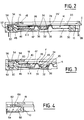
- la figure 2 est une vue en section selon la ligne 2-2 de la figure 1, le connecteur étant représenté avec une carte introduite en position de lecture ;
- la figure 3 est une vue partielle similaire à celle de la figure 2 représentant le connecteur sans carte ; et
- la figure 4 est une vue de détail en section selon la ligne 4-4 de la figure 1.
- Figure 1 is a top view of an electrical connector made in accordance with the teachings of the invention and which is shown without its cover;
- Figure 2 is a sectional view along line 2-2 of Figure 1, the connector being shown with a card inserted in the reading position;
- Figure 3 is a partial view similar to that of Figure 2 showing the connector without card; and
- Figure 4 is a detail view in section along line 4-4 of Figure 1.
La conception générale du connecteur électrique dont les principaux composants sont représentés sur les figures correspond à celle de celui décrit et représenté dans la demande de brevet français n° 88 13988 au contenu de laquelle on pourra se reporter pour une description détaillée de sa conception, de sa structure et de son procédé de réalisation.The general design of the electrical connector, the main components of which are shown in the figures, corresponds to that of that described and represented in French patent application No. 88 13988, the content of which may be referred to for a detailed description of its design, its structure and its production process.
Le connecteur électrique comprend un cadre support 10 de forme générale rectangulaire qui comprend une ouverture sensiblement rectangulaire 12 dans laquelle sont agencés des conducteurs électriques en forme de lames élastiques déformables 14 qui s'étendent parallèlement à la direction d'introduction I d'une carte à mémoire électronique C dont on a représenté la silhouette en traits mixtes à la figure 1.The electrical connector comprises a
Une fente F d'introduction de la carte C est délimitée partiellement dans la face supérieure 20 du cadre support 10.A slot F for inserting the card C is partially delimited in the
La fente F est délimitée latéralement par deux portions de guidage 22 et est complétée par un couvercle de fermeture 18 représenté aux figures 2 à 4.The slot F is delimited laterally by two
Chaque lame de contact 14 comporte une partie principale 24 qui relie une première portion d'extrémité incurvée 26 à une seconde extrémité libre 28 qui permet le raccordement électrique à un circuit de traitement (non représenté).Each
La seconde extrémité libre 28 est reliée à la partie principale 24 par une portion de liaison 30 sur laquelle est surmoulé le matériau plastique constitutif du cadre support 10 lors de la réalisation du connecteur.The second
En l'absence de cartes et s'il n'était pas prévu une barre de commande selon les enseignements de l'invention, l'extrémité incurvée 26 de chaque lame 14 occuperait la position 26′ représentée en pointillés à la figure 2 dans laquelle elle fait saillie verticalement au-delà de la face supérieure plane 20 du cadre support 10.In the absence of cards and if there was not provided a control bar according to the teachings of the invention, the
Les lames élastiques 14 sont conçues de façon à pouvoir exercer un effort élastique de contact, selon une direction sensiblement perpendiculaire au plan de la face 20, qui soit particulièrement élevé et pouvant atteindre par exemple 0,5 Newton par point de contact sur la carte à mémoire C lorsque cette dernière est dans sa position de lecture.The
Conformément à l'invention, le connecteur comporte une barre 32 de commande de la position des portions d'extrémité incurvées de contact 26 des lames 14.According to the invention, the connector comprises a
La barre 32 est une barre transversale de section en forme de T (voir figures 2 et 3) qui s'étend selon une direction perpendiculaire à la direction d'introduction I de la carte.The
Chacune des branches opposées 34 de la barre en forme de T est susceptible de coopérer par sa face inférieure avec une extrémité en forme de bec 36 qui prolonge la portion d'extrémité incurvée 26 de chaque lame de contact 14 selon une direction sensiblement confondue avec celle des portions principales 24.Each of the
La barre de commande 32 relie entre eux deux longerons longitudinaux parallèles 38 de manière à constituer un levier de commande 40 des déplacements de la barre de commande 32.The
Chacun des longerons 38 comporte un pivot 42 qui s'étend latéralement vers l'extérieur et qui est reçu dans un logement correspondant 44 du cadre support 10 dans lequel il est emboîté élastiquement et qui forme un palier d'articulation pour définir l'axe de basculement X-X du levier de commande 40.Each of the
Conformément aux normes en vigueur au moment de l'invention, le nombre total de contacts sur la carte est inférieur ou égal à seize et le cadre représenté à la figure 1 correspond à ce nombre maximal de 16.In accordance with the standards in force at the time of the invention, the total number of contacts on the card is less than or equal to sixteen and the frame shown in FIG. 1 corresponds to this maximum number of 16.
Les deux longerons 38 s'étendent de part et d'autre d'un groupe de lames de contact 14 depuis la barre de commande 32 jusqu'à une traverse complémentaire opposée 46 qui complète la structure du levier.The two
Le levier 40 est conçu de manière à être situé en totalité dans l'épaisseur du cadre support 10 délimité par sa face supérieure 20 et sa face inférieure plane opposée 48.The
Le levier 40 occupe normalement sa position de repos représentée aux figures 1 et 3 vers laquelle il est sollicité élastiquement par deux ressorts hélicoïdaux de rappel 50 qui sont reçus dans des logements complémentaires 52 du cadre support 10 et qui coopèrent avec les faces en vis-à-vis 54 de deux pattes latérales d'extrémité 56 qui s'étendent latéralement depuis les longerons 38 dans la zone d'extrémité de la traverse 46.The
Comme on peut le voir à la figure 3, l'action des ressorts 50 a pour effet de provoquer la rotation dans le sens horaire, en considérant cette figure, du levier 40 autour de son axe X-X. Cette position normale de repos est définie par une face de butée 58 formée sur le levier 40 qui coopère avec la face inférieure du couvercle 18.As can be seen in Figure 3, the action of the
Dans cette position de repos, la barre de commande 32 occupe une position basse dans laquelle les branches 34 sont en appui contre les becs 36 des lames 14 de manière à provoquer l'effacement des portions d'extrémité incurvées 26 en deçà de la face supérieure plane 20 du cadre support 10 sur laquelle vient coulisser une carte C lorsqu'elle est introduite dans le connecteur électrique.In this rest position, the
Sur la face supérieure de la traverse 46 au voisinage de l'extrémité libre de gauche du levier 40 en considérant les figures, il est prévu une surface en saillie 60 formant came de commande des déplacements en pivotement du levier 40 autour de son axe X-X et donc de la barre de commande 32.On the upper face of the
La surface de came 60 est inclinée et est prévue pour coopérer avec le bord transversal antérieur 16 de la carte lorsque celle-ci est introduite dans la fente F.The
Comme on peut le constater à la figure 1, la patte latérale 56 du levier de commande 40 se prolonge latéralement au-delà de la zone du ressort 50 pour constituer une patte de commande 62 du déclenchement d'un commutateur électrique 64 de détection de la fin de course d'introduction de la carte C.As can be seen in Figure 1, the
Le commutateur 64 peut être de tout type connu et notamment un "micro-switch" étanche de forme parallépipédique rectangle agencé à plat dans un logement complémentaire 66 formé dans le cadre support 10.The
La commande de l'organe de déclenchement (non représenté) du commutateur 64 est assurée par la patte de commande 62 sur la face inférieure de laquelle peut être prévu un plot 68 formant poussoir de déclenchement.The actuator (not shown) of the
On décrira maintenant le mode de fonctionnement du connecteur électrique en se reportant notamment aux figures 2 et 3.The mode of operation of the electrical connector will now be described with particular reference to FIGS. 2 and 3.
Lorsque le connecteur électrique est vide, l'ensemble de ses composants occupe la position représentée à la figure 3 sur laquelle on constate qu'il est possible d'introduire une carte dans la fente F sans que son bord antérieur 16 ni sa face inférieure de coulissement qui coopère avec la face supérieure 20 du cadre support 10 ne viennent rencontrer ni frotter sur les portions d'extrémité incurvées 26 des lames de contact 14. En effet ces portions 26 sont maintenues en position effacée en-deçà de la face 20 par la barre de commande 32 comme cela est illustré à la figure 3.When the electrical connector is empty, all of its components occupy the position shown in FIG. 3 in which it can be seen that it is possible to introduce a card into the slot F without its
Lorsque l'on introduit une carte C et que celle-ci arrive à proximité de sa fin de course d'introduction, son bord transversal antérieur 16 vient en contact avec la surface de came de commande 60 de manière à provoquer le basculement du levier de commande 40 autour de son axe X-X dans le sens anti-horaire en considérant la figure 3, à l'encontre de l'effort élastique de rappel qui lui est appliqué par les ressorts 50.When a card C is introduced and the card arrives near its end of insertion stroke, its front
Ce mouvement de basculement a pour effet de provoquer le déplacement de la barre de commande 32 selon une direction sensiblement verticale jusqu'à ce qu'elle vienne occuper sa position haute de lecture représentée à la figure 2 dans laquelle ses branches 34 ne coopèrent plus avec les becs 36 des lames 14.The effect of this tilting movement is to cause the
Au cours de ce pivotement, les lames 14 remontent également en direction de la carte C sous l'effet de leur élasticité propre de manière que leurs portions d'extrémité incurvées 26 viennent en contact avec la face inférieure correspondante de la carte 16.During this pivoting, the
En position de lecture telle que représentée à la figure 2. l'extrémité antérieure de la carte 16 est en appui sur la surface de butée 58, les ressorts 50 ayant pour effet d'assurer un léger pincement de la carte entre la surface 58 et la face inférieure du couvercle 18 pour en assurer un bon maintien en position axiale.In the reading position as shown in FIG. 2. the front end of the
Les portions de contact incurvées 26 ne viennent donc "atterrir" sur les plages de contact de la carte pratiquement que lorsque cette dernière est en position de lecture, la longueur de la course de frottement étant ainsi particulièrement courte, de l'ordre d'environ 1 mm, cette course réduite favorisant par ailleurs un "auto-nettoyage" des contacts.The
La géométrie de la rampe en forme de came 60 qui commande le basculement du levier 40 est conçue de manière à ce que l'effort d'insertion de la carte dans le connecteur soit sensiblement constant entre le début de la phase d'attaque de la came 60 par le bord antérieur de la carte et la fin de l'insertion de la carte limitée par une butée mécanique aménagée soit sur le cadre support 10, soit en extrémité de longeron 38.The geometry of the cam-shaped
Grâce à cette conception, il est possible de disposer le commutateur de fin de course 64 en position horizontale et de limiter ainsi l'épaisseur du connecteur tout en rendant le changement d'état du commutateur 64 conforme aux normes de sécurité d'utilisation des cartes à micro-circuit.Thanks to this design, it is possible to place the
A titre de variante non représentée, il est possible d'incorporer au levier 40 un insert métallique surmoulé en forme de plaque dont des portions pourraient constituer les pattes 56 et 62. De même les ressorts 50 pourraient être remplacés par des languettes élastiques faisant partie de l'insert de renfort.As a variant not shown, it is possible to incorporate into the lever 40 a metal insert overmolded in the form of a plate, portions of which could constitute the
Claims (11)
Applications Claiming Priority (2)
| Application Number | Priority Date | Filing Date | Title |
|---|---|---|---|
| FR9009391A FR2665029B1 (en) | 1990-07-23 | 1990-07-23 | ELECTRICAL CONNECTOR FOR ELECTRONIC MEMORY CARDS. |
| FR9009391 | 1990-07-23 |
Publications (2)
| Publication Number | Publication Date |
|---|---|
| EP0468828A1 true EP0468828A1 (en) | 1992-01-29 |
| EP0468828B1 EP0468828B1 (en) | 1994-10-12 |
Family
ID=9399006
Family Applications (1)
| Application Number | Title | Priority Date | Filing Date |
|---|---|---|---|
| EP91401618A Expired - Lifetime EP0468828B1 (en) | 1990-07-23 | 1991-06-17 | Electrical connector for electronic memory cards |
Country Status (4)
| Country | Link |
|---|---|
| EP (1) | EP0468828B1 (en) |
| DE (1) | DE69104571T2 (en) |
| FR (1) | FR2665029B1 (en) |
| HK (1) | HK152096A (en) |
Cited By (15)
| Publication number | Priority date | Publication date | Assignee | Title |
|---|---|---|---|---|
| EP0554821A1 (en) * | 1992-02-04 | 1993-08-11 | The Whitaker Corporation | Smart card connector |
| WO1995013589A1 (en) * | 1993-11-08 | 1995-05-18 | Nicomatic | Electric connector and card reader comprising same |
| DE9407499U1 (en) * | 1994-05-05 | 1995-09-07 | Itt Composants Instr | Electrical contact element |
| WO1995024716A2 (en) * | 1994-03-09 | 1995-09-14 | Philips Electronics N.V. | Device for the exchange of information with an electronic memory card, and car radio provided with such a device |
| FR2733370A1 (en) * | 1995-04-21 | 1996-10-25 | Itt Composants Instr | Electrical connector for integrated circuit memory card |
| US5750973A (en) * | 1996-10-31 | 1998-05-12 | The Whitaker Corporation | Card reader |
| WO1998024045A1 (en) * | 1996-11-27 | 1998-06-04 | The Whitaker Corporation | eMART CARD CONNECTOR |
| WO1998027507A2 (en) * | 1996-12-17 | 1998-06-25 | The Whitaker Corporation | Landing type smart card reader |
| FR2760112A1 (en) * | 1997-02-26 | 1998-08-28 | Whitaker Corp | CARD READER COMPRISING A CONFIGURABLE SWITCH |
| EP0926616A2 (en) * | 1997-12-23 | 1999-06-30 | AMPHENOL-TUCHEL ELECTRONICS GmbH | A smart card reader |
| US6129570A (en) * | 1998-01-09 | 2000-10-10 | Molex Incorporated | Card receptacle assembly |
| EP1056035A1 (en) * | 1999-05-25 | 2000-11-29 | Ascom Monetel S.A. | Connector with landing contacts |
| US6308889B1 (en) * | 1997-04-21 | 2001-10-30 | Airborn, Inc. | Smart card reader with electrostatic discharge protection |
| EP1477923A1 (en) * | 2003-05-12 | 2004-11-17 | ddm hopt + schuler GmbH & Co. KG. | Card reader with a pivoting contact carrier |
| EP1816582A1 (en) * | 2006-02-02 | 2007-08-08 | Tyco Electronics Nederland B.V. | Smart card reading/writing device, manufacturing method thereof and method for contacting smart card |
Citations (2)
| Publication number | Priority date | Publication date | Assignee | Title |
|---|---|---|---|---|
| EP0274684A1 (en) * | 1986-12-12 | 1988-07-20 | Omron Tateisi Electronics Co. | IC card reader |
| DE8907699U1 (en) * | 1989-06-23 | 1989-08-24 | Siemens Ag, 1000 Berlin Und 8000 Muenchen, De |
Family Cites Families (1)
| Publication number | Priority date | Publication date | Assignee | Title |
|---|---|---|---|---|
| FR2640780A1 (en) * | 1988-12-20 | 1990-06-22 | Cit Alcatel | CHIP CARD READER |
-
1990
- 1990-07-23 FR FR9009391A patent/FR2665029B1/en not_active Expired - Fee Related
-
1991
- 1991-06-17 EP EP91401618A patent/EP0468828B1/en not_active Expired - Lifetime
- 1991-06-17 DE DE69104571T patent/DE69104571T2/en not_active Expired - Fee Related
-
1996
- 1996-08-08 HK HK152096A patent/HK152096A/en not_active IP Right Cessation
Patent Citations (2)
| Publication number | Priority date | Publication date | Assignee | Title |
|---|---|---|---|---|
| EP0274684A1 (en) * | 1986-12-12 | 1988-07-20 | Omron Tateisi Electronics Co. | IC card reader |
| DE8907699U1 (en) * | 1989-06-23 | 1989-08-24 | Siemens Ag, 1000 Berlin Und 8000 Muenchen, De |
Cited By (22)
| Publication number | Priority date | Publication date | Assignee | Title |
|---|---|---|---|---|
| EP0554821A1 (en) * | 1992-02-04 | 1993-08-11 | The Whitaker Corporation | Smart card connector |
| WO1995013589A1 (en) * | 1993-11-08 | 1995-05-18 | Nicomatic | Electric connector and card reader comprising same |
| FR2712430A1 (en) * | 1993-11-08 | 1995-05-19 | Nicomatic | Electrical connector and card reader with it. |
| WO1995024716A2 (en) * | 1994-03-09 | 1995-09-14 | Philips Electronics N.V. | Device for the exchange of information with an electronic memory card, and car radio provided with such a device |
| WO1995024716A3 (en) * | 1994-03-09 | 1995-11-02 | Philips Electronics Nv | Device for the exchange of information with an electronic memory card, and car radio provided with such a device |
| DE9407499U1 (en) * | 1994-05-05 | 1995-09-07 | Itt Composants Instr | Electrical contact element |
| US5527192A (en) * | 1994-05-05 | 1996-06-18 | Itt Corporation | Card connector contact element |
| FR2733370A1 (en) * | 1995-04-21 | 1996-10-25 | Itt Composants Instr | Electrical connector for integrated circuit memory card |
| US5750973A (en) * | 1996-10-31 | 1998-05-12 | The Whitaker Corporation | Card reader |
| WO1998024045A1 (en) * | 1996-11-27 | 1998-06-04 | The Whitaker Corporation | eMART CARD CONNECTOR |
| WO1998027507A2 (en) * | 1996-12-17 | 1998-06-25 | The Whitaker Corporation | Landing type smart card reader |
| WO1998027507A3 (en) * | 1996-12-17 | 1998-11-26 | Whitaker Corp | Landing type smart card reader |
| FR2760112A1 (en) * | 1997-02-26 | 1998-08-28 | Whitaker Corp | CARD READER COMPRISING A CONFIGURABLE SWITCH |
| US6308889B1 (en) * | 1997-04-21 | 2001-10-30 | Airborn, Inc. | Smart card reader with electrostatic discharge protection |
| EP0926616A2 (en) * | 1997-12-23 | 1999-06-30 | AMPHENOL-TUCHEL ELECTRONICS GmbH | A smart card reader |
| EP0926616A3 (en) * | 1997-12-23 | 2001-10-24 | AMPHENOL-TUCHEL ELECTRONICS GmbH | A smart card reader |
| US6402036B1 (en) | 1997-12-23 | 2002-06-11 | Amphenol-Tuchel Electronics Gmbh | Smart card reader |
| US6129570A (en) * | 1998-01-09 | 2000-10-10 | Molex Incorporated | Card receptacle assembly |
| EP1056035A1 (en) * | 1999-05-25 | 2000-11-29 | Ascom Monetel S.A. | Connector with landing contacts |
| WO2000072229A1 (en) * | 1999-05-25 | 2000-11-30 | Ascom Monetel S.A. | Connector with reduced contact wear |
| EP1477923A1 (en) * | 2003-05-12 | 2004-11-17 | ddm hopt + schuler GmbH & Co. KG. | Card reader with a pivoting contact carrier |
| EP1816582A1 (en) * | 2006-02-02 | 2007-08-08 | Tyco Electronics Nederland B.V. | Smart card reading/writing device, manufacturing method thereof and method for contacting smart card |
Also Published As
| Publication number | Publication date |
|---|---|
| FR2665029A1 (en) | 1992-01-24 |
| FR2665029B1 (en) | 1992-11-06 |
| DE69104571T2 (en) | 1995-04-06 |
| DE69104571D1 (en) | 1994-11-17 |
| EP0468828B1 (en) | 1994-10-12 |
| HK152096A (en) | 1996-08-16 |
Similar Documents
| Publication | Publication Date | Title |
|---|---|---|
| EP0468828B1 (en) | Electrical connector for electronic memory cards | |
| EP0348929B1 (en) | Chip card reader | |
| EP0515897B1 (en) | Circuit cards connector | |
| EP0316699B2 (en) | Contact frame for an IC card reader having a terminating contact | |
| EP0316700B1 (en) | Contact frame for an ic card reader | |
| EP0510599B1 (en) | Chip card reader | |
| EP0587497A1 (en) | Electrical connector for a microcircuit card | |
| EP0376087B1 (en) | Chip card reader | |
| WO1997039418A1 (en) | Electronic connection box for a personal computer with a smart card connector | |
| FR2803428A1 (en) | SIDE OPERATION ELECTRIC SWITCH | |
| EP0474519B1 (en) | Connector for electric memory cards | |
| EP0766875B1 (en) | Electrical connector, in particular for connecting an electronic memory card | |
| FR2773244A1 (en) | SWITCH FOR DETECTING THE PRESENCE OF AN ELECTRONIC MEMORY CARD IN A READ-WRITE DEVICE | |
| EP0981798B1 (en) | Sliding contact connector for connecting a card with microcircuits | |
| FR2793921A1 (en) | Smart card connector assembly e.g. for GSM type cellular telephone, includes hook and spring arrangement for locking carriage in operating position, where end nose of hook is inserted into locking cam in carriage | |
| FR2779254A1 (en) | CONNECTOR FOR CONNECTING A CARD WITH AN INTEGRATED CIRCUIT (S) HAVING AUTOMATIC CARD EJECTION MEANS | |
| EP0209433B1 (en) | Mobile contacts support, in particular for a protection circuit breaker | |
| EP0711439B1 (en) | Switch for detecting the presence of an electronic memory card in a read/write device | |
| FR2844642A1 (en) | High storage capacity integrated circuit card electrical connector having memory card lower face contact ends and conductor plane near crossing edge holder and having upper locking element. | |
| FR2553569A3 (en) | Snap action electrical switch | |
| EP0656597A1 (en) | Card contact frame and connector | |
| FR2713406A1 (en) | Contact frame and card connector. | |
| WO1995013589A1 (en) | Electric connector and card reader comprising same | |
| EP0438001B1 (en) | Connector insertion device | |
| FR2759184A1 (en) | Electronic connection box for microcomputer with chip card connector |
Legal Events
| Date | Code | Title | Description |
|---|---|---|---|
| PUAI | Public reference made under article 153(3) epc to a published international application that has entered the european phase |
Free format text: ORIGINAL CODE: 0009012 |
|
| AK | Designated contracting states |
Kind code of ref document: A1 Designated state(s): DE FR GB IT |
|
| 17P | Request for examination filed |
Effective date: 19920529 |
|
| 17Q | First examination report despatched |
Effective date: 19930712 |
|
| GRAA | (expected) grant |
Free format text: ORIGINAL CODE: 0009210 |
|
| STAA | Information on the status of an ep patent application or granted ep patent |
Free format text: STATUS: THE PATENT HAS BEEN GRANTED |
|
| AK | Designated contracting states |
Kind code of ref document: B1 Designated state(s): DE FR GB IT |
|
| REF | Corresponds to: |
Ref document number: 69104571 Country of ref document: DE Date of ref document: 19941117 |
|
| GBT | Gb: translation of ep patent filed (gb section 77(6)(a)/1977) |
Effective date: 19941103 |
|
| ITF | It: translation for a ep patent filed |
Owner name: BUGNION S.P.A. |
|
| PLBE | No opposition filed within time limit |
Free format text: ORIGINAL CODE: 0009261 |
|
| 26N | No opposition filed | ||
| REG | Reference to a national code |
Ref country code: GB Ref legal event code: IF02 |
|
| PGFP | Annual fee paid to national office [announced via postgrant information from national office to epo] |
Ref country code: GB Payment date: 20050608 Year of fee payment: 15 |
|
| PGFP | Annual fee paid to national office [announced via postgrant information from national office to epo] |
Ref country code: FR Payment date: 20050617 Year of fee payment: 15 |
|
| PGFP | Annual fee paid to national office [announced via postgrant information from national office to epo] |
Ref country code: DE Payment date: 20050801 Year of fee payment: 15 |
|
| PG25 | Lapsed in a contracting state [announced via postgrant information from national office to epo] |
Ref country code: GB Free format text: LAPSE BECAUSE OF NON-PAYMENT OF DUE FEES Effective date: 20060617 |
|
| PGFP | Annual fee paid to national office [announced via postgrant information from national office to epo] |
Ref country code: IT Payment date: 20060630 Year of fee payment: 16 |
|
| PG25 | Lapsed in a contracting state [announced via postgrant information from national office to epo] |
Ref country code: DE Free format text: LAPSE BECAUSE OF NON-PAYMENT OF DUE FEES Effective date: 20070103 |
|
| GBPC | Gb: european patent ceased through non-payment of renewal fee |
Effective date: 20060617 |
|
| REG | Reference to a national code |
Ref country code: FR Ref legal event code: ST Effective date: 20070228 |
|
| PG25 | Lapsed in a contracting state [announced via postgrant information from national office to epo] |
Ref country code: FR Free format text: LAPSE BECAUSE OF NON-PAYMENT OF DUE FEES Effective date: 20060630 |
|
| PG25 | Lapsed in a contracting state [announced via postgrant information from national office to epo] |
Ref country code: IT Free format text: LAPSE BECAUSE OF NON-PAYMENT OF DUE FEES Effective date: 20070617 |