EP0468614B1 - Pivotable connection for fluid operated tool - Google Patents
Pivotable connection for fluid operated tool Download PDFInfo
- Publication number
- EP0468614B1 EP0468614B1 EP91302249A EP91302249A EP0468614B1 EP 0468614 B1 EP0468614 B1 EP 0468614B1 EP 91302249 A EP91302249 A EP 91302249A EP 91302249 A EP91302249 A EP 91302249A EP 0468614 B1 EP0468614 B1 EP 0468614B1
- Authority
- EP
- European Patent Office
- Prior art keywords
- connector portion
- connector
- tool
- drive
- axis
- Prior art date
- Legal status (The legal status is an assumption and is not a legal conclusion. Google has not performed a legal analysis and makes no representation as to the accuracy of the status listed.)
- Expired - Lifetime
Links
Images
Classifications
-
- F—MECHANICAL ENGINEERING; LIGHTING; HEATING; WEAPONS; BLASTING
- F16—ENGINEERING ELEMENTS AND UNITS; GENERAL MEASURES FOR PRODUCING AND MAINTAINING EFFECTIVE FUNCTIONING OF MACHINES OR INSTALLATIONS; THERMAL INSULATION IN GENERAL
- F16L—PIPES; JOINTS OR FITTINGS FOR PIPES; SUPPORTS FOR PIPES, CABLES OR PROTECTIVE TUBING; MEANS FOR THERMAL INSULATION IN GENERAL
- F16L39/00—Joints or fittings for double-walled or multi-channel pipes or pipe assemblies
- F16L39/04—Joints or fittings for double-walled or multi-channel pipes or pipe assemblies allowing adjustment or movement
-
- B—PERFORMING OPERATIONS; TRANSPORTING
- B25—HAND TOOLS; PORTABLE POWER-DRIVEN TOOLS; MANIPULATORS
- B25B—TOOLS OR BENCH DEVICES NOT OTHERWISE PROVIDED FOR, FOR FASTENING, CONNECTING, DISENGAGING, OR HOLDING
- B25B21/00—Portable power-driven screw or nut setting or loosening tools; Attachments for drilling apparatus serving the same purpose
- B25B21/004—Portable power-driven screw or nut setting or loosening tools; Attachments for drilling apparatus serving the same purpose of the ratchet type
- B25B21/005—Portable power-driven screw or nut setting or loosening tools; Attachments for drilling apparatus serving the same purpose of the ratchet type driven by a radially acting hydraulic or pneumatic piston
-
- B—PERFORMING OPERATIONS; TRANSPORTING
- B25—HAND TOOLS; PORTABLE POWER-DRIVEN TOOLS; MANIPULATORS
- B25F—COMBINATION OR MULTI-PURPOSE TOOLS NOT OTHERWISE PROVIDED FOR; DETAILS OR COMPONENTS OF PORTABLE POWER-DRIVEN TOOLS NOT PARTICULARLY RELATED TO THE OPERATIONS PERFORMED AND NOT OTHERWISE PROVIDED FOR
- B25F5/00—Details or components of portable power-driven tools not particularly related to the operations performed and not otherwise provided for
- B25F5/005—Hydraulic driving means
-
- Y—GENERAL TAGGING OF NEW TECHNOLOGICAL DEVELOPMENTS; GENERAL TAGGING OF CROSS-SECTIONAL TECHNOLOGIES SPANNING OVER SEVERAL SECTIONS OF THE IPC; TECHNICAL SUBJECTS COVERED BY FORMER USPC CROSS-REFERENCE ART COLLECTIONS [XRACs] AND DIGESTS
- Y10—TECHNICAL SUBJECTS COVERED BY FORMER USPC
- Y10T—TECHNICAL SUBJECTS COVERED BY FORMER US CLASSIFICATION
- Y10T137/00—Fluid handling
- Y10T137/8593—Systems
- Y10T137/86268—With running joint between movable parts of system
Definitions
- the present invention relates generally to tools operated by pressurised working fluid and more particularly to hydraulically operated tools such as torque wrenches.
- Fluid pressure-operated torque tools are known and widely used for tightening or loosening threaded connectors.
- a known fluid pressure-operated torque tool has an active part which engages and turns the threaded connector, and a drive part which drives the active part under the action of a pressurised working fluid.
- the drive part is usually formed as a cylinder-piston unit which is supplied with the working fluid from a source. Since during the operation, the cylinder-piston unit performs a forward stroke and a reverse stroke, the working fluid must be supplied alternately to opposite chambers of the cylinder on opposite sides of the piston in the cylinder-piston unit.
- the cylinder is usually provided with two passages each having first ends which open into the chambers respectively on opposite sides of the piston, and second ends connected by a respective one of two hoses with a source of the working fluid.
- the connection of the second ends of the passages with the hoses is normally performed through swivel connectors and one such swivel connector is disclosed for example in my US Patent No. 4921010.
- This swivel connector has two parts which are swivelable relative to one another so as to prevent the hoses interfering one with the other during operation of the tool which very often resulted in inter-hose interference in the older tools. While the swivel connector described in the aforesaid patent is better than any previously used swivel connector, it does not completely eliminate the problem of the hoses hampering operation during manipulations with the tool.
- the present invention seeks to provide a fluid pressure-operated tool which is connected with a source of a pressurised working fluid so that it can be manipulated in any desirable manner without interference by hoses connecting the source to the tool.
- a fluid pressure-operated tool which has an active part arranged to act on a threaded connector to be tightened or loosened, a fluid pressure-operated drive part arranged to act on the active part so that the latter tightens or loosens a threaded connector and a connector for connecting the drive part with the source of working fluid, which is characterised in that the connector has a first connector portion which is mounted on one of said parts turnably about a first axis, and a second connector portion which is mounted on the first connector portion turnably about a second axis which is inclined at an angle relative to the first axis.
- a fluid pressure-operated tool in accordance with the present invention is easier to manipulate without interference by the hoses connected to a source of the working fluid on the one hand, and to the connector on the other hand.
- a hydraulic tool in accordance with the present invention has an active part which is identified with reference numeral 1 but is shown only schematically.
- the active part can be formed in a known manner as in other hydraulically operated tools and especially tool wrenches.
- it can have a rachet-pawl unit 1a with a ratchet having a hexagonal opening 1b or a formation for attaching a socket, and a pawl 1c engaging the ratchet and turnable together with a drive link as disclosed for example is US-A-4,825,730.
- the hydraulic tool further has a drive part identified as a whole with reference numeral 2 in Figure 1 and formed as a hydraulically operated cylinder-piston unit.
- the drive part 2 has a cylinder 3, a piston 4 movable in the cylinder 3 and provided with a piston rod 5 which is connected with the drive link carrying the pawl of the active part.
- the drive link together with the pawl are turned in respective directions so as to turn the ratchet with the engaging formation and correspondingly turn a threaded connector.
- the cylinder 3 of the cylinder-piston unit has two chambers formed on opposite sides of the piston 4 but the right-hand chamber is of zero volume in the arrangement shown in Figure 1.
- the cylinder 3 For displacing the piston 4 in respective directions, the cylinder 3 is provided with passages 6 and 7 which extend to the respective chambers of the cylinder and through which hydraulic liquid can be supplied from a pressurised source 8 of the working fluid. Depending on whether the pressurised working fluid is supplied through the passage 6 or through the passage 7, the piston 4 is moved in a corresponding direction and as a result, the active part is turned in a corresponding direction to tighten or loosen a threaded connector to which it is attached.
- the passages 6 and 7 are connected with the source 8 through a connector which is identified as a whole with reference numeral 9.
- the connector 9 has a first connector portion 10 and a second connector portion 11.
- the first connector portion 10 is seated on an end part 12 of the cylinder 3 which has a smaller diameter than the adjacent part of the cylinder 3.
- the first connector portion 10 thus abuts against a shoulder 13 formed at one extremity of the part 12 and is retained in this position by a retaining ring 14.
- the first connector portion 10 is rotatably arranged on the cylinder part 12 to turn about an axis A.
- the first connector portion 10 is provided with through-passages 15 and 16 having respective outlets 17 and 18 which are formed as annular grooves provided on an inner surface 19 of the connector portion 10.
- the outlets 17 and 18 of the passages 15 and 16 coincide, respectively, with inlets 20 and 21 of the passages 6 and 7 in the cylinder 3.
- the passages 15 and 16 also have respective inlet portions 22 and 23 which are each formed as an annular groove provided on an outer surface of the connector portion 10. More particularly, while the outlets 17 and 18 of the passages 15 and 16 are formed so that they open to an inner bore 24 of an annular section 25 of the connector portion 10, the inlets 22 and 23 are open on the outer surface of a cylindrical section 26 of the connector portion 10.
- the second portion 11 of the connector 9 has spaced-apart inlets 27 and 28.
- Hoses 29 and 30 (shown schematically in Figure 2) extend from the source 8 and their opposite ends are inserted into the inlets 27 and 28.
- Passages 31 and 32 extend from the inlets 27 and 28 in the second connector portion 11 and their outlets 33 and 34 coincide with the inlets 22 and 23 of the passages 15 and 16 of the first connector portion 10.
- the second connector portion 11 is arranged turnably on the cylindrical section 26 of the first connector portion 10 and is retained on the latter by a retaining ring 35 which is received in a groove 36 formed in the first connector portion 10.
- first connector portion 10 is mounted on the drive part 2 of the hydraulic tool to turn about the first axis A
- second connector portion 11 is mounted on the first connector portion 10 to turn about an axis B which extends at an angle relative to the axis A.
- the angle between the axes A and B is 90°; however, it need not be a right angle.
- the connector portion 10 is mounted on the drive part 2 or on the cylinder 3 of the drive part; however, it can also be mounted on another part of the tool.
- a plurality of sealing means e.g.
- O-rings are provided between the relatively movable parts to separate the hydraulic fluid from hose 29 and passages 31, 16 and 7 from the fluid in hose 30 and passages 32, 15 and 6 while allowing turning of connector portion 11 on the connector portion 10 and the connector portion 10 on the drive part 2.
Landscapes
- Engineering & Computer Science (AREA)
- Mechanical Engineering (AREA)
- General Engineering & Computer Science (AREA)
- Quick-Acting Or Multi-Walled Pipe Joints (AREA)
- Earth Drilling (AREA)
- Fluid-Pressure Circuits (AREA)
- Joints Allowing Movement (AREA)
Abstract
Description
- The present invention relates generally to tools operated by pressurised working fluid and more particularly to hydraulically operated tools such as torque wrenches.
- Fluid pressure-operated torque tools are known and widely used for tightening or loosening threaded connectors. A known fluid pressure-operated torque tool has an active part which engages and turns the threaded connector, and a drive part which drives the active part under the action of a pressurised working fluid. The drive part is usually formed as a cylinder-piston unit which is supplied with the working fluid from a source. Since during the operation, the cylinder-piston unit performs a forward stroke and a reverse stroke, the working fluid must be supplied alternately to opposite chambers of the cylinder on opposite sides of the piston in the cylinder-piston unit. For this purpose the cylinder is usually provided with two passages each having first ends which open into the chambers respectively on opposite sides of the piston, and second ends connected by a respective one of two hoses with a source of the working fluid. The connection of the second ends of the passages with the hoses is normally performed through swivel connectors and one such swivel connector is disclosed for example in my US Patent No. 4921010. This swivel connector has two parts which are swivelable relative to one another so as to prevent the hoses interfering one with the other during operation of the tool which very often resulted in inter-hose interference in the older tools. While the swivel connector described in the aforesaid patent is better than any previously used swivel connector, it does not completely eliminate the problem of the hoses hampering operation during manipulations with the tool.
- It is one aim of the present invention to provide a fluid pressure-operated tool which avoids the disadvantages of the prior art tools.
- More particularly, the present invention seeks to provide a fluid pressure-operated tool which is connected with a source of a pressurised working fluid so that it can be manipulated in any desirable manner without interference by hoses connecting the source to the tool.
- One feature of the present invention resides, briefly stated, in a fluid pressure-operated tool which has an active part arranged to act on a threaded connector to be tightened or loosened, a fluid pressure-operated drive part arranged to act on the active part so that the latter tightens or loosens a threaded connector and a connector for connecting the drive part with the source of working fluid, which is characterised in that the connector has a first connector portion which is mounted on one of said parts turnably about a first axis, and a second connector portion which is mounted on the first connector portion turnably about a second axis which is inclined at an angle relative to the first axis.
- A fluid pressure-operated tool in accordance with the present invention is easier to manipulate without interference by the hoses connected to a source of the working fluid on the one hand, and to the connector on the other hand.
- The invention will now be further described, by way of example, with reference to the accompanying drawing, in which:
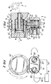
- Figure 1 is a sectional side view of part of one embodiment of hydraulic tool in accordance with the present invention; and
- Figure 2 is an end view of the hydraulic tool of Figure 1.
- A hydraulic tool in accordance with the present invention has an active part which is identified with reference numeral 1 but is shown only schematically. The active part can be formed in a known manner as in other hydraulically operated tools and especially tool wrenches. In other words, it can have a rachet-pawl unit 1a with a ratchet having a hexagonal opening 1b or a formation for attaching a socket, and a
pawl 1c engaging the ratchet and turnable together with a drive link as disclosed for example is US-A-4,825,730. The hydraulic tool further has a drive part identified as a whole with reference numeral 2 in Figure 1 and formed as a hydraulically operated cylinder-piston unit. The drive part 2 has acylinder 3, apiston 4 movable in thecylinder 3 and provided with a piston rod 5 which is connected with the drive link carrying the pawl of the active part. During the operation of the hydraulic drive unit and respective displacement of thepiston 4 in thecylinder 3, the drive link together with the pawl are turned in respective directions so as to turn the ratchet with the engaging formation and correspondingly turn a threaded connector. Thecylinder 3 of the cylinder-piston unit has two chambers formed on opposite sides of thepiston 4 but the right-hand chamber is of zero volume in the arrangement shown in Figure 1. For displacing thepiston 4 in respective directions, thecylinder 3 is provided withpassages 6 and 7 which extend to the respective chambers of the cylinder and through which hydraulic liquid can be supplied from apressurised source 8 of the working fluid. Depending on whether the pressurised working fluid is supplied through the passage 6 or through thepassage 7, thepiston 4 is moved in a corresponding direction and as a result, the active part is turned in a corresponding direction to tighten or loosen a threaded connector to which it is attached. - The
passages 6 and 7 are connected with thesource 8 through a connector which is identified as a whole with reference numeral 9. The connector 9 has afirst connector portion 10 and asecond connector portion 11. Thefirst connector portion 10 is seated on anend part 12 of thecylinder 3 which has a smaller diameter than the adjacent part of thecylinder 3. Thefirst connector portion 10 thus abuts against ashoulder 13 formed at one extremity of thepart 12 and is retained in this position by aretaining ring 14. Thefirst connector portion 10 is rotatably arranged on thecylinder part 12 to turn about an axis A. Thefirst connector portion 10 is provided with through-passages respective outlets inner surface 19 of theconnector portion 10. Theoutlets passages passages 6 and 7 in thecylinder 3. Thepassages respective inlet portions connector portion 10. More particularly, while theoutlets passages annular section 25 of theconnector portion 10, theinlets cylindrical section 26 of theconnector portion 10. - The
second portion 11 of the connector 9 has spaced-apartinlets Hoses 29 and 30 (shown schematically in Figure 2) extend from thesource 8 and their opposite ends are inserted into theinlets Passages inlets second connector portion 11 and their outlets 33 and 34 coincide with theinlets passages first connector portion 10. Thesecond connector portion 11 is arranged turnably on thecylindrical section 26 of thefirst connector portion 10 and is retained on the latter by a retainingring 35 which is received in agroove 36 formed in thefirst connector portion 10. - While the
first connector portion 10 is mounted on the drive part 2 of the hydraulic tool to turn about the first axis A, thesecond connector portion 11 is mounted on thefirst connector portion 10 to turn about an axis B which extends at an angle relative to the axis A. In the illustrated embodiment the angle between the axes A and B is 90°; however, it need not be a right angle. In the illustrated embodiment, theconnector portion 10 is mounted on the drive part 2 or on thecylinder 3 of the drive part; however, it can also be mounted on another part of the tool. As can be seen from the drawing, a plurality of sealing means (e.g. O-rings) are provided between the relatively movable parts to separate the hydraulic fluid fromhose 29 andpassages hose 30 andpassages connector portion 11 on theconnector portion 10 and theconnector portion 10 on the drive part 2. - When the hydraulic tool in accordance with the present invention is completely assembled with the
first connector portion 10 mounted on the drive part 2, thesecond connector portion 11 mounted on thefirst connector portion 10, and thehoses second connector portion 11 and with thesource 8 of the working fluid, tightening or loosening of threaded connectors can be performed by the action of the active part 1. During operation of the tool and any manipulations with the tool to reach respective threaded connectors, the probability of the hoses interfering with the manipulations of the tool is minimal.
Claims (8)
- A fluid pressure-operated tool, comprising an active part (1) arranged to act on a threaded connector for tightening and loosening the same; a drive part (2) arranged to operate said active part (1) so that said active part (1) tightens or loosens a threaded connector, said drive part (2) being formed as a fluid pressure-operated drive (4, 5); hose means (29, 30) arranged to supply a working fluid to said drive (4, 5); and a connector (9) connecting said hose means (29, 30) with said drive (4, 5) characterised in that said connector (9) includes a first connector portion (10) mounted on one of said parts (2) turnably relative to the latter about a first axis (A), and a second connector portion (11) mounted on said first connector portion (10) turnably about a second axis (B) which is inclined at an angle (90°) relative to said first axis (A).
- A tool as claimed in claim 1, characterised in that said drive (4, 5) is formed as a hydraulic-cylinder piston unit (3) having an axis (A), said first axis (A) being said axis of said hydraulic cylinder-piston unit (3) so that the first connector portion (10) is turnable about said axis (A) of said hydraulic cylinder-piston unit (3).
- A tool as claimed in claim 1 or claim 2, characterised in that said first connector portion (10) is mounted on said one part (2) and said second connector portion (11) is mounted on said first connector portion (10) so that said axes (A-B) extend at an angle substantially equal to 90°.
- A tool as claimed in any preceding claim, characterised in that said hose means include two hoses (29, 30) each having one end connectable with the source (8) of pressurised working fluid, said second connector portion (11) having two second passages (31, 32) each having an inlet (27, 28) and an outlet (33, 34), said first connector portion (10) having two first passages (15, 16) each having an inlet (22, 23) and an outlet (17, 18), the other ends of said hoses (29, 30) being connected with said inlets (27, 28) of said second passages of said second connector portion (11), while said outlets (33, 34) of said second passages of said second connector portion (11) are connected with said inlets (23, 22) of said first passages (16, 15) of said first connector portion (10).
- A hydraulic tool as claimed in claim 4 when dependent on claim 2, characterised in that said hydraulic cylinder-piston unit (3) has a cylinder, a piston (4) movable in said cylinder, and two chambers formed on opposite sides of said piston (4) in said cylinder, said outlets (17, 18) of said first passages (15, 16) of said first connector portion (10) being connected with said chambers, respectively.
- A tool as claimed in any preceding claim, characterised in that the first connector portion (10) engages the drive part (2) via a bore (24) in an annular section (25) and the second connector portion (11) via cylindrical section (26).
- A tool as claimed in claim 6, characterised in that the turnable connection of the annular section (25) on the drive part (2) includes spaced-apart grooves (17, 18) opening to the bore (24) and communicating with the drive (4, 5).
- A tool as claimed in claim 7, characterised in that the turnable connection of the second connector portion (11) on the cylindrical section (26) includes spaced apart grooves (33, 34) communicating with the hoses (29, 30).
Applications Claiming Priority (2)
| Application Number | Priority Date | Filing Date | Title |
|---|---|---|---|
| US07/557,166 US5311796A (en) | 1990-07-23 | 1990-07-23 | Hydraulic tool |
| US557166 | 1990-07-23 |
Publications (2)
| Publication Number | Publication Date |
|---|---|
| EP0468614A1 EP0468614A1 (en) | 1992-01-29 |
| EP0468614B1 true EP0468614B1 (en) | 1993-12-15 |
Family
ID=24224292
Family Applications (1)
| Application Number | Title | Priority Date | Filing Date |
|---|---|---|---|
| EP91302249A Expired - Lifetime EP0468614B1 (en) | 1990-07-23 | 1991-03-15 | Pivotable connection for fluid operated tool |
Country Status (6)
| Country | Link |
|---|---|
| US (1) | US5311796A (en) |
| EP (1) | EP0468614B1 (en) |
| AT (1) | ATE98548T1 (en) |
| DE (1) | DE69100795T2 (en) |
| DK (1) | DK0468614T3 (en) |
| ES (1) | ES2049085T3 (en) |
Families Citing this family (10)
| Publication number | Priority date | Publication date | Assignee | Title |
|---|---|---|---|---|
| DE29516060U1 (en) * | 1995-10-10 | 1995-12-07 | Wagner, Paul-Heinz, 53804 Much | Power wrench |
| US6089265A (en) * | 1998-11-06 | 2000-07-18 | Unex Corporation | Multi-swivel connector for connecting a fluid operated tool a source of fluid |
| US6598502B1 (en) | 2002-01-28 | 2003-07-29 | Titan Technologies International, Inc. | Multi-swivel connector for a fluid operated tool |
| US6912933B2 (en) * | 2003-04-11 | 2005-07-05 | Brian Knopp | Hydraulic torque wrench system |
| US7062993B2 (en) | 2004-09-15 | 2006-06-20 | Raymond Shaw | Torque wrench |
| US7926389B1 (en) * | 2008-10-27 | 2011-04-19 | Davis John D | Hydraulic torque wrench with central strain decoupled global hose connect swivel |
| US8499853B2 (en) * | 2009-11-16 | 2013-08-06 | Norwolf Tool Works, Inc. | Apparatus and methods for controlling hydraulically powered equipment |
| JP6140166B2 (en) * | 2011-08-30 | 2017-05-31 | ハイトーク ディビジョン ユネックス コーポレイション | Instruments for tightening screw-in fasteners |
| GB2537127B (en) * | 2015-04-07 | 2019-01-02 | Cejn Ab | Nipple |
| WO2019036550A1 (en) | 2017-08-16 | 2019-02-21 | HYTORC Division Unex Corporation | Apparatus for tightening threaded fasteners |
Family Cites Families (4)
| Publication number | Priority date | Publication date | Assignee | Title |
|---|---|---|---|---|
| US3917322A (en) * | 1972-08-25 | 1975-11-04 | Caterpillar Tractor Co | Joint structure for clamshell bucket assembly |
| US4671142A (en) * | 1985-08-21 | 1987-06-09 | Junkers John K | Fluid operated wrench |
| US4921010A (en) * | 1988-04-22 | 1990-05-01 | Unex Corporation | Swivel connector |
| US4823835A (en) * | 1988-08-05 | 1989-04-25 | George Chu | Universal swivel having a driving handle and valve means |
-
1990
- 1990-07-23 US US07/557,166 patent/US5311796A/en not_active Expired - Lifetime
-
1991
- 1991-03-15 AT AT91302249T patent/ATE98548T1/en not_active IP Right Cessation
- 1991-03-15 DK DK91302249.7T patent/DK0468614T3/en active
- 1991-03-15 ES ES91302249T patent/ES2049085T3/en not_active Expired - Lifetime
- 1991-03-15 EP EP91302249A patent/EP0468614B1/en not_active Expired - Lifetime
- 1991-03-15 DE DE91302249T patent/DE69100795T2/en not_active Expired - Lifetime
Also Published As
| Publication number | Publication date |
|---|---|
| ES2049085T3 (en) | 1994-04-01 |
| US5311796A (en) | 1994-05-17 |
| EP0468614A1 (en) | 1992-01-29 |
| DE69100795D1 (en) | 1994-01-27 |
| DE69100795T2 (en) | 1994-05-11 |
| DK0468614T3 (en) | 1994-04-18 |
| ATE98548T1 (en) | 1994-01-15 |
Similar Documents
| Publication | Publication Date | Title |
|---|---|---|
| EP0468614B1 (en) | Pivotable connection for fluid operated tool | |
| US4794825A (en) | Hydraulic power wrench | |
| US6308362B1 (en) | Milling device for pipe cleaning and sanitation technology | |
| USRE40807E1 (en) | Fluid-operated power tool | |
| US6598502B1 (en) | Multi-swivel connector for a fluid operated tool | |
| US5778755A (en) | Control valve having a sensor switchable between an open and a closed condition | |
| EP0479988B1 (en) | Power wrench | |
| EP0478760B1 (en) | Torque wrench | |
| US4921010A (en) | Swivel connector | |
| EP0999399B1 (en) | Multi-swivel connector for connecting a fluid operated tool to a source of fluid | |
| JP7758371B2 (en) | Quick Change Units and Quick Change Systems | |
| EP2751465B1 (en) | Apparatus for tightening threaded fasteners | |
| US6056325A (en) | Swivel body for fluid driven torque wrenches | |
| US6382059B1 (en) | Torque wrench system | |
| EP0643638B1 (en) | Fluid operated tool | |
| EP1296804B1 (en) | Torque wrench | |
| US20010017067A1 (en) | Offset hydraulic runner apparatus | |
| EP1086785A2 (en) | Fluid-operated tool | |
| HK1024050B (en) | Multi-swivel connector for connecting a fluid operated tool to a source of fluid | |
| US5369867A (en) | Method for engaging threaded connectors | |
| CA1237004A (en) | Powered pipe wrench type tool | |
| HK1036244A (en) | Fluid-operated tool | |
| JPH0612802U (en) | Speed control valve |
Legal Events
| Date | Code | Title | Description |
|---|---|---|---|
| PUAI | Public reference made under article 153(3) epc to a published international application that has entered the european phase |
Free format text: ORIGINAL CODE: 0009012 |
|
| AK | Designated contracting states |
Kind code of ref document: A1 Designated state(s): AT BE CH DE DK ES FR GB GR IT LI LU NL SE |
|
| 17P | Request for examination filed |
Effective date: 19920602 |
|
| 17Q | First examination report despatched |
Effective date: 19930428 |
|
| GRAA | (expected) grant |
Free format text: ORIGINAL CODE: 0009210 |
|
| AK | Designated contracting states |
Kind code of ref document: B1 Designated state(s): AT BE CH DE DK ES FR GB GR IT LI LU NL SE |
|
| REF | Corresponds to: |
Ref document number: 98548 Country of ref document: AT Date of ref document: 19940115 Kind code of ref document: T |
|
| REF | Corresponds to: |
Ref document number: 69100795 Country of ref document: DE Date of ref document: 19940127 |
|
| ITF | It: translation for a ep patent filed | ||
| EPTA | Lu: last paid annual fee | ||
| REG | Reference to a national code |
Ref country code: ES Ref legal event code: FG2A Ref document number: 2049085 Country of ref document: ES Kind code of ref document: T3 |
|
| ET | Fr: translation filed | ||
| REG | Reference to a national code |
Ref country code: DK Ref legal event code: T3 |
|
| REG | Reference to a national code |
Ref country code: GR Ref legal event code: FG4A Free format text: 3010917 |
|
| PLBE | No opposition filed within time limit |
Free format text: ORIGINAL CODE: 0009261 |
|
| STAA | Information on the status of an ep patent application or granted ep patent |
Free format text: STATUS: NO OPPOSITION FILED WITHIN TIME LIMIT |
|
| 26N | No opposition filed | ||
| EAL | Se: european patent in force in sweden |
Ref document number: 91302249.7 |
|
| REG | Reference to a national code |
Ref country code: GB Ref legal event code: IF02 |
|
| PGFP | Annual fee paid to national office [announced via postgrant information from national office to epo] |
Ref country code: AT Payment date: 20050308 Year of fee payment: 15 |
|
| PGFP | Annual fee paid to national office [announced via postgrant information from national office to epo] |
Ref country code: LU Payment date: 20050325 Year of fee payment: 15 |
|
| PGFP | Annual fee paid to national office [announced via postgrant information from national office to epo] |
Ref country code: SE Payment date: 20050330 Year of fee payment: 15 |
|
| PGFP | Annual fee paid to national office [announced via postgrant information from national office to epo] |
Ref country code: BE Payment date: 20050401 Year of fee payment: 15 |
|
| PG25 | Lapsed in a contracting state [announced via postgrant information from national office to epo] |
Ref country code: AT Free format text: LAPSE BECAUSE OF NON-PAYMENT OF DUE FEES Effective date: 20060315 |
|
| PG25 | Lapsed in a contracting state [announced via postgrant information from national office to epo] |
Ref country code: SE Free format text: LAPSE BECAUSE OF NON-PAYMENT OF DUE FEES Effective date: 20060316 |
|
| PGFP | Annual fee paid to national office [announced via postgrant information from national office to epo] |
Ref country code: GR Payment date: 20060317 Year of fee payment: 16 |
|
| PG25 | Lapsed in a contracting state [announced via postgrant information from national office to epo] |
Ref country code: LU Free format text: LAPSE BECAUSE OF NON-PAYMENT OF DUE FEES Effective date: 20060331 Ref country code: BE Free format text: LAPSE BECAUSE OF NON-PAYMENT OF DUE FEES Effective date: 20060331 |
|
| EUG | Se: european patent has lapsed | ||
| BERE | Be: lapsed |
Owner name: *JUNKERS JOHN K. Effective date: 20060331 |
|
| REG | Reference to a national code |
Ref country code: CH Ref legal event code: PFA Owner name: JOHN K. JUNKERS Free format text: JOHN K. JUNKERS#7 ARROWHEAD LANE#SADDLE RIVER/NJ (US) -TRANSFER TO- JOHN K. JUNKERS#7 ARROWHEAD LANE#SADDLE RIVER/NJ (US) |
|
| PG25 | Lapsed in a contracting state [announced via postgrant information from national office to epo] |
Ref country code: GR Free format text: LAPSE BECAUSE OF NON-PAYMENT OF DUE FEES Effective date: 20071003 |
|
| PGFP | Annual fee paid to national office [announced via postgrant information from national office to epo] |
Ref country code: ES Payment date: 20100322 Year of fee payment: 20 Ref country code: DK Payment date: 20100311 Year of fee payment: 20 |
|
| PGFP | Annual fee paid to national office [announced via postgrant information from national office to epo] |
Ref country code: FR Payment date: 20100305 Year of fee payment: 20 |
|
| PGFP | Annual fee paid to national office [announced via postgrant information from national office to epo] |
Ref country code: GB Payment date: 20100324 Year of fee payment: 20 |
|
| PGFP | Annual fee paid to national office [announced via postgrant information from national office to epo] |
Ref country code: DE Payment date: 20100518 Year of fee payment: 20 Ref country code: NL Payment date: 20100330 Year of fee payment: 20 |
|
| PGFP | Annual fee paid to national office [announced via postgrant information from national office to epo] |
Ref country code: CH Payment date: 20100520 Year of fee payment: 20 |
|
| REG | Reference to a national code |
Ref country code: DE Ref legal event code: R071 Ref document number: 69100795 Country of ref document: DE |
|
| REG | Reference to a national code |
Ref country code: NL Ref legal event code: V4 Effective date: 20110315 |
|
| PG25 | Lapsed in a contracting state [announced via postgrant information from national office to epo] |
Ref country code: IT Free format text: LAPSE BECAUSE OF NON-PAYMENT OF DUE FEES Effective date: 20100315 |
|
| REG | Reference to a national code |
Ref country code: CH Ref legal event code: PL |
|
| REG | Reference to a national code |
Ref country code: GB Ref legal event code: PE20 Expiry date: 20110314 |
|
| REG | Reference to a national code |
Ref country code: DK Ref legal event code: EUP |
|
| PG25 | Lapsed in a contracting state [announced via postgrant information from national office to epo] |
Ref country code: NL Free format text: LAPSE BECAUSE OF EXPIRATION OF PROTECTION Effective date: 20110315 |
|
| REG | Reference to a national code |
Ref country code: ES Ref legal event code: FD2A Effective date: 20110610 |
|
| PG25 | Lapsed in a contracting state [announced via postgrant information from national office to epo] |
Ref country code: ES Free format text: LAPSE BECAUSE OF EXPIRATION OF PROTECTION Effective date: 20110316 Ref country code: GB Free format text: LAPSE BECAUSE OF EXPIRATION OF PROTECTION Effective date: 20110314 |
|
| PGFP | Annual fee paid to national office [announced via postgrant information from national office to epo] |
Ref country code: IT Payment date: 20100312 Year of fee payment: 20 |
|
| PGRI | Patent reinstated in contracting state [announced from national office to epo] |
Ref country code: IT Effective date: 20110616 |
|
| PG25 | Lapsed in a contracting state [announced via postgrant information from national office to epo] |
Ref country code: DE Free format text: LAPSE BECAUSE OF EXPIRATION OF PROTECTION Effective date: 20110315 |