EP0478760B1 - Torque wrench - Google Patents
Torque wrench Download PDFInfo
- Publication number
- EP0478760B1 EP0478760B1 EP91908708A EP91908708A EP0478760B1 EP 0478760 B1 EP0478760 B1 EP 0478760B1 EP 91908708 A EP91908708 A EP 91908708A EP 91908708 A EP91908708 A EP 91908708A EP 0478760 B1 EP0478760 B1 EP 0478760B1
- Authority
- EP
- European Patent Office
- Prior art keywords
- piston
- pistons
- torque wrench
- engaging
- drive means
- Prior art date
- Legal status (The legal status is an assumption and is not a legal conclusion. Google has not performed a legal analysis and makes no representation as to the accuracy of the status listed.)
- Expired - Lifetime
Links
Images


Classifications
-
- B—PERFORMING OPERATIONS; TRANSPORTING
- B25—HAND TOOLS; PORTABLE POWER-DRIVEN TOOLS; MANIPULATORS
- B25B—TOOLS OR BENCH DEVICES NOT OTHERWISE PROVIDED FOR, FOR FASTENING, CONNECTING, DISENGAGING OR HOLDING
- B25B21/00—Portable power-driven screw or nut setting or loosening tools; Attachments for drilling apparatus serving the same purpose
- B25B21/004—Portable power-driven screw or nut setting or loosening tools; Attachments for drilling apparatus serving the same purpose of the ratchet type
- B25B21/005—Portable power-driven screw or nut setting or loosening tools; Attachments for drilling apparatus serving the same purpose of the ratchet type driven by a radially acting hydraulic or pneumatic piston
Definitions
- the present invention relates to a torque wrench. More particularly, it relates to such a torque wrench which has an engaging unit which engages a threaded connector and is turned so as to turn the threaded connector for tightening or loosening, and a fluid-operated drive unit including a cylinder and a piston movable in the cylinder and acting upon the engaging unit to turn the latter.
- Torque wrenches of the above-mentioned general type are widely known in the art.
- the torque output of fluid-operated torque wrenches is based on the torque capacity of the engaging unit which can include for example a square drive, or in other words a square projection to which standard impact sockets can be attached.
- a 2.5 cm (1 inch) square drive cannot take more than 4200 N m (3,100 ft./lbs.) since a torque higher than this would break off the square drive.
- a 3.8 cm (1.5 inch) square drive cannot take more than 16250 N m (12,000 ft./lbs.). Therefore the tools are designed so that the maximum torque output at maximum pressure does not exceed the maximum torque capacity of a square drive. It is therefore desirable to provide such a torque wrench in which the maximum torque output can be adjusted to the maximum torque capacity of a respective square drive, in a simple, convenient and fool-proof manner, since an error in selecting the maximum torque output can lead to destruction of the square drive.
- a torque wrench for tightening or loosening a threaded connector is disclosed for example in my US-A 4 825 730. It has turnable engaging means arranged to be turned and to engage a threaded connector so as to tighten and loosen the latter in response to turning of the engaging means, power drive means for turning the engaging means to perform a stroke, means for connecting the power drive means with the engaging means, and exchangeable auxiliary elements connectable with said power drive means.
- the torque wrench of this reference does not allow application of a smaller pressure or a greater pressure correspondingly.
- Another device is disclosed in the German document DE-A-1964076 but this does not disclose specially designed means for simple and efficient variation of a pressure applied by the device.
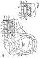
- FIG. 1 A torque wrench for tightening or loosening threaded connectors in accordance with the present invention is shown in FIG. 1.
- the torque wrench includes an engaging unit 1 which is turnable and is formed to engage a threaded connector 2 so that when the engaging unit 1 engages a threaded connector and is turned, it turns the threaded connector for tightening or loosening the same.
- the torque wrench includes further a fluid-operated power drive 2 which acts upon and turns the engaging unit 1 for tightening or loosening a threaded connector.
- the engaging unit 1 includes a ratchet wheel 3 which has a plurality of outer teeth and is provided with an engaging formation which is formed for example as a hexagonal projection 4 for attaching respective sockets to the projection.
- the sockets can be fitted on the threaded connectors, such as for example, nuts, bolt heads, etc.
- the engaging formation 4 can also be formed as a hexagonal opening which is directly fittable on the above mentioned threaded connectors.
- the engaging unit 1 further has a drive lever 5 which in its lower end is provided with a circular opening for rotatably receiving the ratchet wheel 3, and on its upper end is provided with a substantially circular head 6.
- a pawl 7 is displaceable in a recess of the lever 5 and provided with a plurality of teeth which engage with the teeth of the ratchet wheel 3.
- the pawl 7 is for example spring biased toward the ratchet 3.
- Two links or auxiliary elements 8 surround the lever 5 and are provided with a central opening 9 which also rotatably receives the ratchet 3.
- the links 8 have mounting openings 10 and 11 through which pins 12 and 13 extend for removably mounting the links 8 to a housing of the torque wrench.
- FIG. 2 shows one of the links 8 or auxiliary elements which is designed for the ratchet 3 suitable for a greater torque capacity, while one of the links or auxiliary elements 8' shown in FIG. 3 is designed for a ratchet having a lower torque capacity, as will be explained in detail hereinbelow.
- the difference between the links 8' of FIG. 3 and the links 8 of FIG. 2 is that the links 8' are provided with a projection 14.
- the fluid-operated power drive unit 2 includes a cylinder 15 which can be formed as a part of the housing of the torque wrench, and two pistons 16 and 17.
- the pistons 16 and 17 are cup-shaped, and the inner piston 17 is arranged in the interior of the outer piston 16.
- the inner piston 17 is connected with an intermediate piece 18 which in turn is pivotably connected with a bracket 19.
- the bracket 19 has a recess in which the head 6 of the lever 5 is received in a slidable and turnable manner.
- the bracket 19 can be spring biased toward the lever 5.
- a supply opening 20 is provided for supplying a working fluid into the cylinder 15 to the pistons 16 and 17 from a not shown source.
- the supply line 20 has an outlet 20' which opens behind the right end face of the piston 16 and an outlet 20'' which opens behind the right end of the piston 17.
- Additional piston means is further provided in an inner chamber 21 of the inner piston 17.
- the additional piston means is immovable relative to the cylinder 15 and includes an additional piston 22 provided with a piston rod 23.
- a throughgoing opening 24 extends through the piston rod 23 and has one end which opens through a passage 24' into the inner chamber 21 and the other end which is connected with a supply line 25 extending from a not shown source of a working fluid.
- the torque wrench in accordance with the present invention operates in the following manner.
- the links 8 are mounted in the torque wrench and a working fluid is supplied through the line 20 and outlet 20', 20'' into the cylinder 15, it applies pressure to both pistons 16 and 17 which have a relatively great combined piston area.
- Both pistons 16 and 17 are displaced to the left as shown in FIG. 1a, since the links 8 do not have a limiting projection, and in turn displace the intermediate piece 18 and the bracket 19 to the left so as to turn the lever 5 in a counterclockwise direction.
- the pawl 7 connected with the lever 5 turns the ratchet wheel 3 in the counterclockwise direction so as to tighten or loosen a threaded connector engaged by the engaging formation 4.
- FIG. 4 shows another embodiment of the torque wrench of the present invention.
- the return means for returning the pistons to their initial position does not have additional piston means 22, 23, 24 as in the embodiment of FIG. 1.
- the return means includes a spring drive 27 which cooperates with a projection 25 of a bracket 19'.
- the spring 27 is compressed.
- the spring 27 applies a return pressure against the projection 28 of the bracket 19', displaces the bracket 19' to the right, and turns the lever 5 in the clockwise direction.
Abstract
Description
- The present invention relates to a torque wrench. More particularly, it relates to such a torque wrench which has an engaging unit which engages a threaded connector and is turned so as to turn the threaded connector for tightening or loosening, and a fluid-operated drive unit including a cylinder and a piston movable in the cylinder and acting upon the engaging unit to turn the latter.
- Torque wrenches of the above-mentioned general type are widely known in the art.
The torque output of fluid-operated torque wrenches is based on the torque capacity of the engaging unit which can include for example a square drive, or in other words a square projection to which standard impact sockets can be attached. For example, a 2.5 cm (1 inch) square drive cannot take more than 4200 N m (3,100 ft./lbs.) since a torque higher than this would break off the square drive. A 3.8 cm (1.5 inch) square drive cannot take more than 16250 N m (12,000 ft./lbs.). Therefore the tools are designed so that the maximum torque output at maximum pressure does not exceed the maximum torque capacity of a square drive. It is therefore desirable to provide such a torque wrench in which the maximum torque output can be adjusted to the maximum torque capacity of a respective square drive, in a simple, convenient and fool-proof manner, since an error in selecting the maximum torque output can lead to destruction of the square drive. - A torque wrench for tightening or loosening a threaded connector is disclosed for example in my US-A 4 825 730. It has turnable engaging means arranged to be turned and to engage a threaded connector so as to tighten and loosen the latter in response to turning of the engaging means, power drive means for turning the engaging means to perform a stroke, means for connecting the power drive means with the engaging means, and exchangeable auxiliary elements connectable with said power drive means. The torque wrench of this reference does not allow application of a smaller pressure or a greater pressure correspondingly. Another device is disclosed in the German document DE-A-1964076 but this does not disclose specially designed means for simple and efficient variation of a pressure applied by the device.
- Accordingly, it is an object of the present invention to provide a torque wrench of the above-mentioned general type, which avoids the disadvantages of the prior art.
- More particularly it is an object of the present invention to provide a torque wrench in which the maximum torque output can be adjusted to the maximum torque capacity of a square drive, simply, reliably and in a fool-proof manner.
- In keeping with these objects and with others which will become apparent hereinafter, a torque wrench according to the present invention comprises turnable engaging means arranged to be turned and to engage a threaded connector so as to tighten or loosen the latter in response to turning of said engaging means; power drive means for turning said engaging means to perform a power stroke; means for connecting said power drive means with said engaging means; and comprising at least two exchangeable auxiliary elements which are releasably connectable with said power drive means whereby said power drive means includes fluid-operated cylinder-piston means provided with a cylinder and two pistons, said pistons being movable so that during said power stroke when one piston with a smaller piston area is moved it applies a smaller pressure to said engaging means to provide a smaller torque, while when both said pistons with a greater combined piston area are moved together they apply a greater pressure to said engaging means to provide a greater torque, and a first of said auxiliary elements is formed so that it blocks movement of the other of said pistons of said fluid-operated drive means, so as to allow the movement of only said one piston, whereas a second auxiliary element is formed so that it allows movement of said other of said pistons.
- The invention will now be further described, by way of example, with reference to the accompanying drawings, in which:-
- FIG. 1 is a side view of a torque wrench in accordance with the present invention;
- FIG 1a is a side view corresponding to the view of FIG. 1, but showing the torque wrench in a different position;
- FIGS. 2 and 3 are views showing two different modifications of a link of the torque wrench of FIG. 1, and
- FIG. 4 is a view showing a further embodiment of a torque wrench in accordance with the invention.
- A torque wrench for tightening or loosening threaded connectors in accordance with the present invention is shown in FIG. 1. The torque wrench includes an engaging unit 1 which is turnable and is formed to engage a threaded
connector 2 so that when the engaging unit 1 engages a threaded connector and is turned, it turns the threaded connector for tightening or loosening the same. The torque wrench includes further a fluid-operatedpower drive 2 which acts upon and turns the engaging unit 1 for tightening or loosening a threaded connector. - The engaging unit 1 includes a
ratchet wheel 3 which has a plurality of outer teeth and is provided with an engaging formation which is formed for example as ahexagonal projection 4 for attaching respective sockets to the projection. The sockets can be fitted on the threaded connectors, such as for example, nuts, bolt heads, etc. It is to be understood that theengaging formation 4 can also be formed as a hexagonal opening which is directly fittable on the above mentioned threaded connectors. The engaging unit 1 further has adrive lever 5 which in its lower end is provided with a circular opening for rotatably receiving theratchet wheel 3, and on its upper end is provided with a substantiallycircular head 6. Finally, a pawl 7 is displaceable in a recess of thelever 5 and provided with a plurality of teeth which engage with the teeth of theratchet wheel 3. The pawl 7 is for example spring biased toward theratchet 3. Two links orauxiliary elements 8 surround thelever 5 and are provided with acentral opening 9 which also rotatably receives theratchet 3. Thelinks 8 have mountingopenings pins 12 and 13 extend for removably mounting thelinks 8 to a housing of the torque wrench. FIG. 2 shows one of thelinks 8 or auxiliary elements which is designed for theratchet 3 suitable for a greater torque capacity, while one of the links or auxiliary elements 8' shown in FIG. 3 is designed for a ratchet having a lower torque capacity, as will be explained in detail hereinbelow. The difference between the links 8' of FIG. 3 and thelinks 8 of FIG. 2 is that the links 8' are provided with aprojection 14. - The fluid-operated
power drive unit 2 includes acylinder 15 which can be formed as a part of the housing of the torque wrench, and twopistons pistons inner piston 17 is arranged in the interior of theouter piston 16. Theinner piston 17 is connected with anintermediate piece 18 which in turn is pivotably connected with abracket 19. Thebracket 19 has a recess in which thehead 6 of thelever 5 is received in a slidable and turnable manner. Thebracket 19 can be spring biased toward thelever 5. Asupply opening 20 is provided for supplying a working fluid into thecylinder 15 to thepistons supply line 20 has an outlet 20' which opens behind the right end face of thepiston 16 and an outlet 20'' which opens behind the right end of thepiston 17. - Additional piston means is further provided in an
inner chamber 21 of theinner piston 17. The additional piston means is immovable relative to thecylinder 15 and includes anadditional piston 22 provided with apiston rod 23. Athroughgoing opening 24 extends through thepiston rod 23 and has one end which opens through a passage 24' into theinner chamber 21 and the other end which is connected with asupply line 25 extending from a not shown source of a working fluid. - The torque wrench in accordance with the present invention operates in the following manner. When the
links 8 are mounted in the torque wrench and a working fluid is supplied through theline 20 and outlet 20', 20'' into thecylinder 15, it applies pressure to bothpistons pistons links 8 do not have a limiting projection, and in turn displace theintermediate piece 18 and thebracket 19 to the left so as to turn thelever 5 in a counterclockwise direction. The pawl 7 connected with thelever 5 turns theratchet wheel 3 in the counterclockwise direction so as to tighten or loosen a threaded connector engaged by theengaging formation 4. The position of thelever 5 after turning is shown in a broken line in Figure 1. Then the supply of fluid through theline 20 is interrupted, and the working fluid is supplied through theline 25. The working fluid through thethroughgoing opening 24 and passage 24' enters theinner chamber 21 and displaces thepistons bracket 19 is also moved to the right and turns thelever 5 in a clockwise direction. During this turning of thelever 5 in the opposite direction, the teeth of the pawl 7 just slip over the teeth of theratchet wheel 3 without turning the latter. - When however it is necessary to use the engaging unit for tightening or loosening smaller threaded connectors which engaging unit therefore must have a lower maximum torque capacity, the
links 8 are removed and the links 8' are mounted in the torque wrench. Since the links 8' are provided with theprojections 14 which extend in the path of movement of theouter piston 16, theouter piston 16 cannot move to the left during the supply of the working fluid through thesupply line 20 into thecylinder 15. In this situation only theinner piston 17 which has a smaller piston area than the combined area of both pistons, is moved to the left under the action of the working fluid and therefore provides for a lower torque output of thelever 5 which corresponds to the lower maximum torque capacity of this engaging unit. - FIG. 4 shows another embodiment of the torque wrench of the present invention. Here, the return means for returning the pistons to their initial position does not have additional piston means 22, 23, 24 as in the embodiment of FIG. 1. Instead, the return means includes a
spring drive 27 which cooperates with aprojection 25 of a bracket 19'. During the displacement of the piston or pistons to the left for turning thelever 5 in the counterclockwise direction, thespring 27 is compressed. When afterwards the working fluid is discharged from thecylinder 15 back to its source, thespring 27 applies a return pressure against theprojection 28 of the bracket 19', displaces the bracket 19' to the right, and turns thelever 5 in the clockwise direction. - Various modifications of the illustrated embodiments are possible within the scope of the following claims.
Claims (10)
- A torque wrench for tightening or loosening of threaded connectors, comprising turnable engaging means (1) arranged to be turned and to engage a threaded connector so as to tighten or loosen the latter in response to turning of said engaging means; power drive means (2) for turning said engaging means (1) to perform a power stroke; means for connecting said power drive means with said engaging means; and comprising at least two exchangeable auxiliary elements (8, 8') which are releasably connectable with said power drive means (2), characterized in that,- said power drive means (2) includes fluid-operated cylinder-piston means (2, 16, 17) provided with a cylinder (15) and two pistons (16, 17), said pistons (16, 17) being moveable so that during said power stroke when one piston (17) with a smaller piston area is moved it applies a smaller pressure to said engaging means (1) to provide a smaller torque, while when both said pistons (16, 17) with a greater combined piston area are moved together they apply a greater pressure to said engaging means (1) to provide a greater torque, and- a first (8') of said auxiliary elements is formed so that it blocks movement of the other (16) of said pistons of said fluid-operated drive means (2), so as to allow the movement of only said one piston (17), whereas a second auxiliary element (8) is formed so that it allows movement of said other (16) of said pistons.
- A torque wrench as defined in claim 1, wherein at least one (16) of said pistons of said fluid-operated drive means (2) is hollow and has an inner space, the other (17) of said pistons of said fluid-operated drive means (2) being arranged in said inner space of said one piston (16).
- A torque wrench as defined in claim 1 or claim 2, wherein one (16) of said pistons is connected with said engaging means (1); and further comprising connecting means (18, 19) for connecting said one piston (16) with said engaging means (1).
- A torque wrench as defined in any one preceding claim, wherein said power drive means (2) is arranged to turn said engaging means (1) in a first direction; and further comprising return means (22, 23, 24; 27) arranged to turn said engaging means (1) in an opposite direction.
- A torque wrench as defined in claim 4, wherein said return means (27) for turning said engaging means in an opposite direction includes spring means (27) acting on said engaging means (1).
- A torque wrench as defined in claim 4, wherein one (17) of said pistons has an inner chamber (21), said return means (22, 23, 24) including a member having a throughoing opening (24) which opens into said inner chamber (21) so that when a working medium is supplied through said opening (24) into said inner chamber (21), said pistons (16, 17) are moved to move said engaging means (1) in an opposite direction.
- A torque wrench as defined in claim 6, wherein said return means (22, 23, 24) includes an additional piston (22) arranged to abut against said one piston (17), and a piston rod (23) connected with said additional piston (22), said throughgoing opening (24) being provided in said piston rod (23) of said piston means.
- A torque wrench as defined in any one preceding claim, wherein said first auxiliary element (8') is releasably connectable with said power drive means (2).
- A torque wrench as defined in any one preceding claim, wherein said first auxiliary element (8) has a projection (14) which extends toward said other piston (16) of said fluid-operated drive means (2) and prevents the movement of said other piston (16).
- A torque wrench as defined in claim 9, wherein said second auxiliary element (8) is releasably connectable with said power drive means (2) and formed so as to allow the movement of both said pistons (16, 17) of said fluid-operated drive means (2) together.
Applications Claiming Priority (3)
| Application Number | Priority Date | Filing Date | Title |
|---|---|---|---|
| US07/505,976 US5005447A (en) | 1989-10-05 | 1990-04-06 | Torque wrench |
| US505976 | 1990-04-06 | ||
| PCT/US1991/002469 WO1991015338A1 (en) | 1990-04-06 | 1991-04-08 | Torque wrench |
Publications (3)
| Publication Number | Publication Date |
|---|---|
| EP0478760A1 EP0478760A1 (en) | 1992-04-08 |
| EP0478760A4 EP0478760A4 (en) | 1992-10-14 |
| EP0478760B1 true EP0478760B1 (en) | 1994-12-07 |
Family
ID=24012659
Family Applications (1)
| Application Number | Title | Priority Date | Filing Date |
|---|---|---|---|
| EP91908708A Expired - Lifetime EP0478760B1 (en) | 1990-04-06 | 1991-04-08 | Torque wrench |
Country Status (7)
| Country | Link |
|---|---|
| US (1) | US5005447A (en) |
| EP (1) | EP0478760B1 (en) |
| JP (1) | JPH0714593B2 (en) |
| AT (1) | ATE115026T1 (en) |
| DE (1) | DE69105688T2 (en) |
| ES (1) | ES2067931T3 (en) |
| WO (1) | WO1991015338A1 (en) |
Families Citing this family (12)
| Publication number | Priority date | Publication date | Assignee | Title |
|---|---|---|---|---|
| DE4042070C2 (en) * | 1990-01-13 | 1995-06-08 | Wagner Paul Heinz | Hydraulic power wrench |
| FR2657039B1 (en) * | 1990-01-13 | 1996-01-05 | Wagner Paul Heinz | PRESSURE DRIVEN MOTORIZED SCREWDRIVER. |
| US5329833A (en) * | 1992-07-31 | 1994-07-19 | Sergan Anthony J | Bimodal hydraulic reciprocating torque actuator |
| US6112622A (en) * | 1999-05-03 | 2000-09-05 | Unex Corporation | Fluid-operated tool |
| US6260444B1 (en) * | 1999-06-23 | 2001-07-17 | John K. Junkers | Power tool |
| GB0014416D0 (en) * | 2000-06-13 | 2000-08-09 | More Nicholas | Hydraulic torque wrench |
| US6546839B1 (en) | 2000-08-22 | 2003-04-15 | Titantechnologies International, Inc. | Flow regulation device |
| US6802235B2 (en) | 2002-01-04 | 2004-10-12 | Unex Corporation | Fluid-operated torque wrench |
| MX2010002058A (en) * | 2010-02-22 | 2011-08-31 | Luis Gerardo Oyervides Ochoa | Hydraulic wrench with manual actuation for high-torque tightening and loosening. |
| US9550282B2 (en) * | 2014-04-22 | 2017-01-24 | John D. Davis | Compact hydraulic torque wrench cartridge |
| GB2558536A (en) * | 2016-11-14 | 2018-07-18 | Torque Tension Systems Ltd | A hydraulic torque wrench |
| US11135706B2 (en) | 2017-10-06 | 2021-10-05 | Enerpac Tool Group Corp. | Industrial tool and drive system for same |
Family Cites Families (7)
| Publication number | Priority date | Publication date | Assignee | Title |
|---|---|---|---|---|
| DE1964076C3 (en) * | 1969-12-22 | 1978-04-27 | G.L. Rexroth Gmbh, 8770 Lohr | Working cylinder with rapid traverse and power stroke |
| JPS5336800A (en) * | 1976-09-16 | 1978-04-05 | Sumitomo Metal Ind | Hydraulic wrench |
| JPS53117174A (en) * | 1977-03-22 | 1978-10-13 | Sakunao Tanaka | Double cylinder structure and operating device thereof |
| US4524651A (en) * | 1981-04-03 | 1985-06-25 | Paul-Heinz Wagner | Power wrench |
| DE8435272U1 (en) * | 1984-12-01 | 1985-02-28 | Wagner, Paul-Heinz, 5203 Much | HYDRAULIC SCREWDRIVER |
| US4825730A (en) * | 1987-09-29 | 1989-05-02 | Junkers John K | Fluid operated wrench |
| US9376225B2 (en) | 2009-07-02 | 2016-06-28 | Orihiro Engineering Co., Ltd. | Vertical filling and packaging machine and method of manufacturing packaging bag with content |
-
1990
- 1990-04-06 US US07/505,976 patent/US5005447A/en not_active Expired - Lifetime
-
1991
- 1991-04-08 EP EP91908708A patent/EP0478760B1/en not_active Expired - Lifetime
- 1991-04-08 WO PCT/US1991/002469 patent/WO1991015338A1/en active IP Right Grant
- 1991-04-08 DE DE69105688T patent/DE69105688T2/en not_active Expired - Fee Related
- 1991-04-08 ES ES91908708T patent/ES2067931T3/en not_active Expired - Lifetime
- 1991-04-08 AT AT91908708T patent/ATE115026T1/en not_active IP Right Cessation
- 1991-04-08 JP JP3508346A patent/JPH0714593B2/en not_active Expired - Lifetime
Also Published As
| Publication number | Publication date |
|---|---|
| JPH04503778A (en) | 1992-07-09 |
| JPH0714593B2 (en) | 1995-02-22 |
| DE69105688D1 (en) | 1995-01-19 |
| EP0478760A4 (en) | 1992-10-14 |
| ATE115026T1 (en) | 1994-12-15 |
| EP0478760A1 (en) | 1992-04-08 |
| DE69105688T2 (en) | 1995-04-20 |
| US5005447A (en) | 1991-04-09 |
| ES2067931T3 (en) | 1995-04-01 |
| WO1991015338A1 (en) | 1991-10-17 |
Similar Documents
| Publication | Publication Date | Title |
|---|---|---|
| EP0478760B1 (en) | Torque wrench | |
| US4825730A (en) | Fluid operated wrench | |
| EP1063060B1 (en) | Power tool | |
| USRE33951E (en) | Fluid operated wrench | |
| US6298752B1 (en) | Continuous fluid-operated wrench | |
| US5016502A (en) | Power wrench | |
| US4706526A (en) | Fluid operated wrench | |
| EP1052067B1 (en) | Fluid-operated tool | |
| US4663997A (en) | Fluid-operated wrench | |
| EP0386355A1 (en) | Power wrench | |
| US5029497A (en) | Continuous ratchet drive | |
| CA2412817C (en) | Torque wrench | |
| EP1086785B1 (en) | Fluid-operated tool | |
| EP0504331B1 (en) | Fluid-operated wrench | |
| AU2001266144A1 (en) | Torque wrench | |
| EP0324050A1 (en) | Torque Wrench | |
| US3466953A (en) | Ratchet wrench with hydraulically operated lock | |
| EP0230461B1 (en) | Power driven replaceable socket ratchet wrench | |
| JPS634619Y2 (en) | ||
| AU5660600A (en) | Power tool |
Legal Events
| Date | Code | Title | Description |
|---|---|---|---|
| PUAI | Public reference made under article 153(3) epc to a published international application that has entered the european phase |
Free format text: ORIGINAL CODE: 0009012 |
|
| AK | Designated contracting states |
Kind code of ref document: A1 Designated state(s): AT BE CH DE DK ES FR GB GR IT LI LU NL SE |
|
| 17P | Request for examination filed |
Effective date: 19920316 |
|
| A4 | Supplementary search report drawn up and despatched |
Effective date: 19920827 |
|
| AK | Designated contracting states |
Kind code of ref document: A4 Designated state(s): AT BE CH DE DK ES FR GB GR IT LI LU NL SE |
|
| 17Q | First examination report despatched |
Effective date: 19930826 |
|
| GRAA | (expected) grant |
Free format text: ORIGINAL CODE: 0009210 |
|
| ITF | It: translation for a ep patent filed |
Owner name: INTERPATENT ST.TECN. BREV. |
|
| AK | Designated contracting states |
Kind code of ref document: B1 Designated state(s): AT BE CH DE DK ES FR GB GR IT LI LU NL SE |
|
| PG25 | Lapsed in a contracting state [announced via postgrant information from national office to epo] |
Ref country code: GR Free format text: LAPSE BECAUSE OF FAILURE TO SUBMIT A TRANSLATION OF THE DESCRIPTION OR TO PAY THE FEE WITHIN THE PRESCRIBED TIME-LIMIT Effective date: 19941207 Ref country code: DK Effective date: 19941207 |
|
| REF | Corresponds to: |
Ref document number: 115026 Country of ref document: AT Date of ref document: 19941215 Kind code of ref document: T |
|
| REF | Corresponds to: |
Ref document number: 69105688 Country of ref document: DE Date of ref document: 19950119 |
|
| REG | Reference to a national code |
Ref country code: GR Ref legal event code: FG4A Free format text: 3014496 |
|
| ET | Fr: translation filed | ||
| PGFP | Annual fee paid to national office [announced via postgrant information from national office to epo] |
Ref country code: LU Payment date: 19950401 Year of fee payment: 5 |
|
| REG | Reference to a national code |
Ref country code: ES Ref legal event code: FG2A Ref document number: 2067931 Country of ref document: ES Kind code of ref document: T3 |
|
| PGFP | Annual fee paid to national office [announced via postgrant information from national office to epo] |
Ref country code: GB Payment date: 19950403 Year of fee payment: 5 |
|
| PGFP | Annual fee paid to national office [announced via postgrant information from national office to epo] |
Ref country code: ES Payment date: 19950410 Year of fee payment: 5 |
|
| PGFP | Annual fee paid to national office [announced via postgrant information from national office to epo] |
Ref country code: SE Payment date: 19950411 Year of fee payment: 5 |
|
| PGFP | Annual fee paid to national office [announced via postgrant information from national office to epo] |
Ref country code: FR Payment date: 19950424 Year of fee payment: 5 |
|
| PGFP | Annual fee paid to national office [announced via postgrant information from national office to epo] |
Ref country code: BE Payment date: 19950426 Year of fee payment: 5 |
|
| PGFP | Annual fee paid to national office [announced via postgrant information from national office to epo] |
Ref country code: AT Payment date: 19950428 Year of fee payment: 5 |
|
| PGFP | Annual fee paid to national office [announced via postgrant information from national office to epo] |
Ref country code: NL Payment date: 19950430 Year of fee payment: 5 |
|
| PGFP | Annual fee paid to national office [announced via postgrant information from national office to epo] |
Ref country code: CH Payment date: 19950524 Year of fee payment: 5 |
|
| PGFP | Annual fee paid to national office [announced via postgrant information from national office to epo] |
Ref country code: DE Payment date: 19950629 Year of fee payment: 5 |
|
| PLBE | No opposition filed within time limit |
Free format text: ORIGINAL CODE: 0009261 |
|
| STAA | Information on the status of an ep patent application or granted ep patent |
Free format text: STATUS: NO OPPOSITION FILED WITHIN TIME LIMIT |
|
| 26N | No opposition filed | ||
| REG | Reference to a national code |
Ref country code: GR Ref legal event code: MM2A Free format text: 3014496 |
|
| PG25 | Lapsed in a contracting state [announced via postgrant information from national office to epo] |
Ref country code: LU Free format text: LAPSE BECAUSE OF NON-PAYMENT OF DUE FEES Effective date: 19960408 Ref country code: GB Effective date: 19960408 Ref country code: AT Effective date: 19960408 |
|
| PG25 | Lapsed in a contracting state [announced via postgrant information from national office to epo] |
Ref country code: SE Effective date: 19960409 Ref country code: ES Free format text: LAPSE BECAUSE OF NON-PAYMENT OF DUE FEES Effective date: 19960409 |
|
| PG25 | Lapsed in a contracting state [announced via postgrant information from national office to epo] |
Ref country code: LI Effective date: 19960430 Ref country code: CH Effective date: 19960430 Ref country code: BE Effective date: 19960430 |
|
| BERE | Be: lapsed |
Owner name: JUNKERS JOHN K. Effective date: 19960430 |
|
| PG25 | Lapsed in a contracting state [announced via postgrant information from national office to epo] |
Ref country code: NL Effective date: 19961101 |
|
| GBPC | Gb: european patent ceased through non-payment of renewal fee |
Effective date: 19960408 |
|
| REG | Reference to a national code |
Ref country code: CH Ref legal event code: PL |
|
| PG25 | Lapsed in a contracting state [announced via postgrant information from national office to epo] |
Ref country code: FR Effective date: 19961227 |
|
| PG25 | Lapsed in a contracting state [announced via postgrant information from national office to epo] |
Ref country code: DE Effective date: 19970101 |
|
| NLV4 | Nl: lapsed or anulled due to non-payment of the annual fee |
Effective date: 19961101 |
|
| EUG | Se: european patent has lapsed |
Ref document number: 91908708.0 |
|
| REG | Reference to a national code |
Ref country code: FR Ref legal event code: ST |
|
| REG | Reference to a national code |
Ref country code: ES Ref legal event code: FD2A Effective date: 19990503 |
|
| PG25 | Lapsed in a contracting state [announced via postgrant information from national office to epo] |
Ref country code: IT Free format text: LAPSE BECAUSE OF NON-PAYMENT OF DUE FEES;WARNING: LAPSES OF ITALIAN PATENTS WITH EFFECTIVE DATE BEFORE 2007 MAY HAVE OCCURRED AT ANY TIME BEFORE 2007. THE CORRECT EFFECTIVE DATE MAY BE DIFFERENT FROM THE ONE RECORDED. Effective date: 20050408 |