EP0468107A1 - Transmission - Google Patents
Transmission Download PDFInfo
- Publication number
- EP0468107A1 EP0468107A1 EP90308034A EP90308034A EP0468107A1 EP 0468107 A1 EP0468107 A1 EP 0468107A1 EP 90308034 A EP90308034 A EP 90308034A EP 90308034 A EP90308034 A EP 90308034A EP 0468107 A1 EP0468107 A1 EP 0468107A1
- Authority
- EP
- European Patent Office
- Prior art keywords
- gear
- sleeve
- shift
- driven
- slide
- Prior art date
- Legal status (The legal status is an assumption and is not a legal conclusion. Google has not performed a legal analysis and makes no representation as to the accuracy of the status listed.)
- Granted
Links
Images


Classifications
-
- F—MECHANICAL ENGINEERING; LIGHTING; HEATING; WEAPONS; BLASTING
- F16—ENGINEERING ELEMENTS AND UNITS; GENERAL MEASURES FOR PRODUCING AND MAINTAINING EFFECTIVE FUNCTIONING OF MACHINES OR INSTALLATIONS; THERMAL INSULATION IN GENERAL
- F16H—GEARING
- F16H3/00—Toothed gearings for conveying rotary motion with variable gear ratio or for reversing rotary motion
- F16H3/02—Toothed gearings for conveying rotary motion with variable gear ratio or for reversing rotary motion without gears having orbital motion
- F16H3/08—Toothed gearings for conveying rotary motion with variable gear ratio or for reversing rotary motion without gears having orbital motion exclusively or essentially with continuously meshing gears, that can be disengaged from their shafts
- F16H3/087—Toothed gearings for conveying rotary motion with variable gear ratio or for reversing rotary motion without gears having orbital motion exclusively or essentially with continuously meshing gears, that can be disengaged from their shafts characterised by the disposition of the gears
- F16H3/089—Toothed gearings for conveying rotary motion with variable gear ratio or for reversing rotary motion without gears having orbital motion exclusively or essentially with continuously meshing gears, that can be disengaged from their shafts characterised by the disposition of the gears all of the meshing gears being supported by a pair of parallel shafts, one being the input shaft and the other the output shaft, there being no countershaft involved
-
- F—MECHANICAL ENGINEERING; LIGHTING; HEATING; WEAPONS; BLASTING
- F16—ENGINEERING ELEMENTS AND UNITS; GENERAL MEASURES FOR PRODUCING AND MAINTAINING EFFECTIVE FUNCTIONING OF MACHINES OR INSTALLATIONS; THERMAL INSULATION IN GENERAL
- F16H—GEARING
- F16H3/00—Toothed gearings for conveying rotary motion with variable gear ratio or for reversing rotary motion
- F16H3/02—Toothed gearings for conveying rotary motion with variable gear ratio or for reversing rotary motion without gears having orbital motion
- F16H3/08—Toothed gearings for conveying rotary motion with variable gear ratio or for reversing rotary motion without gears having orbital motion exclusively or essentially with continuously meshing gears, that can be disengaged from their shafts
- F16H3/10—Toothed gearings for conveying rotary motion with variable gear ratio or for reversing rotary motion without gears having orbital motion exclusively or essentially with continuously meshing gears, that can be disengaged from their shafts with one or more one-way clutches as an essential feature
-
- F—MECHANICAL ENGINEERING; LIGHTING; HEATING; WEAPONS; BLASTING
- F16—ENGINEERING ELEMENTS AND UNITS; GENERAL MEASURES FOR PRODUCING AND MAINTAINING EFFECTIVE FUNCTIONING OF MACHINES OR INSTALLATIONS; THERMAL INSULATION IN GENERAL
- F16H—GEARING
- F16H63/00—Control outputs from the control unit to change-speed- or reversing-gearings for conveying rotary motion or to other devices than the final output mechanism
- F16H63/02—Final output mechanisms therefor; Actuating means for the final output mechanisms
- F16H63/08—Multiple final output mechanisms being moved by a single common final actuating mechanism
- F16H63/16—Multiple final output mechanisms being moved by a single common final actuating mechanism the final output mechanisms being successively actuated by progressive movement of the final actuating mechanism
- F16H63/18—Multiple final output mechanisms being moved by a single common final actuating mechanism the final output mechanisms being successively actuated by progressive movement of the final actuating mechanism the final actuating mechanism comprising cams
Definitions
- the present invention relates to a transmission, and more particularly to a vehicle-used totally meshing automatic transmission.
- stageless transmission is developed to improve the above two transmissions.
- Two advantages of stageless transmission are first the structure is simple and it can be easily controlled, and second the engine can always operate at economic speed to output power with highest efficiency.
- the stageless transmission has two shortcomings one of which is the speed-changing control is slow and often it will change shift position by means of abruptly stepping down the accelerator, and the other of which is the driving chain is closely clamped the wheel disks and thus the frictional loss is very large. The stageless transmission is thus not widely used due to the above two drawbacks.
- the control thereof is sensive and the action is actual so that the engine can be kept in most economic operating state with highest efficiency.
- the present invention includes :
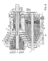
- the transmission of the present invention includes an input shaft 1, a driving gear assembly 2, an advancing shift controller assembly 3, a backing gear set 4, a driven shaft 5, a driven gear assembly 6, an advancing/backing/neutral shift controller assembly 7, an advancing/backing gear assembly 8, an output shaft 9 and a housing 10.
- the input shaft 1 extends into the housing 10 and serves as a driving shaft.
- the driving gear assembly 2 includes five driving gear sleeves 21,22,23,24,25 with increasing diameters. The number of the driving gear sleeves equals to that of the shifts.
- the five driving gear sleeves are telescoped on entering end portion of the input shaft 1 in such a manner that the input shaft 1 is loosely sleeved by a driving first shift spring 211 which is sleeved by the driving first shift gear sleeve 21 which is further sleeved by a driving second shift spring 221 which is sleeved by the driving second shift gear sleeve 22 which is sleeved by a driving third shift spring 231 which is further sleeved by the driving third shift gear sleeve 23 which is sleeved by a driving fourth shift spring 241 which is sleeved by the driving fourth shift gear sleeve 24 which is further sleeved by a driving fifth shift
- Each driving shift spring is not directly closely sleeved on its lower driving shift gear sleeve and a clearance exists therebetween.
- the driving shift gear sleeves are respectively associated with bearings 212,222,232,242,252 and a bearing 26 is disposed externally to connect the whole driving gear assembly 2 with the housing 10.
- the advancing shift controller assembly 3 is fitted on other end of the input shaft 1 by a controllably rotatable screw rod 31 meshing with a shift gear disk 32 which is fitted on other end of the input shaft. Inside the shift gear disk is disposed an advancing five shift engaging disk 33 and a driving first shift slide sleeve 34 is disposed on the input shaft which is sleeved by a driving first shift slide sleeve torque spring 341.
- the thickness of the driving first shift slide sleeve corresponds to that of the driving first shift spring and the thickness of the driving first shift slide sleeve torque spring 341 is fitted a driving second shift slide sleeve 35 which is sleeved by a driving second slide sleeve torque spring 351 which is sleeved by a driving third shift slide sleeve 36 which is sleeved by a driving third shift slide sleeve torque spring 361 which is further sleeved by a driving fourth slide sleeve 37 which is sleeved by a driving fourth slide sleeve torque spring 371 which is finally sleeved by a driving fifth shift slide sleeve 38 which is sleeved by a driving fifth slide sleeve torque spring 38.
- Each the driving shift slide sleeve torque spring is disposed between flange of each slide sleeve and each gear sleeve.
- the thickness of each driving shift slide sleeve corresponds to that of each driving shift spring and the thickness of each driving shift slide sleeve torque spring corresponds to that of each driving shift gear sleeve to form several layers.
- each driving shift slide sleeve is associated with a bearing 342, 352, 362, 372, 382. Therefore, the driving gear assembly 2 and advancing shift controller assembly 3 are formed by several layers and fitted on the left and right sides of the input shaft 1.
- a backing gear 40 which engages with an idle gear 41 which engages with a fixing shaft 43 through a bearing.
- the fixing shaft protrudes beyond the housing 10 to be fixed by a nut 44.
- bearings 11,12 At entering end and other end of the input shaft are disposed bearings 11,12 to associate with the housing 10 at an inner lower portion thereof.
- the driven gear assembly 6 includes five driven gear sleeves 65 ,64, 63, 62, 61 with increasing diameters. The number of the driven gear sleeves also equals to that of the shifts.
- the driven gear sleeves are telescoped on the driven shaft 5 corresponding to the driving gear assembly.
- the other end of the driven shaft 5 engages with an output shaft 9 and the driven shaft 5 is disposed at inner upper portion of the housing 10 in parallel to the input shaft 1.
- the driven shaft 5 is sleeved by a driven fifth shift gear sleeve 65 which is engaged with the driven shaft 5 by a key 651.
- the teeth of the driven fifth shift gear sleeve 65 mesh with the teeth of the driving fifth shift gear sleeve 25.
- the driven fifth shift gear sleeve is sleeved by a driven fourth shift spring 641 which is sleeved by a driven fourth gear sleeve 64 which is sleeved by a driven third shift spring 631 which is sleeved by a driven third shift gear sleeve 63 which is sleeved by a driven second shift spring 621 which is sleeved by a driven second shift gear sleeve which is sleeved by a driven first shift spring 611 which is finally sleeved by a driven first shift gear sleeve 61.
- Each driven shift spring is not directly closely fitted on each driven shift gear sleeve.
- Each driven shift gear sleeve engages with a bearing 612,622,632, 642,652 at one end and engages with a bearing 613, 623, 633, 643, 653 at the other end.
- the teeth of each driven shift gear sleeve mesh with the teeth of each driving shift gear sleeve.
- the driven gear assembly 6 is fixed to the housing 10 by a bearing 51.
- the advancing/backing/neutral shift controller assembly 7 is connected to a shifting disk 72 by a manual control lever 71 extending into the housing 10 and is fitted to one end of the driven shaft 5 near the driven gear assembly 6.
- the controller assembly 7 is further connected with an advancing/backing shift engaging disk 73 at other end of the shifting disk and is fitted to the driven shaft 5 by two layers of slide sleeves.
- the inner layer is advancing shift slide sleeve 75 which is sleeved by an advancing shift slide sleeve torque spring 751 located between a flange of the advancing shift slide sleeve and an advancing shift gear sleeve 81.
- One end of the advancing shift slide sleeve 75 is connected to a backing shift slide sleeve 76 of outer layer by a bearing 752.
- the backing shift slide sleeve 76 is sleeved by a backing shift slide sleeve torque spring 761 located between a flange of the backing shift slide sleeve and a backing shift gear sleeve 82.
- One end of the backing shift slide sleeve is connected with the housing 10 by a bearing 762.
- the advancing/backing gear assembly 8 is connected with the advancing/backing/neutral shift controller assembly 7.
- the advancing/backing gear assembly 8 is formed by two layers of gear sleeves.
- the inner layer is an advancing shift gear sleeve 81 and an advancing shift spring 811 is fitted therein.
- the advancing shift spring 811 is not directly closely fitted on the driven shaft.
- the advancing shift gear sleeve is connected with the housing 10 by a bearing 812 near the output shaft 9 and is connected with driven shaft by a bearing 813.
- the thickness of the advancing shift spring corresponds to that of the advancing shift slide sleeve
- the thickness of the advancing shift gear sleeve corresponds to that of the advancing shift slide sleeve torque spring.
- the advancing shift gear sleeve is sleeved by a backing shift gear sleeve 82 and a backing shift spring 821 is fitted therein and is not directly closely fitted on the advancing shift gear sleeve.
- the backing shift gear sleeve is connected with the housing 10 by a bearing 822 near the output shaft.
- the thickness of the backing shift spring corresponds to that of the backing shift slide sleeve and the thickness of the backing shift gear sleeve corresponds to that of the backing shift slide sleeve torque spring.
- the teeth of the backing shift gear sleeve mesh with the teeth of the idle gear and the driven shaft 5 is screwed to the output shaft 9 at one end of the advancing shift gear sleeve.
- the output shaft is fixed to the housing 10 by a bearing 9 and is extended outside the housing 10 for driving.
- the input shaft 1 is loosely sleeved by the driving first shift spring 211 which is sleeved by the driving first shift gear sleeve 21.
- a clearance therefore exists between the driving first shift spring and input shaft.
- the driving first shift spring is kept in a loose state and one end thereof is fixed on tooth end of inner surface of the driving first shift gear sleeve at position 213.
- Each shift gear sleeve is generally formed with an extending gear tooth portion inner side of which is associated with a ball bearing. Therefore, the gear tooth end is pivoted to the input shaft by a bearing 212 and other end thereof is fitted to a driving first shift slide sleeve 34 located on the input shaft.
- One end of the slide sleeve 34 has a flange 343 the thickness of which equals to that of the driving first shift gear sleeve.
- a driving first shift slide sleeve torque spring 3421 is disposed between the outer end of the driving first shift gear sleeve and the flange of the driving first shift slide sleeve.
- a slot 334 is formed on proper portion of the driving first shift slide sleeve.
- the slot 334 corresponds to a projection 10 of the input shaft, permitting the slide sleeve to slide within a certain distance.
- the lower end edge of the slide sleeve has a recess 345 which can receive other end 215 of the driving first shift spring.
- Fig.2 shows that the slide sleeve is not engaged with the spring and the projection of input shaft is located in the slot of slide sleeve near the spring to only drive the slide sleeve, making the same rotate together with the input shaft.
- Fig.3 shows that the driving first shift slide sleeve is forced to move toward the driving first shift spring end 215, making the spring end 215 go into the recess 345 of the slide sleeve and press the driving first shift spring. Because the input shaft is rotated, making the driving first shift slide sleeve rotate in same direction and the driving first shift spring is pressed to closely engage with the output shaft, the driving first shift spring will rotate in same direction, and because the other end of the driving first shift spring is engaged with the driving first shift gear sleeve, the driving first shift gear sleeve will also rotate in same direction.
- the projection 101 of the input shaft engages with the slot of the slide sleeve away from the spring.
- the restoring force of the driving first shift slide sleeve torque spring 343 will restore the sleeve.
- only the projection drives the slide sleeve to rotate in same direction.
- the driving first shift spring is not forced to engage with the input shaft, therefore the driving first shift spring and driving first shift gear sleeve both will not rotate following the input shaft.
- the driving gear assembly and advancing/backing shift gear assembly are disposed according to the same principle.
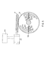
- Fig.4 the advancing shift controller assembly 3 is partially shown.
- An advancing five shift engaging disk 33 is connected with a shifting gear disk 32.
- the teeth of the shifting gear disk mesh with the thread of a thread rod 31.
- the thread rod is controllably rotated by a stepped motor 311 which is controlled by a microprocessor 312 which controls the torque output to guide the thread rod to rotate and make the shifting gear disk rotate.
- the microprocessor has many detecting measuring devices respectively connected with the input shaft, output shaft, accelerator, carburetor, brake disk and clutch to feedback various state data to the microprocessor for calculating the best present rotating speed data and determining the shift number and sending to the stepped motor for execution.
- Fig.4 shows a neutral shift state wherein the shifting gear disk is fitted to the input shaft 1.
- Two sides of the shifting gear disk are formed with five different shifting slots 321,322,323,324,325.
- the five pairs of shifting slots respectively receive engaging keys 331, 332,333,334,335 of the advancing five shift engaging disk.
- the five pairs of shifting slots are formed in the rotating direction of the gear and the interval therebetween is about 20 degrees.
- the first shift slot 321 is located at zero degree, engaging with a first shift engaging key 331, and the second shift slot 322 is located within zero degree to 20 degree, engaging with a second shift engaging key 332, and the third shift slot 323 is located within zero degree to 40 degree, engaging with a third shift engaging key 333, and the fourth shift slot 324 is located within zero degree to 60 degree, engaging with a fourth shift engaging key 334, and the fifth shift slot 325 is located within zero degree to 80 degree, engaging with a fifth shift engaging key 335.
- the left keys will go upward and the right keys will go downward.
- two corresponding keys are located respectively at zero degree and 180 degree positions.
- a state of Fig.5 will be formed wherein the first shift engaging key 311 slides away from the first shift slot 321 and the other second, third, fourth and fifth shift engaging keys are located in the second, third, fourth and fifth shift slots. But the engaging disk will not rotate and only the shifting gear disk will rotate about 20 degrees. When changing from original neutral shift to first shift, the first shift engaging key will make the first shift slide sleeve move. This is the working state of auto-shifting. Therefore, the microprocessor can be used to choose optimum shift to maximize the engine effect.
- Fig.6 shows the transmission operation under first shift.
- the stepped motor 311 in Fig.5 will drive thread rod 31, making the shifting gear disk 32 rotate for a certain angle to therefore make one end of the first shift engaging key 331 slide out of the first shift slot 321 of shifting gear disk 32 and make the other end thereof pressed toward the flange of driving first shift slide sleeve 34 and make the flange of driving first shift slide sleeve further pressed toward driving first shift slide sleeve torque spring 341.
- the recess of driving first shift slide sleeve at this time engages with projecting end of the driving first shift spring 211, making the same closely fitted on the input shaft 1 and carried by input shaft to rotate in same direction at same speed.
- the driving first shift gear sleeve 21 engaging with driving first shift spring 341 will rotate together therewith in same direction . Since the driving first shift slide sleeve 34 is engaged with projection and rotates in same direction, therefore it will rotate at a speed identical to that of input shaft 1, making the driving first shift gear sleeve 21 rotate at same speed.
- the driven first shift spring will be closely fitted on driven second shift gear sleeve 64, making driven first shift spring drive the driven second shift gear sleeve to rotate in reverse direction and make the driven second shift spring 641 rotate in reverse direction to be closely fitted on the driven third shift gear sleeve 63, making the driven third shift gear sleeve rotate in reverse direction to drive the driven third shift spring 631 to reversely rotate to be closely twisted on the driven fourth shift gear sleeve 62, making the driven fourth shift gear sleeve rotate reversely to drive the driven fourth shift spring 641 to be twisted on the driven fifth shift gear sleeve 65, making the driven fifth shift gear sleeve rotate reversely.
- an engaging key of driven fifth shift gear sleeve engages with the driven shaft to drive the driven shaft to rotate in reverse direction.
- a tooth number ratio exists between the driving gear set and driven gear set. Therefore, the speeds of input shaft and driven shaft can be identical or different.
- the driving and driven second, third, fourth and fifth shift gear sleeves mesh with each other, therefore the driven shift gear sleeve can make the driving shift gear sleeve rotate.
- the driving shift springs engaging with driving shift gear sleeves are not twisted on the higher shift gear sleeve. Therefore, the driving shift gear sleeves rotate in same direction as the input shaft.
- driving shift gear sleeves will rotate individually as an idling state which will not affect the rotation of driving first shift gear sleeve and driven gear set. The power will be sent from driving first shift to driven first shift and to output shaft.
- Fig.7 shows the transmission operation under third shift.
- the stepped motor 311 drives thread rod 31, making the shifting gear disk 32 rotate for another angle.
- the second engaging key 332 will slide out of the second shift slot 322 to form second shift state.
- the thread rod can further rotate for another angle from second zone angle to third zone angle.
- the third shift engaging key 333 will slide out of the third shift slot 323 to form third shift state.
- the first, second and third shift engaging key 331,332,333 all slide out of the first, second and third slots 321,322,323 as shown in Fig. 8.
- the three engaging keys engage with flanges of driving first, second, third shift slide sleeves 38,37,36 to make the driving first, second, third shift slide sleeve torque springs 381,371,361 forced and pressed and make the driving first, second ,third shift slide sleeves pressed toward driving first, second, third shift springs 211,221,231 and make the same respectively twisted on the surfaces of input shaft 1, driving first shift gear sleeve 21 and driving second shift gear sleeve 22 so that the input shaft will drive all first, second, third shift gear sleeves 21,22,23 to rotate in same direction at same speed.
- the driving second shift spring engages with driving first shift gear sleeve and is also suffered from rotating force of driving first shift, therefore the driving second shift gear sleeve will have rotating speed of driving first shift gear sleeve in addition to original input shaft speed.
- the driving third shift will have driving first shift gear sleeve rotating speed and driving second shift gear sleeve rotating speed in addition to input shaft rotating speed.
- driven shift gear sleeves 61, 62,63, 64, 65 rotate reversely and the driven first, second, third, fourth shift springs 611,612,613,614 also respectively are twisted on driven second, third, fourth and fifth shift gear sleeves, and driven fifth shift is engaged with the driving shaft to make the rotating speed of driven first, second shift gear sleeves sent from driving first, second shift gear sleeves smaller than the rotating speed sent from driving third shift gear sleeve toward driven third shift gear sleeve.
- the driving fourth and fifth shift springs are not closely twisted on the driving fourth and fifth shift gear sleeves and because the fourth and fifth shift engaging keys do not press down driving fourth and fifth shift slide sleeve to engage with the driving fourth and fifth shift spring, therefore the driving fourth and fifth shift gear sleeve will only drive the driving fourth and fifth shift springs to rotate following the driven fourth and fifth shifts at a speed sent therefrom but will not actually drive to form an idling state.
- the second and fourth shift transmission states are like the third shift and will not be described in detail hereinafter. Of course a tooth number ratio exists between driving third shift and driven third shift and thus the speed of driven third shift is different from that of driving third shift.
- Fig.9 shows the transmission operation under fifth shift state, wherein the stepped motor 311 drives the thread rod 31, making the shifting gear disk 32 further rotate for another angle to make five shift engaging keys 331, 332, 333,334,335 all slide out of the slots 321,322,323,324,325 of the shifting gear disk 32.
- the five keys respectively move the driving first, second, third, fourth and fifth shift slide sleeves 38,37,36,35,34 making the driving first, second, third, fourth, fifth shift slide sleeve torque springs 381, 371, 361, 351, 341 pressed.
- the driving first, second, third, fourth, fifth shift slide sleeves 38,37,36,35, 34 are respectively fitted to the driving first, second, third, fourth, fifth shift springs 211,212,213,214,215, making the driving first, second, third, fourth, fifth shift gear sleeves 21,22,23,24,25 rotate following the input shaft 1 in same direction.
- the driving fifth shift spring is twisted on the driving fourth shift gear sleeve and the driving fourth shift spring is twisted on the driving third shift gear sleeve and at the same time, the driving third shift spring is also twisted on the driving second shift gear sleeve and the driving second shift spring is twisted on driving first shift gear sleeve and the driving first shift gear sleeve is twisted on the input shaft, therefore in whole driving shift gear sleeves, the fifth shift gear sleeve has a fastest speed and the fourth one has a second fastest speed, and the third one has a third fastest speed, and the second one has a fourth fastest speed and the first one has a slowest speed.
- the speeds of input shaft and driving first through fifth shift gear sleeves all are sent to the driven first through fifth shift gear sleeves according to the tooth number ratio between driving and driven shift gear sleeves. Therefore, the driven fifth shift gear sleeve has a fastest speed and since the driven fifth shift gear sleeve is directly engaged with the driven shaft, thus it will transmit directly the sent speed to the driven shaft, and the speeds of driven fourth, third, second and first shift are gradually reduced.
- the driven fourth, third, second, first shift springs can not be closely twisted on driven fifth, fourth, third, second shift gear sleeves to form an idling-like state without actual driving. This is fifth shift transmission.
- the shift number can be increased or reduced according to the same principle.
- the thread rod will make the shifting gear disk rotate for an angle and another angle, making the engaging keys one by one slide out of the slots to press driving shift slide sleeves to engage with driving shift springs, making the driving shift gear sleeve driven by input shaft and rotate at different speeds which increase from first shift to fifth shift. Therefore, the rotating speed transmitted to the driven shaft also increases gradually and the rotating speed of the output shaft will thus increase gradually.
- the engaging keys will rebound into the slots of the shifting gear disk,and the driving shift slide sleeve will no more engage with the driving shift springs and rebound to original position, and the driving shift springs also no more be twisted on the driving shift gear sleeve or input shaft and will restore one shift by one shift to also make the driven shift gear sleeves rotate at gradually reduced speed shift by shift.
- the neutral state can be achieved.
- the shift position can be changed to the lower shift and then raised to the higher shift according to external conditions.
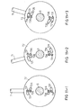
- Fig.11-1 shows the sectional view of the advancing/backing/neutral shift controller assembly 7, wherein the neutral shift condition is illustrated.
- the transmission is connected with an external manual control lever 71 which is connected with a shifting disk 72 and fitted on the driven shaft 5.
- the shifting disk 72 is fitted on the driven shaft 5.
- Two paris of slots are respectively formed on upper and lower sides of the shifting disk 72.
- the outer one is a backing shift slot 721.
- the upper backing shift slot faces right and the lower one faces left.
- In the backing shift slot is disposed a backing shift engaging key 731.
- the size of backing shift slot is about two to three times that of the engaging key.
- the inner slot is an advancing shift slot 726 which is under the backing shift slot 721.
- the advancing shift slot 726 faces right. Moreover, the slot 726 located under advancing shift is formed above the backing shift slot 721. If the lower backing shift slot 721 faces right, then the advancing shift slot 726 faces left.
- the size of advancing shift slot is also about two to three times that of engaging key.
- FIG. 11-2 shows the advancing/backing/neutral shift controller assembly 7 under backing shift state wherein the manual control lever 71 is turned left for a certain angle, making the backing shift engaging key 731 separate from backing shift slot 721 and the advancing shift engaging key 736 remain in the advancing shift slot 726 and only move from one end to the other end.
- Fig. 11-3 shows the controller assembly 7 under advancing shift state. At this time, the manual control lever 71 is turned right for a certain angle, making the advancing shift engaging key 736 separate from the advancing shift slot 726 and the backing shift engaging key 731 remain in the backing shift slot 721 and only move from one end to the other end.
- a control button can be used to control the stepped motor and thread rod to drive the advancing/backing shift gear disk to move without using a manual shifting lever.
- the output shaft Since the advancing shift gear sleeve is screwed on the output shaft, therefore the output shaft will output corresponding to the speed and direction of the driven shaft under each shift position. But the output shaft will rotate in a reverse direction of the rotating direction of the input shaft. Through the output shaft, engine transmits power outwardly to advance. At this time, the backing shift is located in outer layer and not twisted tightly and will not produce any effect.
- Fig. 12 shows the transmission under backing shift state, wherein the manual control lever is shifted to the backing position as shown in Fig. 11-2 and the backing shift engaging key 736 slides out of the backing shift slot to press the backing shift slide sleeve 74 of assembly 7, making the backing shift slide sleeve axially slide to press the backing shift slide sleeve torque spring 741, making the recess of backing shift slide sleeve engage with the projecting portion of the backing shift spring 821, making the backing shift spring twisted closely on the advancing shift gear sleeve 75 to drive the advancing shift gear sleeve to rotate, and since the advancing shift gear sleeve is screwed on the output shaft, the output shaft is also driven to rotate.
- the power is obtained in such a manner that the teeth of the backing shift gear sleeve mesh with the teeth of the idle gear 41 and the teeth of idle gear further mesh with the teeth of the backing gear 40 fitted to the input shaft 1 so that the backing gear sleeve rotates in same direction as the input shaft and the idle gear rotates in different direction from the input shaft. Therefore, the backing gear sleeve rotates in same direction as the input shaft while the advancing gear sleeve rotates in same direction as the input shaft and the power is transmitted from input shaft toward output shaft to produce a backing effect.
- the differences between the aforesaid advancing effect and this effect are the power transmitting path and direction and value. Therefore, the advancing and backing shifts are both controlled by manual control lever. When advancing, it will never back up and when backing up, it will never advance to keep the driving smooth and safe.
- the housing of this transmission is disposed according to each element. Because it pertains to totally meshing system and is supported by bearings to rotate, the elements all rotate at high speed during a long period, and heat is produced by frictional motion and a lubricating and cooling device is required.
- an oil pool is disposed under the housing and partial gears are immersed therein so that when rotating, a lubricating and cooling effect is obtained.
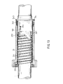
- Fig. 13 shows another embodiment of input shaft portion of this invention.
- a gear sleeve 21 is fitted on the input shaft 1.
- Upper end of the gear sleeve 21 has a gear portion.
- the whole sleeve 21 is integrally made.
- the gear portion extends beyond the outer surface of the sleeve 21.
- On inner surface of the gear sleeve 21 is disposed a bearing 212.
- Other end of the sleeve 21 engages with one end of a spring 211.
- the other end of the spring has a tapered portion 2111 with reduced inner diameter.
- a projection 101 is formed on the input shaft and a slide sleeve 34 is fitted to other end of the input shaft.
- the slide sleeve has a flange 343.
- a torque spring 341 is disposed between the flange and gear sleeve end.
- a slot is formed on the slide sleeve.
- the projection 10 is located at one end of the slot.
- the slide sleeve is not forced to slide toward gear sleeve.
- the slide sleeve 34 is forced to slide toward gear sleeve 21 and the torque spring 341 retracts and the projection 101 slides in the slot 344 from one end to the other end.
- the projection 101 engages with the slide sleeve and the input shaft rotates to drive the slide sleeve to rotate, when slide sleeve slides toward the spring, it will engages with the spring 211.
- the inner rear end of the slide sleeve has a tapered inner surface portion 347 which can more closely engage with the tapered portion 2111 of the spring, making the spring closely twisted on the input shaft to be driven to further retrially drive the gear sleeve.
- the slide sleeve When not forced, the slide sleeve will be rebounded to original position by torque spring. The spring will become loose and no more drive.
- the outer several gear sleeves are all provided with the projections and same elements.
- Fig. 15 shows a further embodiment of the input shaft portion, wherein a gear sleeve 21 is fitted on the input shaft 1.
- the gear sleeve has a gear portion at its one end and is formed integrally. The gear portion extends beyond the outer surface of the gear sleeve.
- the gear sleeve is provided with a bearing 21 near its gear portion end and a recess 215 at its rear end.
- a slide sleeve 34 is fitted on the other end of the input shaft 1.
- the slide sleeve has projecting portion 345 at its rear end and the input shaft has a projection 101.
- a slot 344 is formed on the slide sleeve to receive the projection 101 at its one end.
- Fig. 15 shows that the slide sleeve is not engaged with the gear sleeve.
- the projecting end 331 of the engaging key drives the slide sleeve to slide toward gear sleeve, making the recess 215 of the gear sleeve engage with projecting portion 345 and the projection of input shaft slide toward the other end.
- the input shaft rotates to drive the slide sleeve 34 to rotate and further drive the gear sleeve 21 to rotate.
- the slide sleeve slides back too, At this time,only the slide sleeve rotates and no driving effect is produced.
- the outer several layers are also provided with same elements.
- Fig. 17 shows another embodiment of input shaft portion of this invention, wherein a gear sleeve 21 is fitted on the input shaft 1 and a spring 211 is disposed whereby when the spring 211 is twisted, the inner diameter thereof is smaller than the outer diameter of the input shaft so that it can be fitted on the input shaft. When the external torque disappears, the resistant restoring torque of the spring will reduce the inner diameter to closely engage with the input shaft.
- One end of the spring is formed with a triangular projection and one end of the gear sleeve 21 is integrally formed with a gear 216.
- the inner diameter of the gear sleeve is slightly larger than the outer diameters of the spring 211 and slide sleeve 34.
- a recess 217 is formed on inner surface near the gear end for a projecting end 212 of the spring to engage with to restrict the spring so that the spring can only perform screwing movement.
- the slide sleeve 34 has a substantially triangular projecting end 348 at its one end and has a annular groove 347 receiving a ring member 343 which includes two semicircular members each having a projection 3431 formed with a hole 3432.
- a screw 3434 goes through the holes 3432 to rotatably fix the ring member 343 on the annular groove 347 of the slide sleeve 34.
- a projection 349 is suitable to be placed into a slot 218 of the gear sleeve 21.
- Each semicircular member has a projecting rod 3433 which is moved by the engaging key.
- a bearing 212 is further disposed at gear end of the gear sleeve.
- Fig. 18 shows that the ring member 343 is not moved by the engaging key and the triangular projecting end of the slide sleeve 34 engages with the triangular projecting end of the spring to abut against the spring, preventing the same from being twisted closely on the input shaft 1.
- the spring will not drive the gear sleeve 21 to rotate, and the projection of the slide sleeve 34 also engages with the slot 218 to prevent the slide sleeve from rotating.
- Fig. 19 shows that the ring member 343 is outward moved by the engaging key to drive the slide sleeve to outward move, and the projecting end of the slide sleeve no more engages with the projecting end of the spring.
- the projection of slide sleeve slides along the slot 218 of gear sleeve from one end toward the other end.
- the spring is free from torque and automatically screws tightly on the input shaft to be driven thereby, and since one end of the spring engages with the gear sleeve, the gear sleeve is also driven to rotate and since the slot of the gear sleeve engages with the projection of the slide sleeve, the slide sleeve is also driven to rotate.
- the gear sleeve outputs power outwardly.
- the aforesaid shifting gear disk of the advancing shift controller operates in reverse directions.
- the stepped motor outputs power in reverse direction, making the engaging key slide out of the shifting gear disk.
- the engaging key engages with the shifting disk, it is advancing shift, i.e. the original fifth shift effect is now neutral shift and original fourth shift is now first shift and accordingly, the original neutral shift is now fifth shift.
- the original advancing and backing shifts are now backing and advancing shift.
- the driving gear set can accordingly form the assembly with several layers.
Landscapes
- Engineering & Computer Science (AREA)
- General Engineering & Computer Science (AREA)
- Mechanical Engineering (AREA)
- Structure Of Transmissions (AREA)
- Control Of Transmission Device (AREA)
Abstract
Description
- The present invention relates to a transmission, and more particularly to a vehicle-used totally meshing automatic transmission.
- The experienced vehicle drivers all know that to drive an auto-shifting car is much easier than to drive a manually shifting car. Because when driving a manually shifting car, each shifting procedure requires six steps, i.e. setting free the accelerator, stepping down the clutch pedal, shifting the shift lever from original position into new position, setting free the clutch pedal, and then stepping down the accelerator. On a road with complicated traffic, doing such steps repeatedly will naturally make the driver bothered and impatient, and danger is apt to be caused. Moreover, when shifting, the accelerator is set free to thus cause power loss, and when shifting during going up an inclined plane, if the shifting lever is not properly moved to new position, the engine might be extinguished. Furthermore, because the shifting procedure is too complicated, the driver often is not willing to shift when the shifting is required. Therefore, the engine often operates at improper rotating speed to waste energy and cause engine damage. On the other hand, conventional auto-transmission has quite complex structure including planet gear sets, clutch, brake, controller, etc. and the manufacturing cost is relatively high, and all the elements require regular adjustment to increase service cost. Moreover, the transmission efficiency of auto-transmission is low and the power loss thereof is 18% greater than manual transmission. Thus, the auto-transmission can not be popularly applied.
- Therefore, stageless transmission is developed to improve the above two transmissions. Two advantages of stageless transmission are first the structure is simple and it can be easily controlled, and second the engine can always operate at economic speed to output power with highest efficiency. However, the stageless transmission has two shortcomings one of which is the speed-changing control is slow and often it will change shift position by means of abruptly stepping down the accelerator, and the other of which is the driving chain is closely clamped the wheel disks and thus the frictional loss is very large. The stageless transmission is thus not widely used due to the above two drawbacks.
- Therefore, a new transmission with high transmission efficiency is required to eliminate the aforesaid problems.
- It is a primary object of this invention to provide a transmission applying microprocessor which can according to engine rotating speed command a stepped motor to drive shifting disk to automatically shift into proper position. The control thereof is sensive and the action is actual so that the engine can be kept in most economic operating state with highest efficiency.
- It is a further object of this invention to provide a totally meshing auto-transmission having advantages of simplicity and high driving efficiency of manual transmission without disadvantages of complex operating procedure thereof and having better control effect than auto-transmission.
- It is still a further object of this invention to provide a transmission wherein when shifting, the vehicle can be continuously accelerated without interrupting the power transmission and more shifts can be added without increasing the complexity of structure and operation and by means of the microprocessor, the vehicle can be actually accelerated with strong and steady effect.
- Accordingly, the present invention includes :
- a housing which receives all element of this invention;
- an input shaft having a front half and a rear half portion;
- a driving gear assembly having several driving gear sleeves the number of which equals to that of the shifts, the driving gear sleeves having different diameters and being fitted on the front half portion of the input shaft in sequence from the small diameter one to large diameter one, each the driving gear sleeve being not rotarily driven by the input shaft;
- an advancing shift controller assembly having several slide sleeves with different diameters, the number of which equals to that of the shifts, the slide sleeves being fitted on the rear half portion of said input shaft in sequence from the small diameter one to large diameter one, a first controlling means being used to control the engagement and separation of the slide sleeves and corresponding driving gear sleeves to select the shift driven by the input shaft, each slide sleeve being rotated by said input shaft, the slide sleeve being capable of engaging with corresponding driving gear sleeve to rotate the same;
- a backing gear assembly having a backing gear fitted on rear end of the input shaft, the backing gear engaging with an idle gear;
- a driven shaft having a front portion, a middle portion and a rear portion;
- a driven gear assembly having several driven gear sleeves the number of which equals to that of the driving gear sleeves, the driven gear sleeves having different diameters and being fitted on the front portion of the driven shaft in sequence from small diameter one to large diameter one and meshing with the driving gear sleeves, each driven gear sleeve having a third coupling means which connects the driven gear sleeves with each other and connects the driven gear sleeves with the driven shaft whereby when each driving gear sleeve rotates, the driven gear sleeve meshing therewith is driven to rotate and rotarily drive in outward sequence each the driven gear sleeve and driven shaft;
- an advancing/backing shift gear assembly having two sets of gear sleeves with different diameters, the gear sleeves being fitted on the middle portion of the driven shaft in sequence from small diameter one to large diameter one, one of the gear sleeves being advancing gear sleeve, the other of the gear sleeves being a backing gear sleeve, the backing gear sleeve meshing with the idle gear, each gear sleeve having a fourth coupling means which connects the driven shaft with each gear sleeve whereby the driven shaft or idle gear can drive each gear sleeve to rotate;
- an advancing/backing/neutral controller assembly having two sets of slide sleeves with different diameters, the slide sleeves being fitted on the rear portion of the driven shaft from small diameter one to large diameter one, a second controlling means being used to control the separation and engagement of the slide sleeves and advancing/backing gear sleeves to select the advancing or backing or neutral shift, each slide sleeve driving corresponding gear sleeve to rotate; and
- an output shaft connected with the advancing/backing shift gear assembly to output outwardly.
- The invention as well as its many advantages may be further understood by reference to the following detailed description and drawings in which:
- Fig.1 is a sectional view of this invention in a neutral shift state;
- Fig.2 is a sectional view of first embodiment of input shaft in not fitted state;
- Fig.3 is a view according to Fig. 2, in which the input shaft is in a fitted state;
- Fig.4 is a sectional view of shifting gear disk in neutral state;
- Fig.5 is a sectional view according to Fig.4, in which the shifting gear disk is in first shift state;
- Fig.6 is a sectional view of this transmission in first shift state;
- Fig.7 is a sectional view of shifting gear disk in third shift state;
- Fig.8 is a sectional view of this transmission in third shift state;
- Fig.9 is a sectional view of shifting gear disk in fifth shift state;
- Fig.10 is a sectional view of this transmission in fifth shift state;
- Fig.11-1 is a sectional view of advancing/backing/neutral shift controller in which the shifting disk thereof is in neutral state;
- Fig.11-2 is a sectional view according to Fig.11-1, in which the shifting disk is in backing shift state;
- Fig.11-3 is a sectional view according to Fig.11-1, in which the shifting disk is in advancing shift state;
- Fig.12 is a sectional view of this transmission in backing shift state;
- Fig.13 is a sectional view of second embodiment of input shaft in not fitted state;
- Fig.14 is a sectional view according to Fig.13, in which the input shaft is in fitted state;
- Fig.15 is a sectional view of third embodiment of input shaft in not fitted state;
- Fig.16 is a sectional view according to Fig.15, in which the input shaft is in fitted state;
- Fig.17 is a perspective and partially sectional view of fourth embodiment of input shaft;
- Fig.18 is a sectional view of fourth embodiment of input shaft in not fitted state; and
- Fig.19 is a sectional view according to Fig.18 in which the input shaft is in fitted state.
- Please first refer to Fig.1. The transmission of the present invention includes an
input shaft 1, a driving gear assembly 2, an advancing shift controller assembly 3, a backing gear set 4, a drivenshaft 5, a driven gear assembly 6, an advancing/backing/neutral shift controller assembly 7, an advancing/backing gear assembly 8, an output shaft 9 and a housing 10. - The
input shaft 1 extends into the housing 10 and serves as a driving shaft. The driving gear assembly 2 includes fivedriving gear sleeves input shaft 1 in such a manner that theinput shaft 1 is loosely sleeved by a drivingfirst shift spring 211 which is sleeved by the driving firstshift gear sleeve 21 which is further sleeved by a drivingsecond shift spring 221 which is sleeved by the driving secondshift gear sleeve 22 which is sleeved by a drivingthird shift spring 231 which is further sleeved by the driving thirdshift gear sleeve 23 which is sleeved by a drivingfourth shift spring 241 which is sleeved by the driving fourthshift gear sleeve 24 which is further sleeved by a drivingfifth shift spring 251 which is finally sleeved by the driving fifthshift gear sleeve 25. - Each driving shift spring is not directly closely sleeved on its lower driving shift gear sleeve and a clearance exists therebetween. The driving shift gear sleeves are respectively associated with bearings 212,222,232,242,252 and a
bearing 26 is disposed externally to connect the whole driving gear assembly 2 with the housing 10. - The advancing shift controller assembly 3 is fitted on other end of the
input shaft 1 by a controllablyrotatable screw rod 31 meshing with ashift gear disk 32 which is fitted on other end of the input shaft. Inside the shift gear disk is disposed an advancing fiveshift engaging disk 33 and a driving firstshift slide sleeve 34 is disposed on the input shaft which is sleeved by a driving first shift slidesleeve torque spring 341. The thickness of the driving first shift slide sleeve corresponds to that of the driving first shift spring and the thickness of the driving first shift slidesleeve torque spring 341 is fitted a driving secondshift slide sleeve 35 which is sleeved by a driving second slide sleeve torque spring 351 which is sleeved by a driving thirdshift slide sleeve 36 which is sleeved by a driving third shift slide sleeve torque spring 361 which is further sleeved by a drivingfourth slide sleeve 37 which is sleeved by a driving fourth slide sleeve torque spring 371 which is finally sleeved by a driving fifthshift slide sleeve 38 which is sleeved by a driving fifth slidesleeve torque spring 38. Each the driving shift slide sleeve torque spring is disposed between flange of each slide sleeve and each gear sleeve. The thickness of each driving shift slide sleeve corresponds to that of each driving shift spring and the thickness of each driving shift slide sleeve torque spring corresponds to that of each driving shift gear sleeve to form several layers. Near the advancing fiveshift engaging disk 33, each driving shift slide sleeve is associated with abearing input shaft 1. At an end opposite to entering end of theinput shaft 1 is fitted abacking gear 40 which engages with anidle gear 41 which engages with a fixingshaft 43 through a bearing. The fixing shaft protrudes beyond the housing 10 to be fixed by anut 44. At entering end and other end of the input shaft are disposedbearings - The driven gear assembly 6 includes five driven
gear sleeves shaft 5 corresponding to the driving gear assembly. The other end of the drivenshaft 5 engages with an output shaft 9 and the drivenshaft 5 is disposed at inner upper portion of the housing 10 in parallel to theinput shaft 1. The drivenshaft 5 is sleeved by a driven fifthshift gear sleeve 65 which is engaged with the drivenshaft 5 by a key 651. The teeth of the driven fifthshift gear sleeve 65 mesh with the teeth of the driving fifthshift gear sleeve 25. The driven fifth shift gear sleeve is sleeved by a drivenfourth shift spring 641 which is sleeved by a drivenfourth gear sleeve 64 which is sleeved by a driventhird shift spring 631 which is sleeved by a driven thirdshift gear sleeve 63 which is sleeved by a drivensecond shift spring 621 which is sleeved by a driven second shift gear sleeve which is sleeved by a drivenfirst shift spring 611 which is finally sleeved by a driven firstshift gear sleeve 61. Each driven shift spring is not directly closely fitted on each driven shift gear sleeve. Each driven shift gear sleeve engages with a bearing 612,622,632, 642,652 at one end and engages with abearing bearing 51. - The advancing/backing/neutral shift controller assembly 7 is connected to a
shifting disk 72 by amanual control lever 71 extending into the housing 10 and is fitted to one end of the drivenshaft 5 near the driven gear assembly 6. The controller assembly 7 is further connected with an advancing/backingshift engaging disk 73 at other end of the shifting disk and is fitted to the drivenshaft 5 by two layers of slide sleeves. The inner layer is advancingshift slide sleeve 75 which is sleeved by an advancing shift slidesleeve torque spring 751 located between a flange of the advancing shift slide sleeve and an advancingshift gear sleeve 81. One end of the advancingshift slide sleeve 75 is connected to a backing shift slide sleeve 76 of outer layer by abearing 752. The backing shift slide sleeve 76 is sleeved by a backing shift slide sleeve torque spring 761 located between a flange of the backing shift slide sleeve and a backingshift gear sleeve 82. One end of the backing shift slide sleeve is connected with the housing 10 by a bearing 762. The advancing/backing gear assembly 8 is connected with the advancing/backing/neutral shift controller assembly 7. The advancing/backing gear assembly 8 is formed by two layers of gear sleeves. The inner layer is an advancingshift gear sleeve 81 and an advancingshift spring 811 is fitted therein. The advancingshift spring 811 is not directly closely fitted on the driven shaft. The advancing shift gear sleeve is connected with the housing 10 by abearing 812 near the output shaft 9 and is connected with driven shaft by abearing 813. The thickness of the advancing shift spring corresponds to that of the advancing shift slide sleeve, and the thickness of the advancing shift gear sleeve corresponds to that of the advancing shift slide sleeve torque spring. The advancing shift gear sleeve is sleeved by a backingshift gear sleeve 82 and abacking shift spring 821 is fitted therein and is not directly closely fitted on the advancing shift gear sleeve. The backing shift gear sleeve is connected with the housing 10 by abearing 822 near the output shaft. The thickness of the backing shift spring corresponds to that of the backing shift slide sleeve and the thickness of the backing shift gear sleeve corresponds to that of the backing shift slide sleeve torque spring. The teeth of the backing shift gear sleeve mesh with the teeth of the idle gear and the drivenshaft 5 is screwed to the output shaft 9 at one end of the advancing shift gear sleeve. The output shaft is fixed to the housing 10 by a bearing 9 and is extended outside the housing 10 for driving. - As shown in Fig.2, the primary structure of this invention is illustrated. The
input shaft 1 is loosely sleeved by the drivingfirst shift spring 211 which is sleeved by the driving firstshift gear sleeve 21. A clearance therefore exists between the driving first shift spring and input shaft. The driving first shift spring is kept in a loose state and one end thereof is fixed on tooth end of inner surface of the driving first shift gear sleeve atposition 213. Each shift gear sleeve is generally formed with an extending gear tooth portion inner side of which is associated with a ball bearing. Therefore, the gear tooth end is pivoted to the input shaft by abearing 212 and other end thereof is fitted to a driving firstshift slide sleeve 34 located on the input shaft. One end of theslide sleeve 34 has aflange 343 the thickness of which equals to that of the driving first shift gear sleeve. Between the outer end of the driving first shift gear sleeve and the flange of the driving first shift slide sleeve is disposed a driving first shift slidesleeve torque spring 341. Aslot 334 is formed on proper portion of the driving first shift slide sleeve. Theslot 334 corresponds to a projection 10 of the input shaft, permitting the slide sleeve to slide within a certain distance. The lower end edge of the slide sleeve has arecess 345 which can receiveother end 215 of the driving first shift spring. Fig.2 shows that the slide sleeve is not engaged with the spring and the projection of input shaft is located in the slot of slide sleeve near the spring to only drive the slide sleeve, making the same rotate together with the input shaft. - Fig.3 shows that the driving first shift slide sleeve is forced to move toward the driving first
shift spring end 215, making thespring end 215 go into therecess 345 of the slide sleeve and press the driving first shift spring. Because the input shaft is rotated, making the driving first shift slide sleeve rotate in same direction and the driving first shift spring is pressed to closely engage with the output shaft, the driving first shift spring will rotate in same direction, and because the other end of the driving first shift spring is engaged with the driving first shift gear sleeve, the driving first shift gear sleeve will also rotate in same direction. - The
projection 101 of the input shaft engages with the slot of the slide sleeve away from the spring. When not forced, the restoring force of the driving first shift slidesleeve torque spring 343 will restore the sleeve. At this time, only the projection drives the slide sleeve to rotate in same direction. Because the driving first shift spring is not forced to engage with the input shaft, therefore the driving first shift spring and driving first shift gear sleeve both will not rotate following the input shaft. This is the character of the present invention. The driving gear assembly and advancing/backing shift gear assembly are disposed according to the same principle. - In Fig.4, the advancing shift controller assembly 3 is partially shown. An advancing five
shift engaging disk 33 is connected with ashifting gear disk 32. The teeth of the shifting gear disk mesh with the thread of athread rod 31. The thread rod is controllably rotated by a steppedmotor 311 which is controlled by amicroprocessor 312 which controls the torque output to guide the thread rod to rotate and make the shifting gear disk rotate. The microprocessor has many detecting measuring devices respectively connected with the input shaft, output shaft, accelerator, carburetor, brake disk and clutch to feedback various state data to the microprocessor for calculating the best present rotating speed data and determining the shift number and sending to the stepped motor for execution. Fig.4 shows a neutral shift state wherein the shifting gear disk is fitted to theinput shaft 1. Two sides of the shifting gear disk are formed with five different shifting slots 321,322,323,324,325. The five pairs of shifting slots respectively receive engagingkeys 331, 332,333,334,335 of the advancing five shift engaging disk. The five pairs of shifting slots are formed in the rotating direction of the gear and the interval therebetween is about 20 degrees. Thefirst shift slot 321 is located at zero degree, engaging with a firstshift engaging key 331, and thesecond shift slot 322 is located within zero degree to 20 degree, engaging with a secondshift engaging key 332, and thethird shift slot 323 is located within zero degree to 40 degree, engaging with a thirdshift engaging key 333, and thefourth shift slot 324 is located within zero degree to 60 degree, engaging with a fourthshift engaging key 334, and thefifth shift slot 325 is located within zero degree to 80 degree, engaging with a fifthshift engaging key 335. The left keys will go upward and the right keys will go downward. On the engaging disk, two corresponding keys are located respectively at zero degree and 180 degree positions. If the steppedmotor 311 forces the thread rod to rotate the shifting gear disk, a state of Fig.5 will be formed wherein the first shift engaging key 311 slides away from thefirst shift slot 321 and the other second, third, fourth and fifth shift engaging keys are located in the second, third, fourth and fifth shift slots. But the engaging disk will not rotate and only the shifting gear disk will rotate about 20 degrees. When changing from original neutral shift to first shift, the first shift engaging key will make the first shift slide sleeve move. This is the working state of auto-shifting. Therefore, the microprocessor can be used to choose optimum shift to maximize the engine effect. - Fig.6 shows the transmission operation under first shift. The stepped
motor 311 in Fig.5 will drivethread rod 31, making theshifting gear disk 32 rotate for a certain angle to therefore make one end of the first shift engaging key 331 slide out of thefirst shift slot 321 of shiftinggear disk 32 and make the other end thereof pressed toward the flange of driving firstshift slide sleeve 34 and make the flange of driving first shift slide sleeve further pressed toward driving first shift slidesleeve torque spring 341. The recess of driving first shift slide sleeve at this time engages with projecting end of the drivingfirst shift spring 211, making the same closely fitted on theinput shaft 1 and carried by input shaft to rotate in same direction at same speed. Also, the driving firstshift gear sleeve 21 engaging with drivingfirst shift spring 341 will rotate together therewith in same direction . Since the driving firstshift slide sleeve 34 is engaged with projection and rotates in same direction, therefore it will rotate at a speed identical to that ofinput shaft 1, making the driving firstshift gear sleeve 21 rotate at same speed. Because the driving firstshift gear sleeve 21 will make driven first shift gear sleeve 45 rotate in reverse direction and one end of drivenfirst shift spring 651 engages with driven first shift gear sleeve, therefore the driven first shift spring will be closely fitted on driven secondshift gear sleeve 64, making driven first shift spring drive the driven second shift gear sleeve to rotate in reverse direction and make the drivensecond shift spring 641 rotate in reverse direction to be closely fitted on the driven thirdshift gear sleeve 63, making the driven third shift gear sleeve rotate in reverse direction to drive the driventhird shift spring 631 to reversely rotate to be closely twisted on the driven fourthshift gear sleeve 62, making the driven fourth shift gear sleeve rotate reversely to drive the drivenfourth shift spring 641 to be twisted on the driven fifthshift gear sleeve 65, making the driven fifth shift gear sleeve rotate reversely. Finally, an engaging key of driven fifth shift gear sleeve engages with the driven shaft to drive the driven shaft to rotate in reverse direction. However, a tooth number ratio exists between the driving gear set and driven gear set. Therefore, the speeds of input shaft and driven shaft can be identical or different. Since the driving and driven second, third, fourth and fifth shift gear sleeves mesh with each other, therefore the driven shift gear sleeve can make the driving shift gear sleeve rotate. But the driving shift springs engaging with driving shift gear sleeves are not twisted on the higher shift gear sleeve. Therefore, the driving shift gear sleeves rotate in same direction as the input shaft. But driving shift gear sleeves will rotate individually as an idling state which will not affect the rotation of driving first shift gear sleeve and driven gear set. The power will be sent from driving first shift to driven first shift and to output shaft. - Fig.7 shows the transmission operation under third shift. The stepped
motor 311 drivesthread rod 31, making theshifting gear disk 32 rotate for another angle. At this time, the secondengaging key 332 will slide out of thesecond shift slot 322 to form second shift state. The thread rod can further rotate for another angle from second zone angle to third zone angle. At this time, the third shift engaging key 333 will slide out of thethird shift slot 323 to form third shift state. At this position, the first, second and third shift engaging key 331,332,333 all slide out of the first, second and third slots 321,322,323 as shown in Fig. 8. Therefore, the three engaging keys engage with flanges of driving first, second, thirdshift slide sleeves input shaft 1, driving firstshift gear sleeve 21 and driving secondshift gear sleeve 22 so that the input shaft will drive all first, second, thirdshift gear sleeves shift gear sleeves - Fig.9 shows the transmission operation under fifth shift state, wherein the stepped
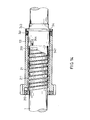
motor 311 drives thethread rod 31, making theshifting gear disk 32 further rotate for another angle to make fiveshift engaging keys shifting gear disk 32. - As shown in Fig.10, the five keys respectively move the driving first, second, third, fourth and fifth
shift slide sleeves shift slide sleeves shift gear sleeves input shaft 1 in same direction. Because the rotating speeds of the driving shift gear sleeves are different from one another, and since inside driving fifth shift gear sleeve, the driving fifth shift spring is twisted on the driving fourth shift gear sleeve and the driving fourth shift spring is twisted on the driving third shift gear sleeve and at the same time, the driving third shift spring is also twisted on the driving second shift gear sleeve and the driving second shift spring is twisted on driving first shift gear sleeve and the driving first shift gear sleeve is twisted on the input shaft, therefore in whole driving shift gear sleeves, the fifth shift gear sleeve has a fastest speed and the fourth one has a second fastest speed, and the third one has a third fastest speed, and the second one has a fourth fastest speed and the first one has a slowest speed. The speeds of input shaft and driving first through fifth shift gear sleeves all are sent to the driven first through fifth shift gear sleeves according to the tooth number ratio between driving and driven shift gear sleeves. Therefore, the driven fifth shift gear sleeve has a fastest speed and since the driven fifth shift gear sleeve is directly engaged with the driven shaft, thus it will transmit directly the sent speed to the driven shaft, and the speeds of driven fourth, third, second and first shift are gradually reduced. Thus, the driven fourth, third, second, first shift springs can not be closely twisted on driven fifth, fourth, third, second shift gear sleeves to form an idling-like state without actual driving. This is fifth shift transmission. The shift number can be increased or reduced according to the same principle. - According to the above description, when the accelerator is stepped down and the power input from engine becomes larger and larger, the data sent from the detecting points to microprocessor also becomes larger and larger,and the instruction sent from the microprocessor to stepped motor also becomes quicker and quicker. Thus, the thread rod will make the shifting gear disk rotate for an angle and another angle, making the engaging keys one by one slide out of the slots to press driving shift slide sleeves to engage with driving shift springs, making the driving shift gear sleeve driven by input shaft and rotate at different speeds which increase from first shift to fifth shift. Therefore, the rotating speed transmitted to the driven shaft also increases gradually and the rotating speed of the output shaft will thus increase gradually.
- However, a common real road condition will not be so smooth and the backing shift is necessary. Thereby, when the data sent to the microprocessor become small to indicate that the accelerator is free or the brake pedal is stepped down and the speed is reduced, the microprocessor will output a signal to stepped motor, making the same reversely rotate to drive the thread rod, making the shifting gear disk rotate reversely, making the engaging keys free from separating force and suffer from a restoring force. The engaging keys will no more press driving shift slide sleeves and the pressed driving shift slide sleeve torque springs will extend to original state. Also, the engaging keys will rebound into the slots of the shifting gear disk,and the driving shift slide sleeve will no more engage with the driving shift springs and rebound to original position, and the driving shift springs also no more be twisted on the driving shift gear sleeve or input shaft and will restore one shift by one shift to also make the driven shift gear sleeves rotate at gradually reduced speed shift by shift. Thus, the neutral state can be achieved. Or, the shift position can be changed to the lower shift and then raised to the higher shift according to external conditions.
- Fig.11-1 shows the sectional view of the advancing/backing/neutral shift controller assembly 7, wherein the neutral shift condition is illustrated. The transmission is connected with an external
manual control lever 71 which is connected with a shiftingdisk 72 and fitted on the drivenshaft 5. The shiftingdisk 72 is fitted on the drivenshaft 5. Two paris of slots are respectively formed on upper and lower sides of the shiftingdisk 72. The outer one is abacking shift slot 721. The upper backing shift slot faces right and the lower one faces left. In the backing shift slot is disposed a backingshift engaging key 731. The size of backing shift slot is about two to three times that of the engaging key. The inner slot is an advancingshift slot 726 which is under thebacking shift slot 721. If the upperbacking shift slot 721 faces left, then the advancingshift slot 726 faces right. Moreover, theslot 726 located under advancing shift is formed above thebacking shift slot 721. If the lowerbacking shift slot 721 faces right, then the advancingshift slot 726 faces left. The size of advancing shift slot is also about two to three times that of engaging key. When in neutral shift state, the manual control lever and advancing shift engaging key and backing shift engaging key are aligned with one another, i.e., the advancing shift and backing shift engaging keys respectively are located in the advancing shift and backing shift slots. Fig. 11-2 shows the advancing/backing/neutral shift controller assembly 7 under backing shift state wherein themanual control lever 71 is turned left for a certain angle, making the backing shift engaging key 731 separate frombacking shift slot 721 and the advancing shift engaging key 736 remain in the advancingshift slot 726 and only move from one end to the other end. Fig. 11-3 shows the controller assembly 7 under advancing shift state. At this time, themanual control lever 71 is turned right for a certain angle, making the advancing shift engaging key 736 separate from the advancingshift slot 726 and the backing shift engaging key 731 remain in thebacking shift slot 721 and only move from one end to the other end. A control button can be used to control the stepped motor and thread rod to drive the advancing/backing shift gear disk to move without using a manual shifting lever. - When under advancing first, third, fifth shift positions as shown in Figs. 6, 8, 10 and when the manual control lever is shifted to the advancing shift position as shown in Fig. 11-3, the advancing shift engaging key 731 slides out of the advancing shift slot toward the advancing
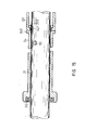
shift slide sleeve 75 of the assembly 7, making the advancing shift slide sleeve slide axially and making the recess thereof engage with the projecting portion of advancingshift spring 811, the rotating speeds of each shift will be transmitted from the driven shaft. The advancing shift spring twisted on the driven shaft will drive the advancing shift gear sleeve to rotate at same speed and in same direction as the driven shaft. Since the advancing shift gear sleeve is screwed on the output shaft, therefore the output shaft will output corresponding to the speed and direction of the driven shaft under each shift position. But the output shaft will rotate in a reverse direction of the rotating direction of the input shaft. Through the output shaft, engine transmits power outwardly to advance. At this time, the backing shift is located in outer layer and not twisted tightly and will not produce any effect. - Fig. 12 shows the transmission under backing shift state, wherein the manual control lever is shifted to the backing position as shown in Fig. 11-2 and the backing shift engaging key 736 slides out of the backing shift slot to press the backing
shift slide sleeve 74 of assembly 7, making the backing shift slide sleeve axially slide to press the backing shift slidesleeve torque spring 741, making the recess of backing shift slide sleeve engage with the projecting portion of thebacking shift spring 821, making the backing shift spring twisted closely on the advancingshift gear sleeve 75 to drive the advancing shift gear sleeve to rotate, and since the advancing shift gear sleeve is screwed on the output shaft, the output shaft is also driven to rotate. The power is obtained in such a manner that the teeth of the backing shift gear sleeve mesh with the teeth of theidle gear 41 and the teeth of idle gear further mesh with the teeth of thebacking gear 40 fitted to theinput shaft 1 so that the backing gear sleeve rotates in same direction as the input shaft and the idle gear rotates in different direction from the input shaft. Therefore, the backing gear sleeve rotates in same direction as the input shaft while the advancing gear sleeve rotates in same direction as the input shaft and the power is transmitted from input shaft toward output shaft to produce a backing effect. The differences between the aforesaid advancing effect and this effect are the power transmitting path and direction and value. Therefore, the advancing and backing shifts are both controlled by manual control lever. When advancing, it will never back up and when backing up, it will never advance to keep the driving smooth and safe. - The housing of this transmission is disposed according to each element. Because it pertains to totally meshing system and is supported by bearings to rotate, the elements all rotate at high speed during a long period, and heat is produced by frictional motion and a lubricating and cooling device is required. In the present invention, an oil pool is disposed under the housing and partial gears are immersed therein so that when rotating, a lubricating and cooling effect is obtained.
- Fig. 13 shows another embodiment of input shaft portion of this invention. A
gear sleeve 21 is fitted on theinput shaft 1. Upper end of thegear sleeve 21 has a gear portion. Thewhole sleeve 21 is integrally made. The gear portion extends beyond the outer surface of thesleeve 21. On inner surface of thegear sleeve 21 is disposed abearing 212. Other end of thesleeve 21 engages with one end of aspring 211. The other end of the spring has a taperedportion 2111 with reduced inner diameter. Aprojection 101 is formed on the input shaft and aslide sleeve 34 is fitted to other end of the input shaft. The slide sleeve has aflange 343. Atorque spring 341 is disposed between the flange and gear sleeve end. A slot is formed on the slide sleeve. The projection 10 is located at one end of the slot. In Fig. 13, the slide sleeve is not forced to slide toward gear sleeve. In Fig. 14, theslide sleeve 34 is forced to slide towardgear sleeve 21 and thetorque spring 341 retracts and theprojection 101 slides in theslot 344 from one end to the other end. At this time, since theprojection 101 engages with the slide sleeve and the input shaft rotates to drive the slide sleeve to rotate, when slide sleeve slides toward the spring, it will engages with thespring 211. The inner rear end of the slide sleeve has a taperedinner surface portion 347 which can more closely engage with the taperedportion 2111 of the spring, making the spring closely twisted on the input shaft to be driven to further retrially drive the gear sleeve. When not forced, the slide sleeve will be rebounded to original position by torque spring. The spring will become loose and no more drive. The outer several gear sleeves are all provided with the projections and same elements. - Fig. 15 shows a further embodiment of the input shaft portion, wherein a
gear sleeve 21 is fitted on theinput shaft 1. The gear sleeve has a gear portion at its one end and is formed integrally. The gear portion extends beyond the outer surface of the gear sleeve. The gear sleeve is provided with abearing 21 near its gear portion end and arecess 215 at its rear end. Aslide sleeve 34 is fitted on the other end of theinput shaft 1. The slide sleeve has projectingportion 345 at its rear end and the input shaft has aprojection 101. Aslot 344 is formed on the slide sleeve to receive theprojection 101 at its one end. At other end of the slide sleeve are disposed twoflanges sleeve neck 347 is received. An engagingkey projecting end 331 can be disposed in the sleeve neck of the slide sleeve to drive the slide sleeve. Fig. 15 shows that the slide sleeve is not engaged with the gear sleeve. - In Fig. 16, the projecting
end 331 of the engaging key drives the slide sleeve to slide toward gear sleeve, making therecess 215 of the gear sleeve engage with projectingportion 345 and the projection of input shaft slide toward the other end. At this time, the input shaft rotates to drive theslide sleeve 34 to rotate and further drive thegear sleeve 21 to rotate. When the projectingend 331 of engaging key is taken back, the slide sleeve slides back too, At this time,only the slide sleeve rotates and no driving effect is produced. The outer several layers are also provided with same elements. - Fig. 17 shows another embodiment of input shaft portion of this invention, wherein a
gear sleeve 21 is fitted on theinput shaft 1 and aspring 211 is disposed whereby when thespring 211 is twisted, the inner diameter thereof is smaller than the outer diameter of the input shaft so that it can be fitted on the input shaft. When the external torque disappears, the resistant restoring torque of the spring will reduce the inner diameter to closely engage with the input shaft. One end of the spring is formed with a triangular projection and one end of thegear sleeve 21 is integrally formed with agear 216. The inner diameter of the gear sleeve is slightly larger than the outer diameters of thespring 211 and slidesleeve 34. Arecess 217 is formed on inner surface near the gear end for a projectingend 212 of the spring to engage with to restrict the spring so that the spring can only perform screwing movement. Moreover, theslide sleeve 34 has a substantially triangular projectingend 348 at its one end and has aannular groove 347 receiving aring member 343 which includes two semicircular members each having aprojection 3431 formed with ahole 3432. Ascrew 3434 goes through theholes 3432 to rotatably fix thering member 343 on theannular groove 347 of theslide sleeve 34. Aprojection 349 is suitable to be placed into aslot 218 of thegear sleeve 21. Each semicircular member has a projectingrod 3433 which is moved by the engaging key. Abearing 212 is further disposed at gear end of the gear sleeve. - Fig. 18 shows that the
ring member 343 is not moved by the engaging key and the triangular projecting end of theslide sleeve 34 engages with the triangular projecting end of the spring to abut against the spring, preventing the same from being twisted closely on theinput shaft 1. At this position, the spring will not drive thegear sleeve 21 to rotate, and the projection of theslide sleeve 34 also engages with theslot 218 to prevent the slide sleeve from rotating. Fig. 19 shows that thering member 343 is outward moved by the engaging key to drive the slide sleeve to outward move, and the projecting end of the slide sleeve no more engages with the projecting end of the spring. At this time, the projection of slide sleeve slides along theslot 218 of gear sleeve from one end toward the other end. At this position, the spring is free from torque and automatically screws tightly on the input shaft to be driven thereby, and since one end of the spring engages with the gear sleeve, the gear sleeve is also driven to rotate and since the slot of the gear sleeve engages with the projection of the slide sleeve, the slide sleeve is also driven to rotate. At this time, the gear sleeve outputs power outwardly. In this embodiment, the aforesaid shifting gear disk of the advancing shift controller operates in reverse directions. The stepped motor outputs power in reverse direction, making the engaging key slide out of the shifting gear disk. When abutting against the ring member, it is neutral shift, and when the engaging key engages with the shifting disk, it is advancing shift, i.e. the original fifth shift effect is now neutral shift and original fourth shift is now first shift and accordingly, the original neutral shift is now fifth shift. The original advancing and backing shifts are now backing and advancing shift. The driving gear set can accordingly form the assembly with several layers. - Having described my invention as related to the embodiment shown in the accompanying drawings, it is my intention that the invention be not limited by any of the details of description, unless otherwise specified, but rather be construed broadly within its spirit and scope as set out in the appended claims.
Claims (27)
Priority Applications (7)
| Application Number | Priority Date | Filing Date | Title |
|---|---|---|---|
| CA 2020582 CA2020582C (en) | 1990-07-23 | 1990-07-06 | Transmission |
| DE1990631036 DE69031036T2 (en) | 1990-07-23 | 1990-07-23 | transmission |
| EP19900308034 EP0468107B1 (en) | 1990-07-23 | 1990-07-23 | Transmission |
| ES90308034T ES2104585T3 (en) | 1990-07-23 | 1990-07-23 | TRANSMISSION. |
| SU4894927/11A RU2058904C1 (en) | 1990-07-23 | 1991-02-04 | Gearbox |
| AU73843/91A AU637469B2 (en) | 1990-07-23 | 1991-03-27 | A transmission |
| PL29051391A PL164496B1 (en) | 1990-07-23 | 1991-06-03 | Automatic gearbox |
Applications Claiming Priority (1)
| Application Number | Priority Date | Filing Date | Title |
|---|---|---|---|
| EP19900308034 EP0468107B1 (en) | 1990-07-23 | 1990-07-23 | Transmission |
Publications (2)
| Publication Number | Publication Date |
|---|---|
| EP0468107A1 true EP0468107A1 (en) | 1992-01-29 |
| EP0468107B1 EP0468107B1 (en) | 1997-07-09 |
Family
ID=8205496
Family Applications (1)
| Application Number | Title | Priority Date | Filing Date |
|---|---|---|---|
| EP19900308034 Expired - Lifetime EP0468107B1 (en) | 1990-07-23 | 1990-07-23 | Transmission |
Country Status (7)
| Country | Link |
|---|---|
| EP (1) | EP0468107B1 (en) |
| AU (1) | AU637469B2 (en) |
| CA (1) | CA2020582C (en) |
| DE (1) | DE69031036T2 (en) |
| ES (1) | ES2104585T3 (en) |
| PL (1) | PL164496B1 (en) |
| RU (1) | RU2058904C1 (en) |
Cited By (4)
| Publication number | Priority date | Publication date | Assignee | Title |
|---|---|---|---|---|
| WO1992021893A1 (en) * | 1991-05-28 | 1992-12-10 | Valery Vladimirovich Dyudin | Gearbox |
| EP0995930A1 (en) * | 1998-10-22 | 2000-04-26 | Sheng-Tsai Tseng | Automobile transmission device |
| CN106763537A (en) * | 2016-12-09 | 2017-05-31 | 李澄 | A kind of novel tower tooth swings decelerator |
| CN107070070A (en) * | 2017-06-13 | 2017-08-18 | 湖北科技学院 | A kind of torque-converting motor |
Families Citing this family (1)
| Publication number | Priority date | Publication date | Assignee | Title |
|---|---|---|---|---|
| RU2584761C2 (en) * | 2014-07-26 | 2016-05-20 | Александр Васильевич Дегтярев | Planetary gearbox with external arrangement of brake coupling |
Citations (7)
| Publication number | Priority date | Publication date | Assignee | Title |
|---|---|---|---|---|
| US1353240A (en) * | 1919-05-07 | 1920-09-21 | George B Ingersoll | Selective change-speed gearing and control mechanism |
| GB335580A (en) * | 1929-06-26 | 1930-09-26 | Erich Moldenhauer | Change speed gear for motor vehicles |
| CH187929A (en) * | 1936-03-17 | 1936-11-30 | Franz Brozincevic & Cie Motorw | Multi-stage manual transmission. |
| US2086563A (en) * | 1934-12-22 | 1937-07-13 | Ollie Reese | Change speed transmission |
| GB486567A (en) * | 1936-12-04 | 1938-06-07 | Armstrong Siddeley Motors Ltd | Constant-mesh gear-box |
| GB2205366A (en) * | 1987-06-02 | 1988-12-07 | Ricardo Consulting Eng | Automatic gearboxes having centrifugal clutches |
| EP0240901B1 (en) * | 1986-04-11 | 1990-09-26 | Eaton Corporation | Transmission shift control system |
Family Cites Families (2)
| Publication number | Priority date | Publication date | Assignee | Title |
|---|---|---|---|---|
| DE3913091A1 (en) * | 1989-04-21 | 1990-10-25 | Porsche Ag | GEARBOX TRANSMISSION FOR A MOTOR VEHICLE |
| US4966574A (en) * | 1989-06-06 | 1990-10-30 | Tecumseh Products Company | Transaxle |
-
1990
- 1990-07-06 CA CA 2020582 patent/CA2020582C/en not_active Expired - Fee Related
- 1990-07-23 DE DE1990631036 patent/DE69031036T2/en not_active Expired - Fee Related
- 1990-07-23 ES ES90308034T patent/ES2104585T3/en not_active Expired - Lifetime
- 1990-07-23 EP EP19900308034 patent/EP0468107B1/en not_active Expired - Lifetime
-
1991
- 1991-02-04 RU SU4894927/11A patent/RU2058904C1/en not_active IP Right Cessation
- 1991-03-27 AU AU73843/91A patent/AU637469B2/en not_active Ceased
- 1991-06-03 PL PL29051391A patent/PL164496B1/en not_active IP Right Cessation
Patent Citations (7)
| Publication number | Priority date | Publication date | Assignee | Title |
|---|---|---|---|---|
| US1353240A (en) * | 1919-05-07 | 1920-09-21 | George B Ingersoll | Selective change-speed gearing and control mechanism |
| GB335580A (en) * | 1929-06-26 | 1930-09-26 | Erich Moldenhauer | Change speed gear for motor vehicles |
| US2086563A (en) * | 1934-12-22 | 1937-07-13 | Ollie Reese | Change speed transmission |
| CH187929A (en) * | 1936-03-17 | 1936-11-30 | Franz Brozincevic & Cie Motorw | Multi-stage manual transmission. |
| GB486567A (en) * | 1936-12-04 | 1938-06-07 | Armstrong Siddeley Motors Ltd | Constant-mesh gear-box |
| EP0240901B1 (en) * | 1986-04-11 | 1990-09-26 | Eaton Corporation | Transmission shift control system |
| GB2205366A (en) * | 1987-06-02 | 1988-12-07 | Ricardo Consulting Eng | Automatic gearboxes having centrifugal clutches |
Cited By (5)
| Publication number | Priority date | Publication date | Assignee | Title |
|---|---|---|---|---|
| WO1992021893A1 (en) * | 1991-05-28 | 1992-12-10 | Valery Vladimirovich Dyudin | Gearbox |
| EP0995930A1 (en) * | 1998-10-22 | 2000-04-26 | Sheng-Tsai Tseng | Automobile transmission device |
| CN106763537A (en) * | 2016-12-09 | 2017-05-31 | 李澄 | A kind of novel tower tooth swings decelerator |
| CN107070070A (en) * | 2017-06-13 | 2017-08-18 | 湖北科技学院 | A kind of torque-converting motor |
| CN107070070B (en) * | 2017-06-13 | 2023-04-14 | 湖北科技学院 | Torque-variable motor |
Also Published As
| Publication number | Publication date |
|---|---|
| EP0468107B1 (en) | 1997-07-09 |
| AU7384391A (en) | 1992-03-05 |
| PL290513A1 (en) | 1992-06-26 |
| DE69031036T2 (en) | 1997-10-30 |
| CA2020582C (en) | 1994-04-05 |
| AU637469B2 (en) | 1993-05-27 |
| ES2104585T3 (en) | 1997-10-16 |
| RU2058904C1 (en) | 1996-04-27 |
| DE69031036D1 (en) | 1997-08-14 |
| CA2020582A1 (en) | 1992-01-07 |
| PL164496B1 (en) | 1994-08-31 |
Similar Documents
| Publication | Publication Date | Title |
|---|---|---|
| US4541821A (en) | V-belt type stepless transmission | |
| JPS58184345A (en) | Speed change gear for car | |
| KR890005426A (en) | Split type compound transmission with increased speed | |
| US5004082A (en) | Starting device of an automatic transmission for vehicle | |
| US10525817B2 (en) | Supplemental transmission assembly | |
| US2889716A (en) | Variable and reversing power transmission | |
| US5000057A (en) | Fully engaged transmission | |
| US4858492A (en) | Power transmission system | |
| EP0468107A1 (en) | Transmission | |
| EP0248563B1 (en) | Drive transmission apparatus | |
| JPS6026844A (en) | V-belt type stepless speed change gear | |
| EP0321509A1 (en) | Automatic transmission | |
| EP0931228B1 (en) | An actuating device for a continuously variable transmission | |
| KR950010095B1 (en) | Speed changer | |
| EP0151037B1 (en) | System for controlling the clutch current of an electromagnetic clutch for a vehicle | |
| JPH03204443A (en) | Control system for continuously variable transmission | |
| GB2177765A (en) | Improvements relating to automatic transmission systems | |
| JPH0647350B2 (en) | Continuously variable transmission for automobiles | |
| CN2811680Y (en) | Electrically-controlled stepped mechanical automatic transmission | |
| USRE20846E (en) | Variable speed transmission | |
| KR970003561B1 (en) | Clutch combined with a transmission device | |
| JPH0326292B2 (en) | ||
| RU2170368C1 (en) | Submerged screw pump surface drive | |
| JP3206391B2 (en) | Transmission | |
| KR0168385B1 (en) | Cvt for a vehicle |
Legal Events
| Date | Code | Title | Description |
|---|---|---|---|
| PUAI | Public reference made under article 153(3) epc to a published international application that has entered the european phase |
Free format text: ORIGINAL CODE: 0009012 |
|
| AK | Designated contracting states |
Kind code of ref document: A1 Designated state(s): DE ES FR GB IT |
|
| 17P | Request for examination filed |
Effective date: 19920630 |
|
| 17Q | First examination report despatched |
Effective date: 19940117 |
|
| GRAG | Despatch of communication of intention to grant |
Free format text: ORIGINAL CODE: EPIDOS AGRA |
|
| GRAH | Despatch of communication of intention to grant a patent |
Free format text: ORIGINAL CODE: EPIDOS IGRA |
|
| GRAH | Despatch of communication of intention to grant a patent |
Free format text: ORIGINAL CODE: EPIDOS IGRA |
|
| GRAH | Despatch of communication of intention to grant a patent |
Free format text: ORIGINAL CODE: EPIDOS IGRA |
|
| GRAA | (expected) grant |
Free format text: ORIGINAL CODE: 0009210 |
|
| AK | Designated contracting states |
Kind code of ref document: B1 Designated state(s): DE ES FR GB IT |
|
| PGFP | Annual fee paid to national office [announced via postgrant information from national office to epo] |
Ref country code: ES Payment date: 19970717 Year of fee payment: 8 |
|
| PGFP | Annual fee paid to national office [announced via postgrant information from national office to epo] |
Ref country code: FR Payment date: 19970729 Year of fee payment: 8 |
|
| ET | Fr: translation filed | ||
| REF | Corresponds to: |
Ref document number: 69031036 Country of ref document: DE Date of ref document: 19970814 |
|
| REG | Reference to a national code |
Ref country code: ES Ref legal event code: FG2A Ref document number: 2104585 Country of ref document: ES Kind code of ref document: T3 |
|
| PLBE | No opposition filed within time limit |
Free format text: ORIGINAL CODE: 0009261 |
|
| STAA | Information on the status of an ep patent application or granted ep patent |
Free format text: STATUS: NO OPPOSITION FILED WITHIN TIME LIMIT |
|
| 26N | No opposition filed | ||
| PG25 | Lapsed in a contracting state [announced via postgrant information from national office to epo] |
Ref country code: ES Free format text: LAPSE BECAUSE OF NON-PAYMENT OF DUE FEES Effective date: 19980724 |
|
| GBPC | Gb: european patent ceased through non-payment of renewal fee |
Effective date: 19980723 |
|
| PG25 | Lapsed in a contracting state [announced via postgrant information from national office to epo] |
Ref country code: FR Free format text: LAPSE BECAUSE OF NON-PAYMENT OF DUE FEES Effective date: 19990331 |
|
| REG | Reference to a national code |
Ref country code: FR Ref legal event code: ST |
|
| REG | Reference to a national code |
Ref country code: GB Ref legal event code: 728V |
|
| REG | Reference to a national code |
Ref country code: GB Ref legal event code: 728Y |
|
| REG | Reference to a national code |
Ref country code: GB Ref legal event code: IF02 |
|
| PGFP | Annual fee paid to national office [announced via postgrant information from national office to epo] |
Ref country code: GB Payment date: 20030711 Year of fee payment: 14 |
|
| PGFP | Annual fee paid to national office [announced via postgrant information from national office to epo] |
Ref country code: DE Payment date: 20030729 Year of fee payment: 14 |
|
| REG | Reference to a national code |
Ref country code: ES Ref legal event code: FD2A Effective date: 19990811 |
|
| PG25 | Lapsed in a contracting state [announced via postgrant information from national office to epo] |
Ref country code: GB Free format text: LAPSE BECAUSE OF NON-PAYMENT OF DUE FEES Effective date: 20040723 |
|
| PG25 | Lapsed in a contracting state [announced via postgrant information from national office to epo] |
Ref country code: DE Free format text: LAPSE BECAUSE OF NON-PAYMENT OF DUE FEES Effective date: 20050201 |
|
| GBPC | Gb: european patent ceased through non-payment of renewal fee |
Effective date: 20040723 |
|
| PG25 | Lapsed in a contracting state [announced via postgrant information from national office to epo] |
Ref country code: IT Free format text: LAPSE BECAUSE OF NON-PAYMENT OF DUE FEES;WARNING: LAPSES OF ITALIAN PATENTS WITH EFFECTIVE DATE BEFORE 2007 MAY HAVE OCCURRED AT ANY TIME BEFORE 2007. THE CORRECT EFFECTIVE DATE MAY BE DIFFERENT FROM THE ONE RECORDED. Effective date: 20050723 |