EP0467995B1 - An arrangement in fume extraction arms - Google Patents
An arrangement in fume extraction arms Download PDFInfo
- Publication number
- EP0467995B1 EP0467995B1 EP90908100A EP90908100A EP0467995B1 EP 0467995 B1 EP0467995 B1 EP 0467995B1 EP 90908100 A EP90908100 A EP 90908100A EP 90908100 A EP90908100 A EP 90908100A EP 0467995 B1 EP0467995 B1 EP 0467995B1
- Authority
- EP
- European Patent Office
- Prior art keywords
- joint
- bolt
- leg members
- members
- leg
- Prior art date
- Legal status (The legal status is an assumption and is not a legal conclusion. Google has not performed a legal analysis and makes no representation as to the accuracy of the status listed.)
- Expired - Lifetime
Links
- 238000000605 extraction Methods 0.000 title claims abstract description 15
- 239000003517 fume Substances 0.000 title description 5
- 210000001503 joint Anatomy 0.000 claims abstract description 14
- 239000002184 metal Substances 0.000 claims description 4
- 239000007789 gas Substances 0.000 description 1
- 230000008407 joint function Effects 0.000 description 1
- 238000005461 lubrication Methods 0.000 description 1
- 238000000034 method Methods 0.000 description 1
- 239000003921 oil Substances 0.000 description 1
Images

Classifications
-
- B—PERFORMING OPERATIONS; TRANSPORTING
- B08—CLEANING
- B08B—CLEANING IN GENERAL; PREVENTION OF FOULING IN GENERAL
- B08B15/00—Preventing escape of dirt or fumes from the area where they are produced; Collecting or removing dirt or fumes from that area
- B08B15/002—Preventing escape of dirt or fumes from the area where they are produced; Collecting or removing dirt or fumes from that area using a central suction system, e.g. for collecting exhaust gases in workshops
-
- F—MECHANICAL ENGINEERING; LIGHTING; HEATING; WEAPONS; BLASTING
- F16—ENGINEERING ELEMENTS AND UNITS; GENERAL MEASURES FOR PRODUCING AND MAINTAINING EFFECTIVE FUNCTIONING OF MACHINES OR INSTALLATIONS; THERMAL INSULATION IN GENERAL
- F16L—PIPES; JOINTS OR FITTINGS FOR PIPES; SUPPORTS FOR PIPES, CABLES OR PROTECTIVE TUBING; MEANS FOR THERMAL INSULATION IN GENERAL
- F16L27/00—Adjustable joints; Joints allowing movement
- F16L27/08—Adjustable joints; Joints allowing movement allowing adjustment or movement only about the axis of one pipe
- F16L27/0849—Adjustable joints; Joints allowing movement allowing adjustment or movement only about the axis of one pipe the fluid being turned through an angle when passing from one joint element to another
- F16L27/0857—Adjustable joints; Joints allowing movement allowing adjustment or movement only about the axis of one pipe the fluid being turned through an angle when passing from one joint element to another with hinge and bellows sealing
Definitions
- the subject invention concerns generally, an arrangement in fume extraction arms and more precisely an external middle joint for an extraction arm according to the first part of the single independent claim.
- Such a joint is known from SE-B-424 409.
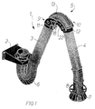
- the extraction arm illustrated in FIG. 1 and generally designated by numeral reference 1 is primarily intended for localized extraction of fumes, gas, oil mists and similar exhaust fumes.
- the main components of the extraction arm is a wall attachment 2 on which is mounted a motor-operated extraction fan, not shown.
- the arm 1 further comprises an inner arm 3 and an outer arm 4 made from smooth metal tubing and the arms 3, 4 are interconnected by means of a middle joint in accordance with the invention, generally designated by numeral reference 5.
- a flexible tube 6 extends between the inner arm 3 and the attachement 2 and at the free end of the outer arm 4 there is provided an extraction hood 7 and a ring-shaped operating handle 8 by means of which the extraction hood 7 and consequently the entire extraction arm assembly may be moved to the desired position.
- the middle joint 5 illustrated in closer detail in FIG. 2 is of the external type, i.e. it is positioned externally of the inner and outer arms 3 and 4 and it comprises two essentially identical halves 9 and 10 which in accordance with the embodiment illustrated are made from sheet metal.
- One of the joint halves 9 is connected to the outer end of the tubular inner arm 3 whereas the other joint half 10 is connected to the inner end of the tubular outer arm 4, more precisely with the aid of connecting pieces 11, 12 designed to be applied in a tight position about their respective arm end.
- a flexible piece of hose 13, see FIG. 1 extends between the two arm ends, whereby a continous fume extraction channel is formed, extending from the extraction hood 7 to the suction fan, not shown.
- Each joint half 9 and 10 is formed with two leg members 14, 15 and 16, 17, respectively, which project from the associated connection piece 11 and 12 so as to extend on either side of the piece of hose 13.
- the leg members are formed from flat sheet metal plates having through-holes formed therein and they have an arcuate configuration, tapering towards their free ends.
- each leg member 14, 15 and 16, 17, respectively is articulated to a corresponding leg member of the other joint half by means of bolt connections 18 and 19 to be described in closer detail in the following.
- these bolt connections 18, 19 consist of a bolt 20 which is non-rotationally attached to one of the leg members 14 and 17, respectively, of each joint half 9 and 10.
- the bolts 20 extend with some play through the opposite leg member 16 and 15, respectively, of the other joint half 10 and 9, respectively, and at their free ends they support a knob 21 which is screwed onto an associated bolt 20.
- the bolt connections which consist of bolts corresponding to bolts 20 and which are non-rotationally mounted in both leg members 14 and 15 or 16 and 17 of one of the joint halves 9 or 10. These bolts extend with some play through the two leg members 16, 17 or 14, 15 of the other joint half 10 or 9 and at their free ends these bolts support a knob corresponding to knob 21 which is threaded onto its associated bolt.
- the bolts 20 are carriage bolts which are non-rotationally mounted in square apertures, not shown, which are formed in the leg members.
- the knobs 21 on these bolts 20 preferably are in the shape of wheels formed with hand gripping surfaces.
- a driving member 22 and 23 is mounted intermediate the associated knob 21 and that face 24 of the adjacent leg member which is turned towards said driving members, in accordance with drawing figure 2 leg member 15 and leg member 16.
- Each knob 21 may be screwed towards or from its associated one of driving members 22 and 23 to adjust the movability of the middle joint 5 and each driving member 22 and 23 is anchored in the leg member - in accordance with figure 2 leg member 17 and 14 - to which the bolt 20 is non-rotationally attached.
- the driving members 22, 23 and consequently the knobs 21 thus will be imparted a movement identical to that of the associated bolt 20, whereby automatic unscrewing movements of the bolt connections 18 and 19 are prevented.
- the bolt connections as such thus will behave as if they were screwed into one single plate instead of to a movable middle joint.
- the driving members are in the shape of elongate plates which are formed at one of their ends with an aperture, not shown, for application of this plate end onto the associated bolt 20 intermediate the knob 21 and the leg member face 24 mentioned above, whereas the opposite plate end is bent inwards and is inserted in a slot 25 formed in the leg member, as explained in the aforegoing either leg member 17 or 14, in which the bolts 20 are non-rotationally mounted.
Landscapes
- Engineering & Computer Science (AREA)
- General Engineering & Computer Science (AREA)
- Mechanical Engineering (AREA)
- Manipulator (AREA)
- Toys (AREA)
- Extraction Or Liquid Replacement (AREA)
- Quick-Acting Or Multi-Walled Pipe Joints (AREA)
- Mutual Connection Of Rods And Tubes (AREA)
- Filtering Materials (AREA)
- Respiratory Apparatuses And Protective Means (AREA)
- Professional, Industrial, Or Sporting Protective Garments (AREA)
- Meat, Egg Or Seafood Products (AREA)
Abstract
Description
- The subject invention concerns generally, an arrangement in fume extraction arms and more precisely an external middle joint for an extraction arm according to the first part of the single independent claim. Such a joint is known from SE-B-424 409.
- One problem found in bolt connections comprising a movable joint is that in general they have an inherent tendency to unscrew automatically. If brake linings are used in the joint to maintain the friction at a constant level (constant joint movability), such unscrewing of the bolts of the joint must not occur since this would mean loss of the joint function.
- One common method of solving this problem is to mount two needle bearings on each bolt connection in order to prevent self-unscrewing tendencies. This arrangement cannot, however, provide full security because of the difficulty in supplying lubrication to the bearings, with the result that the latter may seize and cause looseness in the joint.
- In order to eliminate this problem the subject invention proposes a novel and simple, yet efficient means, according to the characterising features of the patent claim.
- The invention will be described in closer detail in the following with reference to the accompanying drawings, wherein:
- FIG. 1 illustrates an almost complete extraction arm in a perspective view from above, provided with a middle joint in accordance with the invention; and
- FIG. 2 illustrates the middle joint in accordance with the invention separately in a perspective view obliquely from below.
- The extraction arm illustrated in FIG. 1 and generally designated by numeral reference 1 is primarily intended for localized extraction of fumes, gas, oil mists and similar exhaust fumes. The main components of the extraction arm is a
wall attachment 2 on which is mounted a motor-operated extraction fan, not shown. The arm 1 further comprises aninner arm 3 and an outer arm 4 made from smooth metal tubing and thearms 3, 4 are interconnected by means of a middle joint in accordance with the invention, generally designated by numeral reference 5. Aflexible tube 6 extends between theinner arm 3 and theattachement 2 and at the free end of the outer arm 4 there is provided anextraction hood 7 and a ring-shaped operating handle 8 by means of which the extraction hood 7 and consequently the entire extraction arm assembly may be moved to the desired position. - The middle joint 5 illustrated in closer detail in FIG. 2 is of the external type, i.e. it is positioned externally of the inner and
outer arms 3 and 4 and it comprises two essentiallyidentical halves joint halves 9 is connected to the outer end of the tubularinner arm 3 whereas the otherjoint half 10 is connected to the inner end of the tubular outer arm 4, more precisely with the aid of connectingpieces hose 13, see FIG. 1 extends between the two arm ends, whereby a continous fume extraction channel is formed, extending from theextraction hood 7 to the suction fan, not shown. - Each
joint half leg members connection piece hose 13. In accordance with the embodiment illustrated in the drawings the leg members are formed from flat sheet metal plates having through-holes formed therein and they have an arcuate configuration, tapering towards their free ends. At its outer free ends eachleg member bolt connections - In accordance with the embodiment illustrated in the drawings, these
bolt connections bolt 20 which is non-rotationally attached to one of theleg members joint half bolts 20 extend with some play through theopposite leg member joint half knob 21 which is screwed onto an associatedbolt 20. - In accordance with an alternative embodiment, not illustrated, the bolt connections which consist of bolts corresponding to
bolts 20 and which are non-rotationally mounted in bothleg members joint halves leg members joint half knob 21 which is threaded onto its associated bolt. - In accordance with both embodiments the
bolts 20 are carriage bolts which are non-rotationally mounted in square apertures, not shown, which are formed in the leg members. Theknobs 21 on thesebolts 20 preferably are in the shape of wheels formed with hand gripping surfaces. - As appears from the drawings, a
driving member knob 21 and thatface 24 of the adjacent leg member which is turned towards said driving members, in accordance with drawing figure 2leg member 15 andleg member 16. Eachknob 21 may be screwed towards or from its associated one of drivingmembers driving member leg member 17 and 14 - to which thebolt 20 is non-rotationally attached. Upon angular movements of the middle joint 5, the drivingmembers knobs 21 thus will be imparted a movement identical to that of the associatedbolt 20, whereby automatic unscrewing movements of thebolt connections - In accordance with the embodiment illustrated in the drawings the driving members are in the shape of elongate plates which are formed at one of their ends with an aperture, not shown, for application of this plate end onto the associated
bolt 20 intermediate theknob 21 and theleg member face 24 mentioned above, whereas the opposite plate end is bent inwards and is inserted in aslot 25 formed in the leg member, as explained in the aforegoing eitherleg member bolts 20 are non-rotationally mounted.
Claims (1)
- An external adjustable middle joint (5) for an extraction arm (1), said middle joint comprising two halves (9, 10), one (9) of which is connected to one end of an inner tubular arm (3) and the other half (10) of which is connected to one end of an outer tubular arm (4) by means of their respective one of connection pieces (11, 12), a length of flexible hose (13) extending between and interconnecting said ends of the tubular arms (3, 4), each joint half (9, 10) having two leg members (14, 15 and 16, 17, respectively) projecting from the corresponding arm connection piece (11, 12) so as to extend alongside the length of hose (13) on either side thereof, the outer free ends of the leg members of one joint half (9 or 10) being articulated to the corresponding opposite outer free ends of the leg members of the other joint half (9 or 10) by means of bolt connections (18, 19) comprising either a bolt (20) which is non-rotationally mounted in one (14 and 17, respectively) of the two leg members of each joint half (9, 10) and which with play extends through the opposite one of the two leg members (16 and 15, respectively) of the other half (10 and 9, respectively) of the joint and which bolt supports at its outer free end a tightening means (21) which is threaded onto said bolt, or bolts (20) which are non-rotationally mounted in both leg members (14, 15) of one of the joint halves (9 or 10) and with play extend through the two leg members (16, 17 or 14, 15) of the opposite joint half (10 or 9), each bolt supporting at its outer free end a tightening means (21) which is threaded onto said bolt, a driving member (22 and 23, respectively) being mounted in a position intermediate the corresponding tightening means (21) and the face (24) of the adjacent leg member (15 and 16, respectively) that is turned towards said driving member (22 and 23, respectively), said tightening means (21) being arranged to be screwed into a position against said driving member (21) in order to adjust the movability of the middle joint (5), characterized in that both leg members (14, 15 and 16, 17) of both joint halves (9, 10) are made from flat sheet metal plates having an arcuate configuration tapering towards the outer free ends of the leg members, in that the tightening means are in the form of wheels (21) having gripping surfaces thereon, and in that the driving members (22, 23) are anchored in those leg members (17 and 14, respectively) in which the bolts in the form of carriage bolts (20) are non-rotationally mounted in square apertures formed in said one leg member of each joint half (9, 10), said driving members being in the form of elongate plates which are formed at one of their ends with an aperture for application on the associated carriage bolt (20) in a position intermediate the wheel (21) and said face (24), and which plates are bent at their opposite end and inserted by means of said end in their respectively one of slits (25) formed in the leg members (17 and 14, respectively) in which the carriage bolts (20) are non-rotationally mounted, whereby upon pivotal movement of the middle joint (5) said driving members (22, 23) and consequently the wheels (21) will be given a motion identical with that of the associated carriage bolts (20), thus preventing the inherent unscrewing tendency of the bolt connections (18, 19).
Priority Applications (1)
| Application Number | Priority Date | Filing Date | Title |
|---|---|---|---|
| AT90908100T ATE108100T1 (en) | 1989-04-13 | 1990-04-17 | ARRANGEMENT IN SMOKE EXTRACTION TUBE. |
Applications Claiming Priority (3)
| Application Number | Priority Date | Filing Date | Title |
|---|---|---|---|
| SE8901331A SE8901331D0 (en) | 1989-04-13 | 1989-04-13 | DEVICE ARM DEVICE |
| SE8901331 | 1989-04-13 | ||
| PCT/SE1990/000254 WO1990011845A1 (en) | 1989-04-13 | 1990-04-17 | An arrangement in fume extraction arms |
Publications (2)
| Publication Number | Publication Date |
|---|---|
| EP0467995A1 EP0467995A1 (en) | 1992-01-29 |
| EP0467995B1 true EP0467995B1 (en) | 1994-07-06 |
Family
ID=20375661
Family Applications (1)
| Application Number | Title | Priority Date | Filing Date |
|---|---|---|---|
| EP90908100A Expired - Lifetime EP0467995B1 (en) | 1989-04-13 | 1990-04-17 | An arrangement in fume extraction arms |
Country Status (8)
| Country | Link |
|---|---|
| EP (1) | EP0467995B1 (en) |
| AT (1) | ATE108100T1 (en) |
| AU (1) | AU5530790A (en) |
| DE (1) | DE69010493T2 (en) |
| DK (1) | DK0467995T3 (en) |
| ES (1) | ES2060169T3 (en) |
| SE (1) | SE8901331D0 (en) |
| WO (1) | WO1990011845A1 (en) |
Families Citing this family (4)
| Publication number | Priority date | Publication date | Assignee | Title |
|---|---|---|---|---|
| US5156697A (en) * | 1989-09-05 | 1992-10-20 | Board Of Regents, The University Of Texas System | Selective laser sintering of parts by compound formation of precursor powders |
| US5951725A (en) * | 1995-06-07 | 1999-09-14 | National Tool And Equipment, Inc. | System for removal of noxious fumes |
| EP2995387A3 (en) * | 2014-09-12 | 2016-06-29 | Filcar S.p.A. | A telescopic extraction arm |
| CN109719106A (en) * | 2019-01-18 | 2019-05-07 | 江苏久华环保科技股份有限公司 | A kind of steel plant's house dust absorption plant |
Family Cites Families (2)
| Publication number | Priority date | Publication date | Assignee | Title |
|---|---|---|---|---|
| GB512175A (en) * | 1938-05-16 | 1939-08-30 | John Dugdill & Company Ltd | Improvements in or relating to joints for tubes |
| SE424409B (en) * | 1975-12-04 | 1982-07-19 | Coral Sas | DEVICE FOR LOCAL EXTENSION OF GASES, Fumes AND SIMILAR |
-
1989
- 1989-04-13 SE SE8901331A patent/SE8901331D0/en unknown
-
1990
- 1990-04-17 DE DE69010493T patent/DE69010493T2/en not_active Expired - Fee Related
- 1990-04-17 ES ES90908100T patent/ES2060169T3/en not_active Expired - Lifetime
- 1990-04-17 AU AU55307/90A patent/AU5530790A/en not_active Abandoned
- 1990-04-17 WO PCT/SE1990/000254 patent/WO1990011845A1/en active IP Right Grant
- 1990-04-17 DK DK90908100.2T patent/DK0467995T3/en active
- 1990-04-17 AT AT90908100T patent/ATE108100T1/en not_active IP Right Cessation
- 1990-04-17 EP EP90908100A patent/EP0467995B1/en not_active Expired - Lifetime
Also Published As
| Publication number | Publication date |
|---|---|
| ATE108100T1 (en) | 1994-07-15 |
| DE69010493T2 (en) | 1995-02-23 |
| AU5530790A (en) | 1990-11-05 |
| DE69010493D1 (en) | 1994-08-11 |
| EP0467995A1 (en) | 1992-01-29 |
| DK0467995T3 (en) | 1994-11-07 |
| ES2060169T3 (en) | 1994-11-16 |
| SE8901331D0 (en) | 1989-04-13 |
| WO1990011845A1 (en) | 1990-10-18 |
Similar Documents
| Publication | Publication Date | Title |
|---|---|---|
| US5211602A (en) | Arrangement in fume extraction arms | |
| US4860644A (en) | Articulatable fume exhauster trunk | |
| USD347467S (en) | Sleeve for a quick connect fluid coupling | |
| DE69423789D1 (en) | FLOW CONTROL DEVICE FOR THE COMPRESSOR PART OF A FLUID MACHINE | |
| US4898490A (en) | Structure formed from ball jointed links | |
| CA2034332A1 (en) | Drive system for impeller shafts | |
| EP0467995B1 (en) | An arrangement in fume extraction arms | |
| ATE153427T1 (en) | CONNECTION BETWEEN A ROTARY OR SWIVEL FITTING AND A ROTARY ACTUATOR | |
| ES2125691T3 (en) | FURNITURE FOR FURNITURE. | |
| YU188485A (en) | Console girder for dentist's room | |
| US5527217A (en) | Adjustable device for exhaustion and/or supply of gas | |
| DE2634990C3 (en) | Radiator mounting for motor vehicles | |
| CA2051101C (en) | Arrangement in fume extraction arms | |
| USD363115S (en) | Component part of a T-piece | |
| KR970059556A (en) | Tube Coupling Lock | |
| US6082702A (en) | Tubing pinch valve and mounting bracket assembly | |
| ATE339644T1 (en) | FLANGE MEMBER HAVING A FIRST FLANGE END DESIGNED WITH A CONCAVE END SURFACE IN A RADIAL DIRECTION AND A FLANGE CONNECTION COMPRISING FLANGE LINKS | |
| SE8400537D0 (en) | KREUZGELENKWELLE | |
| GB2113818A (en) | Flexible arm light fittings | |
| BG101299A (en) | Housing for a support shoe in a trench falsework | |
| EP0628735A1 (en) | Releasable connection for an office furnishing | |
| ATE21159T1 (en) | CLAMP. | |
| CA2152661A1 (en) | Improved disengaging means for hose couplings | |
| DK0786614T3 (en) | Sanitary valve | |
| ES8300183A1 (en) | Joints between tubular members |
Legal Events
| Date | Code | Title | Description |
|---|---|---|---|
| PUAI | Public reference made under article 153(3) epc to a published international application that has entered the european phase |
Free format text: ORIGINAL CODE: 0009012 |
|
| 17P | Request for examination filed |
Effective date: 19911008 |
|
| AK | Designated contracting states |
Kind code of ref document: A1 Designated state(s): AT BE CH DE DK ES FR GB IT LI LU NL SE |
|
| 17Q | First examination report despatched |
Effective date: 19930519 |
|
| GRAA | (expected) grant |
Free format text: ORIGINAL CODE: 0009210 |
|
| AK | Designated contracting states |
Kind code of ref document: B1 Designated state(s): AT BE CH DE DK ES FR GB IT LI LU NL SE |
|
| REF | Corresponds to: |
Ref document number: 108100 Country of ref document: AT Date of ref document: 19940715 Kind code of ref document: T |
|
| REF | Corresponds to: |
Ref document number: 69010493 Country of ref document: DE Date of ref document: 19940811 |
|
| ITF | It: translation for a ep patent filed | ||
| ET | Fr: translation filed | ||
| REG | Reference to a national code |
Ref country code: DK Ref legal event code: T3 |
|
| REG | Reference to a national code |
Ref country code: ES Ref legal event code: FG2A Ref document number: 2060169 Country of ref document: ES Kind code of ref document: T3 |
|
| EAL | Se: european patent in force in sweden |
Ref document number: 90908100.2 |
|
| PG25 | Lapsed in a contracting state [announced via postgrant information from national office to epo] |
Ref country code: LU Free format text: LAPSE BECAUSE OF NON-PAYMENT OF DUE FEES Effective date: 19950430 |
|
| PLBE | No opposition filed within time limit |
Free format text: ORIGINAL CODE: 0009261 |
|
| STAA | Information on the status of an ep patent application or granted ep patent |
Free format text: STATUS: NO OPPOSITION FILED WITHIN TIME LIMIT |
|
| 26N | No opposition filed | ||
| PGFP | Annual fee paid to national office [announced via postgrant information from national office to epo] |
Ref country code: AT Payment date: 19980225 Year of fee payment: 9 |
|
| PGFP | Annual fee paid to national office [announced via postgrant information from national office to epo] |
Ref country code: BE Payment date: 19980304 Year of fee payment: 9 |
|
| PGFP | Annual fee paid to national office [announced via postgrant information from national office to epo] |
Ref country code: ES Payment date: 19980408 Year of fee payment: 9 |
|
| PGFP | Annual fee paid to national office [announced via postgrant information from national office to epo] |
Ref country code: CH Payment date: 19980731 Year of fee payment: 9 |
|
| PG25 | Lapsed in a contracting state [announced via postgrant information from national office to epo] |
Ref country code: AT Free format text: LAPSE BECAUSE OF NON-PAYMENT OF DUE FEES Effective date: 19990417 |
|
| PG25 | Lapsed in a contracting state [announced via postgrant information from national office to epo] |
Ref country code: ES Free format text: LAPSE BECAUSE OF NON-PAYMENT OF DUE FEES Effective date: 19990419 |
|
| PG25 | Lapsed in a contracting state [announced via postgrant information from national office to epo] |
Ref country code: BE Free format text: LAPSE BECAUSE OF NON-PAYMENT OF DUE FEES Effective date: 19990430 Ref country code: CH Free format text: LAPSE BECAUSE OF NON-PAYMENT OF DUE FEES Effective date: 19990430 Ref country code: LI Free format text: LAPSE BECAUSE OF NON-PAYMENT OF DUE FEES Effective date: 19990430 |
|
| BERE | Be: lapsed |
Owner name: J H PLYMOTH A.B. Effective date: 19990430 |
|
| REG | Reference to a national code |
Ref country code: CH Ref legal event code: PL |
|
| REG | Reference to a national code |
Ref country code: ES Ref legal event code: FD2A Effective date: 20010503 |
|
| REG | Reference to a national code |
Ref country code: GB Ref legal event code: IF02 |
|
| PGFP | Annual fee paid to national office [announced via postgrant information from national office to epo] |
Ref country code: SE Payment date: 20050615 Year of fee payment: 16 |
|
| PGFP | Annual fee paid to national office [announced via postgrant information from national office to epo] |
Ref country code: DE Payment date: 20050623 Year of fee payment: 16 Ref country code: NL Payment date: 20050623 Year of fee payment: 16 |
|
| PGFP | Annual fee paid to national office [announced via postgrant information from national office to epo] |
Ref country code: GB Payment date: 20050926 Year of fee payment: 16 |
|
| PGFP | Annual fee paid to national office [announced via postgrant information from national office to epo] |
Ref country code: DK Payment date: 20051026 Year of fee payment: 16 |
|
| PGFP | Annual fee paid to national office [announced via postgrant information from national office to epo] |
Ref country code: FR Payment date: 20051028 Year of fee payment: 16 |
|
| PG25 | Lapsed in a contracting state [announced via postgrant information from national office to epo] |
Ref country code: GB Free format text: LAPSE BECAUSE OF NON-PAYMENT OF DUE FEES Effective date: 20060417 |
|
| PG25 | Lapsed in a contracting state [announced via postgrant information from national office to epo] |
Ref country code: SE Free format text: LAPSE BECAUSE OF NON-PAYMENT OF DUE FEES Effective date: 20060418 |
|
| PGFP | Annual fee paid to national office [announced via postgrant information from national office to epo] |
Ref country code: IT Payment date: 20060430 Year of fee payment: 17 |
|
| PG25 | Lapsed in a contracting state [announced via postgrant information from national office to epo] |
Ref country code: DK Free format text: LAPSE BECAUSE OF NON-PAYMENT OF DUE FEES Effective date: 20060501 |
|
| PG25 | Lapsed in a contracting state [announced via postgrant information from national office to epo] |
Ref country code: NL Free format text: LAPSE BECAUSE OF NON-PAYMENT OF DUE FEES Effective date: 20061101 Ref country code: DE Free format text: LAPSE BECAUSE OF NON-PAYMENT OF DUE FEES Effective date: 20061101 |
|
| REG | Reference to a national code |
Ref country code: DK Ref legal event code: EBP |
|
| EUG | Se: european patent has lapsed | ||
| GBPC | Gb: european patent ceased through non-payment of renewal fee |
Effective date: 20060417 |
|
| NLV4 | Nl: lapsed or anulled due to non-payment of the annual fee |
Effective date: 20061101 |
|
| REG | Reference to a national code |
Ref country code: FR Ref legal event code: ST Effective date: 20061230 |
|
| PG25 | Lapsed in a contracting state [announced via postgrant information from national office to epo] |
Ref country code: FR Free format text: LAPSE BECAUSE OF NON-PAYMENT OF DUE FEES Effective date: 20060502 |
|
| PG25 | Lapsed in a contracting state [announced via postgrant information from national office to epo] |
Ref country code: IT Free format text: LAPSE BECAUSE OF NON-PAYMENT OF DUE FEES Effective date: 20070417 |