EP0467995B1 - Anordnung in rauchextraktionsröhren - Google Patents
Anordnung in rauchextraktionsröhren Download PDFInfo
- Publication number
- EP0467995B1 EP0467995B1 EP90908100A EP90908100A EP0467995B1 EP 0467995 B1 EP0467995 B1 EP 0467995B1 EP 90908100 A EP90908100 A EP 90908100A EP 90908100 A EP90908100 A EP 90908100A EP 0467995 B1 EP0467995 B1 EP 0467995B1
- Authority
- EP
- European Patent Office
- Prior art keywords
- joint
- bolt
- leg members
- members
- leg
- Prior art date
- Legal status (The legal status is an assumption and is not a legal conclusion. Google has not performed a legal analysis and makes no representation as to the accuracy of the status listed.)
- Expired - Lifetime
Links
- 238000000605 extraction Methods 0.000 title claims abstract description 15
- 239000003517 fume Substances 0.000 title description 5
- 210000001503 joint Anatomy 0.000 claims abstract description 14
- 239000002184 metal Substances 0.000 claims description 4
- 239000007789 gas Substances 0.000 description 1
- 230000008407 joint function Effects 0.000 description 1
- 238000005461 lubrication Methods 0.000 description 1
- 238000000034 method Methods 0.000 description 1
- 239000003921 oil Substances 0.000 description 1
Images

Classifications
-
- B—PERFORMING OPERATIONS; TRANSPORTING
- B08—CLEANING
- B08B—CLEANING IN GENERAL; PREVENTION OF FOULING IN GENERAL
- B08B15/00—Preventing escape of dirt or fumes from the area where they are produced; Collecting or removing dirt or fumes from that area
- B08B15/002—Preventing escape of dirt or fumes from the area where they are produced; Collecting or removing dirt or fumes from that area using a central suction system, e.g. for collecting exhaust gases in workshops
-
- F—MECHANICAL ENGINEERING; LIGHTING; HEATING; WEAPONS; BLASTING
- F16—ENGINEERING ELEMENTS AND UNITS; GENERAL MEASURES FOR PRODUCING AND MAINTAINING EFFECTIVE FUNCTIONING OF MACHINES OR INSTALLATIONS; THERMAL INSULATION IN GENERAL
- F16L—PIPES; JOINTS OR FITTINGS FOR PIPES; SUPPORTS FOR PIPES, CABLES OR PROTECTIVE TUBING; MEANS FOR THERMAL INSULATION IN GENERAL
- F16L27/00—Adjustable joints; Joints allowing movement
- F16L27/08—Adjustable joints; Joints allowing movement allowing adjustment or movement only about the axis of one pipe
- F16L27/0849—Adjustable joints; Joints allowing movement allowing adjustment or movement only about the axis of one pipe the fluid being turned through an angle when passing from one joint element to another
- F16L27/0857—Adjustable joints; Joints allowing movement allowing adjustment or movement only about the axis of one pipe the fluid being turned through an angle when passing from one joint element to another with hinge and bellows sealing
Definitions
- the subject invention concerns generally, an arrangement in fume extraction arms and more precisely an external middle joint for an extraction arm according to the first part of the single independent claim.
- Such a joint is known from SE-B-424 409.
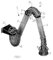
- the extraction arm illustrated in FIG. 1 and generally designated by numeral reference 1 is primarily intended for localized extraction of fumes, gas, oil mists and similar exhaust fumes.
- the main components of the extraction arm is a wall attachment 2 on which is mounted a motor-operated extraction fan, not shown.
- the arm 1 further comprises an inner arm 3 and an outer arm 4 made from smooth metal tubing and the arms 3, 4 are interconnected by means of a middle joint in accordance with the invention, generally designated by numeral reference 5.
- a flexible tube 6 extends between the inner arm 3 and the attachement 2 and at the free end of the outer arm 4 there is provided an extraction hood 7 and a ring-shaped operating handle 8 by means of which the extraction hood 7 and consequently the entire extraction arm assembly may be moved to the desired position.
- the middle joint 5 illustrated in closer detail in FIG. 2 is of the external type, i.e. it is positioned externally of the inner and outer arms 3 and 4 and it comprises two essentially identical halves 9 and 10 which in accordance with the embodiment illustrated are made from sheet metal.
- One of the joint halves 9 is connected to the outer end of the tubular inner arm 3 whereas the other joint half 10 is connected to the inner end of the tubular outer arm 4, more precisely with the aid of connecting pieces 11, 12 designed to be applied in a tight position about their respective arm end.
- a flexible piece of hose 13, see FIG. 1 extends between the two arm ends, whereby a continous fume extraction channel is formed, extending from the extraction hood 7 to the suction fan, not shown.
- Each joint half 9 and 10 is formed with two leg members 14, 15 and 16, 17, respectively, which project from the associated connection piece 11 and 12 so as to extend on either side of the piece of hose 13.
- the leg members are formed from flat sheet metal plates having through-holes formed therein and they have an arcuate configuration, tapering towards their free ends.
- each leg member 14, 15 and 16, 17, respectively is articulated to a corresponding leg member of the other joint half by means of bolt connections 18 and 19 to be described in closer detail in the following.
- these bolt connections 18, 19 consist of a bolt 20 which is non-rotationally attached to one of the leg members 14 and 17, respectively, of each joint half 9 and 10.
- the bolts 20 extend with some play through the opposite leg member 16 and 15, respectively, of the other joint half 10 and 9, respectively, and at their free ends they support a knob 21 which is screwed onto an associated bolt 20.
- the bolt connections which consist of bolts corresponding to bolts 20 and which are non-rotationally mounted in both leg members 14 and 15 or 16 and 17 of one of the joint halves 9 or 10. These bolts extend with some play through the two leg members 16, 17 or 14, 15 of the other joint half 10 or 9 and at their free ends these bolts support a knob corresponding to knob 21 which is threaded onto its associated bolt.
- the bolts 20 are carriage bolts which are non-rotationally mounted in square apertures, not shown, which are formed in the leg members.
- the knobs 21 on these bolts 20 preferably are in the shape of wheels formed with hand gripping surfaces.
- a driving member 22 and 23 is mounted intermediate the associated knob 21 and that face 24 of the adjacent leg member which is turned towards said driving members, in accordance with drawing figure 2 leg member 15 and leg member 16.
- Each knob 21 may be screwed towards or from its associated one of driving members 22 and 23 to adjust the movability of the middle joint 5 and each driving member 22 and 23 is anchored in the leg member - in accordance with figure 2 leg member 17 and 14 - to which the bolt 20 is non-rotationally attached.
- the driving members 22, 23 and consequently the knobs 21 thus will be imparted a movement identical to that of the associated bolt 20, whereby automatic unscrewing movements of the bolt connections 18 and 19 are prevented.
- the bolt connections as such thus will behave as if they were screwed into one single plate instead of to a movable middle joint.
- the driving members are in the shape of elongate plates which are formed at one of their ends with an aperture, not shown, for application of this plate end onto the associated bolt 20 intermediate the knob 21 and the leg member face 24 mentioned above, whereas the opposite plate end is bent inwards and is inserted in a slot 25 formed in the leg member, as explained in the aforegoing either leg member 17 or 14, in which the bolts 20 are non-rotationally mounted.
Landscapes
- Engineering & Computer Science (AREA)
- General Engineering & Computer Science (AREA)
- Mechanical Engineering (AREA)
- Manipulator (AREA)
- Extraction Or Liquid Replacement (AREA)
- Toys (AREA)
- Quick-Acting Or Multi-Walled Pipe Joints (AREA)
- Mutual Connection Of Rods And Tubes (AREA)
- Filtering Materials (AREA)
- Respiratory Apparatuses And Protective Means (AREA)
- Professional, Industrial, Or Sporting Protective Garments (AREA)
- Meat, Egg Or Seafood Products (AREA)
Claims (1)
- Äußeres, einstellbares mittleres Gelenk (5) für einen Abzugsarm (1), das zwei Hälften (9, 10) umfaßt, von denen eine (9) mit einem Ende eines inneren röhrenförmigen Arms (3) und die andere Hälfte (10) mit einem Ende eines äußeren röhrenförmigen Arms (4) über ihre jeweiligen Verbindungsstücke (11, 12) verbunden sind, sowie ein Stück flexiblen Schlauchs (13), der sich zwischen den Enden der röhrenförmigen Arme (3, 4) erstreckt und sie verbindet, wobei jede Gelenkhälfte (9, 10) zwei Schenkelglieder (14, 15 bzw. 16, 17) aufweist, die aus dem entsprechenden Verbindungsstück (11, 12) des Arms herausragen, so daß sie sich an beiden Seiten des Schlauchs (13) über dessen Länge hinweg erstrecken, und wobei die äußeren freien Enden der Schenkelglieder einer Gelenkhälfte (9 oder 10) an den entsprechenden gegenüberliegenden äußeren freien Enden der Schenkelglieder der anderen Gelenkhälfte (9 oder 10) mittels Schraubenverbindungen (18, 19) angelenkt sind, welche entweder eine Schraube (20) umfassen, die drehfest in einem (14 bzw. 17) der beiden Schenkelglieder jeder Gelenkhälfte (9, 10) befestigt ist und die sich mit Spiel durch das gegenüberliegende der beiden Schenkelglieder (16 bzw. 15) der anderen Hälfte (10 bzw. 9) des Gelenks erstreckt und an ihrem äußeren freien Ende ein Spannmittel (21) trägt, das auf die Schraube aufgeschraubt ist, oder Schrauben (20), die drehfest in beiden Schenkelgliedern (14, 15) einer der Gelenkhälften (9 oder 10) befestigt sind und sich mit Spiel durch die beiden Schenkelglieder (16, 17 oder 14, 15) der gegenüberliegenden Gelenkhälfte (10 oder 9) erstrecken, wobei jede Schraube an ihrem äußeren freien Ende ein Spannmittel (21) trägt, das auf die Schraube aufgeschraubt ist, wobei ein Antriebsglied (22 bzw. 23) an einer zwischen dem entsprechenden Spannmittel (21) und der Fläche (24) des benachbarten Schenkelglieds (15 bzw. 16) liegenden Stelle befestigt ist, die dem Antriebsglied (22 bzw. 23) zugewandt ist, wobei das Spannmittel (21) so angeordnet ist, daß es in eine Stellung gegen das Antriebsglied (21) geschraubt werden kann, um die Beweglichkeit des mittleren Gelenks (5) einzustellen, dadurch gekennzeichnet, daß beide Schenkelglieder (14, 15 und 16, 17) beider Gelenkhälften (9, 10) aus flachen Blechplatten bestehen, die eine sich zu den äußeren freien Enden der Schenkelglieder verjüngende, bogenförmige Konfiguration aufweisen, daß die Spannmittel in Form von Rädern (21) mit daran ausgebildeten Griffflächen vorliegen, und dadurch, daß die Antriebsglieder (22, 23) in denjenigen Schenkelgliedern (17 bzw. 14) verankert sind, in denen die Schrauben in Form von Schloßschrauben (20) in in dem einen Schenkelglied jeder Gelenkhälfte (9, 10) ausgebildeten viereckigen Öffnungen drehfest befestigt sind, wobei die Antriebsglieder in Form von länglichen Platten vorliegen, die an einem ihrer Enden mit einer Öffnung zum Anbringen an der zugehörigen Schloßschraube (20) an einer zwischen dem Rad (21) und der Fläche (24) liegenden Stelle versehen sind, und die an ihrem gegenüberliegenden Ende gebogen und mittels dieses Endes in ihrem jeweils zugeordneten der Schlitze (25) eingesetzt sind, die in den Schenkelgliedern (17 bzw. 14), in denen die Schloßschrauben (20) drehfest befestigt sind, ausgebildet sind, wodurch bei Schwenkbewegung des mittleren Gelenks (5) die Antriebsglieder (22, 23) und folglich die Räder (21) mit einer Bewegung beaufschlagt werden, die gleich der der zugehörigen Schloßschrauben (20) ist, und somit die den Schraubenverbindungen (18, 19) innewohnende Neigung, sich zu lösen, verhindert wird.
Priority Applications (1)
| Application Number | Priority Date | Filing Date | Title |
|---|---|---|---|
| AT90908100T ATE108100T1 (de) | 1989-04-13 | 1990-04-17 | Anordnung in rauchextraktionsröhren. |
Applications Claiming Priority (3)
| Application Number | Priority Date | Filing Date | Title |
|---|---|---|---|
| SE8901331 | 1989-04-13 | ||
| SE8901331A SE8901331D0 (sv) | 1989-04-13 | 1989-04-13 | Anordning vid utsugsarm |
| PCT/SE1990/000254 WO1990011845A1 (en) | 1989-04-13 | 1990-04-17 | An arrangement in fume extraction arms |
Publications (2)
| Publication Number | Publication Date |
|---|---|
| EP0467995A1 EP0467995A1 (de) | 1992-01-29 |
| EP0467995B1 true EP0467995B1 (de) | 1994-07-06 |
Family
ID=20375661
Family Applications (1)
| Application Number | Title | Priority Date | Filing Date |
|---|---|---|---|
| EP90908100A Expired - Lifetime EP0467995B1 (de) | 1989-04-13 | 1990-04-17 | Anordnung in rauchextraktionsröhren |
Country Status (8)
| Country | Link |
|---|---|
| EP (1) | EP0467995B1 (de) |
| AT (1) | ATE108100T1 (de) |
| AU (1) | AU5530790A (de) |
| DE (1) | DE69010493T2 (de) |
| DK (1) | DK0467995T3 (de) |
| ES (1) | ES2060169T3 (de) |
| SE (1) | SE8901331D0 (de) |
| WO (1) | WO1990011845A1 (de) |
Families Citing this family (4)
| Publication number | Priority date | Publication date | Assignee | Title |
|---|---|---|---|---|
| US5156697A (en) * | 1989-09-05 | 1992-10-20 | Board Of Regents, The University Of Texas System | Selective laser sintering of parts by compound formation of precursor powders |
| US5951725A (en) * | 1995-06-07 | 1999-09-14 | National Tool And Equipment, Inc. | System for removal of noxious fumes |
| EP2995387A3 (de) * | 2014-09-12 | 2016-06-29 | Filcar S.p.A. | Ein teleskopischer absaugarm |
| CN109719106A (zh) * | 2019-01-18 | 2019-05-07 | 江苏久华环保科技股份有限公司 | 一种钢铁厂室内粉尘吸收装置 |
Family Cites Families (2)
| Publication number | Priority date | Publication date | Assignee | Title |
|---|---|---|---|---|
| GB512175A (en) * | 1938-05-16 | 1939-08-30 | John Dugdill & Company Ltd | Improvements in or relating to joints for tubes |
| SE424409B (sv) * | 1975-12-04 | 1982-07-19 | Coral Sas | Anordning for lokaliserad utsugning av gaser, rokstoft och liknande |
-
1989
- 1989-04-13 SE SE8901331A patent/SE8901331D0/xx unknown
-
1990
- 1990-04-17 DK DK90908100.2T patent/DK0467995T3/da active
- 1990-04-17 AT AT90908100T patent/ATE108100T1/de not_active IP Right Cessation
- 1990-04-17 WO PCT/SE1990/000254 patent/WO1990011845A1/en not_active Ceased
- 1990-04-17 AU AU55307/90A patent/AU5530790A/en not_active Abandoned
- 1990-04-17 EP EP90908100A patent/EP0467995B1/de not_active Expired - Lifetime
- 1990-04-17 DE DE69010493T patent/DE69010493T2/de not_active Expired - Fee Related
- 1990-04-17 ES ES90908100T patent/ES2060169T3/es not_active Expired - Lifetime
Also Published As
| Publication number | Publication date |
|---|---|
| AU5530790A (en) | 1990-11-05 |
| ATE108100T1 (de) | 1994-07-15 |
| DE69010493T2 (de) | 1995-02-23 |
| DK0467995T3 (da) | 1994-11-07 |
| WO1990011845A1 (en) | 1990-10-18 |
| EP0467995A1 (de) | 1992-01-29 |
| SE8901331D0 (sv) | 1989-04-13 |
| DE69010493D1 (de) | 1994-08-11 |
| ES2060169T3 (es) | 1994-11-16 |
Similar Documents
| Publication | Publication Date | Title |
|---|---|---|
| US5211602A (en) | Arrangement in fume extraction arms | |
| US4860644A (en) | Articulatable fume exhauster trunk | |
| US2284222A (en) | Method of mounting fastening devices | |
| DE69423789D1 (de) | Stroemungsleiteinrichtung fuer den kompressorteil einer stroemungsmaschine | |
| CA2034332A1 (en) | Drive system for impeller shafts | |
| EP0467995B1 (de) | Anordnung in rauchextraktionsröhren | |
| ATE153427T1 (de) | Verbindung zwischen einer dreh- oder schwenkarmatur und einem drehantrieb | |
| US5527217A (en) | Adjustable device for exhaustion and/or supply of gas | |
| ES2165940T3 (es) | Tubo flexible sanitario, procedimiento y dispositivo de fabricacion. | |
| DE2634990C3 (de) | Kühlerbefestigung für Kraftfahrzeuge | |
| CA2051101C (en) | Arrangement in fume extraction arms | |
| US6082702A (en) | Tubing pinch valve and mounting bracket assembly | |
| ATE339644T1 (de) | Flanschglied mit einem ersten flanschende, das in einer radialrichtung mit einer konkaven endfläche ausgeführt ist, und einer flanschglieder umfassenden flanschverbindung | |
| BG101299A (en) | Housing for a support shoe in a trench falsework | |
| ATE21159T1 (de) | Klemme. | |
| DE8912783U1 (de) | Befestigungsclip | |
| USD325484S (en) | Console table | |
| IT1239056B (it) | Attrezzo manuale particolarmente per il montaggio e lo smontaggio di anelli elastici di arresto su alberi o fori | |
| ES2129243T3 (es) | Abrazadera para tubos. | |
| DE59306147D1 (de) | Leuchte | |
| JPS6127505Y2 (de) | ||
| IE880147L (en) | T-shaped branch pipe connector | |
| Enke | Room Temperature Creep of 60/40 Tin-Lead Solder Joints, Paper Presented at the ASME Winter Annual Meeting, Chicago, IL, Nov 27-Dec 2, 1988 | |
| ATA207592A (de) | Verbindung von schornstein-rohrteilen in axialer richtung mit hilfe einer wickelbaren manschette | |
| SE8205754D0 (sv) | Anordning vid en ledforbindning for vridrorelse |
Legal Events
| Date | Code | Title | Description |
|---|---|---|---|
| PUAI | Public reference made under article 153(3) epc to a published international application that has entered the european phase |
Free format text: ORIGINAL CODE: 0009012 |
|
| 17P | Request for examination filed |
Effective date: 19911008 |
|
| AK | Designated contracting states |
Kind code of ref document: A1 Designated state(s): AT BE CH DE DK ES FR GB IT LI LU NL SE |
|
| 17Q | First examination report despatched |
Effective date: 19930519 |
|
| GRAA | (expected) grant |
Free format text: ORIGINAL CODE: 0009210 |
|
| AK | Designated contracting states |
Kind code of ref document: B1 Designated state(s): AT BE CH DE DK ES FR GB IT LI LU NL SE |
|
| REF | Corresponds to: |
Ref document number: 108100 Country of ref document: AT Date of ref document: 19940715 Kind code of ref document: T |
|
| REF | Corresponds to: |
Ref document number: 69010493 Country of ref document: DE Date of ref document: 19940811 |
|
| ITF | It: translation for a ep patent filed | ||
| ET | Fr: translation filed | ||
| REG | Reference to a national code |
Ref country code: DK Ref legal event code: T3 |
|
| REG | Reference to a national code |
Ref country code: ES Ref legal event code: FG2A Ref document number: 2060169 Country of ref document: ES Kind code of ref document: T3 |
|
| EAL | Se: european patent in force in sweden |
Ref document number: 90908100.2 |
|
| PG25 | Lapsed in a contracting state [announced via postgrant information from national office to epo] |
Ref country code: LU Free format text: LAPSE BECAUSE OF NON-PAYMENT OF DUE FEES Effective date: 19950430 |
|
| PLBE | No opposition filed within time limit |
Free format text: ORIGINAL CODE: 0009261 |
|
| STAA | Information on the status of an ep patent application or granted ep patent |
Free format text: STATUS: NO OPPOSITION FILED WITHIN TIME LIMIT |
|
| 26N | No opposition filed | ||
| PGFP | Annual fee paid to national office [announced via postgrant information from national office to epo] |
Ref country code: AT Payment date: 19980225 Year of fee payment: 9 |
|
| PGFP | Annual fee paid to national office [announced via postgrant information from national office to epo] |
Ref country code: BE Payment date: 19980304 Year of fee payment: 9 |
|
| PGFP | Annual fee paid to national office [announced via postgrant information from national office to epo] |
Ref country code: ES Payment date: 19980408 Year of fee payment: 9 |
|
| PGFP | Annual fee paid to national office [announced via postgrant information from national office to epo] |
Ref country code: CH Payment date: 19980731 Year of fee payment: 9 |
|
| PG25 | Lapsed in a contracting state [announced via postgrant information from national office to epo] |
Ref country code: AT Free format text: LAPSE BECAUSE OF NON-PAYMENT OF DUE FEES Effective date: 19990417 |
|
| PG25 | Lapsed in a contracting state [announced via postgrant information from national office to epo] |
Ref country code: ES Free format text: LAPSE BECAUSE OF NON-PAYMENT OF DUE FEES Effective date: 19990419 |
|
| PG25 | Lapsed in a contracting state [announced via postgrant information from national office to epo] |
Ref country code: BE Free format text: LAPSE BECAUSE OF NON-PAYMENT OF DUE FEES Effective date: 19990430 Ref country code: CH Free format text: LAPSE BECAUSE OF NON-PAYMENT OF DUE FEES Effective date: 19990430 Ref country code: LI Free format text: LAPSE BECAUSE OF NON-PAYMENT OF DUE FEES Effective date: 19990430 |
|
| BERE | Be: lapsed |
Owner name: J H PLYMOTH A.B. Effective date: 19990430 |
|
| REG | Reference to a national code |
Ref country code: CH Ref legal event code: PL |
|
| REG | Reference to a national code |
Ref country code: ES Ref legal event code: FD2A Effective date: 20010503 |
|
| REG | Reference to a national code |
Ref country code: GB Ref legal event code: IF02 |
|
| PGFP | Annual fee paid to national office [announced via postgrant information from national office to epo] |
Ref country code: SE Payment date: 20050615 Year of fee payment: 16 |
|
| PGFP | Annual fee paid to national office [announced via postgrant information from national office to epo] |
Ref country code: DE Payment date: 20050623 Year of fee payment: 16 Ref country code: NL Payment date: 20050623 Year of fee payment: 16 |
|
| PGFP | Annual fee paid to national office [announced via postgrant information from national office to epo] |
Ref country code: GB Payment date: 20050926 Year of fee payment: 16 |
|
| PGFP | Annual fee paid to national office [announced via postgrant information from national office to epo] |
Ref country code: DK Payment date: 20051026 Year of fee payment: 16 |
|
| PGFP | Annual fee paid to national office [announced via postgrant information from national office to epo] |
Ref country code: FR Payment date: 20051028 Year of fee payment: 16 |
|
| PG25 | Lapsed in a contracting state [announced via postgrant information from national office to epo] |
Ref country code: GB Free format text: LAPSE BECAUSE OF NON-PAYMENT OF DUE FEES Effective date: 20060417 |
|
| PG25 | Lapsed in a contracting state [announced via postgrant information from national office to epo] |
Ref country code: SE Free format text: LAPSE BECAUSE OF NON-PAYMENT OF DUE FEES Effective date: 20060418 |
|
| PGFP | Annual fee paid to national office [announced via postgrant information from national office to epo] |
Ref country code: IT Payment date: 20060430 Year of fee payment: 17 |
|
| PG25 | Lapsed in a contracting state [announced via postgrant information from national office to epo] |
Ref country code: DK Free format text: LAPSE BECAUSE OF NON-PAYMENT OF DUE FEES Effective date: 20060501 |
|
| PG25 | Lapsed in a contracting state [announced via postgrant information from national office to epo] |
Ref country code: NL Free format text: LAPSE BECAUSE OF NON-PAYMENT OF DUE FEES Effective date: 20061101 Ref country code: DE Free format text: LAPSE BECAUSE OF NON-PAYMENT OF DUE FEES Effective date: 20061101 |
|
| REG | Reference to a national code |
Ref country code: DK Ref legal event code: EBP |
|
| EUG | Se: european patent has lapsed | ||
| GBPC | Gb: european patent ceased through non-payment of renewal fee |
Effective date: 20060417 |
|
| NLV4 | Nl: lapsed or anulled due to non-payment of the annual fee |
Effective date: 20061101 |
|
| REG | Reference to a national code |
Ref country code: FR Ref legal event code: ST Effective date: 20061230 |
|
| PG25 | Lapsed in a contracting state [announced via postgrant information from national office to epo] |
Ref country code: FR Free format text: LAPSE BECAUSE OF NON-PAYMENT OF DUE FEES Effective date: 20060502 |
|
| PG25 | Lapsed in a contracting state [announced via postgrant information from national office to epo] |
Ref country code: IT Free format text: LAPSE BECAUSE OF NON-PAYMENT OF DUE FEES Effective date: 20070417 |