EP0467090B1 - Laser pulse transmitter for a weapon - Google Patents
Laser pulse transmitter for a weapon Download PDFInfo
- Publication number
- EP0467090B1 EP0467090B1 EP91110128A EP91110128A EP0467090B1 EP 0467090 B1 EP0467090 B1 EP 0467090B1 EP 91110128 A EP91110128 A EP 91110128A EP 91110128 A EP91110128 A EP 91110128A EP 0467090 B1 EP0467090 B1 EP 0467090B1
- Authority
- EP
- European Patent Office
- Prior art keywords
- laser pulse
- pulse transmitter
- laser
- weapon
- transmitter according
- Prior art date
- Legal status (The legal status is an assumption and is not a legal conclusion. Google has not performed a legal analysis and makes no representation as to the accuracy of the status listed.)
- Expired - Lifetime
Links
- 229910000831 Steel Inorganic materials 0.000 claims description 7
- 239000010959 steel Substances 0.000 claims description 7
- 239000003990 capacitor Substances 0.000 claims description 5
- 229910052751 metal Inorganic materials 0.000 claims description 5
- 239000002184 metal Substances 0.000 claims description 5
- 229910000760 Hardened steel Inorganic materials 0.000 claims description 2
- 238000005516 engineering process Methods 0.000 claims description 2
- 239000000919 ceramic Substances 0.000 claims 1
- 239000004429 Calibre Substances 0.000 abstract 1
- 238000010304 firing Methods 0.000 description 7
- 238000010586 diagram Methods 0.000 description 2
- 229910000679 solder Inorganic materials 0.000 description 2
- WHXSMMKQMYFTQS-UHFFFAOYSA-N Lithium Chemical compound [Li] WHXSMMKQMYFTQS-UHFFFAOYSA-N 0.000 description 1
- 238000005452 bending Methods 0.000 description 1
- 239000004020 conductor Substances 0.000 description 1
- 238000010276 construction Methods 0.000 description 1
- 229910052744 lithium Inorganic materials 0.000 description 1
- 238000012986 modification Methods 0.000 description 1
- 230000004048 modification Effects 0.000 description 1
- 238000005476 soldering Methods 0.000 description 1
- 230000001960 triggered effect Effects 0.000 description 1
Images

Classifications
-
- F—MECHANICAL ENGINEERING; LIGHTING; HEATING; WEAPONS; BLASTING
- F41—WEAPONS
- F41A—FUNCTIONAL FEATURES OR DETAILS COMMON TO BOTH SMALLARMS AND ORDNANCE, e.g. CANNONS; MOUNTINGS FOR SMALLARMS OR ORDNANCE
- F41A33/00—Adaptations for training; Gun simulators
- F41A33/02—Light- or radiation-emitting guns ; Light- or radiation-sensitive guns; Cartridges carrying light emitting sources, e.g. laser
Definitions
- the invention relates to a laser pulse transmitter for a weapon according to the preamble of claim 1.
- a laser pulse transmitter of the type mentioned is known from US Pat. No. 3,938,262.
- a piezoelectric converter serves as a switch for triggering the laser pulse transmitter and as a current source. This results in the disadvantages that the converter must be relatively large for an adequate power supply and, on the other hand, considerable impact is required.
- the large design limits the laser pulse transmitter to weapons of large caliber. The high impact can also damage the pulse transmitter and / or the firing pin and thus the weapon.
- the object of the invention is to design a laser pulse transmitter so that the disadvantages mentioned are avoided.
- the piezoelectric transducer Since the piezoelectric transducer is only used as a switch, very small current surges are sufficient to trigger the circuit and thus to send out the laser signal.
- the converter can therefore be kept very small and the impact force of the firing pin reduced or damped accordingly. This in turn leads to protection of the laser pulse transmitter and the weapon. Due to the small design, it can also be used in small-caliber weapons.
- the circuit and its arrangement can be designed in various forms and arranged in a sleeve. A very useful solution is described in claim 4, since then no additional mechanical holding devices are required, but the printed circuit board is held in the cylinder of the sleeve. If necessary, batteries can also be arranged on both sides of the printed circuit board.
- the laser collimator can be arranged according to claim 9 at the front end of the insert, this being possible only for weapons of a certain caliber.
- the training according to claim 10 is particularly suitable.
- the laser pulse transmitter insert can be designed for a wide variety of weapons, i.e. have the shape of the required cartridge.
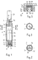
- the laser pulse transmitter shown in FIGS. 1 to 3 has an insert housing in the form of the cartridge of a weapon, which contains a sleeve 2 with a front holder 4 and a rear holder 6.
- the rear holder 6 is formed in one piece with the sleeve 2 and serves to receive a switch 8 of the laser pulse transmitter.
- This contains a piezoelectric transducer, preferably a piezoceramic 10 and is mounted in a recess 12 in the holder 6.
- the piezoceramic 10 is arranged between two metal plates 14 and 16, each having a conductor 18 and 20 of the piezoceramic.
- the outer metal plate 16 is preferably made of hardened steel in order to prevent damage to the piezoceramic 10 by the firing pin of a weapon.
- An outer plate 22 serves to secure the arrangement in the rear holder 6 of the sleeve.
- the front holder 4 is removably arranged on the sleeve 2 and secured by means of a stud 24. At the front end of the holder 4, this carries a laser collimator in a recess 26.
- the lines 30 used to connect the laser collimator 28 run through the holder 4.
- a chamber 32 is formed, in which a printed circuit board 34 is arranged, the width of which corresponds to the inner diameter of the sleeve 2 and the length of which corresponds to the length of the chamber 32.
- a power source 36 consisting of two batteries is arranged on one side of the printed circuit board 34 and a driver circuit 38 for the laser collimator 28 on the opposite side.
- the driver circuit is designed such that it generates a shot pulse of 10 microseconds, for example. With the laser pulse transmitter shown, more than a million shots can be fired.
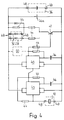
- a corresponding modulator 50 is indicated by dashed lines in the circuit according to FIG. 4.
- FIG. 5 shows a further advantageous switch 52 for the laser pulse transmitter.
- the switch contains a switch housing 54 made of plastic, which can be inserted into a recess of the holder 6 of the sleeve 2 and into which a pot-shaped cover 56 made of plastic is inserted, which has a central opening 58 for receiving a steel ball 60, onto which the firing pin of the weapon is fired the same strikes.
- the steel ball 60 is supported on the inside on a preferably prestressed elastic ring 62, which rests on a steel plate 64, under which a piezoceramic 66 is arranged, which is supported on the inside on a further plate 68.
- FIG. 6 shows a further laser pulse transmitter which contains the switch 52 shown in FIG. 5 on one side of the housing.
- the housing 78 in turn forms a chamber 80 in which a printed circuit board 82 with a driver circuit and a battery analogous to the example in FIG. 1 are arranged after the switch 52.
- the printed circuit board 82 occupies only a portion of the chamber 80, a laser collimator 84 connecting to the printed circuit board 82 against the front end of the housing.
- the front end of the housing 78 is formed by a centering insert 86 which can be inserted into the barrel of a weapon and is used to center the laser pulse transmitter.
- the centering insert 86 contains a pinhole 88 at the front end to align the laser beam with the axis of the weapon.
Landscapes
- Physics & Mathematics (AREA)
- Optics & Photonics (AREA)
- Engineering & Computer Science (AREA)
- General Engineering & Computer Science (AREA)
- Aiming, Guidance, Guns With A Light Source, Armor, Camouflage, And Targets (AREA)
- Optical Radar Systems And Details Thereof (AREA)
- Toys (AREA)
- Semiconductor Lasers (AREA)
Abstract
Description
Die Erfindung betrifft einen Laser-Impulssender für eine Waffe gemäss Oberbegriff des Anspruches 1.The invention relates to a laser pulse transmitter for a weapon according to the preamble of
Aus der US-PS 3 938 262 ist ein Laser-Impulssender der eingangs genannten Art bekannt. Als Schalter zum Auslösen des Laser-Impulssenders sowie als Stromquelle dient ein piezoelektrischer Wandler. Daraus ergeben sich die Nachteile, dass für eine ausreichende Stromversorgung der Wandler relativ gross sein muss und andererseits eine erhebliche Schlagkraft erforderlich ist. Die grosse Bauweise beschränkt den Laser-Impulssender auf Waffen grossen Kalibers. Die hohe Schlagkraft kann überdies zu einer Beschädigung des Impulssenders und/oder des Schlagbolzens und damit der Waffe führen.A laser pulse transmitter of the type mentioned is known from US Pat. No. 3,938,262. A piezoelectric converter serves as a switch for triggering the laser pulse transmitter and as a current source. This results in the disadvantages that the converter must be relatively large for an adequate power supply and, on the other hand, considerable impact is required. The large design limits the laser pulse transmitter to weapons of large caliber. The high impact can also damage the pulse transmitter and / or the firing pin and thus the weapon.
Aufgabe der Erfindung ist es, einen Laser-Impulssender so auszubilden, dass die erwähnten Nachteile vermieden werden.The object of the invention is to design a laser pulse transmitter so that the disadvantages mentioned are avoided.
Die gestellte Aufgabe wird durch die Merkmale des Anspruches 1 gelöst.The object is achieved by the features of
Da der piezoelektrische Wandler nur als Schalter benutzt wird, genügen sehr kleine Stromstösse zur Auslösung des Schaltkreises und damit zum Aussenden des Laser-Signals. Der Wandler kann deshalb sehr klein gehalten und die Schlagkraft des Schlagbolzens reduziert bzw. entsprechend gedämpft werden. Dies führt wiederum zu einer Schonung des Laser-Impulssenders wie der Waffe. Durch die kleine Bauweise ist auch ein Einsatz in kleinkalibrigen Waffen möglich.Since the piezoelectric transducer is only used as a switch, very small current surges are sufficient to trigger the circuit and thus to send out the laser signal. The converter can therefore be kept very small and the impact force of the firing pin reduced or damped accordingly. This in turn leads to protection of the laser pulse transmitter and the weapon. Due to the small design, it can also be used in small-caliber weapons.
Vorteilhafte Ausgestaltungen des Laser-Impulssenders sind in den Ansprüchen 2 bis 10 beschrieben.Advantageous embodiments of the laser pulse transmitter are described in
Für die Anordnung des piezoelektrischen Wandlers gibt es verschiedene Ausgestaltungsmöglichkeiten. Besonders vorteilhaft ist jedoch eine Ausbildung nach Anspruch 2 und die Weiterbildung nach Anspruch 3. Letztere verhindert besonders wirksam eine Beschädigung des piezoelektrischen Wandlers und eine zu hohe Spannung beim Auslösen durch den Schlagbolzen einer Waffe.There are various design options for the arrangement of the piezoelectric transducer. However, a design according to
Die Schaltung und deren Anordnung kann in verschiedener Form ausgebildet und in einer Hülse angeordnet sein. Eine sehr zweckmässige Lösung beschreibt Anspruch 4, da dann keine zusätzlichen mechanischen Haltevorrichtungen erforderlich sind, sondern die Printplatte im Zylinder der Hülse gehaltert ist. Gegebenenfalls können Batterien auch auf beiden Seiten der Printplatte angeordnet sein.The circuit and its arrangement can be designed in various forms and arranged in a sleeve. A very useful solution is described in
Um die Treiberschaltung möglichst klein zu halten, ist es zweckmässig, sie nach Anspruch 5 auszugestalten. Eine noch kleinere Bauweise ermöglicht die Ausbildung nach Anspruch 6. Eine hohe Schussleistung bei geringstem Stromverbrauch ermöglicht eine Ausgestaltung nach Anspruch 7. Besonders vorteilhaft ist jedoch auch eine Weiterbildung nach Anspruch 8, die es einerseits ermöglicht, insbesondere auf lange Distanzen Fremdlicht auszuschalten und andererseits differenziertere Empfangsmöglichkeiten an der Zielscheibe gestattet.In order to keep the driver circuit as small as possible, it is expedient to design it according to claim 5. An even smaller construction enables the design according to
Der Laser-Kollimator kann gemäss Anspruch 9 am vorderen Ende des Einsatzes angeordnet sein, wobei dies nur für Waffen eines bestimmten Kalibers möglich ist. Für Kleinkalibrigere Waffen ist die Ausbildung nach Anspruch 10 besonders geeignet.The laser collimator can be arranged according to claim 9 at the front end of the insert, this being possible only for weapons of a certain caliber. For small-caliber weapons, the training according to
Der Laser-Impulssender-Einsatz kann für die verschiedensten Waffen ausgestaltet sein, d.h. die Form der jeweils erforderlichen Patrone aufweisen.The laser pulse transmitter insert can be designed for a wide variety of weapons, i.e. have the shape of the required cartridge.
Vorteilhafte Ausführungsbeispiele des Gegenstandes der Erfindung werden nachfolgend anhand der Zeichnungen näher beschrieben, dabei zeigen:
Figur 1- einen Laser-Impulssender im Längsschnitt;
Figur 2- den Laser-Impulssender im Schnitt II-II der
Figur 1; - Figur 3
- den Laser-Impulssender im Schnitt III-III der
Figur 1; Figur 4- das Schaltschema des Laser-Impulssenders der
Figur 1; - Figur 5
- einen weiteren Schalter für den Laser-Impulssender im Längsschnitt und in grösserem Massstab;
Figur 6- einen weiteren Laser-Impulssender im Längsschnitt.
- Figure 1
- a laser pulse transmitter in longitudinal section;
- Figure 2
- the laser pulse transmitter in section II-II of Figure 1;
- Figure 3
- the laser pulse transmitter in section III-III of Figure 1;
- Figure 4
- the circuit diagram of the laser pulse transmitter of Figure 1;
- Figure 5
- another switch for the laser pulse transmitter in longitudinal section and on a larger scale;
- Figure 6
- another laser pulse transmitter in longitudinal section.
Der in den Figuren 1 bis 3 dargestellte Laser-Impulssender weist ein Einsatz-Gehäuse in der Form der Patrone einer Waffe auf, das eine Hülse 2 mit einem vorderen Halter 4 und einem hinteren Halter 6 enthält. Der hintere Halter 6 ist mit der Hülse 2 einteilig ausgebildet und dient zur Aufnahme eines Schalters 8 des Laser-Impulssenders. Dieser enthält einen piezoelektrischen Wandler, vorzugsweise eine Piezokeramik 10 und ist in einer Ausnehmung 12 des Halters 6 gelagert. Hierzu ist die Piezokeramik 10 zwischen zwei Metallplatten 14 und 16 angeordnet, die jeweils einen Leiter 18 und 20 der Piezokeramik aufweisen. Die äussere Metallplatte 16 besteht vorzugsweise aus gehärtetem Stahl, um eine Beschädigung der Piezokeramik 10 durch den Schlagbolzen einer Waffe zu verhindern. Eine äussere Platte 22 dient zur Absicherung der Anordnung im hinteren Halter 6 der Hülse. Der vordere Halter 4 ist abnehmbar an der Hülse 2 angeordnet und mittels einer Stiftschraube 24 gesichert. Am vorderen Ende des Halters 4 trägt dieser in einer Ausnehmung 26 einen Laser-Kollimator. Die zum Anschluss des Laser-Kollimators 28 dienenden Leitungen 30 verlaufen durch den Halter 4.The laser pulse transmitter shown in FIGS. 1 to 3 has an insert housing in the form of the cartridge of a weapon, which contains a
Zwischen den Haltern 4 und 6 ist eine Kammer 32 gebildet, in der eine Printplatte 34 angeordnet ist, deren Breite dem Innendurchmesser der Hülse 2 und deren Länge der Länge der Kammer 32 entspricht. Auf der einen Seite der Printplatte 34 ist eine Stromquelle 36 aus zwei Batterien angeordnet und auf der gegenüberliegenden Seite eine Treiberschaltung 38 für den Laser-Kollimator 28.Between the
Die Figur 4 zeigt das Schaltbild des Laser-Impulssenders, wobei mit Ausnahme der Bauteile: Piezokeramik 10, Laser-Kollimator 28 (Typ CQL75A/D 2,5 mW Philips), sowie die Stromquelle 36 (beispielsweise 1 oder 2 Lithium-Batterien BR 211, 3V, 5,4 mAh), alle übrigen Bauteile als SMD-Komponenten auf der Printplatte 34 enthalten sind. Dies betrifft insbesondere die IC-Komponenten 40, Transistoren 42, Widerstände 44 und Kondensatoren 46. Der Kondensator 46a liefert die zum Zünden des Laser-Kollimators 28 erforderliche höhere Stromstärke. Die der Printplatte zugeordneten Bauteile sind über Steckverbindungen 48 angeschlossen.FIG. 4 shows the circuit diagram of the laser pulse transmitter, with the exception of the components: piezoceramic 10, laser collimator 28 (type CQL75A / D 2.5 mW Philips), and the power source 36 (for example 1 or 2 lithium batteries BR 211 , 3V, 5.4 mAh), all other components are contained as SMD components on the printed
Die Treiberschaltung ist so ausgelegt, dass sie beispielsweise einen Schussimpuls von 10 Mikrosekunden erzeugt. Mit dem gezeigten Laser-Impulssender können mehr als eine Million Schuss abgegeben werden.The driver circuit is designed such that it generates a shot pulse of 10 microseconds, for example. With the laser pulse transmitter shown, more than a million shots can be fired.
Im Gegensatz zum gezeigten Ausführungsbeispiel ist es auch noch möglich, den Laser-Impulssender so auszugestalten, dass der Schussimpuls moduliert ist, um insbesondere beim Schiessen auf grössere Distanz Fremdlichteinflüsse auszuschalten und/oder eine Zielscheibenvorrichtung zu betreiben, die modulierte Schussimpulse erfordert. Ein entsprechender Modulator 50 ist gestrichelt in der Schaltung gemäss Figur 4 angedeutet.In contrast to the exemplary embodiment shown, it is also possible to design the laser pulse transmitter in such a way that the shot pulse is modulated in order to switch off extraneous light influences, in particular when shooting at a greater distance, and / or to operate a target device which requires modulated shot pulses. A corresponding
In Abwandlung des gezeigten bzw. beschriebenen Ausführungsbeispieles ist es auch möglich, die als Stromquelle dienenden Batterien beidseits der Printplatte anzuordnen. Eine weitere Miniaturisierung der Treiberschaltung ist bei deren Ausbildung in Hybridtechnik möglich.In a modification of the exemplary embodiment shown or described, it is also possible to arrange the batteries serving as current sources on both sides of the printed circuit board. A further miniaturization of the driver circuit is possible when it is trained in hybrid technology.
Die Figur 5 zeigt einen weiteren vorteilhaften Schalter 52 für den Laser-Impulssender. Der Schalter enthält ein in eine Ausnehmung des Halters 6 der Hülse 2 einsetzbares Schaltergehäuse 54 aus Kunststoff, in das ein topfförmiger Deckel 56 aus Kunststoff eingesetzt ist, welcher eine zentrale Oeffnung 58 zur Aufnahme einer Stahlkugel 60 aufweist, auf die der Schlagbolzen der Waffe beim Abfeuern derselben auftrifft. Die Stahlkugel 60 stützt sich nach innen auf einem vorzugsweise vorgespannten elastischen Ring 62 ab, der auf einer Stahlplatte 64 aufliegt, unter der eine Piezokeramik 66 angeordnet ist, die sich nach innen auf einer weiteren Platte 68 abstützt. Beidseits der Piezokeramik 66 sind Kontaktscheiben 70,72 mit Lötfahnen 74,76 vorhanden, die nach dem Zurückbiegen die Verbindung zum Schaltkreis des Laser-Impulssenders herstellen. Durch diese Ausbildung des Schalters wird die Schlagenergie des Schlagbolzens so stark abgebremst, dass einerseits Beschädigungen des Schalter, insbesondere der Piezokeramik, sowie des Schlagbolzens und andererseits eine zu hohe Spannung der Piezokeramik verhindert werden.FIG. 5 shows a further
Die Figur 6 zeigt einen weiteren Laser-Impulssender, der auf einer Seite des Gehäuses den in Figur 5 gezeigten Schalter 52 enthält. Das Gehäuse 78 bildet wiederum eine Kammer 80, in der anschliessend an den Schalter 52 eine Printplatte 82 mit Treiberschaltung und Batterie analog dem Beispiel der Figur 1 angeordnet sind. Die Printplatte 82 nimmt jedoch nur einen Abschnitt der Kammer 80 ein, wobei sich gegen das vordere Ende des Gehäuses ein Laser-Kollimator 84 an die Printplatte 82 anschliesst. Den vorderen Abschluss des Gehäuses 78 bildet ein Zentriereinsatz 86, der in den Lauf einer Waffe einsetzbar ist und zur Zentrierung des Laser-Impulssenders dient. Der Zentriereinsatz 86 enthält am vorderen Ende eine Lochblende 88, um den Laserstrahl zur Achse der Waffe auszurichten.FIG. 6 shows a further laser pulse transmitter which contains the
- 11
- Einsatz-GehäuseInsert housing
- 22nd
- HülseSleeve
- 44th
- Halter, vorneBracket, front
- 66
- Halter, hintenBracket, rear
- 88th
- Schaltercounter
- 1010th
- PiezokeramikPiezoceramic
- 1212th
- AusnehmungRecess
- 1414
- MetallplatteMetal plate
- 1616
- MetallplatteMetal plate
- 1818th
- Leiterladder
- 2020th
- Leiterladder
- 2222
- Platteplate
- 2424th
- StiftschraubeStud screw
- 2626
- AusnehmungRecess
- 2828
- Laser-KollimatorLaser collimator
- 3030th
- Leitungmanagement
- 3232
- Kammerchamber
- 3434
- PrintplattePrinted circuit board
- 3636
- StromquellePower source
- 3838
- TreiberschaltungDriver circuit
- 4040
- IC-KomponenteIC component
- 4242
- Transistortransistor
- 4444
- Widerstandresistance
- 4646
- Kondensatorcapacitor
- 46a46a
- Kondensatorcapacitor
- 4848
- SteckverbindungConnector
- 5050
- Modulatormodulator
- 5252
- Schaltercounter
- 5454
- SchaltergehäuseSwitch housing
- 5656
- Deckelcover
- 5858
- OeffnungOpening
- 6060
- StahlkugelSteel ball
- 6262
- elastischer Ringelastic ring
- 6464
- Stahlplattesteel plate
- 6666
- PiezokeramikPiezoceramic
- 6868
- Platteplate
- 7070
- KontaktscheibeContact washer
- 7272
- KontaktscheibeContact washer
- 7474
- LötfahneSolder tail
- 7676
- LötfahneSolder tail
- 7878
- Gehäusecasing
- 8080
- Kammerchamber
- 8282
- PrintplattePrinted circuit board
- 8484
- Laser-KollimatorLaser collimator
- 8686
- ZentriereinsatzCentering insert
- 8888
- LochblendePinhole
Claims (10)
- Laser pulse transmitter for a weapon, with an inset insertable in a weapon, with a laser collimator (28,84) and with a piezoelectric transducer (10,66) that can be actuated by a striking pin, the inset having essentially the shape and size of a cartridge suitable for a weapon to the effect that the inset can be inserted in the breech of a weapon in place of the cartridge and that it contains all components for its function, characterized in that the piezoelectric transducer (10,66) is constructed merely as a switch (8,52) and that a battery (36) is present for supplying the current.
- Laser pulse transmitter according to claim 1, characterized in that the piezoelectric transducer (10,66) is arranged between two metal plates (14,16,64,68) serving as connections, the outer of which is made preferably of hardened steel.
- Laser pulse transmitter according to claim 1 or 2, characterized in that the piezoelectric transducer comprises a steel ball (60) facing the outside, the steel ball being supported to the inside on an elastic, preferably prestressed ring (62) which is arranged over a cover (64) of the piezoelectric ceramic (66).
- Laser pulse transmitter according to any one of claims 1 to 3, characterized in that the transmitter comprises a printed circuit board (34) extending in the longitudinal direction of a case (2) and having a width corresponding to the inside diameter of the case (2), the battery (36) preferably being arranged on the one side of the printed circuit board (34) and a driver circuit (38) preferably on the opposite side.
- Laser pulse transmitter according to claim 2, characterized in that the driver circuit (38) is constructed of SMD components.
- Laser pulse transmitter according to claim 1, characterized in that the driver circuit (38) is constructed of hybrid technology.
- Laser pulse transmitter according to claim 4, characterized in that the driver circuit (38) is equipped with a capacitor (46a) for igniting the laser collimator (28).
- Laser pulse transmitter according to claim 4, characterized in that the driver circuit (38) is equipped with a modulator (50) for the laser collimator (28).
- Laser pulse transmitter according to any one of claims 1 to 8, characterized in that the transmitter is equipped with a laser collimator (28) arranged at the front end of the element which projects into the barrel of the weapon.
- Laser pulse transmitter according to any one of claims 1 to 8, characterized in that the case of the inset (1) comprises a sleeve (2) closed off at each end by a support (4,6), the battery and a printed circuit board (82) with the driver circuit and the laser collimator (84) being arranged in the chamber (80) formed between the supports (4,6) and the front end of the sleeve containing a centering element (86) projecting into the barrel of a weapon, an orifice (88) for the laser beam being arranged at the front end of said centering element.
Applications Claiming Priority (2)
| Application Number | Priority Date | Filing Date | Title |
|---|---|---|---|
| CH232090 | 1990-07-11 | ||
| CH2320/90 | 1991-01-28 |
Publications (2)
| Publication Number | Publication Date |
|---|---|
| EP0467090A1 EP0467090A1 (en) | 1992-01-22 |
| EP0467090B1 true EP0467090B1 (en) | 1994-12-28 |
Family
ID=4231056
Family Applications (1)
| Application Number | Title | Priority Date | Filing Date |
|---|---|---|---|
| EP91110128A Expired - Lifetime EP0467090B1 (en) | 1990-07-11 | 1991-06-20 | Laser pulse transmitter for a weapon |
Country Status (3)
| Country | Link |
|---|---|
| EP (1) | EP0467090B1 (en) |
| AT (1) | ATE116426T1 (en) |
| DE (1) | DE59104027D1 (en) |
Families Citing this family (12)
| Publication number | Priority date | Publication date | Assignee | Title |
|---|---|---|---|---|
| NO178651C (en) * | 1994-01-11 | 1996-05-08 | Trojan Aviat As | Optical cartridge |
| FR2718841A1 (en) * | 1994-04-15 | 1995-10-20 | Mengus Marc | Target simulator for firearm sighting training |
| WO2001051875A2 (en) | 2000-01-13 | 2001-07-19 | Beamhit, Llc | Firearm laser training system and method employing modified blank cartridges for simulating operation of a firearm |
| WO2001055664A2 (en) * | 2000-01-13 | 2001-08-02 | Beamhit, Llc | Laser transmitter assembly configured for placement within a firing chamber and method of simulating firearm operation |
| AU2001268330A1 (en) | 2000-06-09 | 2001-12-17 | Beamhit, L.L.C. | Firearm laser training system and method facilitating firearm training with various targets and visual feedback of simulated projectile impact locations |
| EP1402224A2 (en) | 2001-06-08 | 2004-03-31 | Beamhit, LLC | Firearm laser training system and method facilitating firearm training for extended range targets with feedback of firearm control |
| EP1738131A2 (en) | 2004-03-18 | 2007-01-03 | Rovatec Ltd. | Firearm training aid |
| US8734156B2 (en) | 2010-01-19 | 2014-05-27 | Oren Louis Uhr | Dry fire training device |
| US8568143B2 (en) | 2010-05-13 | 2013-10-29 | Oren Louis Uhr | Training barrel |
| US8584587B2 (en) | 2010-01-19 | 2013-11-19 | Oren Louis Uhr | Drill cartridges, adaptors, and methods for multi-caliber drill cartridge training |
| KR101558971B1 (en) | 2014-03-12 | 2015-10-13 | 충북대학교 산학협력단 | Pulse generator for producing high-intensity circularly polarized laser pulses |
| CN111595211B (en) * | 2020-06-24 | 2024-06-04 | 湖南天合终极防务科技实业有限公司 | High penetration bullet |
Family Cites Families (6)
| Publication number | Priority date | Publication date | Assignee | Title |
|---|---|---|---|---|
| DE2254141A1 (en) * | 1972-11-04 | 1974-05-16 | Und Bei Rhein Moritz Pr Hessen | PRACTICE CARTRIDGE FOR FIRE WEAPONS |
| US3938262A (en) * | 1974-10-17 | 1976-02-17 | Hughes Aircraft Company | Laser weapon simulator |
| US4481561A (en) * | 1983-02-01 | 1984-11-06 | Site-Lite, Inc. | Gun bore sighting flashlight activated upon breech closure |
| US4678437A (en) * | 1985-09-27 | 1987-07-07 | Technology Network International, Inc. | Cartridge and target device for markmanship training |
| DE3537323A1 (en) * | 1985-10-19 | 1987-04-23 | Sis Ges Fuer Schiesstrainings | Optical aiming apparatus which is intended for installation in the barrel of a weapon |
| US4983123A (en) * | 1989-11-06 | 1991-01-08 | Phase Dynamics, Inc. | Marksmanship training apparatus |
-
1991
- 1991-06-20 DE DE59104027T patent/DE59104027D1/en not_active Expired - Fee Related
- 1991-06-20 AT AT91110128T patent/ATE116426T1/en not_active IP Right Cessation
- 1991-06-20 EP EP91110128A patent/EP0467090B1/en not_active Expired - Lifetime
Also Published As
| Publication number | Publication date |
|---|---|
| ATE116426T1 (en) | 1995-01-15 |
| EP0467090A1 (en) | 1992-01-22 |
| DE59104027D1 (en) | 1995-02-09 |
Similar Documents
| Publication | Publication Date | Title |
|---|---|---|
| EP0467090B1 (en) | Laser pulse transmitter for a weapon | |
| DE69427866T2 (en) | SELF-ALIGNING LASER VISOR | |
| DE19751933B4 (en) | Cartridge case | |
| DE4022038A1 (en) | Shot count device for small arms - uses sensors within gun to provide count pulses for integrated circuit chip holding count data | |
| EP0600388A1 (en) | Tandem warhead having piezo-electric igniters | |
| DE3323243A1 (en) | DEVICE FOR GENERATING THE CURRENT IMPULSES REQUIRED FOR THE OPERATION OF RADIATION-EMITTING SEMICONDUCTOR DIODES | |
| DE2656996B2 (en) | Electronically controlled trigger mechanism for handguns | |
| DE2406933A1 (en) | TRIGGER DEVICE FOR ELECTRICALLY FIRE WEAPONS | |
| DE3822054A1 (en) | Practice equipment for handguns, like revolvers and pistols | |
| EP1925901A1 (en) | Firearm | |
| DE3537323C2 (en) | ||
| DE1148914B (en) | Ignition device for shaped charge projectile | |
| DE4029877C2 (en) | Shooting training facility | |
| DE3021667A1 (en) | LASER TARGETING DEVICE FOR FIREARMS | |
| DE3828234C2 (en) | Ammunition from a shot cup and an active body | |
| DE2255547B2 (en) | Switching device on electric projectile detonators | |
| DE2015384B2 (en) | ||
| DE4212454C2 (en) | Detonator | |
| DE1917161B2 (en) | Grenade launcher with an electric ignition device | |
| DE69614816T2 (en) | Mechanical-electrical detonator for a hand grenade | |
| DE2535748A1 (en) | RAINDROP SAFETY DEVICE FOR PIEZOZUENDER ON SHOTS | |
| DE2837738C2 (en) | Electric ignition system for firearms, in particular hunting weapons | |
| DE2255479A1 (en) | SAFETY DEVICE ON ELECTRIC FLOORS | |
| DE1000749B (en) | Device for driving bolts or the like into a component by means of a propellant charge | |
| DE7638607U1 (en) | ELECTRIC IGNITER FOR BULLETS |
Legal Events
| Date | Code | Title | Description |
|---|---|---|---|
| PUAI | Public reference made under article 153(3) epc to a published international application that has entered the european phase |
Free format text: ORIGINAL CODE: 0009012 |
|
| AK | Designated contracting states |
Kind code of ref document: A1 Designated state(s): AT BE CH DE FR GB IT LI NL SE |
|
| 17P | Request for examination filed |
Effective date: 19920626 |
|
| 17Q | First examination report despatched |
Effective date: 19940322 |
|
| GRAA | (expected) grant |
Free format text: ORIGINAL CODE: 0009210 |
|
| AK | Designated contracting states |
Kind code of ref document: B1 Designated state(s): AT BE CH DE FR GB IT LI NL SE |
|
| PG25 | Lapsed in a contracting state [announced via postgrant information from national office to epo] |
Ref country code: IT Free format text: LAPSE BECAUSE OF FAILURE TO SUBMIT A TRANSLATION OF THE DESCRIPTION OR TO PAY THE FEE WITHIN THE PRE;WARNING: LAPSES OF ITALIAN PATENTS WITH EFFECTIVE DATE BEFORE 2007 MAY HAVE OCCURRED AT ANY TIME BEFORE 2007. THE CORRECT EFFECTIVE DATE MAY BE DIFFERENT FROM THE ONE RECORDED.SCRIBED TIME-LIMIT Effective date: 19941228 Ref country code: BE Effective date: 19941228 Ref country code: GB Effective date: 19941228 Ref country code: NL Effective date: 19941228 |
|
| REF | Corresponds to: |
Ref document number: 116426 Country of ref document: AT Date of ref document: 19950115 Kind code of ref document: T |
|
| ET | Fr: translation filed | ||
| REF | Corresponds to: |
Ref document number: 59104027 Country of ref document: DE Date of ref document: 19950209 |
|
| PG25 | Lapsed in a contracting state [announced via postgrant information from national office to epo] |
Ref country code: SE Effective date: 19950328 |
|
| NLV1 | Nl: lapsed or annulled due to failure to fulfill the requirements of art. 29p and 29m of the patents act | ||
| GBV | Gb: ep patent (uk) treated as always having been void in accordance with gb section 77(7)/1977 [no translation filed] |
Effective date: 19941228 |
|
| PLBE | No opposition filed within time limit |
Free format text: ORIGINAL CODE: 0009261 |
|
| STAA | Information on the status of an ep patent application or granted ep patent |
Free format text: STATUS: NO OPPOSITION FILED WITHIN TIME LIMIT |
|
| 26N | No opposition filed | ||
| PGFP | Annual fee paid to national office [announced via postgrant information from national office to epo] |
Ref country code: DE Payment date: 19980520 Year of fee payment: 8 |
|
| PGFP | Annual fee paid to national office [announced via postgrant information from national office to epo] |
Ref country code: FR Payment date: 19980616 Year of fee payment: 8 |
|
| PGFP | Annual fee paid to national office [announced via postgrant information from national office to epo] |
Ref country code: AT Payment date: 19980625 Year of fee payment: 8 |
|
| PGFP | Annual fee paid to national office [announced via postgrant information from national office to epo] |
Ref country code: CH Payment date: 19980630 Year of fee payment: 8 |
|
| PG25 | Lapsed in a contracting state [announced via postgrant information from national office to epo] |
Ref country code: AT Free format text: LAPSE BECAUSE OF NON-PAYMENT OF DUE FEES Effective date: 19990620 |
|
| PG25 | Lapsed in a contracting state [announced via postgrant information from national office to epo] |
Ref country code: LI Free format text: LAPSE BECAUSE OF NON-PAYMENT OF DUE FEES Effective date: 19990630 Ref country code: FR Free format text: THE PATENT HAS BEEN ANNULLED BY A DECISION OF A NATIONAL AUTHORITY Effective date: 19990630 Ref country code: CH Free format text: LAPSE BECAUSE OF NON-PAYMENT OF DUE FEES Effective date: 19990630 |
|
| REG | Reference to a national code |
Ref country code: CH Ref legal event code: PL |
|
| PG25 | Lapsed in a contracting state [announced via postgrant information from national office to epo] |
Ref country code: DE Free format text: LAPSE BECAUSE OF NON-PAYMENT OF DUE FEES Effective date: 20000503 |
|
| REG | Reference to a national code |
Ref country code: FR Ref legal event code: ST |