EP0466721B1 - Device for removing highly volatile impurities from the ground water - Google Patents
Device for removing highly volatile impurities from the ground water Download PDFInfo
- Publication number
- EP0466721B1 EP0466721B1 EP90904820A EP90904820A EP0466721B1 EP 0466721 B1 EP0466721 B1 EP 0466721B1 EP 90904820 A EP90904820 A EP 90904820A EP 90904820 A EP90904820 A EP 90904820A EP 0466721 B1 EP0466721 B1 EP 0466721B1
- Authority
- EP
- European Patent Office
- Prior art keywords
- pipe
- nozzle body
- groundwater
- area
- arrangement according
- Prior art date
- Legal status (The legal status is an assumption and is not a legal conclusion. Google has not performed a legal analysis and makes no representation as to the accuracy of the status listed.)
- Expired - Lifetime
Links
Images
Classifications
-
- C—CHEMISTRY; METALLURGY
- C02—TREATMENT OF WATER, WASTE WATER, SEWAGE, OR SLUDGE
- C02F—TREATMENT OF WATER, WASTE WATER, SEWAGE, OR SLUDGE
- C02F1/00—Treatment of water, waste water, or sewage
- C02F1/58—Treatment of water, waste water, or sewage by removing specified dissolved compounds
- C02F1/62—Heavy metal compounds
- C02F1/64—Heavy metal compounds of iron or manganese
- C02F1/645—Devices for iron precipitation and treatment by air
-
- C—CHEMISTRY; METALLURGY
- C02—TREATMENT OF WATER, WASTE WATER, SEWAGE, OR SLUDGE
- C02F—TREATMENT OF WATER, WASTE WATER, SEWAGE, OR SLUDGE
- C02F1/00—Treatment of water, waste water, or sewage
- C02F1/20—Treatment of water, waste water, or sewage by degassing, i.e. liberation of dissolved gases
Abstract
Description
Die Erfindung betrifft eine Anordnung zum Austreiben leichtflüchtiger Verunreinigungen aus dem Grundwasser und dem von ihm durchströmten Erdreich mit den im Oberbegriff des Hauptanspruches aufgeführten Merkmalen. Eine solche Anordnung ist bereits aus der DE-PS 38 11 962 bekannt. Mit ihr läßt sich eine Grundwasser-Vertikalströmung im Brunnenschacht begünstigen.The invention relates to an arrangement for expelling volatile contaminants from the groundwater and the soil through which it flows with the features listed in the preamble of the main claim. Such an arrangement is already known from DE-PS 38 11 962. With it, a vertical water flow in the well shaft can be promoted.
Der Erfindung liegt die Aufgabe zugrunde, eine solche Anordnung so auszubilden, daß die Grundwasser-Vertikalströmung noch stärker begünstigt und auch steuerbar wird.The invention has for its object to design such an arrangement so that the vertical flow of groundwater is even more favored and controllable.
Die gestellte Aufgabe wird mit einer Anordnung der genannten Art erfindungsgemäß mit den Merkmalen des kennzeichnenden Teiles des Hauptanspruches gelöst.The object is achieved with an arrangement of the type mentioned according to the invention with the features of the characterizing part of the main claim.
Normalerweise ist man bestrebt, verunreinigtes Grundwasser nach oben in diejenige Richtung zu holen, in welche die Verunreinigungen abgezogen werden sollen, nämlich aus dem Boden heraus. Es hat sich aber gezeigt, daß die Reinigungswirkung der Anordnung so gut ist, daß man es wagen kann, das Grundwasser durch den Reinigungsbereich hindurch nach unten zu fördern und in tieferen Bodenschichten wieder austreten zu lassen, ohne daß sich das bestandene Vorurteil bestätigt, daß dadurch die Gefahr einer Verbreiterung einer bereits vorhandenen Verunreinigung auftritt. Mit dieser Maßnahme läßt sich in vielen Einsatzfällen der Reinigungseffekt erhöhen und beschleunigen.Usually one tries to bring contaminated groundwater upwards in the direction in which the contaminants are to be drawn off, namely out of the ground. However, it has been shown that the cleaning effect of the arrangement is so good that one can dare to pump the groundwater down through the cleaning area and allow it to emerge again in deeper layers of the ground without the prejudice being confirmed that the risk of widening of an already existing contamination occurs. With this measure, the cleaning effect can be increased and accelerated in many applications.
Durch die in dem unterhalb des Düsenkörpers im Grundwasserbereich angeordneten Rohr befindliche angetriebene Förderschraube läßt sich unterhalb des Düsenkörpers und damit auch unterhalb des Reinigungsbereiches des Brunnenschachtes eine Flüssigkeitsbewegung im Brunnenschacht erzeugen, mit welcher - je nach Drehrichtung der Förderschraube - Grundwasser entweder aus dem Reinigungsbereich nach unten oder aber von unten nach oben in den Reinigungsbereich gefördert wird, was dann jeweils zwangsläufig eine Gegenbewegung von Grundwasser entweder zurück nach oben oder vom oberen Reinigungsbereich zurück nach unten auslöst und im Reinigungsbereich den Austausch von gereinigtem Grundwasser und kontaminiertem Grundwasser beschleunigt. Besonders vorteilhaft hat sich diese Anordnung in Fällen erwiesen, wo Verunreinigungen in tiefer gelegenen und von Grundwasser durchströmten Bodenschichten konzentriert sind und Sorge getragen werden muß, daß beim Einbringen eines Brunnenschachtes nicht eine nachträgliche zusätzliche Verunreinigung höher gelegener Bodenschichten erfolgt. In diesem Fall kann in den Brunnenschacht ein Zwischenboden oberhalb der stärker verunreinigten Bodenschichten eingesetzt werden, durch welchen der mit der Förderschraube versehene Fortsetzungsteil des Rohres hindurchgeführt ist und erlaubt, kontaminiertes Grundwasser von unterhalb des Zwischenbodens in zweckmäßiger Dosierung nach oben in den oberhalb des Düsenkörpers befindlichen Reinigungsbereich des Brunnenschachtes zu fördern.Due to the driven conveyor screw located in the pipe located below the nozzle body in the groundwater area, a liquid movement can be generated in the well shaft below the nozzle body and thus also below the cleaning area of the well shaft, with which - depending on the direction of rotation of the screw - groundwater either from the cleaning area downwards or but is conveyed from bottom to top in the cleaning area, which then inevitably triggers a countermovement of groundwater either back up or from the top cleaning area back down and accelerates the exchange of cleaned groundwater and contaminated groundwater in the cleaning area. This arrangement has proven to be particularly advantageous in cases where impurities are concentrated in lower-lying soil layers through which groundwater flows and care must be taken to ensure that when a well shaft is introduced there is no subsequent additional contamination of higher ground layers. In this case, an intermediate floor above the more contaminated floor layers can be inserted in the well shaft, through which the continuation part of the pipe provided with the conveying screw is passed and allows contaminated groundwater from below the intermediate floor in an appropriate dosage upwards into the cleaning area located above the nozzle body to promote the well shaft.
Bei der Anordnung gemäß der Erfindung kann ein durchgehendes Rohr Verwendung finden, das bis zum Düsenkörper zur Luftführung und unterhalb davon zur Wasserführung dient und das entsprechende Öffnungen für den Luftdurchtritt und für den Wasserdurchtritt aufweist. Das Rohr kann aber auch in seinen luftführenden oberen Teil und in seinen wasserführenden und mit der Förderschraube versehenen Fortsetzungsteil getrennt sein, wobei die getrennten Teile auch unterschiedlichen Durchmesser aufweisen können. Vorteilhafterweise kann dabei in beiden Fällen die Förderschraube auf einer konzentrisch im Rohr geführten und mit einem auf das obere Rohrende aufgesetzten Motor verbundenen Welle angeordnet sein.In the arrangement according to the invention, a continuous tube can be used, which is used for air guidance up to the nozzle body and for water guidance below it and which has corresponding openings for the air passage and for the water passage. However, the tube can also be separated in its air-carrying upper part and in its water-carrying extension part provided with the feed screw, wherein the separate parts can also have different diameters. In both cases, the feed screw can advantageously be arranged on a shaft that is guided concentrically in the pipe and connected to a motor that is attached to the upper pipe end.
Um bei der verstärkten Wasserströmung im Brunnenschacht die durch die Unterdruckbildung erreichte günstige Reinigungswirkung nicht durch Turbulenzen zu gefährden, kann oberhalb des Düsenkörpers mit Abstand von ihm und konzentrisch und mit Abstand vom Rohr ein Leitring am Rohr befestigt sein, der im Reinigungsbereich ein Hochsteigen des Grundwassers im inneren und luftdurchsetzten Schachtbereich und ein Rückströmen des Grundwassers im äußeren, schachtwandungsnahen Bereich begünstigt. Zusätzlich kann auch konzentrisch und mit Abstand zum Düsenkörper ein zusätzlicher Leitring angeordnet sein, welcher die Grundwasserströmung im Bereich des Düsenkörpers beeinflußt. Dieser zusätzliche Leitring kann unten durch einen mit Abstand vom Düsenkörper verlaufenden Boden mit dem wasserführenden Fortsetzungsteil des Rohres verbunden sein und dadurch einen Auffangnapf für das mittels der Förderschraube nach unten abzuführende gereinigte Grundwasser bilden.In order not to jeopardize the favorable cleaning effect achieved by the formation of negative pressure due to turbulence when the water flow in the well shaft increases, a guide ring can be attached to the pipe above the nozzle body at a distance from it and concentrically and at a distance from the pipe inner and air-penetrated shaft area and a backflow of the groundwater in the outer area near the shaft wall is favored. In addition, an additional guide ring can also be arranged concentrically and at a distance from the nozzle body, which influences the groundwater flow in the region of the nozzle body. This additional guide ring can be connected at the bottom to the water-carrying continuation part of the pipe by a floor that runs at a distance from the nozzle body, and thereby form a collecting cup for the cleaned groundwater to be drained down by means of the feed screw.
Der Fortsetzungsteil des Rohres kann gleichzeitig als Führung für einen bereits erwähnten Zwischenboden des Brunnenschachtes dienen, wobei als Befestigungsorgan zum Verankern des Zwischenbodens an der Brunnenschachtwandung vorteilhafterweise an der äußeren Topfwandung des zweckmäßig topfartig ausgebildeten Zwischenboden-Einsatzes mindestens ein aufblasbarer Klemmschlauch befestigt sein kann. Der Düsenkörper kann zusätzlich mit aus der DE-PS 38 11 962 bekannten Düsenschächten durchsetzt sein, die im Bereich der Luftkammer mit Lufteintrittsöffnungen in ihrer Wandung versehen sind und eine zusätzliche Sogwirkung auf das Grundwasser im Bereich des Düsenkörpers ausüben.The continuation part of the tube can simultaneously serve as a guide for an already mentioned intermediate floor of the well shaft, wherein at least one inflatable clamping hose can advantageously be attached as a fastening element for anchoring the intermediate floor to the well shaft wall on the outer pot wall of the suitably pot-shaped intermediate floor insert. The nozzle body can additionally be penetrated with nozzle shafts known from DE-PS 38 11 962, which are provided in the area of the air chamber with air inlet openings in their walls and exert an additional suction effect on the groundwater in the area of the nozzle body.
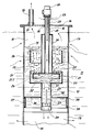
Nachfolgend wird ein Ausführungsbeispiel einer erfindungsgemäß ausgebildeten Anordnung anhand der beiliegenden Zeichnung näher erläutert, die einen schematischen Längsschnitt durch einen mit der Anordnung versehenen Brunnenschacht darstellt.An exemplary embodiment of an arrangement designed according to the invention is explained in more detail below with reference to the accompanying drawing, which shows a schematic longitudinal section through a well shaft provided with the arrangement.
Ein in Grundwasser führendes und beispielsweise durch Chlorkohlenwasserstoffe verseuchtes Erdreich 11 eingebrachter Brunnenschacht 10 ist teils mittels geschlossener Rohrabschnitte 12 und teils mittels wasserdurchlässiger Siebrohrabschnitte 13 ausgekleidet. Das obere Ende des Brunnenschachtes 10 ist durch einen Deckel 14 verschlossen. Im Deckel 14 ist eine zentrale Öffnung 15 für den freien Durchgang eines zentralen Rohres 16 und eine außermittige Öffnung 17 für ein Absaugrohr ausgebildet. DasA
Absaugrohr 18 führt zu einem nicht dargestellten Ventilator, mit welchem im Brunnenschacht oberhalb des sich dort ausbildenden Grundwasserspiegels 19 ein Unterdruck erzeugt wird.
Die in den Brunnenschacht 10 eingebrachte Anordnung zum Austreiben leichtflüchtiger Verunreinigungen aus dem sich im Brunnenschacht sammelnden Grundwasser 20 besteht in erster Linie aus einem Düsenkörper 21, dessen obere Begrenzungswandung 21.1 mit Düsenöffnungen 22 versehen ist. Der Düsenkörper 21 ist am unteren Ende des zentralen Rohres 16 befestigt, durch welches Luft durch obere äußere Öffnungen 23 bis in den Innenraum 24 des Düsenkörpers einströmen kann, die dann unter der Wirkung des oberhalb des Grundwasserspiegels 19 erzeugten Unterdruckes 10 durch die Düsenöffnungen 22 hindurch in Form feiner Bläschen 25 durch das Grundwasser 20 nach oben steigt. Um das zentrale Rohr 16 herum ist ein ringförmiger Schwimmkörper 26 ausgebildet, der den Düsenkörper 21 schwimmend in einem gewünschten Abstand vom Flüssigkeitsspiegel 19 hält.The arrangement introduced into the
Das zentrale Rohr 16 findet unterhalb des Düsenkörpers 21 eine Fortsetzung in einem ganz im Grundwasserbereich befindlichen zentralen Rohrabschnitt 27. In diesem Rohrabschnitt ist eine Förderschraube 28 angeordnet. Die Förderschraube 28 ist auf einer Welle 29 befestigt, die durch den Rohrabschnitt 27, den Düsenkörper 21 und das Rohr 16 hindurchgeführt und von einem Antriebsmotor 30 angetrieben ist, der auf das obere äußere Ende des Rohres 16 aufgesetzt ist.The
Das Rohr 16 und der Rohrabschnitt 27 können auch einstückig aus einem durchgehenden Rohr bestehen, das im Bereich des Düsenkörpers 21 Luftaustrittsöffnungen und unterhalb davon Grundwasser-Durchtrittsöffnungen aufweisen müßte. Beim dargestellten Ausführungsbeispiel ist der untere Rohrabschnitt in einer zentralen Wasserdurchtrittsöffnung 31 einer Bodenwandung 32 eines Leitringes 33 befestigt, der mit Abstand konzentrisch zum Düsenkörper 21 verläuft und über nicht dargestellte Haltestege am Düsenkörper 21 befestigt ist. Oberhalb des Düsenkörpers 21 ist außerdem ein Leitring 34 konzentrisch zum Rohr 26 angeordnet und über einzelne und nicht dargestellte Distanzstege am Schwimmkörper 26 befestigt.The
Der Rohrabschnitt 27 ist durch eine zentrale Öffnung 35 eines in den Brunnenschacht 10 eingebrachten Zwischenbodens 36 frei beweglich hindurchgeführt. Der Zwischenboden 36 ist topfartig gestaltet. Seine parallel zu den Schachtwandungen verlaufende Topfwandung 37 ist außen mit zwei aufblasbaren Klemmschläuchen 38 versehen, die über nicht dargestellte Schlauchleitungen zur Befestigung des Zwischenbodens 36 an der Brunnenschachtwandung aufblasbar sind.The
Strömungspfeile zeigen in der Anordnung und im Brunnenschacht das durch die Unterdruckbildung bewirkte Hindurchströmen von Luft sowie das durch die Unterdruckbildung im Brunnenschacht erzielte Strömen des Grundwassers durch die Siebwandungsteile 13 des Brunnenschachtes hindurch und innerhalb des Brunnenschachtes an, wo durch die Förderschraube 28 eine Vertikalströmung des Grundwassers verstärkt wird. In der Zeichnung ist ein Absaugen von Grundwasser aus dem oberhalb des Siebkörpers 21 befindlichen Reinigungsbereich durch den Rohrabschnitt 27 nach unten angedeutet. Durch eine Drehrichtungsumkehr der Förderschraube 28 kann aber auch ein Hochfördern von Grundwasser von unterhalb des Zwischenbodens 36 nach oben in den Reinigungsbereich der Anordnung bewirkt werden. Im Düsenkörper können zusätzlich außermittig zusätzliche Düsenschächte angeordnet werden, wie sie in der DE-PS 38 11 962 dargestellt und beschrieben sind.Flow arrows in the arrangement and in the well shaft indicate the flow of air caused by the vacuum formation and the flow of groundwater achieved by the vacuum formation in the well shaft through the
Claims (7)
- Arrangement for the expulsion of volatile impurities from groundwater and the soil it flows through by way of producing a subpressure in a wellshaft (10) which is driven into the area of soiled groundwater and by feeding a gas, in particular fresh air, to below the water level (19) in the wellshaft, comprising a nozzle body (21), which is arranged below the water level (19) and which defines an air chamber (24) and which is supported by a floating body (26), for the distribution of the delivered gas over the wellshaft cross-section via an upper defining wall of the nozzle body (21) with nozzle openings (22), and with a pipe (16) for the supply of air, which is guided centrally to the nozzle body and which is firmly connected to the nozzle body (21) and which has in the area of the air chamber (24) of the nozzle body (21) at least one air-outlet opening, and with a pipe which is located in its entirety in the groundwater area and which extends in the longitudinal direction of the shaft for ducting water in the shaft, characterised in that the water-ducting pipe is arranged as a downwardly open extension pipe area (27) to the air-feed pipe (16), which is downwardly guided to the outside via the nozzle body (21), that in said extension pipe (27) is arranged a conveyer propeller (28) which is operated in both conveying directions, and that the extension pipe (27) is provided in the area between the nozzle body (21) and the conveyer propeller (28) with at least one additional water-passage opening (31) which is positioned in the groundwater area.
- Arrangement according to claim 1, characterised in that the conveyer propeller (28) is arranged on a shaft (29), which is concentrically guided in the pipe (16, 27) and connected to a motor (30) which is placed on the top end of the pipe.
- Arrangement according to claim 1 or 2, characterised in that the extension pipe (27) is passed through an intermediate floor (36) arranged in the wellshaft (10).
- Arrangement according to claim 3, characterised in that the intermediate floor (36) is formed by a troughlike insert comprising outer fixing elements (38) and an opening (35) for displaceable passage of the extension pipe (27).
- Arrangement according to claim 4, characterised in that at least one inflatable clamping hose (38) is attached as a fixing element to the outer trough wall (37).
- Arrangement according to one of claims 1 to 5, characterised in that, in addition to a guide ring (34), which is fixedly and concentrically arranged above the nozzle body (21) and at a distance therefrom, is concentrically and at a distance from the nozzle body (21) additionally arranged a second guide ring (33), which is at the bottom connected to the extension pipe (27) by means of a bottom (32) which extends at a distance from the nozzle body (21).
- Arrangement according to one of claims 1 to 6, characterised in that the floating body (26) is an annular element which is arranged concentrically to the pipe (16) and/or to the extension pipe (27).
Priority Applications (1)
| Application Number | Priority Date | Filing Date | Title |
|---|---|---|---|
| AT90904820T ATE101801T1 (en) | 1989-04-05 | 1990-03-24 | ARRANGEMENT FOR DRIVING VOLATILE POLLUTANTS FROM GROUNDWATER. |
Applications Claiming Priority (2)
| Application Number | Priority Date | Filing Date | Title |
|---|---|---|---|
| DE3910990 | 1989-04-05 | ||
| DE3910990A DE3910990C1 (en) | 1989-04-05 | 1989-04-05 |
Publications (2)
| Publication Number | Publication Date |
|---|---|
| EP0466721A1 EP0466721A1 (en) | 1992-01-22 |
| EP0466721B1 true EP0466721B1 (en) | 1994-02-23 |
Family
ID=6377903
Family Applications (1)
| Application Number | Title | Priority Date | Filing Date |
|---|---|---|---|
| EP90904820A Expired - Lifetime EP0466721B1 (en) | 1989-04-05 | 1990-03-24 | Device for removing highly volatile impurities from the ground water |
Country Status (5)
| Country | Link |
|---|---|
| US (1) | US5171103A (en) |
| EP (1) | EP0466721B1 (en) |
| DE (1) | DE3910990C1 (en) |
| ES (1) | ES2049470T3 (en) |
| WO (1) | WO1990011811A1 (en) |
Families Citing this family (17)
| Publication number | Priority date | Publication date | Assignee | Title |
|---|---|---|---|---|
| DE4017642C1 (en) * | 1990-05-31 | 1991-12-12 | Santec Gmbh Ingenieurbuero Fuer Sanierungstechnologien, 1000 Berlin, De | |
| DE4027304C2 (en) * | 1990-08-29 | 1993-12-09 | Ieg Ind Engineering Gmbh | Arrangement for expelling volatile contaminants from the groundwater |
| DE4039824C1 (en) * | 1990-12-13 | 1991-12-19 | Ieg - Industrie-Engineering Gmbh, 7410 Reutlingen, De | |
| DE4204991A1 (en) * | 1991-12-24 | 1993-07-01 | Ieg Ind Engineering Gmbh | METHOD AND DEVICE FOR INFLUENCING LIQUID IN THE GROUND |
| DE4204059C2 (en) * | 1992-02-07 | 1994-05-05 | Koester Hans Herbert Dipl Geol | Remediation wells for removing groundwater contamination |
| DE4204990C2 (en) * | 1992-02-19 | 1994-01-27 | Ieg Ind Engineering Gmbh | Method and arrangement for dispensing liquids and / or gases, in particular oil, held in layers of earth or rock |
| DE4227570C1 (en) * | 1992-05-29 | 1993-09-30 | Ieg Ind Engineering Gmbh | Arrangement for expelling volatile contaminants on the spot |
| DE4218255A1 (en) * | 1992-06-03 | 1993-12-09 | Ieg Ind Engineering Gmbh | Process for flushing out dirt present in the ground |
| US5439594A (en) * | 1993-06-23 | 1995-08-08 | Geraghty & Miller, Inc. | Method for subsurface vapor extraction |
| US5383747A (en) * | 1993-08-23 | 1995-01-24 | International Technology Corporation | System for treating a subterranean formation having an aquifer contaminated with organics |
| US5613242A (en) * | 1994-12-06 | 1997-03-18 | Oddo; John E. | Method and system for disposing of radioactive solid waste |
| US5795474A (en) * | 1995-03-06 | 1998-08-18 | Tolan; Peter J. | Method and apparatus for the separation of hazardous waste from groundwater |
| US5622450A (en) * | 1995-03-24 | 1997-04-22 | Grant, Jr.; Richard P. | Pressure extraction process for removing soil and groundwater contaminants |
| US6143177A (en) | 1995-04-11 | 2000-11-07 | Arcadis Geraghty & Miller, Inc. | Engineered in situ anaerobic reactive zones |
| US6007274A (en) * | 1997-05-19 | 1999-12-28 | Arcadis Geraghty & Miller | In-well air stripping, oxidation, and adsorption |
| US6116816A (en) | 1998-08-26 | 2000-09-12 | Arcadis Geraghty & Miller, Inc. | In situ reactive gate for groundwater remediation |
| US8101089B2 (en) | 2007-08-15 | 2012-01-24 | Liquid Separation Technologies And Equipment, Llc | Apparatus for aeration of contaminated liquids |
Family Cites Families (8)
| Publication number | Priority date | Publication date | Assignee | Title |
|---|---|---|---|---|
| GB782823A (en) * | 1953-08-04 | 1957-09-11 | Smith Paper Mills Ltd Howard | Method and apparatus for separating dirt from aqueous suspensions of pulp fibres |
| DE1097449B (en) * | 1956-03-03 | 1961-01-19 | C Aug Schmidt Soehne | Thermal deaerator with vapor condenser for liquids, especially for boiler feed water |
| US4045336A (en) * | 1974-08-23 | 1977-08-30 | Pauli Henrik Isteri | Method and device for oxygenating water with vibrations and under pressure strokes |
| US4632601A (en) * | 1985-11-01 | 1986-12-30 | Kuwada James T | System and method for disposal of noncondensable gases from geothermal wells |
| DE3811962C1 (en) * | 1988-04-11 | 1989-02-16 | Ieg - Industrie-Engineering Gmbh, 7410 Reutlingen, De | Arrangement for expelling highly volatile impurities from ground water |
| DE3805200C1 (en) * | 1988-02-19 | 1988-09-29 | Ieg - Industrie-Engineering Gmbh, 7410 Reutlingen, De | Arrangement for expelling readily volatile impurities from groundwater |
| US4850745A (en) * | 1988-06-17 | 1989-07-25 | Sybron Chemicals, Inc. | Bioremediation system |
| DE8808089U1 (en) * | 1988-06-23 | 1988-10-06 | Ieg - Industrie-Engineering Gmbh, 7410 Reutlingen, De |
-
1989
- 1989-04-05 DE DE3910990A patent/DE3910990C1/de not_active Expired
-
1990
- 1990-03-24 ES ES90904820T patent/ES2049470T3/en not_active Expired - Lifetime
- 1990-03-24 US US07/768,633 patent/US5171103A/en not_active Expired - Fee Related
- 1990-03-24 EP EP90904820A patent/EP0466721B1/en not_active Expired - Lifetime
- 1990-03-24 WO PCT/EP1990/000479 patent/WO1990011811A1/en active IP Right Grant
Also Published As
| Publication number | Publication date |
|---|---|
| EP0466721A1 (en) | 1992-01-22 |
| US5171103A (en) | 1992-12-15 |
| DE3910990C1 (en) | 1989-12-21 |
| WO1990011811A1 (en) | 1990-10-18 |
| ES2049470T3 (en) | 1994-04-16 |
Similar Documents
| Publication | Publication Date | Title |
|---|---|---|
| EP0466721B1 (en) | Device for removing highly volatile impurities from the ground water | |
| DE3026519C2 (en) | Facility for the regeneration of silted water | |
| EP0486976B1 (en) | Device for the purification of polluted ground water | |
| EP1322533B1 (en) | Self-cleaning oscillating conveyor for deburring, dedusting and the onward transport of small parts | |
| EP0166017B1 (en) | Apparatus for the separation of mixing materials | |
| DE19501034C2 (en) | Device for separating floating and suspended matter from a liquid | |
| DE2519135C3 (en) | Cleaning system for impact cleaning of contaminated, granular material | |
| DE4214318C1 (en) | Device for skimming essentially organic components contained in fresh water or sea water | |
| DE1571759A1 (en) | Gas scrubber | |
| CH638968A5 (en) | CARPET DRAINAGE UNIT. | |
| DE2745141C3 (en) | dust filter | |
| DE4040820A1 (en) | DEVICE FOR CLEANING EXAMPLE OF GROUNDWATER INFLUENCED WITH POLLUTANTS | |
| AT406343B (en) | DEVICE FOR TREATING A LIQUID, IN PARTICULAR FOR PURIFYING WATER | |
| DE4129511C2 (en) | Device for cleaning groundwater by stripping with a gas, especially air | |
| EP0752242A2 (en) | Whirlpool bath | |
| DE4202814A1 (en) | Ground water cleaner - has injector tube within the well tube below pressurised stripping gas | |
| DE2419471A1 (en) | Sieve, especially for a slaughterhouse | |
| DE3408759A1 (en) | METHOD AND DEVICE FOR BIOLOGICAL WASTE WATER TREATMENT | |
| DE102007017447A1 (en) | Tank for breeding and fattening of fish, has dissipating device dissipating sediments, and lifting device conveying tank water into or below water surface under enrichment with oxygen from area of tank near base | |
| AT377743B (en) | DEVICE FOR AERATING WATER | |
| DE1958273A1 (en) | Vertical shaft surface aerator | |
| DE1952507C (en) | Wet dedusting system | |
| DE1933624C (en) | ||
| CH447115A (en) | Continuous filtering device for liquids | |
| DE2724471C2 (en) | Device for swirling and treating water |
Legal Events
| Date | Code | Title | Description |
|---|---|---|---|
| PUAI | Public reference made under article 153(3) epc to a published international application that has entered the european phase |
Free format text: ORIGINAL CODE: 0009012 |
|
| 17P | Request for examination filed |
Effective date: 19910919 |
|
| AK | Designated contracting states |
Kind code of ref document: A1 Designated state(s): AT CH DK ES FR GB IT LI NL SE |
|
| 17Q | First examination report despatched |
Effective date: 19920701 |
|
| RBV | Designated contracting states (corrected) |
Designated state(s): AT CH ES FR GB IT LI NL SE |
|
| GRAA | (expected) grant |
Free format text: ORIGINAL CODE: 0009210 |
|
| AK | Designated contracting states |
Kind code of ref document: B1 Designated state(s): AT CH ES FR GB IT LI NL SE |
|
| REF | Corresponds to: |
Ref document number: 101801 Country of ref document: AT Date of ref document: 19940315 Kind code of ref document: T |
|
| GBT | Gb: translation of ep patent filed (gb section 77(6)(a)/1977) |
Effective date: 19940311 |
|
| REG | Reference to a national code |
Ref country code: ES Ref legal event code: FG2A Ref document number: 2049470 Country of ref document: ES Kind code of ref document: T3 |
|
| ITF | It: translation for a ep patent filed |
Owner name: STUDIO APRA' BREVETTI |
|
| ET | Fr: translation filed | ||
| PLBE | No opposition filed within time limit |
Free format text: ORIGINAL CODE: 0009261 |
|
| STAA | Information on the status of an ep patent application or granted ep patent |
Free format text: STATUS: NO OPPOSITION FILED WITHIN TIME LIMIT |
|
| EAL | Se: european patent in force in sweden |
Ref document number: 90904820.9 |
|
| PGFP | Annual fee paid to national office [announced via postgrant information from national office to epo] |
Ref country code: CH Payment date: 19950203 Year of fee payment: 6 |
|
| PGFP | Annual fee paid to national office [announced via postgrant information from national office to epo] |
Ref country code: SE Payment date: 19950207 Year of fee payment: 6 |
|
| 26N | No opposition filed | ||
| PGFP | Annual fee paid to national office [announced via postgrant information from national office to epo] |
Ref country code: ES Payment date: 19950222 Year of fee payment: 6 |
|
| PGFP | Annual fee paid to national office [announced via postgrant information from national office to epo] |
Ref country code: FR Payment date: 19950228 Year of fee payment: 6 |
|
| PGFP | Annual fee paid to national office [announced via postgrant information from national office to epo] |
Ref country code: GB Payment date: 19950314 Year of fee payment: 6 |
|
| PGFP | Annual fee paid to national office [announced via postgrant information from national office to epo] |
Ref country code: AT Payment date: 19950321 Year of fee payment: 6 |
|
| PGFP | Annual fee paid to national office [announced via postgrant information from national office to epo] |
Ref country code: NL Payment date: 19950331 Year of fee payment: 6 |
|
| PG25 | Lapsed in a contracting state [announced via postgrant information from national office to epo] |
Ref country code: GB Effective date: 19960324 Ref country code: AT Effective date: 19960324 |
|
| PG25 | Lapsed in a contracting state [announced via postgrant information from national office to epo] |
Ref country code: SE Effective date: 19960325 Ref country code: ES Free format text: LAPSE BECAUSE OF NON-PAYMENT OF DUE FEES Effective date: 19960325 |
|
| PG25 | Lapsed in a contracting state [announced via postgrant information from national office to epo] |
Ref country code: LI Effective date: 19960331 Ref country code: CH Effective date: 19960331 |
|
| PG25 | Lapsed in a contracting state [announced via postgrant information from national office to epo] |
Ref country code: NL Effective date: 19961001 |
|
| GBPC | Gb: european patent ceased through non-payment of renewal fee |
Effective date: 19960324 |
|
| REG | Reference to a national code |
Ref country code: CH Ref legal event code: PL |
|
| PG25 | Lapsed in a contracting state [announced via postgrant information from national office to epo] |
Ref country code: FR Effective date: 19961129 |
|
| NLV4 | Nl: lapsed or anulled due to non-payment of the annual fee |
Effective date: 19961001 |
|
| EUG | Se: european patent has lapsed |
Ref document number: 90904820.9 |
|
| REG | Reference to a national code |
Ref country code: FR Ref legal event code: ST |
|
| REG | Reference to a national code |
Ref country code: ES Ref legal event code: FD2A Effective date: 19990301 |
|
| PG25 | Lapsed in a contracting state [announced via postgrant information from national office to epo] |
Ref country code: IT Free format text: LAPSE BECAUSE OF NON-PAYMENT OF DUE FEES;WARNING: LAPSES OF ITALIAN PATENTS WITH EFFECTIVE DATE BEFORE 2007 MAY HAVE OCCURRED AT ANY TIME BEFORE 2007. THE CORRECT EFFECTIVE DATE MAY BE DIFFERENT FROM THE ONE RECORDED. Effective date: 20050324 |