EP0466349B1 - String doffer mechanism - Google Patents
String doffer mechanism Download PDFInfo
- Publication number
- EP0466349B1 EP0466349B1 EP91305648A EP91305648A EP0466349B1 EP 0466349 B1 EP0466349 B1 EP 0466349B1 EP 91305648 A EP91305648 A EP 91305648A EP 91305648 A EP91305648 A EP 91305648A EP 0466349 B1 EP0466349 B1 EP 0466349B1
- Authority
- EP
- European Patent Office
- Prior art keywords
- doffer
- frame
- elements
- mechanism according
- frames
- Prior art date
- Legal status (The legal status is an assumption and is not a legal conclusion. Google has not performed a legal analysis and makes no representation as to the accuracy of the status listed.)
- Expired - Lifetime
Links
Images


Classifications
-
- A—HUMAN NECESSITIES
- A24—TOBACCO; CIGARS; CIGARETTES; SIMULATED SMOKING DEVICES; SMOKERS' REQUISITES
- A24B—MANUFACTURE OR PREPARATION OF TOBACCO FOR SMOKING OR CHEWING; TOBACCO; SNUFF
- A24B1/00—Preparation of tobacco on the plantation
- A24B1/04—Sifting, sorting, cleaning or removing impurities from tobacco
-
- A—HUMAN NECESSITIES
- A24—TOBACCO; CIGARS; CIGARETTES; SIMULATED SMOKING DEVICES; SMOKERS' REQUISITES
- A24B—MANUFACTURE OR PREPARATION OF TOBACCO FOR SMOKING OR CHEWING; TOBACCO; SNUFF
- A24B5/00—Stripping tobacco; Treatment of stems or ribs
- A24B5/08—Stripping tobacco; Treatment of stems or ribs by cutting-off, shaving off, pressing flat the thick parts of stems or ribs
-
- A—HUMAN NECESSITIES
- A24—TOBACCO; CIGARS; CIGARETTES; SIMULATED SMOKING DEVICES; SMOKERS' REQUISITES
- A24B—MANUFACTURE OR PREPARATION OF TOBACCO FOR SMOKING OR CHEWING; TOBACCO; SNUFF
- A24B3/00—Preparing tobacco in the factory
- A24B3/18—Other treatment of leaves, e.g. puffing, crimpling, cleaning
Definitions
- This invention relates to a string doffer mechanism for removal and separation of undesirable objects such as string and dirt from a material, such as tobacco, before end products can be made from the material.
- the tobacco is transferred across a series of rotating rollers, or "doffer elements", which are covered by cleaning elements such as brushes.
- the cleaning elements may be a material containing densely packed resilient hook members, such as Velcro®.
- the contaminants contained in the tobacco become entwined in the rotating brushes or the Velcro attached to the individual doffer elements.
- the tobacco is transferred to a separate device, such as a conveyor, and moved to other locations for further processing or storage.
- the cleaning brushes or the Velcro must frequently be cleaned of contaminants and periodically replaced.
- Velcro® employed as the cleaning means
- the effectiveness of the cleaning surface is reduced.
- the trapped contaminants must be removed.
- various portions of the mechanism, such as the doffer elements require maintenance at unpredictable times. Cleaning, replacement, and maintenance require that the mechanism be inoperable and result in system down time. Maintenance of the mechanism and doffer elements that requires removal of the doffer elements is complicated by the fact that the doffer elements disclosed in the prior art each weighs a great deal.
- variable spacings between the doffer elements provide optimal cleaning for tobacco known to contain certain types of contaminants.
- different grades of tobacco which are of differing densities, require different operating parameters in order to be properly cleaned. For example, testing on Bright tobacco has revealed that a 2-inch horizontal gap between all doffer elements results in optimal separation. Elevation changes between doffer elements are not necessary for Bright tobacco. Testing on Bright has also indicated that up to 50% of entrained contaminants can be removed when the doffer elements are rotated at a speed of 150 rpm and the tobacco feed rate is 8,000 pounds per hour.
- the mechanism's operating conditions must be adjustable in order to obtain optimal separation and removal of contaminants from different varieties of tobacco, as well as from other materials.
- US-A-973,228 discloses a tobacco cleaning machine in which tobacco passes through pairs of opposed rotating brushes.
- US-A-4,809,716 discloses a conventional string doffer in which a plurality of doffer elements are arranged in a frame.
- US-A-4,102,502 discloses a bed of rollers used to separate platelets from mined ore; and DE-A-2504875 discloses a further example of a tobacco cleaning machine.
- the present invention aims to overcome the limitations of the prior art described above and to provide a doffer mechanism and doffer elements which may be adjusted to the optimum operating conditions for the material being processed.
- a doffer mechanism for removing contaminants from a stream of material comprising a frame having at least two oppositely disposed sides, a plurality of doffer elements, each doffer element having two ends and an axis of rotation passing through the two ends, means for mounting the two ends of each of the doffer elements to opposite sides of the frame at positions along the sides of the frame, such that the doffer elements are mounted in a row across the frame and the axes of rotation of the plurality of doffer elements are substantially parallel, means for rotating the plurality of doffer elements about their respective axis of rotation, and means for adjusting the elevation above or below the frame of at least one of the doffer elements.
- the invention also provides a doffer mechanism for removing contaminants from a stream of material, comprising a frame having at least two oppositely disposed sides, a plurality of doffer elements, each doffer element having two ends and an axis of rotation passing through the two ends, means for mounting the two ends of each of the doffer elements to opposite sides of the frame at positions along the sides of the frame, such that the doffer elements are mounted in a row across the frame and the axes of rotation of the plurality of doffer elements are substantially parallel, means for rotating the plurality of doffer elements about their respective axis of rotation, and means for selectively adjusting the positions along the sides of the frame at which the ends of at least one doffer element are mounted to the frame.
- Embodiments of the invention have the advantage that variation in the operating conditions of the mechanism is possible.
- An embodiment of the invention permits for easy adjustment of the gap between successive doffer elements and easy adjustment of the elevation of individual doffer elements relative to the frame to optimize tobacco surface contact with the doffer cleaning means for various types and grades of tobacco.
- the frames of the mechanism of a preferred embodiment of the present invention may also be installed at an upwardly inclined angle if operating conditions so dictate.
- Preferred embodiments of the present invention may have the advantage of requiring a reduced system down time for cleaning and maintenance of the doffer mechanism and doffer elements.
- Preferred embodiments of the invention may also have the advantage of having lightweight doffer elements and a doffer mechanism which allows for easy removal of the doffer elements for maintenance as well as replacement of cleaning elements attached to the doffer elements.
- Preferred embodiments of the invention have the advantage of an improved drive design which may facilitate the aforementioned adjustments, cleaning, maintenance and replacement of the doffer elements and the cleaning means attached to the doffer elements.
- a doffer mechanism for the removal of contaminants from tobacco includes a plurality of doffer elements mounted parallel to one another within a frame, each doffer element having cleaning flights located thereon.
- the doffer elements are rotated about their axes in the same direction and are driven by a continuous chain which allows for easy individual adjustment of the gap between doffers.
- the elevation of one or more doffer elements above or below the frame may be readily and easily adjusted.
- a pair of frames is provided, each frame having a plurality of doffer elements.
- the pair of frames is connected to one another by a subframe such that each frame can be pivoted from a first, substantially horizontal position during which the doffer elements in that frame are operable, to a second, substantially upright position during which the doffer elements in that frame can be cleaned.
- FIG. 1 may depict a pair of frames which remain unconnected and a flop or pantleg gate.
- the gate can be used to direct the flow of the material to be cleaned to one frame while the other frame is idle and can be cleaned.
- the frames can be located parallel to one another or can be oppositely inclined from one another.
- the doffer elements are hollow and generally tubular in shape and have a cleaning surface affixed at various locations.
- a drive assembly for driving the doffer elements within the frame is also provided.
- the drive assembly comprises a continuous chain, a drive means such as a motor, a plurality of doffer sprockets attached to the doffer elements and a plurality of idler sprockets.
- the doffer sprockets engage the exterior side of the chain such that the doffer elements may be removed for cleaning and maintenance without disrupting the path of the chain.
- rotatable doffer elements 11 each include a hollow metal tube 17.
- the ends of doffer elements 11 are affixed to hollow metal shafts 16 and 18 by means of circular metal plates 20 located at each end of tube 17.
- Plates 20 are affixed to tube 17 by means of screws or a weld or any other means generally known in the art.
- Plate 20 supports the tube 17 and provides a means for affixing the shafts 16 and 18.
- Doffer sprocket 19 is affixed to shaft 18 so that rotation of doffer sprocket 19 will cause doffer element 11 to rotate about its longitudinal axis.
- hollow tube 17 of each doffer element 11 is preferably 37-1/2 inches long and is preferably 4 inches in diameter.
- the design of these doffer elements differs from other rotatable elements which are comprised of substantially solid metal.
- the doffer elements embodying the present invention weigh much less than those currently in use, while providing the required structural integrity and durability required of string doffer mechanisms.
- Flights 12 are attached along the length of the outer surface of the tube 17.
- flights 12 are hollow metal protuberances extending in a longitudinal direction along the tube 17.
- flights 12 consist of six 1-inch square paddles welded to each doffer at equal distances about the circumference of tube 17.
- Attached to the top surface of flights 12 is cleaning means 13. Attachment of the cleaning means 13 may be by any known means such as by adhesive. Screwing the cleaning means 13 onto the flight 12 by providing several screw holes in the flight and cleaning means prevents lifting while allowing for easy removal and replacement of cleaning means 13 and is thus preferred.
- cleaning means 13 consists of a hook material such as Velcro® and is attached only to the top surfaces of the flights. Most preferably, cleaning means 13 is white in color, thereby allowing for easy detection of contaminants which become entwined therein.
- all surfaces of flights 12 and all exposed surfaces of metal tube 17 may be covered with a cleaning means. However, because the tobacco tends to almost exclusively engage the top surfaces of the flights, covering only the top surfaces of the flights is preferred.
- Fig. 1(a) illustrates the preferred placement of cleaning means 13.
- Cleaning and replacement of the cleaning means is less expensive and time consuming when only the top surfaces of the flights are covered. Cleaning may be accomplished by hand using a spring steel curry comb and should be performed as often as possible to increase the efficiency of the mechanism.
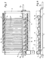
- the mechanism consists of a single doffer unit.
- the doffer unit consists of a frame 10 and doffer elements 11.
- Doffer elements 11 are generally cylindrical and rotate simultaneously in the direction of product flow.
- each doffer element 11 has a maximum length of 37 1/2 inches and a diameter of approximately 4 inches.
- doffer elements 11 are attached to frame 10 via shafts 16 and 18 by means of blocks 22-28.
- Blocks 22-28 may be fixedly mounted to frame 10, as was conventionally done prior to the present invention.
- the blocks may be slidably mounted to frame 10, as will be described below.
- bearing mounts 32 are attached to differing types of blocks 22-28, such as by bolts 35.
- Bearing mounts 32 support shafts 16 and 18 of doffer elements 11.
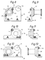
- the bearing mount and block design illustrated in Figs. 6-9 permits vertical or elevation adjustments to doffer elements 11.
- the terms "vertical” or “elevation” refer to the distance of the doffer element from an imaginary plane lying on the frame. Thus, if the frame is situated horizontally the “elevation" of the doffer element from the frame corresponds to its vertical distance from the frame.
- Figs. 6 and 7 show adjustable block 22 that supports shaft 16. Adjustable block 22 is located on the side of the mechanism opposite the driving means for the doffer elements 11. Figs.
- FIG. 8 and 9 show drive side adjustable block 24 that supports shaft 18 and includes sprocket 34 that is rotatably affixed to block 24 using conventional means. Doffer sprocket 19 is also shown. Sprocket 34, which is shown in Fig. 8 and Fig. 3, is not shown in Fig. 9 for clarity.
- the blocks 22 and 24 are provided with a plurality of pairs of holes 23.
- the elevation of doffer element 11 relative to frame 10 can be adjusted.
- the range of elevation adjustment is limited to two inches.
- the blocks shown in Figs. 6-9 can be adjusted to five different elevations.
- Figs. 10-13 operate in the same manner as those illustrated in Figs. 6-9. However, because blocks 26 and 28 do not permit vertical adjustment to doffer elements 11, they contain only one pair of holes for receiving bearing mount 32 as opposed to the plurality of hole pairs contained in adjustable block 22 and drive side adjustable block 24.
- Figs. 10 and 11 show block 26 which supports shaft 16 in bearing mount 32. Block 26 is located on the side of the mechanism opposite the driving means for the doffer elements 11.
- Figs. 12 and 13 show drive side block 28 which supports drive shaft 18.
- Drive side block 28 includes sprocket 34 that is rotatably affixed to block 28 using conventional means. Doffer sprocket 19 is shown. Sprocket 34, which is shown in Fig. 12 and Fig. 3, is not shown in Fig. 13 for clarity.
- the means for attaching blocks 22-28 to frame 10 provides for continuously variable adjustment of the horizontal gap between successive doffer elements 11.
- the frame 10 is provided with T-shaped groove 27 along the length of each of its sides.
- Blocks 22-28 can be slidably mounted to frame 10 by means of two T-bolt 37, the head of which fits into T-shaped groove 27.
- nut 36 of T-bolt 37 is loosened and block 22, 24, 26, or 28 is moved along the T-shaped groove located within frame 10 to its desired position.
- nut 36 of T-bolt 37 is re-tightened.
- blocks 22-28 and doffer elements 11 which are supported by blocks 22-28 can be positioned at any particular position along frame 10.
- each block is fastened to frame 10 by two T-bolts 37 and two nuts 36.
- each block 22-28 can be slid between 0 and 3 inches along the frame 10.
- the doffer elements 11 are rotatable about their axes in bearings 32 which are mounted on frame 10 by blocks 22-28.
- Doffer sprockets 19 of doffer elements 11 are driven by a continuous chain 15, as illustrated in Fig. 4.
- chain 15 is not illustrated in Fig. 3, which is a top view of frame 10 with doffer elements 11.
- Chain 15 is driven by drive motor/gear reducer 14 which is located on the feed end of the doffer unit.
- Chain 15 passes around guide sprockets 21 which are located beneath frame 10.
- Guide sprockets 21 aid in the maintenance of the proper amount of tension in chain 15.
- the path of chain 15 runs below the doffer sprockets 19 mounted on each shaft 18 and over idler sprockets 34 mounted to blocks 22-28 by means of idler sprocket bearings.
- doffer sprockets 19 are located outside of the loop formed by continuous chain 15.
- This drive arrangement permits doffer elements 11 to be removed for maintenance or for horizontal or vertical adjustment without disturbing the path of chain 15.
- bearing mounts 32 are unbolted and doffer element 11 is lifted away from blocks 22, 24, 26, or 28.
- a tensioned belt can be substituted for chain 15, and the sprockets can be replaced with drums.
- Chain 15 and sprockets are preferred, however.
- frame 10 supports nine doffer elements 11. It has been found that contaminant removal efficiency increases as the doffer element surface area increases due to improved tobacco distribution and contact with the cleaning means; therefore, it is advantageous to use a plurality of doffer elements.
- the mechanism is provided with adjustable blocks 22 and drive side adjustable blocks 24 for adjusting the vertical elevation of doffer elements 11.
- Adjustable blocks 22 and drive side adjustable blocks are paired opposite one another along frame 10 only at specific locations.
- Blocks 22 and 24 are preferably installed at doffer element locations 4, 6 and 9, with location 1 at the feed end of the mechanism.
- the doffer mechanism embodying the present invention may have three separate designs: a right hand drive assembly, a left hand drive assembly, and a "flop" style assembly.
- the right hand and left hand drive assemblies consist of a single frame unit of doffers, as shown in Fig. 3. (Fig. 3 depicts the right hand drive assembly.)
- the single unit assemblies were created for low clearance installations. In order to suit the particular installation, these assemblies can have the drive assembly on the right or the left side.
- the flop style assembly as illustrated in Fig. 14, is essentially a utilization of both the right hand assembly and the left hand assembly held together by subframe 33.
- pivot means 39 which comprises stub shafts 39a, which are attached to the ends of frame 10, and bushing blocks 39b, which are attached to subframe 33.
- Pivot means 39 could also be any other pivoting arrangement known in the art.
- the flop assembly is preferred because the contaminant removal efficiency is much higher than for a single frame doffer unit. This is because the assembly can be cleaned more often without substantial down time.
- the doffer elements 11 can be regularly cleaned every 2-3 hours with minimum down time. As shown in Fig. 14, one doffer unit operates in a substantially horizontal position while the other doffer unit is cleaned or maintained in an upright position. Tilt bed motors 50 and gear boxes 51 are not shown in Fig. 14 for clarity.
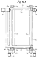
- FIG. 3 The top view of a frame 10 shown in Fig. 3 also shows stub shafts 39a. Also shown is motor/gear reducer 14, which is preferably positioned to counterbalance the weight of frame 10 and doffers 11 about pivot means 39.
- Fig. 14A shows a top view of frames 10a and 10b mounted on subframe 33. Doffer elements 11, mounting blocks 22-28, and the drive assembly are not shown. Bushing blocks 39b are attached to subframe 33 and support stub shafts 39a. Tilt bed motors 50 and conventional gear boxes 51 are also attached to subframe 33. Gear boxes 51, driven by motors 50, rotate stub shafts 39a to raise and lower frames 10a and 10b.
- frame 10a is shown in the horizontal position, whereas frame 10b is shown in the upright or vertical position.
- doffer units may be alternatively brought into and out of engagement by means of tilt bed motors 50 which cause frames 10 to rotate about pivot means 39.
- Pivot means 39 may be of any type generally known in the art.
- each unit is fully positively counterbalanced so that the mechanism's natural position is either up (the cleaning/maintenance position) or down (the operating position).
- the flop assembly is used in conjunction with a take away conveyor 41 located at the downstream end of the flop assembly for moving the cleaned tobacco on for further processing.
- Figs. 15-17 Other embodiments of the present invention are illustrated in Figs. 15-17.
- the mechanism may consist of a feed chute with a "pant leg” assembly 43 and opposing frames 10 containing rotating doffer elements 11.
- tobacco flows down one "leg” of chute 43, is processed through doffer elements 11 contained within one of the opposing frames 10 (not shown), and is moved on for further processing by conveyors 41. While tobacco is processed through one doffer unit, the other may be cleaned.
- Fig. 16 illustrates the same basic embodiment as shown in Fig. 15 with a single take away conveyor.
- the pant leg assembly is useful because it eliminates the need for a movable conveyor for dropping tobacco onto the middle of the first doffer element 11.
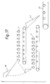
- Fig. 17 Another alternative is illustrated in Fig. 17.
- doffer units which are represented by doffers 11, are layered.
- This assembly makes use of a flop gate 45 and a drop chute 47.
- the flop gate 45 drops tobacco onto the upper doffer unit. After processing, tobacco travels through drop chute 47 onto take away conveyor 41.
- the lower doffer unit is in use and upper doffer unit can be cleaned, flop gate 45 swings downwardly to deliver tobacco to the lower doffer unit. There is no need to use drop chute 47 as tobacco directly travels to take away conveyor 41.
- the preferred use of the mechanism of the present invention relates to the removal of contaminants from a uniform flow of tobacco fed through the doffer elements, it is not limited to the purification of tobacco. Many types of materials can be purified using doffer elements in any of the embodiments described above.
Landscapes
- Agronomy & Crop Science (AREA)
- Life Sciences & Earth Sciences (AREA)
- Preliminary Treatment Of Fibers (AREA)
- Spinning Or Twisting Of Yarns (AREA)
- Socks And Pantyhose (AREA)
- Removal Of Floating Material (AREA)
- Undergarments, Swaddling Clothes, Handkerchiefs Or Underwear Materials (AREA)
- Manufacture Of Tobacco Products (AREA)
- Extraction Or Liquid Replacement (AREA)
- Chair Legs, Seat Parts, And Backrests (AREA)
- Bidet-Like Cleaning Device And Other Flush Toilet Accessories (AREA)
- Telephone Function (AREA)
- Yarns And Mechanical Finishing Of Yarns Or Ropes (AREA)
- Replacement Of Web Rolls (AREA)
- Electromagnets (AREA)
- Magnetic Heads (AREA)
- Cleaning In General (AREA)
- Treatment Of Fiber Materials (AREA)
- Processing Of Solid Wastes (AREA)
Priority Applications (2)
| Application Number | Priority Date | Filing Date | Title |
|---|---|---|---|
| EP96202045A EP0743019B1 (en) | 1990-07-09 | 1991-06-21 | String doffer mechanism |
| GR20000400641T GR3032945T3 (en) | 1990-07-09 | 2000-03-10 | String doffer mechanism |
Applications Claiming Priority (2)
| Application Number | Priority Date | Filing Date | Title |
|---|---|---|---|
| US550177 | 1990-07-09 | ||
| US07/550,177 US5211187A (en) | 1990-07-09 | 1990-07-09 | String doffer mechanism |
Related Child Applications (2)
| Application Number | Title | Priority Date | Filing Date |
|---|---|---|---|
| EP96202045A Division EP0743019B1 (en) | 1990-07-09 | 1991-06-21 | String doffer mechanism |
| EP96202045.9 Division-Into | 1996-07-18 |
Publications (3)
| Publication Number | Publication Date |
|---|---|
| EP0466349A2 EP0466349A2 (en) | 1992-01-15 |
| EP0466349A3 EP0466349A3 (en) | 1993-07-14 |
| EP0466349B1 true EP0466349B1 (en) | 1997-10-01 |
Family
ID=24196066
Family Applications (2)
| Application Number | Title | Priority Date | Filing Date |
|---|---|---|---|
| EP91305648A Expired - Lifetime EP0466349B1 (en) | 1990-07-09 | 1991-06-21 | String doffer mechanism |
| EP96202045A Expired - Lifetime EP0743019B1 (en) | 1990-07-09 | 1991-06-21 | String doffer mechanism |
Family Applications After (1)
| Application Number | Title | Priority Date | Filing Date |
|---|---|---|---|
| EP96202045A Expired - Lifetime EP0743019B1 (en) | 1990-07-09 | 1991-06-21 | String doffer mechanism |
Country Status (11)
| Country | Link |
|---|---|
| US (1) | US5211187A (tr) |
| EP (2) | EP0466349B1 (tr) |
| JP (1) | JPH04252165A (tr) |
| KR (1) | KR100200196B1 (tr) |
| AT (2) | ATE187609T1 (tr) |
| BR (1) | BR9102867A (tr) |
| DE (2) | DE69127784T2 (tr) |
| DK (2) | DK0743019T3 (tr) |
| ES (2) | ES2107442T3 (tr) |
| GR (2) | GR3025701T3 (tr) |
| TR (1) | TR26242A (tr) |
Families Citing this family (5)
| Publication number | Priority date | Publication date | Assignee | Title |
|---|---|---|---|---|
| DE19505259A1 (de) * | 1995-02-16 | 1996-08-22 | Koehl Maschbau Gmbh | Vorrichtung zum Entfernen von langfaserigen Fremdstoffen aus Tabak |
| US5769607A (en) * | 1997-02-04 | 1998-06-23 | Itt Automotive Electrical Systems, Inc. | High-pumping, high-efficiency fan with forward-swept blades |
| ATE311772T1 (de) * | 2003-03-22 | 2005-12-15 | Hauni Maschinenbau Ag | Vorrichtung zum entfernen von fremdstoffen aus tabak |
| EP1886587A1 (en) * | 2006-08-08 | 2008-02-13 | V.I.T. S.A. | Tobacco leave cleaning rollers from scrap and foreign materials |
| CN113424977B (zh) * | 2021-06-16 | 2023-02-03 | 张家口卷烟厂有限责任公司 | 一种真空回潮筐自动清扫装置 |
Citations (11)
| Publication number | Priority date | Publication date | Assignee | Title |
|---|---|---|---|---|
| BE376899A (tr) * | ||||
| GB1002355A (en) * | 1962-05-15 | 1965-08-25 | Welded And Allied Products Ltd | Improvements relating to roller conveyors |
| AU259866A (en) * | 1967-03-08 | 1968-09-12 | An improved screening mechanism | |
| US3724629A (en) * | 1971-11-16 | 1973-04-03 | W Collins | Roller assembly |
| US3848741A (en) * | 1973-06-22 | 1974-11-19 | Reserve Mining Co | Adjustable, sealed roll screen for classifying and conveying material-in-process such as taconite pellets |
| DE2504873A1 (de) * | 1975-02-06 | 1976-08-19 | Hauni Werke Koerber & Co Kg | Anlage zum pneumatischen beschicken tabakverarbeitender strangmaschinen |
| US3985233A (en) * | 1975-12-11 | 1976-10-12 | Weyerhaeuser Company | Vibratory seedling cleaner |
| DE2609812A1 (de) * | 1976-03-10 | 1977-09-22 | Hauni Werke Koerber & Co Kg | Verfahren und vorrichtung zum aussondern metallischer fremdkoerper aus einem foerdergut der tabakverarbeitenden industrie |
| FR2344474A1 (fr) * | 1976-03-17 | 1977-10-14 | Europ Levage Manutention | Portillon relevable pour transporteurs a rouleaux |
| US4102502A (en) * | 1976-12-10 | 1978-07-25 | W. R. Grace & Co. | Concentration of plate-shaped minerals |
| US4693356A (en) * | 1986-03-03 | 1987-09-15 | Pi May Yang | Structure of roller type conveyer |
Family Cites Families (10)
| Publication number | Priority date | Publication date | Assignee | Title |
|---|---|---|---|---|
| GB190526683A (en) * | 1905-12-21 | 1906-12-20 | Frederick Salomon | Improvements in or in connection with Apparatus for Preparing Tobacco Leaves. |
| US973228A (en) * | 1909-11-24 | 1910-10-18 | Charles Moses Spierer | Tobacco-cleaning machine. |
| US1831953A (en) * | 1930-05-10 | 1931-11-17 | Fonseca Andres Santalla | Tobacco cleaning machine |
| US2942607A (en) * | 1957-07-08 | 1960-06-28 | W I Skinner And Company | Machines for cleaning tobacco scrap |
| US3339258A (en) * | 1965-03-26 | 1967-09-05 | Int Harvester Co | Pressure roll and method of making |
| US3355758A (en) * | 1966-01-14 | 1967-12-05 | Gaylord J Clark | Rotary brush construction |
| US3412446A (en) * | 1966-08-24 | 1968-11-26 | Deere & Co | Roll construction |
| US4703538A (en) * | 1985-11-01 | 1987-11-03 | Silverstrone Catherine A | Cleaning tool |
| US4817639A (en) * | 1987-07-14 | 1989-04-04 | Caudill Charles R | Tobacco leaf cleaning device |
| US4809716A (en) * | 1988-03-31 | 1989-03-07 | Caudill Charles R | Tobacco leaf cleaning machine |
-
1990
- 1990-07-09 US US07/550,177 patent/US5211187A/en not_active Expired - Lifetime
-
1991
- 1991-06-21 ES ES91305648T patent/ES2107442T3/es not_active Expired - Lifetime
- 1991-06-21 AT AT96202045T patent/ATE187609T1/de not_active IP Right Cessation
- 1991-06-21 EP EP91305648A patent/EP0466349B1/en not_active Expired - Lifetime
- 1991-06-21 DK DK96202045T patent/DK0743019T3/da active
- 1991-06-21 DK DK91305648.7T patent/DK0466349T3/da active
- 1991-06-21 ES ES96202045T patent/ES2142540T3/es not_active Expired - Lifetime
- 1991-06-21 EP EP96202045A patent/EP0743019B1/en not_active Expired - Lifetime
- 1991-06-21 DE DE69127784T patent/DE69127784T2/de not_active Expired - Fee Related
- 1991-06-21 AT AT91305648T patent/ATE158693T1/de not_active IP Right Cessation
- 1991-06-21 DE DE69131854T patent/DE69131854T2/de not_active Expired - Fee Related
- 1991-07-08 BR BR919102867A patent/BR9102867A/pt not_active IP Right Cessation
- 1991-07-08 JP JP3264256A patent/JPH04252165A/ja active Pending
- 1991-07-09 TR TR91/0653A patent/TR26242A/tr unknown
- 1991-07-09 KR KR1019910011790A patent/KR100200196B1/ko not_active IP Right Cessation
-
1997
- 1997-12-17 GR GR970403352T patent/GR3025701T3/el unknown
-
2000
- 2000-03-10 GR GR20000400641T patent/GR3032945T3/el unknown
Patent Citations (11)
| Publication number | Priority date | Publication date | Assignee | Title |
|---|---|---|---|---|
| BE376899A (tr) * | ||||
| GB1002355A (en) * | 1962-05-15 | 1965-08-25 | Welded And Allied Products Ltd | Improvements relating to roller conveyors |
| AU259866A (en) * | 1967-03-08 | 1968-09-12 | An improved screening mechanism | |
| US3724629A (en) * | 1971-11-16 | 1973-04-03 | W Collins | Roller assembly |
| US3848741A (en) * | 1973-06-22 | 1974-11-19 | Reserve Mining Co | Adjustable, sealed roll screen for classifying and conveying material-in-process such as taconite pellets |
| DE2504873A1 (de) * | 1975-02-06 | 1976-08-19 | Hauni Werke Koerber & Co Kg | Anlage zum pneumatischen beschicken tabakverarbeitender strangmaschinen |
| US3985233A (en) * | 1975-12-11 | 1976-10-12 | Weyerhaeuser Company | Vibratory seedling cleaner |
| DE2609812A1 (de) * | 1976-03-10 | 1977-09-22 | Hauni Werke Koerber & Co Kg | Verfahren und vorrichtung zum aussondern metallischer fremdkoerper aus einem foerdergut der tabakverarbeitenden industrie |
| FR2344474A1 (fr) * | 1976-03-17 | 1977-10-14 | Europ Levage Manutention | Portillon relevable pour transporteurs a rouleaux |
| US4102502A (en) * | 1976-12-10 | 1978-07-25 | W. R. Grace & Co. | Concentration of plate-shaped minerals |
| US4693356A (en) * | 1986-03-03 | 1987-09-15 | Pi May Yang | Structure of roller type conveyer |
Also Published As
| Publication number | Publication date |
|---|---|
| DE69127784D1 (de) | 1997-11-06 |
| EP0743019A2 (en) | 1996-11-20 |
| EP0743019A3 (en) | 1997-11-12 |
| DK0743019T3 (da) | 2000-06-13 |
| EP0743019B1 (en) | 1999-12-15 |
| DE69131854D1 (de) | 2000-01-20 |
| ATE187609T1 (de) | 2000-01-15 |
| GR3032945T3 (en) | 2000-07-31 |
| ES2142540T3 (es) | 2000-04-16 |
| EP0466349A3 (en) | 1993-07-14 |
| DK0466349T3 (da) | 1997-11-03 |
| DE69131854T2 (de) | 2000-07-06 |
| ES2107442T3 (es) | 1997-12-01 |
| JPH04252165A (ja) | 1992-09-08 |
| US5211187A (en) | 1993-05-18 |
| TR26242A (tr) | 1995-02-15 |
| ATE158693T1 (de) | 1997-10-15 |
| GR3025701T3 (en) | 1998-03-31 |
| DE69127784T2 (de) | 1998-04-09 |
| EP0466349A2 (en) | 1992-01-15 |
| KR920002056A (ko) | 1992-02-28 |
| BR9102867A (pt) | 1992-02-04 |
| KR100200196B1 (ko) | 1999-06-15 |
Similar Documents
| Publication | Publication Date | Title |
|---|---|---|
| EP0773070B1 (en) | A waste paper sorting conveyor for sorting waste paper from waste cardboard | |
| CA1166113A (en) | Feeder idler drum shaft with removable extensions | |
| AU2018351472A1 (en) | Screen belt unit for a harvesting machine and associated shutter unit | |
| EP0466349B1 (en) | String doffer mechanism | |
| US11596168B2 (en) | Modular nut cleaning plant | |
| KR101133143B1 (ko) | 선별기의 이송장치 | |
| EP0790945A1 (en) | A stabiliser unit for conveyor belts | |
| EP0527640B1 (en) | Improvements in or relating to a device for feeding objects | |
| CN111545457A (zh) | 大蒜分瓣分级机械化装置及其控制方法 | |
| US4566471A (en) | Cutting apparatus | |
| US5537809A (en) | Seed cotton module handler with trash separator | |
| RU2288621C2 (ru) | Устройство подачи в зону резания резальной машины органических материалов растительного происхождения, в частности табака | |
| US5767421A (en) | Belt conveyor cross-stream sampling system | |
| US4278097A (en) | Husking machine | |
| US6062394A (en) | Modular wood particle screen | |
| CN208635537U (zh) | 粉末冶金烘烤设备给料系统 | |
| CN212244976U (zh) | 一种鸡蛋传送输入装置 | |
| US4744714A (en) | Bin vibrating discharge device for surge or blending bins or the like | |
| CN211168706U (zh) | 砂料传送带 | |
| CN208326435U (zh) | 一种刮板清料机 | |
| CN112975536A (zh) | 一种数控机床自动化上料装置 | |
| US5765694A (en) | Seed cotton module handler and trash separator | |
| CN219965602U (zh) | 一种可调式水果大小分拣及异物除杂装置 | |
| KR102453410B1 (ko) | 농산물 정렬공급장치 | |
| CN214555088U (zh) | 一种大米米垢清理装置 |
Legal Events
| Date | Code | Title | Description |
|---|---|---|---|
| PUAI | Public reference made under article 153(3) epc to a published international application that has entered the european phase |
Free format text: ORIGINAL CODE: 0009012 |
|
| AK | Designated contracting states |
Kind code of ref document: A2 Designated state(s): AT BE CH DE DK ES FR GB GR IT LI NL SE |
|
| PUAL | Search report despatched |
Free format text: ORIGINAL CODE: 0009013 |
|
| AK | Designated contracting states |
Kind code of ref document: A3 Designated state(s): AT BE CH DE DK ES FR GB GR IT LI NL SE |
|
| 17P | Request for examination filed |
Effective date: 19940107 |
|
| 17Q | First examination report despatched |
Effective date: 19960110 |
|
| GRAG | Despatch of communication of intention to grant |
Free format text: ORIGINAL CODE: EPIDOS AGRA |
|
| GRAH | Despatch of communication of intention to grant a patent |
Free format text: ORIGINAL CODE: EPIDOS IGRA |
|
| GRAH | Despatch of communication of intention to grant a patent |
Free format text: ORIGINAL CODE: EPIDOS IGRA |
|
| GRAA | (expected) grant |
Free format text: ORIGINAL CODE: 0009210 |
|
| AK | Designated contracting states |
Kind code of ref document: B1 Designated state(s): AT BE CH DE DK ES FR GB GR IT LI NL SE |
|
| DX | Miscellaneous (deleted) | ||
| REF | Corresponds to: |
Ref document number: 158693 Country of ref document: AT Date of ref document: 19971015 Kind code of ref document: T |
|
| REG | Reference to a national code |
Ref country code: CH Ref legal event code: EP |
|
| REG | Reference to a national code |
Ref country code: DK Ref legal event code: T3 |
|
| REF | Corresponds to: |
Ref document number: 69127784 Country of ref document: DE Date of ref document: 19971106 |
|
| ET | Fr: translation filed | ||
| REG | Reference to a national code |
Ref country code: CH Ref legal event code: NV Representative=s name: BOVARD AG PATENTANWAELTE |
|
| REG | Reference to a national code |
Ref country code: ES Ref legal event code: FG2A Ref document number: 2107442 Country of ref document: ES Kind code of ref document: T3 |
|
| ITF | It: translation for a ep patent filed |
Owner name: STUDIO TORTA S.R.L. |
|
| PLBE | No opposition filed within time limit |
Free format text: ORIGINAL CODE: 0009261 |
|
| STAA | Information on the status of an ep patent application or granted ep patent |
Free format text: STATUS: NO OPPOSITION FILED WITHIN TIME LIMIT |
|
| 26N | No opposition filed | ||
| PGFP | Annual fee paid to national office [announced via postgrant information from national office to epo] |
Ref country code: DK Payment date: 20000512 Year of fee payment: 10 |
|
| PGFP | Annual fee paid to national office [announced via postgrant information from national office to epo] |
Ref country code: AT Payment date: 20000517 Year of fee payment: 10 |
|
| PGFP | Annual fee paid to national office [announced via postgrant information from national office to epo] |
Ref country code: FR Payment date: 20000518 Year of fee payment: 10 |
|
| PGFP | Annual fee paid to national office [announced via postgrant information from national office to epo] |
Ref country code: SE Payment date: 20000519 Year of fee payment: 10 |
|
| PGFP | Annual fee paid to national office [announced via postgrant information from national office to epo] |
Ref country code: CH Payment date: 20000522 Year of fee payment: 10 |
|
| PGFP | Annual fee paid to national office [announced via postgrant information from national office to epo] |
Ref country code: GB Payment date: 20000523 Year of fee payment: 10 |
|
| PGFP | Annual fee paid to national office [announced via postgrant information from national office to epo] |
Ref country code: NL Payment date: 20000524 Year of fee payment: 10 Ref country code: DE Payment date: 20000524 Year of fee payment: 10 |
|
| PGFP | Annual fee paid to national office [announced via postgrant information from national office to epo] |
Ref country code: ES Payment date: 20000607 Year of fee payment: 10 |
|
| PGFP | Annual fee paid to national office [announced via postgrant information from national office to epo] |
Ref country code: BE Payment date: 20000615 Year of fee payment: 10 |
|
| PGFP | Annual fee paid to national office [announced via postgrant information from national office to epo] |
Ref country code: GR Payment date: 20000628 Year of fee payment: 10 |
|
| PG25 | Lapsed in a contracting state [announced via postgrant information from national office to epo] |
Ref country code: GB Free format text: LAPSE BECAUSE OF NON-PAYMENT OF DUE FEES Effective date: 20010621 Ref country code: DK Free format text: LAPSE BECAUSE OF NON-PAYMENT OF DUE FEES Effective date: 20010621 Ref country code: AT Free format text: LAPSE BECAUSE OF NON-PAYMENT OF DUE FEES Effective date: 20010621 |
|
| PG25 | Lapsed in a contracting state [announced via postgrant information from national office to epo] |
Ref country code: SE Free format text: LAPSE BECAUSE OF NON-PAYMENT OF DUE FEES Effective date: 20010622 Ref country code: ES Free format text: LAPSE BECAUSE OF NON-PAYMENT OF DUE FEES Effective date: 20010622 |
|
| PG25 | Lapsed in a contracting state [announced via postgrant information from national office to epo] |
Ref country code: LI Free format text: LAPSE BECAUSE OF NON-PAYMENT OF DUE FEES Effective date: 20010630 Ref country code: GR Free format text: LAPSE BECAUSE OF NON-PAYMENT OF DUE FEES Effective date: 20010630 Ref country code: CH Free format text: LAPSE BECAUSE OF NON-PAYMENT OF DUE FEES Effective date: 20010630 Ref country code: BE Free format text: LAPSE BECAUSE OF NON-PAYMENT OF DUE FEES Effective date: 20010630 |
|
| BERE | Be: lapsed |
Owner name: PHILIP MORRIS PRODUCTS INC. Effective date: 20010630 |
|
| PG25 | Lapsed in a contracting state [announced via postgrant information from national office to epo] |
Ref country code: NL Free format text: LAPSE BECAUSE OF NON-PAYMENT OF DUE FEES Effective date: 20020101 |
|
| EUG | Se: european patent has lapsed |
Ref document number: 91305648.7 |
|
| GBPC | Gb: european patent ceased through non-payment of renewal fee |
Effective date: 20010621 |
|
| REG | Reference to a national code |
Ref country code: CH Ref legal event code: PL |
|
| PG25 | Lapsed in a contracting state [announced via postgrant information from national office to epo] |
Ref country code: FR Free format text: LAPSE BECAUSE OF NON-PAYMENT OF DUE FEES Effective date: 20020228 |
|
| NLV4 | Nl: lapsed or anulled due to non-payment of the annual fee |
Effective date: 20020101 |
|
| REG | Reference to a national code |
Ref country code: DK Ref legal event code: EBP |
|
| PG25 | Lapsed in a contracting state [announced via postgrant information from national office to epo] |
Ref country code: DE Free format text: LAPSE BECAUSE OF NON-PAYMENT OF DUE FEES Effective date: 20020403 |
|
| REG | Reference to a national code |
Ref country code: ES Ref legal event code: FD2A Effective date: 20030203 |
|
| PG25 | Lapsed in a contracting state [announced via postgrant information from national office to epo] |
Ref country code: IT Free format text: LAPSE BECAUSE OF NON-PAYMENT OF DUE FEES;WARNING: LAPSES OF ITALIAN PATENTS WITH EFFECTIVE DATE BEFORE 2007 MAY HAVE OCCURRED AT ANY TIME BEFORE 2007. THE CORRECT EFFECTIVE DATE MAY BE DIFFERENT FROM THE ONE RECORDED. Effective date: 20050621 |