EP0466213A2 - Cylindrical alkaline batteries - Google Patents
Cylindrical alkaline batteries Download PDFInfo
- Publication number
- EP0466213A2 EP0466213A2 EP19910116087 EP91116087A EP0466213A2 EP 0466213 A2 EP0466213 A2 EP 0466213A2 EP 19910116087 EP19910116087 EP 19910116087 EP 91116087 A EP91116087 A EP 91116087A EP 0466213 A2 EP0466213 A2 EP 0466213A2
- Authority
- EP
- European Patent Office
- Prior art keywords
- negative electrode
- washer
- gasket
- positive electrode
- bottom plate
- Prior art date
- Legal status (The legal status is an assumption and is not a legal conclusion. Google has not performed a legal analysis and makes no representation as to the accuracy of the status listed.)
- Granted
Links
Images




Classifications
-
- H—ELECTRICITY
- H01—ELECTRIC ELEMENTS
- H01M—PROCESSES OR MEANS, e.g. BATTERIES, FOR THE DIRECT CONVERSION OF CHEMICAL ENERGY INTO ELECTRICAL ENERGY
- H01M50/00—Constructional details or processes of manufacture of the non-active parts of electrochemical cells other than fuel cells, e.g. hybrid cells
- H01M50/10—Primary casings; Jackets or wrappings
- H01M50/147—Lids or covers
- H01M50/166—Lids or covers characterised by the methods of assembling casings with lids
-
- B—PERFORMING OPERATIONS; TRANSPORTING
- B29—WORKING OF PLASTICS; WORKING OF SUBSTANCES IN A PLASTIC STATE IN GENERAL
- B29C—SHAPING OR JOINING OF PLASTICS; SHAPING OF MATERIAL IN A PLASTIC STATE, NOT OTHERWISE PROVIDED FOR; AFTER-TREATMENT OF THE SHAPED PRODUCTS, e.g. REPAIRING
- B29C61/00—Shaping by liberation of internal stresses; Making preforms having internal stresses; Apparatus therefor
- B29C61/02—Thermal shrinking
- B29C61/025—Thermal shrinking for the production of hollow or tubular articles
-
- B—PERFORMING OPERATIONS; TRANSPORTING
- B29—WORKING OF PLASTICS; WORKING OF SUBSTANCES IN A PLASTIC STATE IN GENERAL
- B29C—SHAPING OR JOINING OF PLASTICS; SHAPING OF MATERIAL IN A PLASTIC STATE, NOT OTHERWISE PROVIDED FOR; AFTER-TREATMENT OF THE SHAPED PRODUCTS, e.g. REPAIRING
- B29C63/00—Lining or sheathing, i.e. applying preformed layers or sheathings of plastics; Apparatus therefor
- B29C63/38—Lining or sheathing, i.e. applying preformed layers or sheathings of plastics; Apparatus therefor by liberation of internal stresses
- B29C63/42—Lining or sheathing, i.e. applying preformed layers or sheathings of plastics; Apparatus therefor by liberation of internal stresses using tubular layers or sheathings
- B29C63/423—Lining or sheathing, i.e. applying preformed layers or sheathings of plastics; Apparatus therefor by liberation of internal stresses using tubular layers or sheathings specially applied to the mass-production of externally coated articles, e.g. bottles
-
- F—MECHANICAL ENGINEERING; LIGHTING; HEATING; WEAPONS; BLASTING
- F16—ENGINEERING ELEMENTS AND UNITS; GENERAL MEASURES FOR PRODUCING AND MAINTAINING EFFECTIVE FUNCTIONING OF MACHINES OR INSTALLATIONS; THERMAL INSULATION IN GENERAL
- F16J—PISTONS; CYLINDERS; SEALINGS
- F16J15/00—Sealings
- F16J15/02—Sealings between relatively-stationary surfaces
- F16J15/021—Sealings between relatively-stationary surfaces with elastic packing
- F16J15/022—Sealings between relatively-stationary surfaces with elastic packing characterised by structure or material
-
- H—ELECTRICITY
- H01—ELECTRIC ELEMENTS
- H01M—PROCESSES OR MEANS, e.g. BATTERIES, FOR THE DIRECT CONVERSION OF CHEMICAL ENERGY INTO ELECTRICAL ENERGY
- H01M50/00—Constructional details or processes of manufacture of the non-active parts of electrochemical cells other than fuel cells, e.g. hybrid cells
- H01M50/10—Primary casings; Jackets or wrappings
- H01M50/147—Lids or covers
- H01M50/148—Lids or covers characterised by their shape
- H01M50/154—Lid or cover comprising an axial bore for receiving a central current collector
-
- H—ELECTRICITY
- H01—ELECTRIC ELEMENTS
- H01M—PROCESSES OR MEANS, e.g. BATTERIES, FOR THE DIRECT CONVERSION OF CHEMICAL ENERGY INTO ELECTRICAL ENERGY
- H01M50/00—Constructional details or processes of manufacture of the non-active parts of electrochemical cells other than fuel cells, e.g. hybrid cells
- H01M50/10—Primary casings; Jackets or wrappings
- H01M50/172—Arrangements of electric connectors penetrating the casing
-
- H—ELECTRICITY
- H01—ELECTRIC ELEMENTS
- H01M—PROCESSES OR MEANS, e.g. BATTERIES, FOR THE DIRECT CONVERSION OF CHEMICAL ENERGY INTO ELECTRICAL ENERGY
- H01M50/00—Constructional details or processes of manufacture of the non-active parts of electrochemical cells other than fuel cells, e.g. hybrid cells
- H01M50/10—Primary casings; Jackets or wrappings
- H01M50/172—Arrangements of electric connectors penetrating the casing
- H01M50/174—Arrangements of electric connectors penetrating the casing adapted for the shape of the cells
- H01M50/182—Arrangements of electric connectors penetrating the casing adapted for the shape of the cells for cells with a collector centrally disposed in the active mass, e.g. Leclanché cells
-
- H—ELECTRICITY
- H01—ELECTRIC ELEMENTS
- H01M—PROCESSES OR MEANS, e.g. BATTERIES, FOR THE DIRECT CONVERSION OF CHEMICAL ENERGY INTO ELECTRICAL ENERGY
- H01M50/00—Constructional details or processes of manufacture of the non-active parts of electrochemical cells other than fuel cells, e.g. hybrid cells
- H01M50/10—Primary casings; Jackets or wrappings
- H01M50/183—Sealing members
-
- H—ELECTRICITY
- H01—ELECTRIC ELEMENTS
- H01M—PROCESSES OR MEANS, e.g. BATTERIES, FOR THE DIRECT CONVERSION OF CHEMICAL ENERGY INTO ELECTRICAL ENERGY
- H01M50/00—Constructional details or processes of manufacture of the non-active parts of electrochemical cells other than fuel cells, e.g. hybrid cells
- H01M50/10—Primary casings; Jackets or wrappings
- H01M50/183—Sealing members
- H01M50/186—Sealing members characterised by the disposition of the sealing members
-
- H—ELECTRICITY
- H01—ELECTRIC ELEMENTS
- H01M—PROCESSES OR MEANS, e.g. BATTERIES, FOR THE DIRECT CONVERSION OF CHEMICAL ENERGY INTO ELECTRICAL ENERGY
- H01M50/00—Constructional details or processes of manufacture of the non-active parts of electrochemical cells other than fuel cells, e.g. hybrid cells
- H01M50/10—Primary casings; Jackets or wrappings
- H01M50/183—Sealing members
- H01M50/19—Sealing members characterised by the material
- H01M50/193—Organic material
-
- H—ELECTRICITY
- H01—ELECTRIC ELEMENTS
- H01M—PROCESSES OR MEANS, e.g. BATTERIES, FOR THE DIRECT CONVERSION OF CHEMICAL ENERGY INTO ELECTRICAL ENERGY
- H01M50/00—Constructional details or processes of manufacture of the non-active parts of electrochemical cells other than fuel cells, e.g. hybrid cells
- H01M50/50—Current conducting connections for cells or batteries
- H01M50/572—Means for preventing undesired use or discharge
- H01M50/584—Means for preventing undesired use or discharge for preventing incorrect connections inside or outside the batteries
- H01M50/586—Means for preventing undesired use or discharge for preventing incorrect connections inside or outside the batteries inside the batteries, e.g. incorrect connections of electrodes
-
- H—ELECTRICITY
- H01—ELECTRIC ELEMENTS
- H01M—PROCESSES OR MEANS, e.g. BATTERIES, FOR THE DIRECT CONVERSION OF CHEMICAL ENERGY INTO ELECTRICAL ENERGY
- H01M50/00—Constructional details or processes of manufacture of the non-active parts of electrochemical cells other than fuel cells, e.g. hybrid cells
- H01M50/50—Current conducting connections for cells or batteries
- H01M50/572—Means for preventing undesired use or discharge
- H01M50/584—Means for preventing undesired use or discharge for preventing incorrect connections inside or outside the batteries
- H01M50/588—Means for preventing undesired use or discharge for preventing incorrect connections inside or outside the batteries outside the batteries, e.g. incorrect connections of terminals or busbars
-
- H—ELECTRICITY
- H01—ELECTRIC ELEMENTS
- H01M—PROCESSES OR MEANS, e.g. BATTERIES, FOR THE DIRECT CONVERSION OF CHEMICAL ENERGY INTO ELECTRICAL ENERGY
- H01M50/00—Constructional details or processes of manufacture of the non-active parts of electrochemical cells other than fuel cells, e.g. hybrid cells
- H01M50/50—Current conducting connections for cells or batteries
- H01M50/572—Means for preventing undesired use or discharge
- H01M50/584—Means for preventing undesired use or discharge for preventing incorrect connections inside or outside the batteries
- H01M50/59—Means for preventing undesired use or discharge for preventing incorrect connections inside or outside the batteries characterised by the protection means
- H01M50/593—Spacers; Insulating plates
-
- H—ELECTRICITY
- H01—ELECTRIC ELEMENTS
- H01M—PROCESSES OR MEANS, e.g. BATTERIES, FOR THE DIRECT CONVERSION OF CHEMICAL ENERGY INTO ELECTRICAL ENERGY
- H01M6/00—Primary cells; Manufacture thereof
- H01M6/04—Cells with aqueous electrolyte
- H01M6/06—Dry cells, i.e. cells wherein the electrolyte is rendered non-fluid
- H01M6/08—Dry cells, i.e. cells wherein the electrolyte is rendered non-fluid with cup-shaped electrodes
-
- H—ELECTRICITY
- H01—ELECTRIC ELEMENTS
- H01M—PROCESSES OR MEANS, e.g. BATTERIES, FOR THE DIRECT CONVERSION OF CHEMICAL ENERGY INTO ELECTRICAL ENERGY
- H01M2300/00—Electrolytes
- H01M2300/0002—Aqueous electrolytes
- H01M2300/0014—Alkaline electrolytes
-
- Y—GENERAL TAGGING OF NEW TECHNOLOGICAL DEVELOPMENTS; GENERAL TAGGING OF CROSS-SECTIONAL TECHNOLOGIES SPANNING OVER SEVERAL SECTIONS OF THE IPC; TECHNICAL SUBJECTS COVERED BY FORMER USPC CROSS-REFERENCE ART COLLECTIONS [XRACs] AND DIGESTS
- Y02—TECHNOLOGIES OR APPLICATIONS FOR MITIGATION OR ADAPTATION AGAINST CLIMATE CHANGE
- Y02E—REDUCTION OF GREENHOUSE GAS [GHG] EMISSIONS, RELATED TO ENERGY GENERATION, TRANSMISSION OR DISTRIBUTION
- Y02E60/00—Enabling technologies; Technologies with a potential or indirect contribution to GHG emissions mitigation
- Y02E60/10—Energy storage using batteries
-
- Y—GENERAL TAGGING OF NEW TECHNOLOGICAL DEVELOPMENTS; GENERAL TAGGING OF CROSS-SECTIONAL TECHNOLOGIES SPANNING OVER SEVERAL SECTIONS OF THE IPC; TECHNICAL SUBJECTS COVERED BY FORMER USPC CROSS-REFERENCE ART COLLECTIONS [XRACs] AND DIGESTS
- Y02—TECHNOLOGIES OR APPLICATIONS FOR MITIGATION OR ADAPTATION AGAINST CLIMATE CHANGE
- Y02P—CLIMATE CHANGE MITIGATION TECHNOLOGIES IN THE PRODUCTION OR PROCESSING OF GOODS
- Y02P70/00—Climate change mitigation technologies in the production process for final industrial or consumer products
- Y02P70/50—Manufacturing or production processes characterised by the final manufactured product
Definitions
- the present invention relates to a cylindrical alkaline battery comprising an uncovered battery body and a heat-shrinkable cover member such as a shrink label, a shrink tube or the like. More particularly, the present invention relates to a cylindrical alkaline battery comprising an uncovered battery body and a heat-shrinkable cover member, wherein short circuits caused by the contact between the positive electrode case and a bottom plate being the negative electrode terminal via a third electroconductive material are prevented, and which further possesses improved leakage resistance.
- the cover in order that the cover can have a simplified structure and thereby allow the metallic battery case accommodating an electricity-generating element to have a larger diameter, the metallic battery case accommodating an electricity-generating element and functioning as the positive electrode terminal has been covered and insulated with a shrink label or tube having metal deposition on one side.
- This arrangement when compared with a metallic battery case covered with a metallic can, enables the accommodation of a larger amount of an electricity-generating element inside the battery case, and provides a larger battery capacity.
- the shrink label is adhered to the outer surface of the battery case using an adhesive, and the projected portions of the label at the top and bottom ends of the case are subjected to shrinkage.
- the label may peel at its ends due to deterioration of the adhesive or friction applied during transfer or storage of the battery.
- potassium ion (K+) permeates the nylon gasket according to the mechanism described later when the battery is stored under highly humid conditions (e.g. 90% relative humidity and 60 o C); therefore, severe leakage occurs when the battery is stored under highly humid conditions over a long period of time such as one month or longer.
- the reaction mechanism is as follows. On the surface of the zinc present in the aqueous caustic potash solution, there occurs a zinc dissolution reaction represented by the following formula (1). Zn + 4K+ + 4OH ⁇ ⁇ 2K+ + Zn(OH)4 ⁇ + 2K+ + 2e ⁇ (1)
- the hydrous nylon acts as a diaphragm through which K+ migrates, and water present on the iron surface is gradually converted into an aqueous caustic potash solution (K+ + OH ⁇ ), to finally turn the solution highly alkaline.
- K+ + OH ⁇ aqueous caustic potash solution
- the thus formed alkaline solution leaks out through the exhaust port on the bottom plate being the negative electrode terminal, thus causing severe leakage.
- Means to achieve this object in the construction of a cylindrical alkaline battery which has a washer between the nylon gasket sealing the opening of the positive electrode case and the bottom plate being the negative electrode terminal comprises (a) employing the bottom plate being the negative electrode terminal treated to be electrically insulating on at least one side which contacts with the metallic washer, or (b) employing the metallic washer treated to be electrically insulating on at least one side contacting with the bottom plate being the negative electrode terminal, or (c) employing the metallic washer treated to be electrically insulating on at least one side contacting with the nylon gasket, or (d) employing an electric insulating washer, or (e) employing the nylon washer treated to be electrically insulating on at least one side contacting with the metallic washer, or (f) installing an insulator between the bottom plate being the negative electrode terminal and the metallic washer, or (g) installing an insulator between the metallic washer and the nylon gasket.
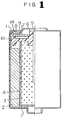
- Fig. 1 is a view of a cylindrical alkaline battery comprising a first embodiment of the present invention (partial sectional view of the left half);
- Fig. 2 is an enlarged sectional view showing the sealed portion of the battery in Fig. 1;
- Fig. 3 is a partial sectional view of a cylindrical alkaline battery for another embodiment of the present invention;
- Fig. 4 is a partial sectional view of a cylindrical alkaline battery for a further embodiment of the present invention;
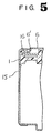
- Figs. 5 is a partial sectional view of a cylindrical alkaline battery for a still further embodiment of the present invention;
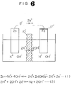
- Fig. 6 is a drawing showing schematically electrochemical reaction for the fourth embodiment of the present invention;
- Fig. 7 is an enlarged sectional view showing the sealed portion of a cylindrical alkaline battery for a fifth embodiment of the present invention; and
- Fig. 8 is a drawing showing schematically electrochemical reaction for the fifth embodiment of the present invention.
- Fig. 1 is a metallic battery case functioning as a positive electrode terminal, which contains a positive electrode mix 2 composed mainly of MnO2 and moulded into a cylindrical shape, a bag-shaped separator 4 and a gel-like zinc negative electrode 3.
- Symbol 5 is a negative electrode collector.
- the bottom plate 6 acting as a negative electrode terminal is spot-welded to the end of the negative electrode collector 5 and has an exhaust port 7. This bottom plate 6 is held by caulking the opening 11 of the battery case inwardly and tightening the bottom plate 6 together with a metallic washer 8 provided between the bottom plate 6 and the nylon gasket 10 against a nylon gasket 10.
- a metallic washer 8 provided between the bottom plate 6 and the nylon gasket 10 against a nylon gasket 10.
- the opening end 11 and the opening outer surface of the battery case 1 are covered with a ring-shaped electric insulating film 14.
- the electric insulating film 14 may cover the entire outer surface of the battery case 1 from the caulked opening portion to the bottom end of the cylinder.
- a shrink label or shrink tube 15 is applied as a cover.
- the electric insulating film 14 can be formed by, after caulking the opening 11 of the battery case 1 and sealing the opening 11 with the gasket, applying a synthetic resin coating (e.g. phenolic resin coating, epoxy resin coating) to the outer surface of the caulked portion of the battery case 1 and then drying the coating.
- a synthetic resin coating e.g. phenolic resin coating, epoxy resin coating
- the battery of the present invention wherein an electric insulating film 14 is formed on at least the opening end and the opening outer surface of the positive electrode case and then a heat-shrinkable member is applied as the cover, not only solves problems of conventional alkaline batteries having only a resin film cover but also can prevent an exterior short circuit and provide the increased reliability. Therefore, the battery has a very high value.
- an electric insulating film by applying and curing, in place of a synthetic resin coating requiring a long drying time; an ultraviolet-curable resin composed mainly of, for example, an epoxy acrylate or an aromatic monoacrylate curable in a short time by ultraviolet irradiation. That is, a synthetic resin coating requires about 30 minutes for drying and formation of film, however, an ultraviolet-curable resin can provide a cured film by ultraviolet irradiation of only about 3 seconds and can give substantially increased work efficiency.
- an insulating ring 16 may be fixed onto the outer surface of the cover film 15 at the caulked portion of the positive electrode case 1 after the cover film 15 consisting of a shrink label or shrink tube has been applied on the entire outer surface of the sealed positive electrode case 1, as shown in Fig. 4.
- the presence of this insulating ring 16 can prevent the peeling or damage of the cover label or cover tube at the battery bottom, can maintain good electric insulation between the positive electrode case 1 and the metallic bottom plate 6 being the negative electrode terminal, and can sufficiently prevent exterior short circuit.
- the insulating ring 16 can be fixed, for example, by ultrasonic-bonding of an insulating ring 16 to the cover film 15 at the caulked portion of the positive electrode case 1 or by adhering an insulating ring 16 to the cover film 15 at the caulked portion of the positive electrode case 1 with an adhesive of solution type, aqueous dispersion type, reactive type or the like.
- the insulating ring 16 can be fixed according to a method as shown in Fig. 5 wherein a lobe 6' is provided at the outer surface of the bottom plate 6 being the negative electrode terminal and an insulating ring 16 is fixed below the lobe 6'.
- the battery of the present invention wherein an insulating ring is fixed onto the outer surface of the cover film at the caulked opening portion of the positive electrode case, solves the problem of conventional alkaline batteries having only a resin film cover, prevents exterior short circuit and provides increased reliability.
- Fig. 2 is an enlarged sectional view of the sealed portion of a cylindrical alkaline battery of the present invention.
- 17 is an insulating film applied onto the upper surface of the metallic washer 8 and characterises the present embodiment.
- the constituting elements of this battery excluding the insulating film 17 are same as those of the battery of Fig. 1.
- This insulating film 17 insulates electrically the metallic washer 8 from the bottom plate 6 being the negative electrode terminal.
- the application of the insulating film 17 onto the upper surface of the metallic washer 8 can prevent leakage even when the battery has been stored under highly humid conditions.
- Fig. 7 is an enlarged sectional view of the sealed opening portion of a cylindrical alkaline battery (drawn in the form of an uncovered battery) as the fifth embodiment of the present invention.
- 17 is an insulating film applied onto the lower surface and both ends of the metallic washer 8.
- the constituting elements of this battery excluding the insulating film 17 are same as those of the battery of Fig. 1.
- This film 17 cuts off the ionic conduction between the metallic washer 8 and the hydrous nylon gasket 10.
- Fig. 8 which illustrates a schematic case of the electrochemical reaction.
- 17' is an insulating film corresponding to the insulating film 17 of Fig. 7.
- Fig. 8 is an insulating film corresponding to the insulating film 17 of Fig. 7.
- Table 1 shows the results of leakage resistance when alkaline batteries meeting the IEC standard, LR 6 were stored under conditions of 60 o C and 90% relative humidity.
- the alkaline batteries of the fourth and fifth embodiments and the above-mentioned other embodiment of the present invention show remarkably improved leakage resistance.
Landscapes
- Chemical & Material Sciences (AREA)
- Chemical Kinetics & Catalysis (AREA)
- Electrochemistry (AREA)
- General Chemical & Material Sciences (AREA)
- Engineering & Computer Science (AREA)
- Manufacturing & Machinery (AREA)
- General Engineering & Computer Science (AREA)
- Mechanical Engineering (AREA)
- Physics & Mathematics (AREA)
- Thermal Sciences (AREA)
- Sealing Battery Cases Or Jackets (AREA)
Abstract
Description
- The present invention relates to a cylindrical alkaline battery comprising an uncovered battery body and a heat-shrinkable cover member such as a shrink label, a shrink tube or the like. More particularly, the present invention relates to a cylindrical alkaline battery comprising an uncovered battery body and a heat-shrinkable cover member, wherein short circuits caused by the contact between the positive electrode case and a bottom plate being the negative electrode terminal via a third electroconductive material are prevented, and which further possesses improved leakage resistance.
- In alkaline batteries, in order that the cover can have a simplified structure and thereby allow the metallic battery case accommodating an electricity-generating element to have a larger diameter, the metallic battery case accommodating an electricity-generating element and functioning as the positive electrode terminal has been covered and insulated with a shrink label or tube having metal deposition on one side. This arrangement, when compared with a metallic battery case covered with a metallic can, enables the accommodation of a larger amount of an electricity-generating element inside the battery case, and provides a larger battery capacity. In the label-covered batteries, the shrink label is adhered to the outer surface of the battery case using an adhesive, and the projected portions of the label at the top and bottom ends of the case are subjected to shrinkage. However, in some cases, the label may peel at its ends due to deterioration of the adhesive or friction applied during transfer or storage of the battery.
- For the tube-covered batteries wherein a battery case is inserted into a cylindrical shrink tube and the tube is heat-shrunk, there occurs at times during high temperature storage of the battery further heat shrinkage of the upper and lower ends of the shrunk tube leading to an increase in the extent of exposure of the top and bottom ends of the battery case and reduced strength of the cover. In these label- or tube-covered batteries, besides the above-mentioned peeling or abnormal shrinkage of the label or tube in the vicinity of the opening of the battery case, there tends to occur damage (e.g. peeling, cutting) to the label or tube by contacting with terminals of an electric apparatus using such a battery, at the time of insertion or removal of the battery into or from the apparatus. Therefore, there may be a tendency for exterior short circuits to occur between the caulked portion of the positive electrode case and the bottom plate being the negative electrode terminal which are both metallic and are located adjacent each other, when the battery is inserted into an electric apparatus or is placed on a metal plate with the positive electrode terminal directed upward, whereby rupturing of the battery or leakage is induced.
- Generally, in alkaline batteries covered with a heat-shrinkable member, it is necessary to provide an exhaust port on the bottom plate being the negative electrode terminal to enable the discharge of gas generated inside the battery with a tiny explosion-proof mechanism having a thin nylon gasket breakable under increase in the internal pressure of the battery. In such alkaline batteries, when the sealing strength of the sealing gasket is weak, leakage of the electrolytic solution tends to occur along the sealing gasket during storage of the battery, because the caustic potash electrolytic solution used in alkaline batteries has a high creeping property. Hence, in order to obtain an alkaline battery of increased leakage resistance, there is generally adopted such a sealing structure as providing a metallic washer between the gasket and the bottom plate being the negative electrode terminal to increase sealing strength for the sealing gasket.
- In an alkaline battery having such a sealing structure, however, potassium ion (K⁺) permeates the nylon gasket according to the mechanism described later when the battery is stored under highly humid conditions (e.g. 90% relative humidity and 60oC); therefore, severe leakage occurs when the battery is stored under highly humid conditions over a long period of time such as one month or longer.
- The reason for this is that when the above alkaline battery is stored under highly humid conditions, moisture in the atmosphere penetrates into the battery through the exhaust port on the bottom plate being the negative electrode terminal, reaches the space between the metallic washer and the nylon gasket, and causes dew condensation and as the result, the interface between the metallic washer and the nylon gasket is moistened by water and the gasket turns to a hydrous nylon, thereby forming an electrochemical reaction route.
- The reaction mechanism is as follows. On the surface of the zinc present in the aqueous caustic potash solution, there occurs a zinc dissolution reaction represented by the following formula (1).

- On the water-moistened surface of the iron constituting the metallic washer which is electrically connected to the zinc via the bottom plate being the negative electrode terminal, there occurs a hydrogen formation reaction represented by the following formula (2).

- Concurrently with the above reactions, the hydrous nylon acts as a diaphragm through which K⁺ migrates, and water present on the iron surface is gradually converted into an aqueous caustic potash solution (K⁺ + OH⁻), to finally turn the solution highly alkaline. The thus formed alkaline solution leaks out through the exhaust port on the bottom plate being the negative electrode terminal, thus causing severe leakage.
- As mentioned above, conventional alkaline batteries covered with a heat-shrinkable member have various problems to be solved with respect to the reliability of cover, safety of battery and leakage.
- It is an object of the present invention to provide means for cutting off the above-mentioned electrochemical reaction route resulting in the increased leakage resistance of cylindrical alkaline batteries.
- Means to achieve this object in the construction of a cylindrical alkaline battery which has a washer between the nylon gasket sealing the opening of the positive electrode case and the bottom plate being the negative electrode terminal, comprises (a) employing the bottom plate being the negative electrode terminal treated to be electrically insulating on at least one side which contacts with the metallic washer, or (b) employing the metallic washer treated to be electrically insulating on at least one side contacting with the bottom plate being the negative electrode terminal, or (c) employing the metallic washer treated to be electrically insulating on at least one side contacting with the nylon gasket, or (d) employing an electric insulating washer, or (e) employing the nylon washer treated to be electrically insulating on at least one side contacting with the metallic washer, or (f) installing an insulator between the bottom plate being the negative electrode terminal and the metallic washer, or (g) installing an insulator between the metallic washer and the nylon gasket.
- Fig. 1 is a view of a cylindrical alkaline battery comprising a first embodiment of the present invention (partial sectional view of the left half); Fig. 2 is an enlarged sectional view showing the sealed portion of the battery in Fig. 1; Fig. 3 is a partial sectional view of a cylindrical alkaline battery for another embodiment of the present invention; Fig. 4 is a partial sectional view of a cylindrical alkaline battery for a further embodiment of the present invention; Figs. 5 is a partial sectional view of a cylindrical alkaline battery for a still further embodiment of the present invention; Fig. 6 is a drawing showing schematically electrochemical reaction for the fourth embodiment of the present invention; Fig. 7 is an enlarged sectional view showing the sealed portion of a cylindrical alkaline battery for a fifth embodiment of the present invention; and Fig. 8 is a drawing showing schematically electrochemical reaction for the fifth embodiment of the present invention.
- The embodiments of the present invention are explained in detail referring to the accompanying drawings. In Fig. 1, 1 is a metallic battery case functioning as a positive electrode terminal, which contains a
positive electrode mix 2 composed mainly of MnO₂ and moulded into a cylindrical shape, a bag-shaped separator 4 and a gel-like zincnegative electrode 3.Symbol 5 is a negative electrode collector. Thebottom plate 6 acting as a negative electrode terminal is spot-welded to the end of thenegative electrode collector 5 and has anexhaust port 7. Thisbottom plate 6 is held by caulking the opening 11 of the battery case inwardly and tightening thebottom plate 6 together with a metallic washer 8 provided between thebottom plate 6 and the nylon gasket 10 against anylon gasket 10. As shown in Fig. 2, at least the opening end 11 and the opening outer surface of thebattery case 1 are covered with a ring-shapedelectric insulating film 14. As shown in Fig. 3, the electricinsulating film 14 may cover the entire outer surface of thebattery case 1 from the caulked opening portion to the bottom end of the cylinder. Thereon, a shrink label orshrink tube 15 is applied as a cover. In such a structure, since the opening of the case is covered with the electricinsulating film 14, good electric insulation can be maintained between the positive electrode case and the metallic bottom plate being the negative electrode terminal even when a portion of the label or tube covering the opening of the case undergoes peeling or damage due to deterioration during storage or friction, and this can prevent the rupture of the positive electrode case or the leakage of electrolytic solution which is induced by an exterior short circuit due to contact of a third electroconductive material with both of the positive electrode case and the bottom plate being the negative electrode terminal. Incidentally, theelectric insulating film 14 can be formed by, after caulking the opening 11 of thebattery case 1 and sealing the opening 11 with the gasket, applying a synthetic resin coating (e.g. phenolic resin coating, epoxy resin coating) to the outer surface of the caulked portion of thebattery case 1 and then drying the coating. - Thus, the battery of the present invention, wherein an electric
insulating film 14 is formed on at least the opening end and the opening outer surface of the positive electrode case and then a heat-shrinkable member is applied as the cover, not only solves problems of conventional alkaline batteries having only a resin film cover but also can prevent an exterior short circuit and provide the increased reliability. Therefore, the battery has a very high value. - In the present invention, it is possible to form an electric insulating film by applying and curing, in place of a synthetic resin coating requiring a long drying time; an ultraviolet-curable resin composed mainly of, for example, an epoxy acrylate or an aromatic monoacrylate curable in a short time by ultraviolet irradiation. That is, a synthetic resin coating requires about 30 minutes for drying and formation of film, however, an ultraviolet-curable resin can provide a cured film by ultraviolet irradiation of only about 3 seconds and can give substantially increased work efficiency.
- In the present invention, as a means to prevent an exterior short circuit, an
insulating ring 16 may be fixed onto the outer surface of thecover film 15 at the caulked portion of thepositive electrode case 1 after thecover film 15 consisting of a shrink label or shrink tube has been applied on the entire outer surface of the sealedpositive electrode case 1, as shown in Fig. 4. The presence of this insulatingring 16 can prevent the peeling or damage of the cover label or cover tube at the battery bottom, can maintain good electric insulation between thepositive electrode case 1 and themetallic bottom plate 6 being the negative electrode terminal, and can sufficiently prevent exterior short circuit. Incidentally, theinsulating ring 16 can be fixed, for example, by ultrasonic-bonding of aninsulating ring 16 to thecover film 15 at the caulked portion of thepositive electrode case 1 or by adhering aninsulating ring 16 to thecover film 15 at the caulked portion of thepositive electrode case 1 with an adhesive of solution type, aqueous dispersion type, reactive type or the like. - Alternatively, the
insulating ring 16 can be fixed according to a method as shown in Fig. 5 wherein a lobe 6' is provided at the outer surface of thebottom plate 6 being the negative electrode terminal and aninsulating ring 16 is fixed below the lobe 6'. - Thus, the battery of the present invention wherein an insulating ring is fixed onto the outer surface of the cover film at the caulked opening portion of the positive electrode case, solves the problem of conventional alkaline batteries having only a resin film cover, prevents exterior short circuit and provides increased reliability.
- Next, the fourth embodiment of the present invention for preventing the leakage phenomenon caused by the above-mentioned electrochemical reaction is illustrated referring to the drawings. Fig. 2 is an enlarged sectional view of the sealed portion of a cylindrical alkaline battery of the present invention. In Fig. 2, 17 is an insulating film applied onto the upper surface of the metallic washer 8 and characterises the present embodiment. The constituting elements of this battery excluding the
insulating film 17 are same as those of the battery of Fig. 1. Thisinsulating film 17 insulates electrically the metallic washer 8 from thebottom plate 6 being the negative electrode terminal. - In the present embodiment, since the
bottom plate 6 being the negative electrode terminal and the metallic washer 8 are electrically insulated from each other by theinsulating film 17 applied onto the metallic washer 8, no leakage occurs, for example, even moisture reaches thespace 13 between thenylon gasket 10 and the metallic washer 8, and the interface between them is wetted by water, when the battery is stored under highly humid condition. The mechanism for this electrochemical reaction is explained in Fig. 6 which illustrates a schematic case of the electrochemical reaction. In Fig. 6, 17' is an insulating film corresponding to theinsulating film 17 of Fig. 2. In Fig. 6, since Zn and Fe are insulated electrically, any of the reactions of the formulae (1) and (2) do not proceed; there occurs no movement of K⁺ into the water which wets the iron washer; accordingly, the water does not become alkaline. Thus, according to the fourth embodiment of the present invention, the application of theinsulating film 17 onto the upper surface of the metallic washer 8 can prevent leakage even when the battery has been stored under highly humid conditions. - Fig. 7 is an enlarged sectional view of the sealed opening portion of a cylindrical alkaline battery (drawn in the form of an uncovered battery) as the fifth embodiment of the present invention. In Fig. 7, 17 is an insulating film applied onto the lower surface and both ends of the metallic washer 8. The constituting elements of this battery excluding the
insulating film 17 are same as those of the battery of Fig. 1. Thisfilm 17 cuts off the ionic conduction between the metallic washer 8 and thehydrous nylon gasket 10. - In the present embodiment, since the ionic conduction between the metallic washer 8 and the
hydrous nylon gasket 10 is cut off by theinsulating film 17 applied onto the lower surface and both ends of the metallic washer 8, no leakage occurs for example, even when the battery is stored under highly humid conditions and moisture reaches thespace 13 between thenylon gasket 10 and the metallic washer 8. The mechanism for this electrochemical reaction is explained in Fig. 8 which illustrates a schematic case of the electrochemical reaction. In Fig. 8, 17' is an insulating film corresponding to theinsulating film 17 of Fig. 7. In Fig. 8, since any portion of Fe is not in direct contact with water, the H₂ formation reaction represented by the formula (2) does not take place on the Fe surface, and accordingly, the reaction of the formula (1) does not take place, either; there occurs no movement of K⁺ into the water which wets the washer; consequently, the water does not become alkaline. Thus, according to the fifth embodiment of the present invention illustrated in Fig. 7 the application of theinsulating film 17 onto the lower surface and two ends of the metallic washer 8 can prevent leakage even when the battery has been stored under highly humid conditions. - As is understood from the above embodiments of the present invention, in a cylindrical alkaline battery wherein a washer 8 is provided between the
nylon gasket 10 and thebottom plate 6 being the negative electrode terminal each acting as a sealant for the opening of thepositive electrode case 1, leakage occurring when the battery has been stored under highly humid conditions can be prevented by insulating thebottom plate 6 being the negative electrode terminal and the metallic washer 8 by (1) applying an insulating film onto the metallic washer 8, (2) placing a ring-shaped insulating washer between them, or (3) using an electric insulation as the metallic washer 8, or by electrically or ion-conductively insulating the metallic washer 8 and the nylon gasket 10 by placing a chlorosulfonated polyethylene film between them. As a result, excellent cylindrical alkaline batteries can be provided. Table 1 shows the results of leakage resistance when alkaline batteries meeting the IEC standard,LR 6 were stored under conditions of 60oC and 90% relative humidity. As is clear from Table 1, the alkaline batteries of the fourth and fifth embodiments and the above-mentioned other embodiment of the present invention, as compared with a conventional alkaline battery of same size, show remarkably improved leakage resistance.
Claims (8)
- A cylindrical alkaline battery comprising
a positive electrode case of a cylindrical form having an opening at one end and accommodating an electricity-generating element comprising a positive electrode, a negative electrode, a separator and an alkaline electrolytic solution,
a gasket made of an electric insulating synthetic resin and installed at the opening of the positive electrode case,
a bottom plate being the negative electrode terminal electrically connected to the negative electrode in the electricity-generating element and installed on the gasket,
a reinforcing washer provided between the bottom plate being the negative electrode terminal and the gasket, and
a heat-shrinkable resin member covering the outer surface of the positive electrode case, wherein the opening of the positive electrode case is sealed by bending the opening end inwardly and thereby tightening the bottom plate being the negative electrode terminal and the washer against the gasket. - A cylindrical alkaline battery comprising
a positive electrode case of a cylindrical form having an opening at one end and accommodating an electricity-generating element composed of a positive electrode, a negative electrode, a separator and an alkaline electrolytic solution,
a gasket made of nylon and installed at the opening of the positive electrode case,
a bottom plate being the negative electrode terminal electrically connected to the negative electrode in the electricity-generating element and installed on the gasket,
a reinforcing metallic washer provided between the bottom plate being the negative electrode terminal and the gasket, and
a heat-shrinkable resin member covering the outer surface of the positive electrode case, wherein the opening of the positive electrode case is sealed by bending the opening end inwardly and thereby tightening the bottom plate being the negative electrode terminal and the washer against the gasket, and wherein electric insulation is established between the bottom plate being the negative electrode terminal and the washer or, electric insulation and ion-impermeability are established between the gasket and the washer. - The cylindrical alkaline battery according to claim 2, wherein the reinforcing washer is a metallic washer covered with insulation at least on its upper surface.
- The cylindrical alkaline battery according to claim 2, wherein the reinforcing washer is covered with an ion-impermeable insulation on its lower surface and both side ends.
- The cylindrical alkaline battery according to claim 1, wherein the reinforcing washer is an electric insulator.
- The cylindrical alkaline battery according to claim 2, wherein the electric insulation between the bottom plate being the negative electrode terminal and the metallic washer is provided by a ring-shaped insulator.
- The cylindrical alkaline battery according to claim 2, wherein the electric insulation between the insulating gasket and the metallic washer is provided by a coating film of chlorosulfonated polyethylene.
- A cylindrical alkaline battery comprising
a positive electrode case of a cylindrical form having an opening at one end and accommodating an electricity-generating element comprising a positive electrode, a negative electrode, a separator and an alkaline electrolytic solution,
a gasket made of nylon and installed at the opening of the positive electrode case,
a bottom plate being the negative electrode terminal electrically connected to the negative electrode in the electricity-generating element and installed on the gasket,
a reinforcing metallic washer provided between the bottom plate being the negative electrode terminal and the gasket, and
a heat-shrinkable resin member covering the outer surface of the positive electrode case, wherein the opening of the positive electrode case is sealed by bending the opening end inwardly and thereby tightening the bottom plate being the negative electrode terminal and the washer against the gasket, and wherein electric insulation is established between the bottom plate being the negative electrode terminal and the washer or, electric insulation and ion-impermeability are established between the gasket and the washer, and an electrically insulating coating is formed on the opening end of the positive electrode case and the outer surface of a bent portion of the opening end.
Applications Claiming Priority (7)
| Application Number | Priority Date | Filing Date | Title |
|---|---|---|---|
| JP215651/87 | 1987-08-28 | ||
| JP62215651A JPS6459756A (en) | 1987-08-28 | 1987-08-28 | Alkaline dry battery |
| JP331994/87 | 1987-12-28 | ||
| JP62331994A JPH01175163A (en) | 1987-12-28 | 1987-12-28 | alkaline battery |
| JP63113909A JP2769158B2 (en) | 1988-05-11 | 1988-05-11 | Alkaline batteries |
| JP113909/88 | 1988-05-11 | ||
| EP88307958A EP0309101B1 (en) | 1987-08-28 | 1988-08-26 | Cylindrical alkaline batteries |
Related Parent Applications (1)
| Application Number | Title | Priority Date | Filing Date |
|---|---|---|---|
| EP88307958.4 Division | 1988-08-26 |
Publications (3)
| Publication Number | Publication Date |
|---|---|
| EP0466213A2 true EP0466213A2 (en) | 1992-01-15 |
| EP0466213A3 EP0466213A3 (en) | 1992-03-04 |
| EP0466213B1 EP0466213B1 (en) | 1996-01-10 |
Family
ID=27312616
Family Applications (2)
| Application Number | Title | Priority Date | Filing Date |
|---|---|---|---|
| EP88307958A Expired - Lifetime EP0309101B1 (en) | 1987-08-28 | 1988-08-26 | Cylindrical alkaline batteries |
| EP91116087A Expired - Lifetime EP0466213B1 (en) | 1987-08-28 | 1988-08-26 | Cylindrical alkaline batteries |
Family Applications Before (1)
| Application Number | Title | Priority Date | Filing Date |
|---|---|---|---|
| EP88307958A Expired - Lifetime EP0309101B1 (en) | 1987-08-28 | 1988-08-26 | Cylindrical alkaline batteries |
Country Status (6)
| Country | Link |
|---|---|
| US (1) | US4869978A (en) |
| EP (2) | EP0309101B1 (en) |
| KR (1) | KR920004316B1 (en) |
| AU (1) | AU594249B2 (en) |
| CA (1) | CA1305753C (en) |
| DE (2) | DE3854899T2 (en) |
Families Citing this family (17)
| Publication number | Priority date | Publication date | Assignee | Title |
|---|---|---|---|---|
| US5051323A (en) * | 1990-04-13 | 1991-09-24 | Eveready Battery Company, Inc. | Rollback inner cover |
| JP2543325Y2 (en) * | 1991-01-14 | 1997-08-06 | ソニー株式会社 | Battery |
| US5173371A (en) * | 1991-03-11 | 1992-12-22 | Eveready Battery Company, Inc. | Battery to prevent cell reversal |
| FR2680132A1 (en) * | 1991-08-05 | 1993-02-12 | Rotanotice Sa | Method for obtaining a protective and decorative label around the cylindrical body of an electric battery |
| US5324332A (en) * | 1992-10-30 | 1994-06-28 | Rayovac Corporation | Alkaline manganese dioxide cells |
| DE19643011A1 (en) * | 1996-10-18 | 1998-04-23 | Varta Batterie | Directly overprinted galvanic element |
| JP3612931B2 (en) * | 1996-10-31 | 2005-01-26 | 松下電器産業株式会社 | Cylindrical alkaline battery |
| US5985479A (en) * | 1997-11-14 | 1999-11-16 | Eveready Battery Company, Inc. | Electrochemical cell having current path interrupter |
| TWI275194B (en) * | 2004-10-08 | 2007-03-01 | Lg Chemical Ltd | Secondary battery having an improved safety |
| US8053106B1 (en) * | 2005-12-01 | 2011-11-08 | Quallion Llc | Battery with improved insulator |
| KR100795682B1 (en) * | 2006-02-27 | 2008-01-21 | 삼성에스디아이 주식회사 | Secondary Battery and Manufacturing Method Thereof |
| US20090029238A1 (en) * | 2007-07-25 | 2009-01-29 | Schubert Mark A | Electrochemical cell having polymeric moisture barrier |
| JP2010003681A (en) * | 2008-05-19 | 2010-01-07 | Panasonic Corp | Electricity storage device |
| AT508742B1 (en) * | 2009-09-10 | 2011-07-15 | Norman Neuhold | INSERT FOR AN ACCUMULATOR PART |
| CN103531729B (en) * | 2013-10-31 | 2015-10-14 | 无锡市金杨新型电源有限公司 | Battery case production notching mechanism |
| AU2021273919A1 (en) | 2020-05-22 | 2022-10-06 | Duracell U.S. Operations, Inc. | Seal assembly for a battery cell |
| KR102868036B1 (en) * | 2020-06-25 | 2025-10-01 | 삼성에스디아이 주식회사 | Rechargeable battery |
Family Cites Families (9)
| Publication number | Priority date | Publication date | Assignee | Title |
|---|---|---|---|---|
| US3694267A (en) * | 1970-11-23 | 1972-09-26 | Mallory & Co Inc P R | Leakproof closure seal for battery |
| FR2123618A5 (en) * | 1971-01-25 | 1972-09-15 | Accumulateurs Fixes | |
| FR2148841A5 (en) * | 1971-08-05 | 1973-03-23 | Sev Marchal | |
| US3897270A (en) * | 1973-01-30 | 1975-07-29 | Power Conversion Inc | Battery construction with improved terminal attaching structure |
| DE2321842C3 (en) * | 1973-04-30 | 1980-09-11 | Fuji Electrochemical Co. Ltd., Tokio | Electrochemical cell |
| JPS56138860A (en) * | 1980-04-01 | 1981-10-29 | Hitachi Maxell Ltd | Cylindrical alkaline battery |
| US4567118A (en) * | 1983-07-11 | 1986-01-28 | Duracell Inc. | Cell vent |
| US4537841A (en) * | 1983-11-04 | 1985-08-27 | Duracell Inc. | Metal-supported seals for galvanic cells |
| US4606983A (en) * | 1985-02-25 | 1986-08-19 | Duracell Inc. | Anchored terminal conductor |
-
1988
- 1988-08-12 KR KR1019880010294A patent/KR920004316B1/en not_active Expired - Lifetime
- 1988-08-22 US US07/234,603 patent/US4869978A/en not_active Expired - Lifetime
- 1988-08-23 AU AU21454/88A patent/AU594249B2/en not_active Expired
- 1988-08-25 CA CA000575720A patent/CA1305753C/en not_active Expired - Lifetime
- 1988-08-26 EP EP88307958A patent/EP0309101B1/en not_active Expired - Lifetime
- 1988-08-26 DE DE3854899T patent/DE3854899T2/en not_active Expired - Lifetime
- 1988-08-26 EP EP91116087A patent/EP0466213B1/en not_active Expired - Lifetime
- 1988-08-26 DE DE8888307958T patent/DE3878617T2/en not_active Expired - Lifetime
Also Published As
| Publication number | Publication date |
|---|---|
| EP0309101A2 (en) | 1989-03-29 |
| DE3878617D1 (en) | 1993-04-01 |
| EP0466213A3 (en) | 1992-03-04 |
| KR890004460A (en) | 1989-04-22 |
| EP0466213B1 (en) | 1996-01-10 |
| EP0309101B1 (en) | 1993-02-24 |
| CA1305753C (en) | 1992-07-28 |
| DE3878617T2 (en) | 1993-06-09 |
| AU2145488A (en) | 1989-05-25 |
| DE3854899D1 (en) | 1996-02-22 |
| DE3854899T2 (en) | 1996-09-12 |
| EP0309101A3 (en) | 1989-11-15 |
| US4869978A (en) | 1989-09-26 |
| KR920004316B1 (en) | 1992-06-01 |
| AU594249B2 (en) | 1990-03-01 |
Similar Documents
| Publication | Publication Date | Title |
|---|---|---|
| EP0466213A2 (en) | Cylindrical alkaline batteries | |
| FI65688C (en) | CONTACT CONTROL FOR BATTERIES I ETT GALVANISKT BATTERI | |
| EP0164963A2 (en) | Insulating seal for electrochemical cells | |
| US5079108A (en) | Dry cell seal closure | |
| US3922178A (en) | Alkaline battery seal and protective coating comprising a fatty acidamide | |
| US3081367A (en) | Electrode assembly for sealed rechargeable alkaline battery cells | |
| US3042734A (en) | Alkaline cell closure | |
| CN1301404A (en) | End cap assembly for an alkaline cell | |
| KR101006883B1 (en) | Battery containing electrolyte suction washer | |
| US3644145A (en) | Incorporation of valve metals into current-producing cell constructions | |
| JP3612931B2 (en) | Cylindrical alkaline battery | |
| EP0081339A2 (en) | Sealing of electrochemical cells | |
| US3694267A (en) | Leakproof closure seal for battery | |
| US2636063A (en) | Electrical battery | |
| JP3077215B2 (en) | Battery | |
| US5168017A (en) | Metal oxide-hydrogen battery having rectangular modules in a cylindrical pressure vessel | |
| EP0089496A1 (en) | Galvanic cell construction and method for its assembly | |
| JP2001332226A (en) | Alkaline batteries | |
| CN119856335A (en) | Battery cell | |
| US5789102A (en) | Alkaline cell and separator therefor | |
| KR100551395B1 (en) | Pouch type lithium secondary battery manufacturing method | |
| JP3240911B2 (en) | Spiral lithium battery, method of manufacturing the same, and liquid injection device | |
| CN222785289U (en) | First pole piece, winding cell and battery | |
| JPH02139849A (en) | Cylindrical alkaline cell | |
| KR100319107B1 (en) | Sealed battery and method for making the same |
Legal Events
| Date | Code | Title | Description |
|---|---|---|---|
| PUAI | Public reference made under article 153(3) epc to a published international application that has entered the european phase |
Free format text: ORIGINAL CODE: 0009012 |
|
| PUAL | Search report despatched |
Free format text: ORIGINAL CODE: 0009013 |
|
| 17P | Request for examination filed |
Effective date: 19910921 |
|
| AC | Divisional application: reference to earlier application |
Ref document number: 309101 Country of ref document: EP |
|
| AK | Designated contracting states |
Kind code of ref document: A2 Designated state(s): BE CH DE FR GB IT LI NL |
|
| AK | Designated contracting states |
Kind code of ref document: A3 Designated state(s): BE CH DE FR GB IT LI NL |
|
| RIN1 | Information on inventor provided before grant (corrected) |
Inventor name: IWAKI, HIROFUMI Inventor name: KUBO, ISAO Inventor name: KANEKO, TOSHIKAZU Inventor name: KAJIKAWA, YOJI Inventor name: MIYOSHI, JUN Inventor name: ASAOKA, JUNICHI |
|
| 17Q | First examination report despatched |
Effective date: 19930923 |
|
| ITF | It: translation for a ep patent filed | ||
| GRAA | (expected) grant |
Free format text: ORIGINAL CODE: 0009210 |
|
| AC | Divisional application: reference to earlier application |
Ref document number: 309101 Country of ref document: EP |
|
| AK | Designated contracting states |
Kind code of ref document: B1 Designated state(s): BE CH DE FR GB IT LI NL |
|
| REF | Corresponds to: |
Ref document number: 3854899 Country of ref document: DE Date of ref document: 19960222 |
|
| ET | Fr: translation filed | ||
| REG | Reference to a national code |
Ref country code: CH Ref legal event code: NV Representative=s name: A. BRAUN, BRAUN, HERITIER, ESCHMANN AG PATENTANWAE |
|
| PLBE | No opposition filed within time limit |
Free format text: ORIGINAL CODE: 0009261 |
|
| STAA | Information on the status of an ep patent application or granted ep patent |
Free format text: STATUS: NO OPPOSITION FILED WITHIN TIME LIMIT |
|
| 26N | No opposition filed | ||
| REG | Reference to a national code |
Ref country code: GB Ref legal event code: IF02 |
|
| PGFP | Annual fee paid to national office [announced via postgrant information from national office to epo] |
Ref country code: NL Payment date: 20060815 Year of fee payment: 19 |
|
| PGFP | Annual fee paid to national office [announced via postgrant information from national office to epo] |
Ref country code: DE Payment date: 20070823 Year of fee payment: 20 |
|
| PGFP | Annual fee paid to national office [announced via postgrant information from national office to epo] |
Ref country code: CH Payment date: 20070830 Year of fee payment: 20 |
|
| PGFP | Annual fee paid to national office [announced via postgrant information from national office to epo] |
Ref country code: GB Payment date: 20070822 Year of fee payment: 20 |
|
| PGFP | Annual fee paid to national office [announced via postgrant information from national office to epo] |
Ref country code: IT Payment date: 20070828 Year of fee payment: 20 |
|
| PGFP | Annual fee paid to national office [announced via postgrant information from national office to epo] |
Ref country code: BE Payment date: 20071018 Year of fee payment: 20 |
|
| PG25 | Lapsed in a contracting state [announced via postgrant information from national office to epo] |
Ref country code: NL Free format text: LAPSE BECAUSE OF NON-PAYMENT OF DUE FEES Effective date: 20080301 |
|
| PGFP | Annual fee paid to national office [announced via postgrant information from national office to epo] |
Ref country code: FR Payment date: 20070808 Year of fee payment: 20 |
|
| NLV4 | Nl: lapsed or anulled due to non-payment of the annual fee |
Effective date: 20080301 |
|
| REG | Reference to a national code |
Ref country code: CH Ref legal event code: PFA Owner name: MATSUSHITA ELECTRIC INDUSTRIAL CO., LTD. Free format text: MATSUSHITA ELECTRIC INDUSTRIAL CO., LTD.#1006, OHAZA KADOMA#KADOMA-SHI, OSAKA-FU, 571 (JP) -TRANSFER TO- MATSUSHITA ELECTRIC INDUSTRIAL CO., LTD.#1006, OHAZA KADOMA#KADOMA-SHI, OSAKA-FU, 571 (JP) |
|
| BE20 | Be: patent expired |
Owner name: *MATSUSHITA ELECTRIC INDUSTRIAL CO. LTD Effective date: 20080826 |
|
| REG | Reference to a national code |
Ref country code: CH Ref legal event code: PL |
|
| REG | Reference to a national code |
Ref country code: GB Ref legal event code: PE20 Expiry date: 20080825 |
|
| PG25 | Lapsed in a contracting state [announced via postgrant information from national office to epo] |
Ref country code: GB Free format text: LAPSE BECAUSE OF EXPIRATION OF PROTECTION Effective date: 20080825 |