EP0465941A2 - Plasma torch with transferred arc - Google Patents
Plasma torch with transferred arc Download PDFInfo
- Publication number
- EP0465941A2 EP0465941A2 EP91110640A EP91110640A EP0465941A2 EP 0465941 A2 EP0465941 A2 EP 0465941A2 EP 91110640 A EP91110640 A EP 91110640A EP 91110640 A EP91110640 A EP 91110640A EP 0465941 A2 EP0465941 A2 EP 0465941A2
- Authority
- EP
- European Patent Office
- Prior art keywords
- plasma torch
- end piece
- torch according
- jacket
- nozzle end
- Prior art date
- Legal status (The legal status is an assumption and is not a legal conclusion. Google has not performed a legal analysis and makes no representation as to the accuracy of the status listed.)
- Granted
Links
- 239000002826 coolant Substances 0.000 claims abstract description 18
- 125000006850 spacer group Chemical group 0.000 claims description 5
- 238000006073 displacement reaction Methods 0.000 claims description 3
- 239000011810 insulating material Substances 0.000 claims description 3
- 230000003071 parasitic effect Effects 0.000 abstract description 9
- 239000002245 particle Substances 0.000 abstract description 2
- 239000007789 gas Substances 0.000 description 23
- 238000009413 insulation Methods 0.000 description 8
- 239000000919 ceramic Substances 0.000 description 7
- 239000004033 plastic Substances 0.000 description 7
- 229910000831 Steel Inorganic materials 0.000 description 5
- 239000007787 solid Substances 0.000 description 5
- 239000010959 steel Substances 0.000 description 5
- 238000000576 coating method Methods 0.000 description 4
- 238000001816 cooling Methods 0.000 description 3
- 239000012774 insulation material Substances 0.000 description 3
- 238000007664 blowing Methods 0.000 description 2
- 239000011248 coating agent Substances 0.000 description 2
- 238000011161 development Methods 0.000 description 2
- 230000018109 developmental process Effects 0.000 description 2
- 230000000694 effects Effects 0.000 description 2
- 238000000265 homogenisation Methods 0.000 description 2
- 238000009434 installation Methods 0.000 description 2
- 238000000034 method Methods 0.000 description 2
- 239000000843 powder Substances 0.000 description 2
- 239000011343 solid material Substances 0.000 description 2
- 244000089486 Phragmites australis subsp australis Species 0.000 description 1
- 239000000654 additive Substances 0.000 description 1
- 230000015572 biosynthetic process Effects 0.000 description 1
- 238000010276 construction Methods 0.000 description 1
- 230000006378 damage Effects 0.000 description 1
- 230000005611 electricity Effects 0.000 description 1
- 238000001704 evaporation Methods 0.000 description 1
- 238000003780 insertion Methods 0.000 description 1
- 230000037431 insertion Effects 0.000 description 1
- 230000010354 integration Effects 0.000 description 1
- 238000002844 melting Methods 0.000 description 1
- 230000008018 melting Effects 0.000 description 1
- 229910052751 metal Inorganic materials 0.000 description 1
- 239000002184 metal Substances 0.000 description 1
- 229910044991 metal oxide Inorganic materials 0.000 description 1
- 150000004706 metal oxides Chemical class 0.000 description 1
- 230000001590 oxidative effect Effects 0.000 description 1
- 230000000149 penetrating effect Effects 0.000 description 1
- 239000002244 precipitate Substances 0.000 description 1
- 230000005855 radiation Effects 0.000 description 1
- 239000003870 refractory metal Substances 0.000 description 1
- 238000007789 sealing Methods 0.000 description 1
- 239000002893 slag Substances 0.000 description 1
- 239000000126 substance Substances 0.000 description 1
- 230000007704 transition Effects 0.000 description 1
Images

Classifications
-
- H—ELECTRICITY
- H05—ELECTRIC TECHNIQUES NOT OTHERWISE PROVIDED FOR
- H05H—PLASMA TECHNIQUE; PRODUCTION OF ACCELERATED ELECTRICALLY-CHARGED PARTICLES OR OF NEUTRONS; PRODUCTION OR ACCELERATION OF NEUTRAL MOLECULAR OR ATOMIC BEAMS
- H05H1/00—Generating plasma; Handling plasma
- H05H1/24—Generating plasma
- H05H1/26—Plasma torches
- H05H1/32—Plasma torches using an arc
- H05H1/34—Details, e.g. electrodes, nozzles
- H05H1/3431—Coaxial cylindrical electrodes
-
- H—ELECTRICITY
- H05—ELECTRIC TECHNIQUES NOT OTHERWISE PROVIDED FOR
- H05H—PLASMA TECHNIQUE; PRODUCTION OF ACCELERATED ELECTRICALLY-CHARGED PARTICLES OR OF NEUTRONS; PRODUCTION OR ACCELERATION OF NEUTRAL MOLECULAR OR ATOMIC BEAMS
- H05H1/00—Generating plasma; Handling plasma
- H05H1/24—Generating plasma
- H05H1/26—Plasma torches
- H05H1/32—Plasma torches using an arc
- H05H1/34—Details, e.g. electrodes, nozzles
-
- H—ELECTRICITY
- H05—ELECTRIC TECHNIQUES NOT OTHERWISE PROVIDED FOR
- H05H—PLASMA TECHNIQUE; PRODUCTION OF ACCELERATED ELECTRICALLY-CHARGED PARTICLES OR OF NEUTRONS; PRODUCTION OR ACCELERATION OF NEUTRAL MOLECULAR OR ATOMIC BEAMS
- H05H1/00—Generating plasma; Handling plasma
- H05H1/24—Generating plasma
- H05H1/26—Plasma torches
- H05H1/28—Cooling arrangements
Definitions
- the invention relates to a plasma torch for transmitted arc with a central electrode, a concentric nozzle end piece, wherein an annular gap for the passage of plasma gas is present between the electrode and the nozzle end piece, and a concentric burner jacket with outer, middle and inner wall, between the nozzle end piece and an annular channel is present in the burner jacket, the inner wall of which is partially formed by an insulating tube that electrically separates both parts.
- Parasitic arches not only significantly impair the stability of the arc column and thus the efficiency and economy of a plasma torch or a system operated with plasma torches, they generally even lead to the complete destruction of plasma torches.
- the insulation provided in the end face of the nozzle be laid in an end groove.
- a plasma torch has also been carried out.
- the end groove is formed on the one hand by the outer wall of a nozzle socket or end piece and on the other hand by a burner jacket, the burner jacket having on its front side a flange pointing towards the axis of the burner, which offers the insulation piece lying behind a certain heat protection.
- this burner is in an atmosphere with electrically conductive particles, e.g. B. operated metal or steel dusts, the electrically conductive dusts can precipitate on the cooled insulating piece, so that an electrical bridge from the nozzle nozzle to the burner jacket form and parasitic arcs can now flow over the outer front edge of the burner jacket.
- the invention has for its object the risk of the formation of parasitic arcs, in particular when operating with alternating current, further. H. restrict with greater success.
- the annular channel between the nozzle end piece and the burner jacket is withdrawn at least up to the level of the coolant inlet and outlet of the burner jacket and has a line connection at its rear end with a source of a pressurized gaseous medium. Due to its length, the coaxial ring channel already represents a factor that increases the operational safety and service life, because of the lack of mechanical connections on which electrically conductive vapors or dusts could be deposited, which could lead to bridges between the nozzle socket and the nozzle jacket.
- the line connection to a source of a pressurized gaseous medium is equivalent to blowing a gaseous pressure medium into the ring channel.
- Blowing the ring channel with gas represents a further step in the direction of increasing operational safety and increasing the service life.
- the mouth or outlet area of the ring channel is additionally cooled by the gas. Any electrically conductive vapors or dusts that occur are prevented from entering the ring channel. Flashback plasma arc curls are prevented and melt and slag splashes that want to penetrate into the ring channel are rejected and cooled.
- oxidation-promoting gases are shielded, which are sucked in from the environment via the plasma arc and have a strong wear-promoting effect on refractory metals that are located outside the plasma gas area.
- the plasma torch is advantageously also suitable for transporting or carrying solid substances in powder or grain form by the additional gas.
- the entire plasma arc circumference and a certain distance in the direction of the plasma arc axis can be used for melting or evaporating the solid materials in the plasma torch according to the invention.
- the homogenization of the gas flow through the ring channel can be further improved in that the line connection has a tangential component at the rear end of the ring channel.
- the line connection has a tangential component at the rear end of the ring channel.
- the at least partially tangential direction of insertion into the ring channel and the leveling that can be achieved with it is particularly important in the case of the conveyance of solids.
- the electrode and the nozzle end piece require only a low coolant throughput, it is advantageous to assign a separate cooling circuit to the burner jacket so that the required coolant throughput can be adapted to the respective degree of stress.
- the nozzle jacket is connected to the jacket tube of the burner jacket via a simple threaded connection, possibly via a connecting part. It is therefore easy to remove and thus enables the electrode and the nozzle or the nozzle end piece to be exchanged quickly for other applications, which can also be easily assembled or exchanged by means of threaded connections.
- the annular channel in its mouth region is advantageously designed to be conically converging in the direction of the arc.
- the insulating tube electrically separating the nozzle end piece and the burner jacket is adjacent to the outside of the nozzle end piece. It is also used to form the conical inner surface in the mouth region of the ring channel.
- the surfaces of the conical mouth region of the ring channel can preferably have a coating of insulation material, in particular ceramic, which makes it possible to convey electrically conductive solids through the ring channel and to feed them to the arc.
- insulation material in particular ceramic
- the insulating tube surrounding the electrode lance is further set back into the ring channel up to the line connection.
- the clear diameter of the outer edge of the ring channel at the mouth is preferably smaller than the outer diameter of the inner wall of the ring channel before the conical course begins.
- the nozzle end piece is advantageously mechanically connected to the electrode via an annular body made of insulation material and combined with it to form a structural unit.
- This annular body has passages running parallel to the main axis of the plasma torch, through which the main plasma gas can reach the annular gap between the electrode and the nozzle end piece.
- a common coolant circuit is provided for the latter.
- displacement bodies can be arranged in the ring channel.
- spacers or supporting bodies are advantageously inserted into the ring channel.
- These support bodies are shaped as aerodynamically as possible, viewed in the longitudinal axis of the burner, offset from one another and advantageously fastened to the insulating tube assigned to the electrode and the nozzle end piece.
- the support bodies can be designed as hollow and solid bodies and run axially parallel or helically and thus make a contribution to the conveyance and guidance of additives in the ring channel.
- Hollow bodies parallel to the axis can be preferred be extended as a nozzle-shaped ceramic tube beyond the end face of the nozzle end piece, for example to supply powder locally and in a directed manner to the plasma arc.
- the plasma torch essentially consists of an electrode lance and a torch jacket.
- the electrode lance again consists essentially of an electrode 10 and a nozzle nozzle or nozzle end piece 11 and the parts holding them.
- the electrode 10 has a weakly conical end surface and the nozzle nozzle 11 has a weakly conical inner surface and a more conical outer surface.
- the electrode 10 is fastened with its outer wall via a substantially sleeve-shaped connecting piece 12 to the current tube 13, a tube connected to the main voltage source, with a threaded connection or pairing in each case between the electrode 10 and the connecting piece 12 and between this and the current tube 13 consists.
- the inner wall of the electrode 10 is slidably guided on an inner tube 14 fastened in the rear end of the plasma torch. Between the flow tube 13 and the inner tube 14 there is a plastic center tube 15 for separating the partial circuits of the coolant for the electrode. In its lower area, the central tube 15 also serves to deflect the coolant flow.
- the inner wall of the nozzle end piece 11 is connected via a threaded connection to an annular body 16 made of insulation material, preferably ceramic, and this in turn is connected to the connecting piece 12 via a threaded connection.
- the connecting piece 12 (cf. FIGS. 4 and 5) has upper and lower radial passages 17, 18 and passages 19 running parallel to the burner axis, distributed uniformly around its circumference.
- the passages 26 point downward into the annular gap 27 between the electrode 10 and the nozzle end piece 11.
- a plastic tube 28 Arranged around the flow tube 13 is a plastic tube 28 which has passages 29 running parallel to the axis of the burner, which pass into an annular cavity 31 in the lower region of the tube 28, which creates a connection to the passages 19 of the connecting piece 16.
- the tube 28 At its upper end, the tube 28 is provided with a flange 32 which has radial passages 33 which are connected to the axially parallel passages 29.
- the plastic tube 28 is surrounded by a steel tube 34 with a flange 35.
- the outside diameter of the steel tube 34 corresponds to the outside diameter of the nozzle end piece 11.
- An insulation tube 36 is arranged on the outside of the steel tube 34 and has a flange 37 at its upper end.
- a transition surface 38 is provided between the cylindrical outer surface of the insulation tube 36 and the underside of the flange 37.
- Another lower ceramic tube 39 lies with its inner surface on the outer surfaces of the steel tube 34 and the nozzle end piece 11 and is detachably connected to the upper insulation tube 36 via a screw or threaded connection. At its lower end, the outer surface of the lower ceramic tube 39 is continuously transferred into the conical outer surface of the nozzle end piece 11.
- An auxiliary electrode 42 is guided through the inner tube 14 of the electrode lance and is centered in a known manner by spacers. At its upper end, the auxiliary electrode 42 has a current connection 44 for the ignition current. In its upper region, the auxiliary electrode 42 is electrically separated from the inner tube 14 and the other parts of the electrode lance by a plastic disk 45.
- the plastic disk 45 has one or more radial passages 46 for supplying ignition gas, which can continue to flow through the annular channel formed by the ignition electrode 42 and the inner tube 14.
- the electrode 10 and the nozzle end piece 11 are cooled by a common, combined coolant circuit. From the coolant inlet 48, the coolant passes through the annular channel 49 formed by the inner tube 14 and the middle tube 15, is deflected at the bottom of the middle tube 15, flows through the radial passages 18, is deflected by the deflecting part 24 and flows through the passages 17 and through the flow tube 13 and the center tube 15 formed ring channel 50 to the coolant outlet 51st
- a housing part 54 is centered on the outside of the flange 37 and mechanically firmly connected to the flange 32 of the plastic tube 28.
- the housing part 54 has a connection for a tangential feed line 55, which is connected to a compressed gas source 56 for envelope gas.
- the housing part 54 On its inside, the housing part 54 has a cylindrical flange 57 directed downwards (cf. FIG. 3).
- a so-called pipe connector 58 is fastened under the housing part 54 and has a coolant inlet and outlet 61, 62.
- An outer jacket tube 63 is in turn attached to the pipe connector 58 via its flange 64.
- a connector 65 is releasably attached.
- An upper middle tube 66, an inner tube 72 and a lower middle and separating tube 67 are releasably attached to an internal thread of the intermediate piece 65 and a nozzle jacket 68 together with the inner wall 69 are detachably attached to an external thread of the intermediate piece 65.
- the intermediate piece 65 has passages 71 for the cooling medium of the burner jacket which are aligned parallel to the axis of the burner.
- the upper middle wall 66 is guided with the upper part of its outer surface in a pressure-tight sliding manner on an inner surface of the pipe connector 58.
- the inner wall of the nozzle jacket 68 is slidably guided on the inner tube 72.
- the upper end of the inner tube 72 of the burner jacket 73 is guided in a pressure-tight sliding manner on the cylindrical flange 57 of the housing 54.
- the entire outer surface of the burner jacket 73 is free of gaps and steps and thus creates good conditions for sealing in the vessel leadthrough, good cooling uniformity and also for preventing parasitic arcing.
- annular channel 75 is formed, which runs over most of its length parallel to the main axis of the burner and has a conical shape 76 in the area in front of the end face of the nozzle end piece 11 .
- the conical course 76 of the ring channel 75 in the mouth area is formed by the outer surface of the nozzle end piece 11 and a conical inner surface of the nozzle jacket 68. Both conical surfaces have a coating 77 or 78 made of ceramic.
- the inside diameter of the nozzle jacket 68 on its end face is smaller than the outside diameter of the nozzle end piece 11, so that the end face of the cooled nozzle jacket 68 for the ceramic tube 39 provides heat protection against the hot atmosphere surrounding the plasma torch or the burner arc.
- spacer or support bodies 80 are attached to the insulation tube 36 comprising the electrode lance and extend as far as the inner tube 72 of the torch jacket.
- displacement body 81 (FIG. 3) can also be attached to the insulation tube 36.
Abstract
Description
Die Erfindung betrifft einen Plasmabrenner für übertragenen Lichtbogen mit einer zentrischen Elektrode, einem konzentrischen Düsenendstück, wobei zwischen der Elektrode und dem Düsenendstück ein Ringspalt zum Durchlassen von Plasmagas vorhanden ist, und einem konzentrischen Brennermantel mit Außen-, Mittel- und Innenwand, wobei zwischen dem Düsenendstück und dem Brennermantel ein Ringkanal vorhanden ist, dessen Innenwand teilweise durch ein beide Teile elektrisch trennendes Isolierrohr gebildet ist.The invention relates to a plasma torch for transmitted arc with a central electrode, a concentric nozzle end piece, wherein an annular gap for the passage of plasma gas is present between the electrode and the nozzle end piece, and a concentric burner jacket with outer, middle and inner wall, between the nozzle end piece and an annular channel is present in the burner jacket, the inner wall of which is partially formed by an insulating tube that electrically separates both parts.
Ein wesentliches Problem beim Betreiben von Plasmabrennern insbesondere mit Wechsel- und Drehstrom ist das Auftreten von parasitären Lichtbögen, die parallel zum Hauptlichtbogen brennen, wobei sie insbesondere den unteren Rand des unteren Düsen- bzw. Brennermantels und den äußeren Bereich der Düsen- bzw. Brennerstirnseite mit in den Stromfluß einschließen. Parasitäre Bögen beeinträchtigen nicht nur die Stabilität der Lichtbogensäule und damit den Wirkungsgrad und die Wirtschaftlichkeit eines Plasmabrenners bzw. einer mit Plasmabrennern betriebenen Anlage in erheblichem Maße, sie führen im allgemeinen sogar zur völligen Zerstörung von Plasmabrennern.A major problem when operating plasma torches, in particular with alternating and three-phase current, is the occurrence of parasitic arcs which burn parallel to the main arc, in particular with the lower edge of the lower nozzle or burner jacket and the outer region of the nozzle or burner end face include in the flow of electricity. Parasitic arches not only significantly impair the stability of the arc column and thus the efficiency and economy of a plasma torch or a system operated with plasma torches, they generally even lead to the complete destruction of plasma torches.
Nach der DE-PS 33 28 777 ist es bekannt, zur Verhinderung parasitärer Bögen den Ringkanal zwischen der Elektrode und der Düse an der Düseninnenseite mit einer elektrisch isolierenden Auskleidung zu versehen. Diese Maßnahme bewirkt aber nur einen teilweisen Schutz, da parasitäre Bögen einen Strompfad außerhalb der isolierenden Auskleidung finden können.According to DE-PS 33 28 777 it is known to provide the ring channel between the electrode and the nozzle on the inside of the nozzle with an electrically insulating lining to prevent parasitic arcs. However, this measure only provides partial protection, since parasitic arcs can find a current path outside the insulating lining.
Eine weitere Maßnahme zur Bekämpfung parasitärer Bögen ist aus der DE-PS 34 35 680 bekannt. Danach ist vorgesehen, daß der an das Stirnwandteil angrenzende Abschnitt des Innenwandteils einer wassergekühlten Düse durch zwei getrennte, jeweils das betreffende Wandteil über die gesamte Querschnittsfläche durchsetzende Isolierteile von dem an das Außenwandteil angrenzenden Abschnitt des Stirnwandteils elektrisch isoliert ist, wobei eines der Isolierteile im Stirnwandteil der Düse angeordnet ist. Bei sehr heißen Ofenatmosphären ist es Jedoch sehr aufwendig, einen geeigneten Isolierstoff für die Stirnwand der Düse zu finden.Another measure to combat parasitic arches is known from DE-PS 34 35 680. According to this, it is provided that the section of the inner wall part of a water-cooled nozzle adjacent to the end wall part is electrically insulated from the section of the end wall part adjacent to the outer wall part by two separate insulating parts penetrating the respective wall part, one of the insulating parts in the end wall part of the Nozzle is arranged. In very hot furnace atmospheres, however, it is very difficult to find a suitable insulating material for the end wall of the nozzle.
In Weiterentwicklung des zuletzt genannten Gedankens ist vorgesehen worden, die in der Stirnfläche der Düse vorgesehene Isolierung in eine stirnseitige Nut zu verlegen. Ein solcher Plasmabrenner ist auch ausgeführt worden. Die stirnseitige Nut wird einerseits durch die Außenwand eines Düsenstutzens oder -endstücks und andererseits durch einen Brennermantel gebildet, wobei der Brennermantel an seiner Stirnseite einen zur Achse des Brenners weisenden Flansch aufweist, der dem zurückliegenden Isolierstück einen gewissen Hitzeschutz bietet. Wird dieser Brenner jedoch in einer Atmosphäre mit elektrisch leitenden Partikeln, z. B. Metall- oder Hüttenstäuben betrieben, so können sich die elektrisch leitenden Stäube an dem gekühlten Isolierstück niederschlagen, so daß sich eine elektrische Brücke vom Düsenstutzen zum Brennermantel bilden und parasitäre Bögen nunmehr über den äußeren stirnseitigen Rand des Brennermantels fließen können.In a further development of the last-mentioned concept, it has been provided that the insulation provided in the end face of the nozzle be laid in an end groove. Such a plasma torch has also been carried out. The end groove is formed on the one hand by the outer wall of a nozzle socket or end piece and on the other hand by a burner jacket, the burner jacket having on its front side a flange pointing towards the axis of the burner, which offers the insulation piece lying behind a certain heat protection. However, if this burner is in an atmosphere with electrically conductive particles, e.g. B. operated metal or steel dusts, the electrically conductive dusts can precipitate on the cooled insulating piece, so that an electrical bridge from the nozzle nozzle to the burner jacket form and parasitic arcs can now flow over the outer front edge of the burner jacket.
Der Erfindung liegt die Aufgabe zugrunde, die Gefahr der Bildung parasitärer Bögen, insbesondere beim Betreiben mit Wechselstrom, weiter, d. h. mit größerem Erfolg einzuschränken.The invention has for its object the risk of the formation of parasitic arcs, in particular when operating with alternating current, further. H. restrict with greater success.
Diese Aufgabe wird dadurch gelöst, daß der Ringkanal zwischen dem Düsenendstück und dem Brennermantel mindestens bis zur Höhe des Kühlmittelein- und -auslaufs des Brennermantels zurückgezogen ist und an seinem rückwärtigen Ende eine Leitungsverbindung mit einer Quelle eines unter Druck stehenden gasförmigen Mediums aufweist. Der koaxiale Ringkanal stellt bereits durch sein Vorhandensein aufgrund seiner Länge einen die Betriebssicherheit und Lebensdauer erhöhenden Faktor dar, und zwar wegen fehlender mechanischer Verbindungen, an denen sich elektrisch leitende Dämpfe oder Stäube ablagern könnten, die zu Brücken zwischen dem Düsenstutzen und dem Düsenmantel führen können. Die Leitungsverbindung mit einer Quelle eines unter Druck stehenden gasförmigen Mediums ist gleichbedeutend mit dem Einblasen eines gasförmigen Druckmediums in den Ringkanal. Das Durchblasen des Ringkanals mit Gas stellt einen weiteren Schritt in Richtung auf eine Betriebssicherheits- und Lebensdauer-Erhöhung dar. Der Mündungs- oder Austrittsbereich des Ringkanals wird durch das Gas zusätzlich gekühlt. Etwa auftretende elektrisch leitende Dämpfe oder Stäube werden daran gehindert, in den Ringkanal einzutreten. Weiterhin werden zurückschlagende Plasmabogenlocken verhindert und Schmelze- und Schlackespritzer, die in den Ringkanal eindringen wollen, abgewiesen und abgekühlt. Weiterhin werden oxydationsfördernde Gase abgeschirmt, die über den Plasmabogen aus seiner Umgebung angesaugt werden und stark verschleißfördernd auf hochschmelzende Metalle wirken, die sich außerhalb des Plasmagasbereichs befinden. Existieren oxydationsgefährdete Brennerbauteile außerhalb des Plasmagasbereichs nicht und läßt der Prozeß die Verwendung oxydierender Gase im Ringkanal zu, so werden hierdurch metallische Dämpfe, die in den Wirkbereich des Ringgasmantels gelangen, zusätzlich zu elektrisch schlecht leitenden Metalloxyden umgewandelt. Durch die Kühlwirkung des durch den Ringkanal strömenden zusätzlichen Gases ergibt sich für etwa im Mündungsbereich des Ringkanals vorhandene Beschichtungen oder Überzüge eine größere Lebensdauer. Weiterhin wird durch den aus dem Ringkanal ausströmenden, auch als Hüllgas bezeichneten Gasringmantel die Abstrahlung des Plasmabogens gemindert und damit vor allem die Gefäßzustellung geschont. Durch die bis zur Höhe des Kühlmittelein- und -auslaufs des Brennermantels reichende Länge des Ringkanals ergibt sich bis zu seiner Mündung eine große Vergleichmäßigung des Gasstroms am Austritt aus dem Ringspalt.This object is achieved in that the annular channel between the nozzle end piece and the burner jacket is withdrawn at least up to the level of the coolant inlet and outlet of the burner jacket and has a line connection at its rear end with a source of a pressurized gaseous medium. Due to its length, the coaxial ring channel already represents a factor that increases the operational safety and service life, because of the lack of mechanical connections on which electrically conductive vapors or dusts could be deposited, which could lead to bridges between the nozzle socket and the nozzle jacket. The line connection to a source of a pressurized gaseous medium is equivalent to blowing a gaseous pressure medium into the ring channel. Blowing the ring channel with gas represents a further step in the direction of increasing operational safety and increasing the service life. The mouth or outlet area of the ring channel is additionally cooled by the gas. Any electrically conductive vapors or dusts that occur are prevented from entering the ring channel. Flashback plasma arc curls are prevented and melt and slag splashes that want to penetrate into the ring channel are rejected and cooled. In addition, oxidation-promoting gases are shielded, which are sucked in from the environment via the plasma arc and have a strong wear-promoting effect on refractory metals that are located outside the plasma gas area. If there are no oxidation-prone burner components outside the plasma gas area and the process permits the use of oxidizing gases in the ring channel, metallic vapors that reach the effective area of the ring gas jacket are also converted into poorly conductive metal oxides. The cooling effect of the additional gas flowing through the ring channel results in a longer service life for coatings or coatings which are present, for example, in the mouth area of the ring channel. Will continue the radiation of the plasma arc is reduced by the gas ring jacket flowing out of the ring channel, also referred to as enveloping gas, and thus above all the vessel delivery is spared. The length of the ring channel, which extends up to the height of the coolant inlet and outlet of the burner jacket, results in a large homogenization of the gas flow at the outlet from the annular gap up to its mouth.
Da die Zuführung von Zusatzgas in den Ringkanal unabhängig von der Zuführung des Plasmahauptgases erfolgen kann, eignet sich der Plasmabrenner in vorteilhafter Weise auch zum Transport bzw. zur Mitnahme von Festkörperstoffen in Pulver- bzw. Körnerform durch das Zusatzgas. Im Gegensatz zu einer lokalen Zuführung von Festkörperstoffen durch gesonderte, zusätzlich erforderliche Lanzen kann bei dem erfindungsgemäßen Plasmabrenner der gesamte Plasmabogenumfang und eine bestimmte Wegstrecke in Richtung der Plasmabogenachse für das Schmelzen bzw. Verdampfen der Festkörperstoffe genutzt werden.Since the supply of additional gas into the ring channel can take place independently of the supply of the main plasma gas, the plasma torch is advantageously also suitable for transporting or carrying solid substances in powder or grain form by the additional gas. In contrast to a local supply of solid materials by means of separate, additionally required lances, the entire plasma arc circumference and a certain distance in the direction of the plasma arc axis can be used for melting or evaporating the solid materials in the plasma torch according to the invention.
Vorteilhafte Weiterbildungen der Erfindung sind in Unteransprüchen beschrieben. So kann die Vergleichmäßigung des Gasstromes durch den Ringkanal noch dadurch weiter verbessert werden, daß die Leitungsverbindung am rückwärtigen Ende des Ringkanals eine tangentiale Komponente aufweist. Statt einer einzigen Leitungsverbindung können natürlich auch mehrere Leitungsverbindungen mit jeweils tangentialer Komponente vorgesehen werden. Die zumindest teilweise tangentiale Einführungsrichtung in den Ringkanal und die damit erzielbare Vergleichmäßigung ist insbesondere bei der Feststofförderung von Bedeutung.Advantageous developments of the invention are described in the subclaims. Thus, the homogenization of the gas flow through the ring channel can be further improved in that the line connection has a tangential component at the rear end of the ring channel. Instead of a single line connection, it is of course also possible to provide several line connections, each with a tangential component. The at least partially tangential direction of insertion into the ring channel and the leveling that can be achieved with it is particularly important in the case of the conveyance of solids.
Da die Elektrode und das Düsenendstück nur einen geringen Kühlflüssigkeitsdurchsatz benötigen, ist es vorteilhaft, dem Brennermantel einen eigenen Kühlkreislauf zuzuordnen, so daß der benötigte Kühlmitteldurchsatz dem jeweiligen Beanspruchsungsgrad angepaßt werden kann.Since the electrode and the nozzle end piece require only a low coolant throughput, it is advantageous to assign a separate cooling circuit to the burner jacket so that the required coolant throughput can be adapted to the respective degree of stress.
Das Befestigen des Brennermantels ausschließlich über seine Außenwand und die Möglichkeit der Mittel- und Innenwand, an dem der Befestigung dienenden Gehäuseteil zu gleiten, macht es möglich, daß sich das der Prozeßtemperatur ausgesetzte Außenrohr des Brennermantels sowie des an ihm befestigten Düsenmantels ohne nennenswerte Zusatzbeanspruchungen der übrigen Mantelbauteile dehnen kann.The fastening of the burner jacket exclusively via its outer wall and the possibility of the middle and inner wall to slide on the housing part serving for fastening, makes it possible for the outer tube of the burner jacket exposed to the process temperature and the nozzle jacket attached to it to be exposed without any noteworthy additional stresses on the rest Shell components can stretch.
Der Düsenmantel ist über eine einfache Gewindeverbindung ggf. über ein Verbindungsteil mit dem Mantelrohr des Brennermantels verbunden. Er ist somit einfach zu entfernen und ermöglicht somit für andere Anwendungsfälle einen raschen Austausch der Elektrode und der Düse bzw. des Düsenendstücks, die ebenfalls durch Gewindeverbindungen leicht montierbar bzw. austauschbar sind.The nozzle jacket is connected to the jacket tube of the burner jacket via a simple threaded connection, possibly via a connecting part. It is therefore easy to remove and thus enables the electrode and the nozzle or the nozzle end piece to be exchanged quickly for other applications, which can also be easily assembled or exchanged by means of threaded connections.
Insbesondere soweit durch den Ringkanal zwischen der Düse und dem Brennermantel auch pulverige oder körnige Festkörper durch das unter Druck stehende Gas transportiert und dem Lichtbogen zugeführt werden sollen, ist der Ringkanal in seinem Mündungsbereich vorteilhafterweise in Bogenrichtung konisch konvergierend ausgebildet.In particular insofar as powdery or granular solids are to be transported through the annular gas between the nozzle and the burner jacket through the pressurized gas and fed to the arc, the annular channel in its mouth region is advantageously designed to be conically converging in the direction of the arc.
Um einerseits einen stabilen Aufbau des Brenners zu erreichen und andererseits Absätze zu vermeiden, ist das das Düsenendstück und den Brennermantel elektrisch trennende Isolierrohr außen am Düsenendstück anliegend. Außerdem wird es zur Bildung der konischen Innenfläche im Mündungsbereich des Ringkanals mit herangezogen.In order on the one hand to achieve a stable construction of the burner and on the other hand to avoid paragraphs, the insulating tube electrically separating the nozzle end piece and the burner jacket is adjacent to the outside of the nozzle end piece. It is also used to form the conical inner surface in the mouth region of the ring channel.
Die Flächen des konischen Mündungsbereichs des Ringkanals können vorzugsweise einen Überzug aus Isolationsmaterial, insbesondere Keramik, aufweisen, wodurch es möglich ist, auch elektrisch leitende Feststoffe durch den Ringkanal zu fördern und dem Lichtbogen zuzuführen. Hierzu ist weiter das die Elektrodenlanze umgebende Isolierrohr bis zur Leitungsverbindung in den Ringkanal zurückversetzt.The surfaces of the conical mouth region of the ring channel can preferably have a coating of insulation material, in particular ceramic, which makes it possible to convey electrically conductive solids through the ring channel and to feed them to the arc. For this purpose, the insulating tube surrounding the electrode lance is further set back into the ring channel up to the line connection.
Um dem die Elektrodenlanze umgebenden Isolierrohr einen zusätzlichen Hitzeschutz zu geben, ist der lichte Durchmesser der Außenkante des Ringkanals an der Mündung vorzugsweise kleiner als der Außendurchmesser der Innenwand des Ringkanals vor Beginn des konischen Verlaufs.In order to give the insulating tube surrounding the electrode lance additional heat protection, the clear diameter of the outer edge of the ring channel at the mouth is preferably smaller than the outer diameter of the inner wall of the ring channel before the conical course begins.
Das Düsenendstück ist vorteilhafterweise über einen Ringkörper aus Isolationsmaterial mechanisch mit der Elektrode verbunden und mit dieser zu einer Baueinheit zusammengefaßt. Dieser Ringkörper weist parallel zur Hauptachse des Plasmabrenners verlaufende Durchlässe auf, durch die das Plasmahauptgas zu dem Ringspalt zwischen der Elektrode und dem Düsenendstück gelangen kann.The nozzle end piece is advantageously mechanically connected to the electrode via an annular body made of insulation material and combined with it to form a structural unit. This annular body has passages running parallel to the main axis of the plasma torch, through which the main plasma gas can reach the annular gap between the electrode and the nozzle end piece.
Zusätzlich zur mechanischen Integration des Düsenendstücks mit der Elektrode bzw. der Elektrodenlanze ist für diese ein gemeinsamer Kühlmittelkreislauf vorgesehen.In addition to the mechanical integration of the nozzle end piece with the electrode or the electrode lance, a common coolant circuit is provided for the latter.
Zur Beeinflussung der Gasströmung können in dem Ringkanal Verdrängerkörper angeordnet sein.In order to influence the gas flow, displacement bodies can be arranged in the ring channel.
Insbesondere bei Plasmabrennern mit sehr langem Schaft und stark geneigten Einbaulagen werden in den Ringkanal vorteilhafterweise Distanz-oder Stützkörper eingefügt. Diese Stützkörper sind möglichst strömungsgünstig geformt, in der Brennerlängsachse betrachtet, versetzt zueinander angeordnet und vorteilhafterweise an dem der Elektrode und dem Düsenendstück zugeordneten Isolierrohr befestigt.Particularly in the case of plasma torches with a very long shaft and strongly inclined installation positions, spacers or supporting bodies are advantageously inserted into the ring channel. These support bodies are shaped as aerodynamically as possible, viewed in the longitudinal axis of the burner, offset from one another and advantageously fastened to the insulating tube assigned to the electrode and the nozzle end piece.
Die Stützkörper können als Hohl- und Vollkörper ausgebildet sein und achsparallel oder schraubenförmig verlaufen und so einen Beitrag zur Förderung und Führung von Zusatzstoffen im Ringkanal leisten. Achsparallele Hohlkörper können vorzugsweise als düsenförmiges Keramikröhrchen über die Stirnfläche des Düsenendstücks hinaus verlängert sein, um z.B. Pulver lokal und gerichtet dem Plasmabogen zuzuführen.The support bodies can be designed as hollow and solid bodies and run axially parallel or helically and thus make a contribution to the conveyance and guidance of additives in the ring channel. Hollow bodies parallel to the axis can be preferred be extended as a nozzle-shaped ceramic tube beyond the end face of the nozzle end piece, for example to supply powder locally and in a directed manner to the plasma arc.
Ein Ausführungsbeispiel der Erfindung ist in der Zeichnung dargestellt und wird im folgenden näher erläutert. Es zeigen
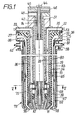
- Fig. 1 einen Plasmabrenner im Längsschnitt,
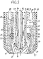
- Fig. 2 den unteren Teil der aus Elektrode und Düsenendstück gebildeten Elektrodenlanze in einem auszugsweisen Längsschnitt in vergrößerter Darstellung,
- Fig. 3 die Befestigung des Brennermantels in einem auszugsweisen Längsschnitt in vergrößerter Darstellung,
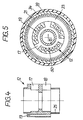
- Fig. 4 das Verbindungsstück zwischen dem an eine Spannungsquelle angeschlossenen Rohr und der Elektrode im Längsschnitt und
- Fig. 5 einen auszugsweisen Querschnitt durch die Elektrodenlanze längs der Linie V-V in Fig. 1.
- 1 shows a plasma torch in longitudinal section,
- 2 shows the lower part of the electrode lance formed from the electrode and nozzle end piece in a partial longitudinal section in an enlarged view,
- 3 the fastening of the burner jacket in a partial longitudinal section in an enlarged view,
- Fig. 4 shows the connector between the tube connected to a voltage source and the electrode in longitudinal section and
- 5 shows an excerpted cross section through the electrode lance along the line VV in FIG. 1.
Der Plasmabrenner besteht im wesentlichen aus einer Elektrodenlanze und einem Brennermantel. Die Elektrodenlanze besteht wiederum im wesentlichen aus einer Elektrode 10 und einem Düsenstutzen oder Düsenendstück 11 sowie den diese haltenden Teilen. Die Elektrode 10 weist eine schwach konische Endfläche und der Düsenstutzen 11 eine schwach konische Innenfläche und eine stärker konische Außenfläche auf.The plasma torch essentially consists of an electrode lance and a torch jacket. The electrode lance again consists essentially of an
Die Elektrode 10 ist mit ihrer Außenwand über ein im wesentlichen hülsenförmiges Verbindungsstück 12 mit dem Stromrohr 13, einem an die Hauptspannungsquelle angeschlossenen Rohr, befestigt, wobei zwischen der Elektrode 10 und dem Verbindungsstück 12 und zwischen diesem und dem Stromrohr 13 je eine Gewindeverbindung oder -paarung besteht.The
Die Innenwand der Elektrode 10 ist gleitend an einem im rückwärtigen Ende des Plasmabrenners befestigten Innenrohr 14 geführt. Zwischen dem Stromrohr 13 und dem Innenrohr 14 befindet sich ein Mittelrohr 15 aus Kunststoff zur Trennung der Teilkreisläufe des Kühlmittels für die Elektrode. In seinem unteren Bereich dient das Mittelrohr 15 auch zum Umlenken des Kühlmittelflusses.The inner wall of the
Die Innenwand des Düsenendstücks 11 ist über eine Gewindeverbindung mit einem Ringkörper 16 aus Isolationsmaterial, vorzugsweise Keramik, und dieser wiederum über eine Gewindeverbindung mit dem Verbindungsstück 12 verbunden.The inner wall of the
Das Verbindungsstück 12 (vgl. Fig. 4 und 5) weist, an seinem Umfang gleichmäßig verteilt, obere und untere radiale Durchlässe 17, 18 und parallel zur Brennerachse verlaufende Durchlässe 19 auf.The connecting piece 12 (cf. FIGS. 4 and 5) has upper and lower
Oberhalb der oberen radialen Durchlässe 17 ist der Innenflansch einer Hülse 21 aus Kunststoff und zwischen den oberen und unteren radialen Durchlässen 17, 18 der Innenflansch eines Mittelrohres 23 über jeweils eine Gewindepaarung mit dem Verbindungsstück 12 verschraubt.Above the upper
Der an einem unteren hülsenförmigen Vorsprung 25 des Verbindungsstücks 12 angeschraubte Ringkörper 16, an dem wiederum das Düsenendstück 11 angeschraubt ist, weist parallel zur Achse des Brenners verlaufende Durchlässe 26 auf, die in Leitungsverbindung zu den Durchlässen 19 des Verbindungsstücks 12 stehen. Nach unten weisen die Durchlässe 26 in den Ringspalt 27 zwischen der Elektrode 10 und dem Düsenendstück 11.The
Um das Stromrohr 13 ist ein Kunststoffrohr 28 angeordnet, das parallel zur Achse des Brenners verlaufende Durchlässe 29 aufweist, die im unteren Bereich des Rohres 28 in einen ringförmigen Hohlraum 31 übergehen, der eine Verbindung zu den Durchlässen 19 des Verbindungsstücks 16 herstellt. An seinem oberen Ende ist das Rohr 28 mit einem Flansch 32 versehen, der radiale Durchlässe 33 aufweist, die mit den achsparallelen Durchlässen 29 in Verbindung stehen. Das Kunststoffrohr 28 ist zur Erhöhung der Stabilität von einem Stahlrohr 34 mit einem Flansch 35 umgeben. Der Außendurchmesser des Stahlrohrs 34 entspricht dem Außendurchmesser des Düsenendstücks 11. An der Außenseite des Stahlrohrs 34 ist ein Isolationsrohr 36 angeordnet, das an seinem oberen Ende einen Flansch 37 aufweist. Zwischen der zylindrischen Mantelfläche des Isolationsrohrs 36 und der Unterseite des Flansches 37 ist eine Übergangsfläche 38 vorgesehen. Ein weiteres unteres Keramikrohr 39 liegt mit seiner Innenfläche an den Außenflächen des Stahlrohrs 34 und des Düsenendstücks 11 an und ist über eine Schraub- bzw. Gewindeverbindung lösbar mit dem oberen Isolationsrohr 36 verbunden. An seinem unteren Ende ist die Außenfläche des unteren Keramikrohrs 39 stufenfrei in die konische Außenfläche des Düsenendstücks 11 überführt.Arranged around the
Durch das Innenrohr 14 der Elektrodenlanze ist eine Hilfselektrode 42 geführt, die in bekannter Weise durch Distanzstücke zentriert ist. An ihrem oberen Ende weist die Hilfselektrode 42 einen Stromanschluß 44 für den Zündstrom auf. Elektrisch ist die Hilfselektrode 42 in ihrem oberen Bereich durch eine Kunststoffscheibe 45 von dem Innenrohr 14 und den übrigen Teilen der Elektrodenlanze getrennt. Die Kunststoffscheibe 45 weist einen oder mehrere radiale Durchlässe 46 zum Zuführen von Zündgas auf, das weiterhin durch den durch die Zündelektrode 42 und das Innenrohr 14 gebildeten Ringkanal fließen kann.An
Die Elektrode 10 und das Düsenendstück 11 werden von einem gemeinsamen, kombinierten Kühlmittelkreislauf gekühlt. Von dem Kühlmitteleintritt 48 gelangt das Kühlmittel durch den durch das Innenrohr 14 und das Mittelrohr 15 gebildeten Ringkanal 49, wird unten am Mittelrohr 15 umgelenkt, fließt durch die radialen Durchlässe 18, wird durch das Umlenkteil 24 umgelenkt und fließt durch die Durchlässe 17 und den durch das Stromrohr 13 und das Mittelrohr 15 gebildeten Ringkanal 50 zum Kühlmittelaustritt 51.The
Alle bisher beschriebenen Teile bilden zusammen die Elektrodenlanze.All the parts described so far together form the electrode lance.
Von einem Isolierring 53 aus Kunststoff elektrisch getrennt, ist ein Gehäuseteil 54 an der Außenseite des Flansches 37 zentriert und mit dem Flansch 32 des Kunststoffrohrs 28 mechanisch fest verbunden.Electrically separated from an insulating
Das Gehäuseteil 54 weist einen Anschluß für eine tangentiale Zuleitung 55 auf, die mit einer Druckgasquelle 56 für Hüllgas verbunden ist. An seiner Innenseite weist das Gehäuseteil 54 einen nach unten gerichteten zylindrischen Flansch 57 auf (vgl. Fig 3). Unter dem Gehäuseteil 54 ist ein sog. Rohrverbinder 58 befestigt, der einen Kühlmittelzu- und -ablauf 61, 62 aufweist. An dem Rohrverbinder 58 ist wiederum ein äußeres Mantelrohr 63 über seinen Flansch 64 befestigt. An dem unteren Ende des Mantelrohrs 63 ist ein Verbindungsstück 65 lösbar befestigt. An einem Innengewinde des Zwischenstücks 65 sind ein oberes Mittelrohr 66, ein Innenrohr 72 und ein unteres Mittel-und Trennrohr 67 und an einem Außengewinde des Zwischenstücks 65 ein Düsenmantel 68 samt Innenwand 69 lösbar befestigt. Das Zwischenstück 65 weist parallel zur Achse des Brenners ausgerichtete Durchlässe 71 für das Kühlmedium des Brennermantels auf. Die obere Mittelwand 66 ist mit dem oberen Teil ihrer Außenfläche druckfest gleitend an einer Innenfläche des Rohrverbinders 58 geführt. An dem Innenrohr 72 ist die Innenwand des Düsenmantels 68 gleitend geführt. Das Innenrohr 72 des Brennermantels 73 ist mit seinem oberen Ende druckfest gleitend an dem zylindrischen Flansch 57 des Gehäuses 54 geführt.The
Alle im Anschluß an die Elektrodenlanze beschriebenen Teile vom Gehäuse 54 bis zum Düsenmantel 68 bilden zusammen den Brennermantel 73 als eine Baueinheit.All parts described in connection with the electrode lance from the
Die gesamte Außenfläche des Brennermantels 73 ist spalt- und stufenfrei ausgeführt und schafft damit gute Voraussetzungen für die Abdichtung in der Gefäßdurchführung, eine gute Gleichmäßigkeit der Kühlung und auch für das Verhindern parasitärer Bogenansätze.The entire outer surface of the
Zwischen dem Isolationsrohr 36, das die Außenwand der Elektrodenlanze bildet, und dem Brennermantel 73 wird ein ringförmiger Kanal 75 gebildet, der über den größten Teil seiner Länge parallel zur Hauptachse des Brenners verläuft und im Bereich vor der Stirnfläche des Düsenendstücks 11 einen konischen Verlauf 76 aufweist. Der konische Verlauf 76 des Ringkanals 75 im Mündungsbereich wird durch die Außenfläche des Düsenendstücks 11 und eine konische Innenfläche des Düsenmantels 68 gebildet. Beide konischen Flächen weisen einen Überzug 77 bzw. 78 aus Keramik auf.Between the
Der lichte Durchmesser des Düsenmantels 68 an seiner Stirnfläche ist kleiner als der Außendurchmesser des Düsenendstücks 11, so daß die Stirnfläche des gekühlten Düsenmantels 68 für das Keramikrohr 39 einen Hitzeschutz gegen die den Plasmabrenner bzw. den Brennerbogen umgebende heiße Atmosphäre darstellt.The inside diameter of the
Insbesondere bei großen Plasmabrennerlängen und/oder schrägen Einbaulagen sind an dem die Elektrodenlanze umfassenden Isolationsrohr 36 Distanz- oder Stützkörper 80 befestigt, die bis an das Innenrohr 72 des Brennermantels heranreichen.In particular in the case of large plasma torch lengths and / or inclined installation positions, spacer or
Daneben können an dem Isolationsrohr 36 auch Verdrängerkörper 81 (Fig. 3) befestigt sein.In addition, displacement body 81 (FIG. 3) can also be attached to the
Claims (19)
dadurch gekennzeichnet,
daß der Ringkanal (75) zwischen dem Düsenendstück (11) und dem Brennermantel (73) mindestens bis zur Höhe des Kühlmittelein-und Auslaufs (61, 62) des Brennermantels (73) zurückgezogen ist und an seinem rückwärtigen Ende eine Leitungsverbindung (55) mit einer Quelle (56) eines unter Druck stehenden gasförmigen Mediums aufweist.1. Plasma torch for transmitted arc with a central electrode, a concentric nozzle end piece, wherein an annular gap for the passage of plasma gas is present between the electrode and the nozzle end piece, and a concentric burner jacket with outer, middle and inner wall, being between the nozzle end piece and the There is an annular channel in the burner jacket, the inner wall of which is partly formed by an insulating tube which electrically separates the two parts,
characterized,
that the annular channel (75) between the nozzle end piece (11) and the burner jacket (73) is withdrawn at least up to the height of the coolant inlet and outlet (61, 62) of the burner jacket (73) and at its rear end a line connection (55) with a source (56) of a pressurized gaseous medium.
Applications Claiming Priority (2)
| Application Number | Priority Date | Filing Date | Title |
|---|---|---|---|
| DE4022111A DE4022111A1 (en) | 1990-07-11 | 1990-07-11 | PLASMA TORCH FOR TRANSFERED ARC |
| DE4022111 | 1990-07-11 |
Publications (3)
| Publication Number | Publication Date |
|---|---|
| EP0465941A2 true EP0465941A2 (en) | 1992-01-15 |
| EP0465941A3 EP0465941A3 (en) | 1992-07-01 |
| EP0465941B1 EP0465941B1 (en) | 1997-04-23 |
Family
ID=6410097
Family Applications (1)
| Application Number | Title | Priority Date | Filing Date |
|---|---|---|---|
| EP91110640A Expired - Lifetime EP0465941B1 (en) | 1990-07-11 | 1991-06-27 | Plasma torch with transferred arc |
Country Status (11)
| Country | Link |
|---|---|
| US (1) | US5206481A (en) |
| EP (1) | EP0465941B1 (en) |
| JP (1) | JPH04229995A (en) |
| KR (1) | KR100203089B1 (en) |
| AT (1) | ATE152314T1 (en) |
| CA (1) | CA2045844A1 (en) |
| DE (2) | DE4022111A1 (en) |
| ES (1) | ES2100184T3 (en) |
| FI (1) | FI103250B (en) |
| NO (1) | NO912474L (en) |
| ZA (1) | ZA915358B (en) |
Cited By (3)
| Publication number | Priority date | Publication date | Assignee | Title |
|---|---|---|---|---|
| EP0510816A3 (en) * | 1991-04-25 | 1993-01-07 | Tetronics Research & Development Company Limited | Process and apparatus for the production of fused silica |
| DE4440323A1 (en) * | 1994-11-11 | 1996-05-15 | Sulzer Metco Ag | Nozzle for a torch head of a plasma spraying unit |
| EP0748149A1 (en) * | 1995-06-05 | 1996-12-11 | The Esab Group, Inc. | Plasma arc torch having water injection nozzle assembly |
Families Citing this family (22)
| Publication number | Priority date | Publication date | Assignee | Title |
|---|---|---|---|---|
| DE4034731A1 (en) * | 1990-10-30 | 1992-05-07 | Mannesmann Ag | PLASMA BURNER FOR MELTING AND KEEPING WARM MATERIALS TO BE TREATED |
| US5455401A (en) * | 1994-10-12 | 1995-10-03 | Aerojet General Corporation | Plasma torch electrode |
| FR2735939B1 (en) * | 1995-06-20 | 1997-09-26 | Aerospatiale | EXTERNAL COOLING DEVICE OF A PLASMA TORCH |
| CZ301353B6 (en) * | 2002-04-19 | 2010-01-27 | Thermal Dynamics Corporation | Plasma arc torch tip, plasma torch including such tip and method of operating the plasma arc torch |
| JP2005118816A (en) * | 2003-10-16 | 2005-05-12 | Koike Sanso Kogyo Co Ltd | Nozzle for plasma torch |
| KR100886872B1 (en) | 2007-06-22 | 2009-03-06 | 홍용철 | Plasma burner |
| US8257455B2 (en) * | 2007-07-30 | 2012-09-04 | Korea Institute Of Machinery & Materials | Plasma burner and diesel particulate filter trap |
| TWI352368B (en) * | 2007-09-21 | 2011-11-11 | Ind Tech Res Inst | Plasma head and plasma-discharging device using th |
| IT1392379B1 (en) * | 2008-12-24 | 2012-03-02 | Cebora Spa | HIGH-PERFORMANCE PLASMA TORCH. |
| DE102009009451A1 (en) * | 2009-02-13 | 2010-08-19 | Siemens Aktiengesellschaft | Switchgear assembly with a switching path |
| DE102009031857C5 (en) * | 2009-07-03 | 2017-05-11 | Kjellberg Finsterwalde Plasma Und Maschinen Gmbh | Nozzle for a liquid-cooled plasma torch and plasma torch head with the same |
| SI2449862T1 (en) | 2009-07-03 | 2015-12-31 | Kjellberg Finsterwalde Plasma Und Maschinen Gmbh | Nozzle for a liquid-cooled plasma torch and plasma torch head having the same |
| ITBO20120375A1 (en) * | 2012-07-11 | 2014-01-12 | Tec Mo S R L | COOLED PLASMA TORCH DEVICE |
| DE102012213453A1 (en) * | 2012-07-31 | 2014-02-06 | Siemens Aktiengesellschaft | Torch for tungsten inert gas welding |
| DE102013103508A1 (en) * | 2013-04-09 | 2014-10-09 | PLASMEQ GmbH | plasma torch |
| US9144148B2 (en) | 2013-07-25 | 2015-09-22 | Hypertherm, Inc. | Devices for gas cooling plasma arc torches and related systems and methods |
| WO2016023112A1 (en) * | 2014-08-11 | 2016-02-18 | Best Theratronics Ltd. | System and method for metallic isotope separation by a combined thermal-vacuum distillation process |
| DE102014219275A1 (en) * | 2014-09-24 | 2016-03-24 | Siemens Aktiengesellschaft | Ignition of flames of an electropositive metal by plasmatization of the reaction gas |
| MX2018011668A (en) * | 2016-04-11 | 2019-05-30 | Hypertherm Inc | Plasma arc cutting system, including nozzles and other consumables, and related operational methods. |
| GB2568106B (en) * | 2017-11-07 | 2022-09-21 | Tetronics Tech Limited | Plasma Torch Assembly |
| CN110056893A (en) * | 2019-05-21 | 2019-07-26 | 成都高鑫焊割科技有限公司 | A kind of pernicious gas burning cracking processor |
| CZ309391B6 (en) * | 2021-09-24 | 2022-11-09 | Thermacut, K.S. | Plasma torch guide, assembly and plasma torch |
Citations (3)
| Publication number | Priority date | Publication date | Assignee | Title |
|---|---|---|---|---|
| US4564740A (en) * | 1978-01-09 | 1986-01-14 | Institut Elektrosvarki Imeni E. O. Patona Akademii Nauk Ukrainskoi Ssr | Method of generating plasma in a plasma-arc torch and an arrangement for effecting same |
| EP0168810A1 (en) * | 1984-07-18 | 1986-01-22 | Süddeutsche Kühlerfabrik Julius Fr. Behr GmbH & Co. KG | Torch for plasma-MIG welding |
| EP0339563A2 (en) * | 1988-04-26 | 1989-11-02 | Nippon Steel Corporation | Transfer-type plasma torch |
Family Cites Families (13)
| Publication number | Priority date | Publication date | Assignee | Title |
|---|---|---|---|---|
| US3147329A (en) * | 1955-07-26 | 1964-09-01 | Union Carbide Corp | Method and apparatus for heating metal melting furnaces |
| NO119341B (en) * | 1965-04-09 | 1970-05-04 | Inst Badan Jadrowych | |
| US4082914A (en) * | 1973-05-14 | 1978-04-04 | Nikolai Iosifovich Bortnichuk | Method of stabilizing arc voltage in plasma arc furnace and apparatus for effecting same |
| CH593754A5 (en) * | 1976-01-15 | 1977-12-15 | Castolin Sa | |
| SU766088A1 (en) * | 1978-07-14 | 1982-06-23 | Всесоюзный Научно-Исследовательский Институт По Монтажным И Специальным Строительным Работам | Torch for arc treatment |
| CA1173784A (en) * | 1981-07-30 | 1984-09-04 | William H. Gauvin | Transferred-arc plasma reactor for chemical and metallurgical applications |
| DE3328777A1 (en) * | 1983-08-10 | 1985-02-28 | Fried. Krupp Gmbh, 4300 Essen | PLASMA TORCHER AND METHOD FOR OPERATING IT |
| US4628177A (en) * | 1984-08-10 | 1986-12-09 | B & B Precision Machines, Inc. | Arc welding torch |
| DE3435680A1 (en) * | 1984-09-28 | 1986-04-03 | Fried. Krupp Gmbh, 4300 Essen | PLASMA TORCH |
| US5132512A (en) * | 1988-06-07 | 1992-07-21 | Hypertherm, Inc. | Arc torch nozzle shield for plasma |
| JPH0220667A (en) * | 1988-07-06 | 1990-01-24 | Origin Electric Co Ltd | Plasma torch |
| JPH082500B2 (en) * | 1988-07-27 | 1996-01-17 | 松下電器産業株式会社 | Plasma cutting torch |
| US5124525A (en) * | 1991-08-27 | 1992-06-23 | Esab Welding Products, Inc. | Plasma arc torch having improved nozzle assembly |
-
1990
- 1990-07-11 DE DE4022111A patent/DE4022111A1/en not_active Withdrawn
-
1991
- 1991-06-20 FI FI913024A patent/FI103250B/en active
- 1991-06-25 NO NO91912474A patent/NO912474L/en unknown
- 1991-06-27 ES ES91110640T patent/ES2100184T3/en not_active Expired - Lifetime
- 1991-06-27 EP EP91110640A patent/EP0465941B1/en not_active Expired - Lifetime
- 1991-06-27 AT AT91110640T patent/ATE152314T1/en not_active IP Right Cessation
- 1991-06-27 DE DE59108674T patent/DE59108674D1/en not_active Expired - Fee Related
- 1991-06-27 CA CA002045844A patent/CA2045844A1/en not_active Abandoned
- 1991-07-02 US US07/725,628 patent/US5206481A/en not_active Expired - Fee Related
- 1991-07-09 JP JP3168416A patent/JPH04229995A/en active Pending
- 1991-07-10 ZA ZA915358A patent/ZA915358B/en unknown
- 1991-07-11 KR KR1019910011761A patent/KR100203089B1/en not_active IP Right Cessation
Patent Citations (3)
| Publication number | Priority date | Publication date | Assignee | Title |
|---|---|---|---|---|
| US4564740A (en) * | 1978-01-09 | 1986-01-14 | Institut Elektrosvarki Imeni E. O. Patona Akademii Nauk Ukrainskoi Ssr | Method of generating plasma in a plasma-arc torch and an arrangement for effecting same |
| EP0168810A1 (en) * | 1984-07-18 | 1986-01-22 | Süddeutsche Kühlerfabrik Julius Fr. Behr GmbH & Co. KG | Torch for plasma-MIG welding |
| EP0339563A2 (en) * | 1988-04-26 | 1989-11-02 | Nippon Steel Corporation | Transfer-type plasma torch |
Cited By (4)
| Publication number | Priority date | Publication date | Assignee | Title |
|---|---|---|---|---|
| EP0510816A3 (en) * | 1991-04-25 | 1993-01-07 | Tetronics Research & Development Company Limited | Process and apparatus for the production of fused silica |
| DE4440323A1 (en) * | 1994-11-11 | 1996-05-15 | Sulzer Metco Ag | Nozzle for a torch head of a plasma spraying unit |
| EP0748149A1 (en) * | 1995-06-05 | 1996-12-11 | The Esab Group, Inc. | Plasma arc torch having water injection nozzle assembly |
| US5660743A (en) * | 1995-06-05 | 1997-08-26 | The Esab Group, Inc. | Plasma arc torch having water injection nozzle assembly |
Also Published As
| Publication number | Publication date |
|---|---|
| EP0465941A3 (en) | 1992-07-01 |
| DE4022111A1 (en) | 1992-01-23 |
| ZA915358B (en) | 1992-04-29 |
| FI103250B1 (en) | 1999-05-14 |
| NO912474L (en) | 1992-01-13 |
| KR920003820A (en) | 1992-02-29 |
| US5206481A (en) | 1993-04-27 |
| EP0465941B1 (en) | 1997-04-23 |
| FI913024A0 (en) | 1991-06-20 |
| KR100203089B1 (en) | 1999-06-15 |
| JPH04229995A (en) | 1992-08-19 |
| DE59108674D1 (en) | 1997-05-28 |
| CA2045844A1 (en) | 1992-01-12 |
| FI103250B (en) | 1999-05-14 |
| NO912474D0 (en) | 1991-06-25 |
| ATE152314T1 (en) | 1997-05-15 |
| FI913024A (en) | 1992-01-12 |
| ES2100184T3 (en) | 1997-06-16 |
Similar Documents
| Publication | Publication Date | Title |
|---|---|---|
| EP0465941B1 (en) | Plasma torch with transferred arc | |
| DE4132850C2 (en) | Burners for the combustion of fine-grained to dusty solid fuels | |
| DE2912843A1 (en) | PLASMA BURNER, PLASMA BURNER ARRANGEMENT AND METHOD FOR PLASMA PRODUCTION | |
| EP0538293B1 (en) | Plasma burner for transferred arc | |
| DD151401A1 (en) | BY MEANS OF GAS MIXED PLASMABRENNER | |
| EP0176004B1 (en) | Plasma torch | |
| DE2818304A1 (en) | METHOD AND DEVICE FOR PLASMA INJECTION OF A COATING MATERIAL ON A BASE | |
| DE2416422A1 (en) | METHOD AND DEVICE FOR ARC WELDING | |
| DE4030541C2 (en) | Burner for coating base materials with powdered filler materials | |
| DE2839485A1 (en) | TORCH FOR MICROPLASMA WELDING | |
| DE3241476A1 (en) | METHOD FOR INTRODUCING IONIZABLE GAS INTO A PLASMA OF AN ARC BURNER, AND PLASMA TORCHER FOR CARRYING OUT THE METHOD | |
| DE2818303A1 (en) | METHOD AND DEVICE FOR PLASMA INJECTION OF A COATING MATERIAL ON A BASE | |
| EP0168810B1 (en) | Torch for plasma-mig welding | |
| DE2633510C3 (en) | Plasmatron | |
| DE1592445B2 (en) | Process and device for the production of titanium dioxide by vapor phase oxidation of titanium tetrachloride | |
| DE1764116B1 (en) | ARC PLASMA RAY GENERATOR | |
| DD292806A5 (en) | LIQUID-COOLED PLASMA BURNER WITH TRANSMITTED ARC | |
| DE1546810A1 (en) | Device for ejecting powdery material by means of an ionized gas jet | |
| DE1286241B (en) | Inductive plasma torch | |
| EP0094984A1 (en) | Arc welding or cutting torch | |
| DE102006029725B4 (en) | Method and device for introducing dusts into a molten metal of a pyrometallurgical plant | |
| DE1075765B (en) | Arc torch with non-consumable electrode and gas-encased, constricted arc | |
| EP0352433A2 (en) | Burner, particularly for automatic operation | |
| EP0183978A2 (en) | Burner | |
| EP0411272A1 (en) | Gas-shielded torch |
Legal Events
| Date | Code | Title | Description |
|---|---|---|---|
| PUAI | Public reference made under article 153(3) epc to a published international application that has entered the european phase |
Free format text: ORIGINAL CODE: 0009012 |
|
| AK | Designated contracting states |
Kind code of ref document: A2 Designated state(s): AT BE DE ES FR GB IT LU NL SE |
|
| PUAL | Search report despatched |
Free format text: ORIGINAL CODE: 0009013 |
|
| AK | Designated contracting states |
Kind code of ref document: A3 Designated state(s): AT BE DE ES FR GB IT LU NL SE |
|
| 17P | Request for examination filed |
Effective date: 19921208 |
|
| 17Q | First examination report despatched |
Effective date: 19950210 |
|
| RAP1 | Party data changed (applicant data changed or rights of an application transferred) |
Owner name: FRIED. KRUPP AG HOESCH-KRUPP |
|
| GRAG | Despatch of communication of intention to grant |
Free format text: ORIGINAL CODE: EPIDOS AGRA |
|
| GRAH | Despatch of communication of intention to grant a patent |
Free format text: ORIGINAL CODE: EPIDOS IGRA |
|
| GRAH | Despatch of communication of intention to grant a patent |
Free format text: ORIGINAL CODE: EPIDOS IGRA |
|
| GRAA | (expected) grant |
Free format text: ORIGINAL CODE: 0009210 |
|
| AK | Designated contracting states |
Kind code of ref document: B1 Designated state(s): AT BE DE ES FR GB IT LU NL SE |
|
| REF | Corresponds to: |
Ref document number: 152314 Country of ref document: AT Date of ref document: 19970515 Kind code of ref document: T |
|
| GBT | Gb: translation of ep patent filed (gb section 77(6)(a)/1977) |
Effective date: 19970424 |
|
| REF | Corresponds to: |
Ref document number: 59108674 Country of ref document: DE Date of ref document: 19970528 |
|
| REG | Reference to a national code |
Ref country code: ES Ref legal event code: FG2A Ref document number: 2100184 Country of ref document: ES Kind code of ref document: T3 |
|
| ET | Fr: translation filed | ||
| PLBE | No opposition filed within time limit |
Free format text: ORIGINAL CODE: 0009261 |
|
| STAA | Information on the status of an ep patent application or granted ep patent |
Free format text: STATUS: NO OPPOSITION FILED WITHIN TIME LIMIT |
|
| 26N | No opposition filed | ||
| PGFP | Annual fee paid to national office [announced via postgrant information from national office to epo] |
Ref country code: GB Payment date: 19980514 Year of fee payment: 8 |
|
| PGFP | Annual fee paid to national office [announced via postgrant information from national office to epo] |
Ref country code: NL Payment date: 19980518 Year of fee payment: 8 Ref country code: FR Payment date: 19980518 Year of fee payment: 8 |
|
| PGFP | Annual fee paid to national office [announced via postgrant information from national office to epo] |
Ref country code: SE Payment date: 19980525 Year of fee payment: 8 |
|
| PGFP | Annual fee paid to national office [announced via postgrant information from national office to epo] |
Ref country code: AT Payment date: 19980527 Year of fee payment: 8 |
|
| PGFP | Annual fee paid to national office [announced via postgrant information from national office to epo] |
Ref country code: BE Payment date: 19980615 Year of fee payment: 8 |
|
| PGFP | Annual fee paid to national office [announced via postgrant information from national office to epo] |
Ref country code: ES Payment date: 19980616 Year of fee payment: 8 |
|
| PGFP | Annual fee paid to national office [announced via postgrant information from national office to epo] |
Ref country code: LU Payment date: 19980922 Year of fee payment: 8 |
|
| PG25 | Lapsed in a contracting state [announced via postgrant information from national office to epo] |
Ref country code: LU Free format text: LAPSE BECAUSE OF NON-PAYMENT OF DUE FEES Effective date: 19990627 Ref country code: GB Free format text: LAPSE BECAUSE OF NON-PAYMENT OF DUE FEES Effective date: 19990627 Ref country code: AT Free format text: LAPSE BECAUSE OF NON-PAYMENT OF DUE FEES Effective date: 19990627 |
|
| PG25 | Lapsed in a contracting state [announced via postgrant information from national office to epo] |
Ref country code: ES Free format text: LAPSE BECAUSE OF EXPIRATION OF PROTECTION Effective date: 19990628 |
|
| PG25 | Lapsed in a contracting state [announced via postgrant information from national office to epo] |
Ref country code: SE Free format text: THE PATENT HAS BEEN ANNULLED BY A DECISION OF A NATIONAL AUTHORITY Effective date: 19990629 |
|
| PG25 | Lapsed in a contracting state [announced via postgrant information from national office to epo] |
Ref country code: FR Free format text: THE PATENT HAS BEEN ANNULLED BY A DECISION OF A NATIONAL AUTHORITY Effective date: 19990630 Ref country code: BE Free format text: LAPSE BECAUSE OF NON-PAYMENT OF DUE FEES Effective date: 19990630 |
|
| PGFP | Annual fee paid to national office [announced via postgrant information from national office to epo] |
Ref country code: DE Payment date: 19990804 Year of fee payment: 9 |
|
| BERE | Be: lapsed |
Owner name: FRIED. KRUPP A.G. HOESCH-KRUPP Effective date: 19990630 |
|
| PG25 | Lapsed in a contracting state [announced via postgrant information from national office to epo] |
Ref country code: NL Free format text: LAPSE BECAUSE OF NON-PAYMENT OF DUE FEES Effective date: 20000101 |
|
| GBPC | Gb: european patent ceased through non-payment of renewal fee |
Effective date: 19990627 |
|
| EUG | Se: european patent has lapsed |
Ref document number: 91110640.9 |
|
| NLV4 | Nl: lapsed or anulled due to non-payment of the annual fee |
Effective date: 20000101 |
|
| REG | Reference to a national code |
Ref country code: FR Ref legal event code: ST |
|
| PG25 | Lapsed in a contracting state [announced via postgrant information from national office to epo] |
Ref country code: DE Free format text: LAPSE BECAUSE OF NON-PAYMENT OF DUE FEES Effective date: 20010403 |
|
| REG | Reference to a national code |
Ref country code: ES Ref legal event code: FD2A Effective date: 20010601 |
|
| PG25 | Lapsed in a contracting state [announced via postgrant information from national office to epo] |
Ref country code: IT Free format text: LAPSE BECAUSE OF NON-PAYMENT OF DUE FEES;WARNING: LAPSES OF ITALIAN PATENTS WITH EFFECTIVE DATE BEFORE 2007 MAY HAVE OCCURRED AT ANY TIME BEFORE 2007. THE CORRECT EFFECTIVE DATE MAY BE DIFFERENT FROM THE ONE RECORDED. Effective date: 20050627 |