EP0465697B1 - Preparation of gas separation membrane and spiral wound gas separation module - Google Patents
Preparation of gas separation membrane and spiral wound gas separation module Download PDFInfo
- Publication number
- EP0465697B1 EP0465697B1 EP90113127A EP90113127A EP0465697B1 EP 0465697 B1 EP0465697 B1 EP 0465697B1 EP 90113127 A EP90113127 A EP 90113127A EP 90113127 A EP90113127 A EP 90113127A EP 0465697 B1 EP0465697 B1 EP 0465697B1
- Authority
- EP
- European Patent Office
- Prior art keywords
- membrane
- process according
- module
- container
- gas
- Prior art date
- Legal status (The legal status is an assumption and is not a legal conclusion. Google has not performed a legal analysis and makes no representation as to the accuracy of the status listed.)
- Expired - Lifetime
Links
- 239000012528 membrane Substances 0.000 title claims abstract description 105
- 238000000926 separation method Methods 0.000 title abstract description 19
- 239000002904 solvent Substances 0.000 claims abstract description 31
- 239000000463 material Substances 0.000 claims abstract description 18
- 238000004519 manufacturing process Methods 0.000 claims abstract description 3
- 239000007789 gas Substances 0.000 claims description 37
- IMNFDUFMRHMDMM-UHFFFAOYSA-N N-Heptane Chemical compound CCCCCCC IMNFDUFMRHMDMM-UHFFFAOYSA-N 0.000 claims description 30
- 238000000034 method Methods 0.000 claims description 26
- 230000008569 process Effects 0.000 claims description 26
- 239000004744 fabric Substances 0.000 claims description 19
- XLYOFNOQVPJJNP-UHFFFAOYSA-N water Substances O XLYOFNOQVPJJNP-UHFFFAOYSA-N 0.000 claims description 16
- KFZMGEQAYNKOFK-UHFFFAOYSA-N Isopropanol Chemical compound CC(C)O KFZMGEQAYNKOFK-UHFFFAOYSA-N 0.000 claims description 14
- 229920000728 polyester Polymers 0.000 claims description 12
- 229920002301 cellulose acetate Polymers 0.000 claims description 11
- 239000012530 fluid Substances 0.000 claims description 9
- 238000005266 casting Methods 0.000 claims description 8
- -1 polypropylene Polymers 0.000 claims description 8
- 229920001296 polysiloxane Polymers 0.000 claims description 7
- 238000004804 winding Methods 0.000 claims description 6
- 239000003960 organic solvent Substances 0.000 claims description 5
- 229920002492 poly(sulfone) Polymers 0.000 claims description 3
- 239000004952 Polyamide Substances 0.000 claims description 2
- 239000000835 fiber Substances 0.000 claims description 2
- 229910010272 inorganic material Inorganic materials 0.000 claims description 2
- 239000011147 inorganic material Substances 0.000 claims description 2
- 239000011368 organic material Substances 0.000 claims description 2
- 229920002647 polyamide Polymers 0.000 claims description 2
- 229920000515 polycarbonate Polymers 0.000 claims description 2
- 239000004417 polycarbonate Substances 0.000 claims description 2
- 229920006380 polyphenylene oxide Polymers 0.000 claims description 2
- 229920002981 polyvinylidene fluoride Polymers 0.000 claims description 2
- 230000008439 repair process Effects 0.000 claims description 2
- 239000011261 inert gas Substances 0.000 claims 2
- 239000010410 layer Substances 0.000 claims 2
- 239000004743 Polypropylene Substances 0.000 claims 1
- 229920002521 macromolecule Polymers 0.000 claims 1
- 229920001155 polypropylene Polymers 0.000 claims 1
- 238000010926 purge Methods 0.000 claims 1
- 239000002356 single layer Substances 0.000 claims 1
- 229920001059 synthetic polymer Polymers 0.000 claims 1
- 238000001035 drying Methods 0.000 description 15
- IJGRMHOSHXDMSA-UHFFFAOYSA-N Atomic nitrogen Chemical compound N#N IJGRMHOSHXDMSA-UHFFFAOYSA-N 0.000 description 6
- DNIAPMSPPWPWGF-UHFFFAOYSA-N Propylene glycol Chemical compound CC(O)CO DNIAPMSPPWPWGF-UHFFFAOYSA-N 0.000 description 6
- 239000000203 mixture Substances 0.000 description 6
- 238000000137 annealing Methods 0.000 description 4
- 230000003014 reinforcing effect Effects 0.000 description 4
- 238000005096 rolling process Methods 0.000 description 4
- QTBSBXVTEAMEQO-UHFFFAOYSA-N Acetic acid Chemical compound CC(O)=O QTBSBXVTEAMEQO-UHFFFAOYSA-N 0.000 description 3
- OKKJLVBELUTLKV-UHFFFAOYSA-N Methanol Chemical compound OC OKKJLVBELUTLKV-UHFFFAOYSA-N 0.000 description 3
- QVGXLLKOCUKJST-UHFFFAOYSA-N atomic oxygen Chemical compound [O] QVGXLLKOCUKJST-UHFFFAOYSA-N 0.000 description 3
- 238000005336 cracking Methods 0.000 description 3
- 229910052757 nitrogen Inorganic materials 0.000 description 3
- 239000001301 oxygen Substances 0.000 description 3
- 229910052760 oxygen Inorganic materials 0.000 description 3
- 239000012783 reinforcing fiber Substances 0.000 description 3
- CSCPPACGZOOCGX-UHFFFAOYSA-N Acetone Chemical compound CC(C)=O CSCPPACGZOOCGX-UHFFFAOYSA-N 0.000 description 2
- 229920001747 Cellulose diacetate Polymers 0.000 description 2
- 229920002284 Cellulose triacetate Polymers 0.000 description 2
- LFQSCWFLJHTTHZ-UHFFFAOYSA-N Ethanol Chemical compound CCO LFQSCWFLJHTTHZ-UHFFFAOYSA-N 0.000 description 2
- UFHFLCQGNIYNRP-UHFFFAOYSA-N Hydrogen Chemical compound [H][H] UFHFLCQGNIYNRP-UHFFFAOYSA-N 0.000 description 2
- SECXISVLQFMRJM-UHFFFAOYSA-N N-Methylpyrrolidone Chemical compound CN1CCCC1=O SECXISVLQFMRJM-UHFFFAOYSA-N 0.000 description 2
- NNLVGZFZQQXQNW-ADJNRHBOSA-N [(2r,3r,4s,5r,6s)-4,5-diacetyloxy-3-[(2s,3r,4s,5r,6r)-3,4,5-triacetyloxy-6-(acetyloxymethyl)oxan-2-yl]oxy-6-[(2r,3r,4s,5r,6s)-4,5,6-triacetyloxy-2-(acetyloxymethyl)oxan-3-yl]oxyoxan-2-yl]methyl acetate Chemical compound O([C@@H]1O[C@@H]([C@H]([C@H](OC(C)=O)[C@H]1OC(C)=O)O[C@H]1[C@@H]([C@@H](OC(C)=O)[C@H](OC(C)=O)[C@@H](COC(C)=O)O1)OC(C)=O)COC(=O)C)[C@@H]1[C@@H](COC(C)=O)O[C@@H](OC(C)=O)[C@H](OC(C)=O)[C@H]1OC(C)=O NNLVGZFZQQXQNW-ADJNRHBOSA-N 0.000 description 2
- 239000002253 acid Substances 0.000 description 2
- 239000011521 glass Substances 0.000 description 2
- 239000001257 hydrogen Substances 0.000 description 2
- 229910052739 hydrogen Inorganic materials 0.000 description 2
- 239000007788 liquid Substances 0.000 description 2
- VNWKTOKETHGBQD-UHFFFAOYSA-N methane Chemical compound C VNWKTOKETHGBQD-UHFFFAOYSA-N 0.000 description 2
- 230000035699 permeability Effects 0.000 description 2
- 239000012466 permeate Substances 0.000 description 2
- 238000002791 soaking Methods 0.000 description 2
- RYHBNJHYFVUHQT-UHFFFAOYSA-N 1,4-Dioxane Chemical compound C1COCCO1 RYHBNJHYFVUHQT-UHFFFAOYSA-N 0.000 description 1
- 239000004677 Nylon Substances 0.000 description 1
- 239000004642 Polyimide Substances 0.000 description 1
- OFOBLEOULBTSOW-UHFFFAOYSA-N Propanedioic acid Natural products OC(=O)CC(O)=O OFOBLEOULBTSOW-UHFFFAOYSA-N 0.000 description 1
- WYURNTSHIVDZCO-UHFFFAOYSA-N Tetrahydrofuran Chemical compound C1CCOC1 WYURNTSHIVDZCO-UHFFFAOYSA-N 0.000 description 1
- 230000004075 alteration Effects 0.000 description 1
- 238000013459 approach Methods 0.000 description 1
- 238000006243 chemical reaction Methods 0.000 description 1
- 239000003795 chemical substances by application Substances 0.000 description 1
- 239000011248 coating agent Substances 0.000 description 1
- 238000000576 coating method Methods 0.000 description 1
- 230000000052 comparative effect Effects 0.000 description 1
- 230000006378 damage Effects 0.000 description 1
- 238000004108 freeze drying Methods 0.000 description 1
- 239000012510 hollow fiber Substances 0.000 description 1
- 238000002386 leaching Methods 0.000 description 1
- 238000012423 maintenance Methods 0.000 description 1
- VZCYOOQTPOCHFL-UPHRSURJSA-N maleic acid Chemical compound OC(=O)\C=C/C(O)=O VZCYOOQTPOCHFL-UPHRSURJSA-N 0.000 description 1
- 239000011976 maleic acid Substances 0.000 description 1
- 238000012986 modification Methods 0.000 description 1
- 230000004048 modification Effects 0.000 description 1
- 239000003345 natural gas Substances 0.000 description 1
- 229920001778 nylon Polymers 0.000 description 1
- 238000000614 phase inversion technique Methods 0.000 description 1
- 229920001721 polyimide Polymers 0.000 description 1
- 229920000306 polymethylpentene Polymers 0.000 description 1
- 239000011116 polymethylpentene Substances 0.000 description 1
- 238000000746 purification Methods 0.000 description 1
- 238000011084 recovery Methods 0.000 description 1
- 238000006467 substitution reaction Methods 0.000 description 1
- VZCYOOQTPOCHFL-UHFFFAOYSA-N trans-butenedioic acid Natural products OC(=O)C=CC(O)=O VZCYOOQTPOCHFL-UHFFFAOYSA-N 0.000 description 1
Images



Classifications
-
- B—PERFORMING OPERATIONS; TRANSPORTING
- B01—PHYSICAL OR CHEMICAL PROCESSES OR APPARATUS IN GENERAL
- B01D—SEPARATION
- B01D67/00—Processes specially adapted for manufacturing semi-permeable membranes for separation processes or apparatus
- B01D67/0081—After-treatment of organic or inorganic membranes
- B01D67/0095—Drying
-
- B—PERFORMING OPERATIONS; TRANSPORTING
- B01—PHYSICAL OR CHEMICAL PROCESSES OR APPARATUS IN GENERAL
- B01D—SEPARATION
- B01D53/00—Separation of gases or vapours; Recovering vapours of volatile solvents from gases; Chemical or biological purification of waste gases, e.g. engine exhaust gases, smoke, fumes, flue gases, aerosols
- B01D53/22—Separation of gases or vapours; Recovering vapours of volatile solvents from gases; Chemical or biological purification of waste gases, e.g. engine exhaust gases, smoke, fumes, flue gases, aerosols by diffusion
-
- B—PERFORMING OPERATIONS; TRANSPORTING
- B01—PHYSICAL OR CHEMICAL PROCESSES OR APPARATUS IN GENERAL
- B01D—SEPARATION
- B01D63/00—Apparatus in general for separation processes using semi-permeable membranes
- B01D63/10—Spiral-wound membrane modules
- B01D63/101—Spiral winding
Definitions
- the invention relates to a process for preparing gas separation membranes and modules.
- Gas separation membranes are films which exhibit a higher permeability toward some gases than toward others.
- Industries increasingly employ such membranes for such uses as: oxygen enrichment of air, purification of nitrogen, recovery of hydrogen from hydrogen reaction systems, removal of acid gases from natural gas or biogas, and separation of acid such as Co2 from H2S.
- Such membranes have no moving parts, negligible maintenance, low energy requirements, operational flexibility, and rapid start up and shut down. They may be formed as flat sheets, hollow fibers or tubes. A reinforcing fabric of woven or nonwoven polyester, or nylon increases membrane strength, improves operational properties and provides longer life.
- the rate at which gas permeates a membrane can be expressed as p/l, where p is the gas permeability, and l is the effective membrane thickness.
- Cellulose acetate exhibits particular commercial importance because its effective thickness is about 0.1 micrometers. This in turn, results in a relatively high gas permeation rate.
- Cloth reinforced membranes have been prepared by casting a cellulose acetate solution on the cloth and then gelling, leaching, annealing, solvent exchanging and drying the cloth/membrane combination.
- US-A-3 497 072 discloses a phase inversion technique for casting a cellulose acetate membrane. If a wet membrane is to be dried directly, the high surface tension of water will destroy the microporous structure. Drying methods which can prevent this destruction include first freeze drying; second adding an agent to reduce surface tension; and third exchanging the water solvent for another solvent.
- US-A-3 842 515 describes a solvent exchanging process which exchanges water with water missible alcohol, then exchanges the alcohol with a nonpolar organic solvent, and finally evaporates the nonpolar organic solvent to leave a dried membrane.
- US-A-4 080 743 describes a solvent exchanging process which first exchanges water with water missible organic solvents, and then evaporates the mixture to leave a dried membrane.
- the invention is a process for producing a gas separation membrane and module.
- Materials used for industrial gas separation membrane applications include cellulose acetate (CA), polysulfone, polyamide, polyimide, polycarbonate, polysiloxanes, poly (4-methyl-1-pentene), poly (phenylene oxide) and poly (vinylidene fluoride).
- FIG. 1 shows an example of such a spiral wound gas separation membrane 11 as disclosed in US-A-4 134 742.
- the module comprises a multilayer membrane sheet 13 wound onto a hollow core member 15 having perforations 17.
- the multilayer membrane sheet 13 consists of two layers of cloth reinforced membrane 19 separated by a layer of tricot netting 21. Each layer of reinforced membrane 19 is covered by an exterior layer of vexar netting 23 on the opposite side of the membrane 19 from the tricot netting 21.
- a gas mixture is feed into the input end 25 of the spiral wound multilayer membrane sheet 13. The gas mixture spreads through the vexar netting 23, and the more permeable gas of the mixture penetrates the reinforced membrane 19 into the tricot netting layer 21.
- the tricot netting 21 conducts the selected gas spirally to perforations 17 of the hollow core member 15.
- the permeated gas then passes through the perforations 17 in the hollow core member 15 and can be removed through the permeate output 27 of the hollow core member 15.
- Non-permeable gas of the gas mixtures passes through the vexar netting 23 and exits through the residual output 29.
- FIG. 2 shows a process 35 descriped in US-A 4 134 742 for producing a spiral wound gas separation membrane as shown in Figure 1.
- a casting step 37 wet membrane is cast onto a reinforcing fiber.
- the wet membrane is treated by gelling (immersing in a cold liquid), annealing (immersing in a hot liquid), or other treatment.
- a solvent exchange step 41 one or more solvents replaces water used in the cast material.
- the exchange solvent is dried from the membrane.
- the dried membrane is wound onto a core to produce a spiral wound module.
- Figure 3 shows an apparatus for forming a spiral wound gas separation module using the traditional process of Figure 2.
- a casting solution 51 is cast onto a reinforcing fiber 53 to form a reinforced wet membrane 55.
- the reinforced wet membrane is immersed in a gelling tank 57 which contains cold water.
- the gelled membrane is then immersed in an annealing tank 59 containing hot water.
- the annealed membrane is then immersed in one or more solvent exchange tanks 61 which contain a series of exchange solvents.
- the membrane is dried in a drying apparatus 63.
- the dried membrane 65 is then wound onto a core to form a spiral wound module 67.
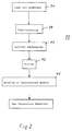
- Figure 4 depicts the steps of the process of the present invention in a flow chart form.
- a casting step 77 wet membrane is cast onto a reinforcing fiber.
- a winding step 79 the fiber reinforced wet membrane is wound into a spiral module.
- solvents replace water in the spiralwound module.
- Solvents are typically organic solvents.
- treatment solutions may be circulated to gel, anneal, repair or accomplish other changes to the particular membrane material used.
- a drying step 83 the solvents are evaporated to leave a dry membrane.
- Figure 5 depicts an apparatus for conducting solvent exchange and drying of the module.
- a spiral module 88 is placed in a container 90 having an inlet 92 and an outlet 94 for fluid.
- An O-ring, or U-cup 97 forms a seal between the module 88 and the container 90 so that any fluid passing from the container inlet 92 to the outlet 94 must pass through the spiral module 88.
- a circulating pump 99 transfers fluid from a reservoir 101 to the container inlet 92. Excess fluid exits the container 90 through the container outlet 94 and returns to the reservoir 101.
- the fluid pump 99 can be replaced with an air pump 103 and the container outlet 94 can be connected to a vacuum pump 105.
- the air pump 103 forces dry air into the container 90 and the vacuum pump 105 assists removal of air from the container through the container outlet 94.
- the vacuum pump 105 is optional.
- the reservoir 101 may contain multiple sections for storing different solvents.
- the reservoirs may be temperature controlled, for example, to provide a cold gelling solution, a hot annealing solution, or a cold exchange solvent.
- the reservoir may hold a treating solution of the same material used for casting the wet membranes, thereby repairing damaged membranes.
- a cellulose acetate cast solution made up of materials listed in the Table 1 was cast on a glass plate with a 2,54 ⁇ 10 ⁇ 2 cm (10 mill) doctor blade and allowed to gel for 10 to 15 minutes.
- the solution contains both organic and inorganic materials.
- CA Cellulose Acetate
- CDA Cellulose diacetate
- CTA Cellulose triacetate
- Dioxane 55 g Acetone 25 g Methanol 7 g
- the membrane was removed from the glass plate and annealed by emersion in 86° centigrade water. Annealed membrane was then immersed in isopropanol for 7 minutes, then in n-heptane for 7 minutes and then air dried at ambient room temperature. Polyester cloth was separately immersed in 86° centigrade water, immersed in isopropanol and n-heptane for 7 minutes each, and air dried in the same manner as the membrane. Shrinkage for both the membrane and the polyester cloth were measured and the results are tabulated in Table 2.
- membrane reinforced with polyester cloth would curl, especially during the drying step.
- the cellulose acetate solution of embodiment 1 was applied to polyester cloth with a 10 mill doctor blade, held for 5 to 10 second, then gelled in water at 1° centigrade for 5 to 15 minutes.
- the reinforced membrane was immersed in isopropanol at 3° centigrade for 7 minutes, then in n-heptane at 3° centigrade for 7 minutes.
- the reinforced membrane was fixed between two plates having a central hole so as to hold it around its periphery.
- a treating solution of 0.2% silicone and n-heptane was then poured onto the upper side of the reinforced membrane and a vacuum was applied to the lower side for 10 minutes. Application of the treating solution was stopped and vacuum held until the membrane dried completely. Gas permeation rates and selectivities of the dried membrane under 6,89 ⁇ 105 Pa (100 psi) pure gas were measured and the results tabulated in Table 3.
- a wet cast reinforced membrane identical to the one used in embodiment 2 was prepared in an identical manner, except that, soaking in isopropanol and n-heptane occurred at room temperature. Gas permeation rates and selectivities of the resultant dry membrane were measured and are tabulated in Table 4. The results revealed that the membrane exhibits good performance even though solvent exchange occurred at room temperature.
- the reinforced membrane was fixed between two plates having central holes so as to hold it around its periphery and dried at 30° centigrade, 50% relative humidity for 24 hours.
- a 0.5% silicone solution in n-heptane was poured on the dry membrane while applying the vacuum on the lower side for 1 minute. The solution was stopped and vacuum applied until the membrane dried completely. Gas permeation rates and selectivities were measured, and the results are tabulated in Table 6.
- the cast solution of embodiment 2 was cast on polyester cloth and held for 5 to 10 seconds.
- the reinforced membrane was then gelled at 1° centigrade for 5 to 15 minutes.
- the membrane was then heat annealed at 89° centigrade for 5 minutes, after which it was immersed in isopropanol at 3° centigrade for 7 minutes and n-heptane at 3° centigrade for 7 minutes.
- the membrane was air dried at ambient temperature, and observation showed severe curling as illustrated in Figures 5 and 6. Gas permeation rates and selectivities were measured and the results are tabulated in Table 7. This data reveals that cracking and curling causes lower selectivity.
- a 101.6 cm (40 inch) wide membrane was prepared by continuous type membrane coating and wound into a 10,16 cm by 101.6 cm (4 inch by 40 inch) spiral module.
- the module was placed in a container as shown in Figure 6. Isopropanol was circulated for 1 day, then n-heptane for 1 day, then a 0.1% silicone solution in n-heptane for 1 day. Excess solution was decanted from the container, and the module was purged with dry air from the container inlet while applying vacuum to the container outlet. Gas permeation rates and selectivities of the dried module were measured under 6,89 ⁇ 105 Pa (100 psi) pure gas, and the results are tabulated in Table 8.
- Two 2 inch by 12 inch annealed gas separation modules were prepared, one by drying before rolling and the other by rolling before drying.
- the selectivities of each membrane to nitrogen and oxygen were measured and the results shown in the first line (sample 1) of the Table 9.
- Two 5,08 cm by 30,48 cm (2 inch by 12 inch) unannealed membranes were similarly prepared, one by the drying before rolling and one by rolling before drying.
- the selectivities of the unannealed membranes to nitrogen and oxygen are shown in the second line (sample 2) of Table 9.
Landscapes
- Chemical & Material Sciences (AREA)
- Chemical Kinetics & Catalysis (AREA)
- Engineering & Computer Science (AREA)
- Analytical Chemistry (AREA)
- General Chemical & Material Sciences (AREA)
- Oil, Petroleum & Natural Gas (AREA)
- Inorganic Chemistry (AREA)
- Manufacturing & Machinery (AREA)
- Separation Using Semi-Permeable Membranes (AREA)
Abstract
Description
- The invention relates to a process for preparing gas separation membranes and modules. Gas separation membranes are films which exhibit a higher permeability toward some gases than toward others. Industries increasingly employ such membranes for such uses as: oxygen enrichment of air, purification of nitrogen, recovery of hydrogen from hydrogen reaction systems, removal of acid gases from natural gas or biogas, and separation of acid such as Co₂ from H₂S.
- Such membranes have no moving parts, negligible maintenance, low energy requirements, operational flexibility, and rapid start up and shut down. They may be formed as flat sheets, hollow fibers or tubes. A reinforcing fabric of woven or nonwoven polyester, or nylon increases membrane strength, improves operational properties and provides longer life.
- The rate at which gas permeates a membrane can be expressed as p/l, where p is the gas permeability, and l is the effective membrane thickness. Cellulose acetate exhibits particular commercial importance because its effective thickness is about 0.1 micrometers. This in turn, results in a relatively high gas permeation rate.
- Cloth reinforced membranes have been prepared by casting a cellulose acetate solution on the cloth and then gelling, leaching, annealing, solvent exchanging and drying the cloth/membrane combination. US-A-3 497 072 discloses a phase inversion technique for casting a cellulose acetate membrane. If a wet membrane is to be dried directly, the high surface tension of water will destroy the microporous structure. Drying methods which can prevent this destruction include first freeze drying; second adding an agent to reduce surface tension; and third exchanging the water solvent for another solvent. US-A-3 842 515 describes a solvent exchanging process which exchanges water with water missible alcohol, then exchanges the alcohol with a nonpolar organic solvent, and finally evaporates the nonpolar organic solvent to leave a dried membrane. US-A-4 080 743 describes a solvent exchanging process which first exchanges water with water missible organic solvents, and then evaporates the mixture to leave a dried membrane.
- During the step of drying, different shrinkage ratios between the cellulose acetate membrane and the reinforcing cloth causes curling, wrinkling and cracking. Moreover, brittle membranes sometimes crack during winding into spiral wound modules. US-A-4 134 742 discusses these problems and attempts to reduce curling by utilizing a reinforcing cloth having a shrinkage ratio close to that of the membrane. This approach does not solve problems caused by uneven shrinking between the membrane in the reinforcing cloth, nor does it reduce cracking problems when winding a dried membrane into spiral wound module.
- It is the primary object of the present invention to provide a novel and improved process for forming gas separation membranes and spiral wound gas separation modules avoids shrinking and curling by winding wet membrane onto a core before drying.
- The scope of the invention is defined in the appended claims. It is shown that the spiral wount wet membrane is placed in a treating container, and treating solutions for solvent exchange are circulated through the container and membrane. After solvent exchange, the spiral wound membrane is dried.
- In the following the invention is described more detailed in connection with the embodiments of the invention shown at the drawings.
-
- Figure 1 is a partially cut-away view of a spiral wound gas separation membrane;
- Figure 2 is a flow chart of steps in a former process for producing spiralwound gas separation membranes and modules;
- Figure 3 is a schematic representation of an apparatus using the process of Fig. 2;
- Figure 4 is a flow chart of steps in a process for producing spiralwound gas separation membranes and modules embodying the present invention; and
- Figure 5 is a schematic representation of an apparatus for treating and drying gas separation membrane modules in accordance with the present invention.
- The invention is a process for producing a gas separation membrane and module. Materials used for industrial gas separation membrane applications include cellulose acetate (CA), polysulfone, polyamide, polyimide, polycarbonate, polysiloxanes, poly (4-methyl-1-pentene), poly (phenylene oxide) and poly (vinylidene fluoride).
- Figure 1 shows an example of such a spiral wound
gas separation membrane 11 as disclosed in US-A-4 134 742. The module comprises amultilayer membrane sheet 13 wound onto ahollow core member 15 havingperforations 17. Themultilayer membrane sheet 13 consists of two layers of cloth reinforcedmembrane 19 separated by a layer oftricot netting 21. Each layer of reinforcedmembrane 19 is covered by an exterior layer ofvexar netting 23 on the opposite side of themembrane 19 from thetricot netting 21. In operation, a gas mixture is feed into theinput end 25 of the spiral woundmultilayer membrane sheet 13. The gas mixture spreads through thevexar netting 23, and the more permeable gas of the mixture penetrates the reinforcedmembrane 19 into thetricot netting layer 21. The tricot netting 21 conducts the selected gas spirally toperforations 17 of thehollow core member 15. The permeated gas then passes through theperforations 17 in thehollow core member 15 and can be removed through thepermeate output 27 of thehollow core member 15. Non-permeable gas of the gas mixtures passes through thevexar netting 23 and exits through theresidual output 29. - Figure 2 shows a
process 35 descriped in US-A 4 134 742 for producing a spiral wound gas separation membrane as shown in Figure 1. In a casting step 37 wet membrane is cast onto a reinforcing fiber. In apost-treating step 39, the wet membrane is treated by gelling (immersing in a cold liquid), annealing (immersing in a hot liquid), or other treatment. In asolvent exchange step 41, one or more solvents replaces water used in the cast material. In adrying step 43, the exchange solvent is dried from the membrane. In awinding step 45, the dried membrane is wound onto a core to produce a spiral wound module. - Figure 3 shows an apparatus for forming a spiral wound gas separation module using the traditional process of Figure 2. A
casting solution 51 is cast onto a reinforcingfiber 53 to form a reinforcedwet membrane 55. The reinforced wet membrane is immersed in agelling tank 57 which contains cold water. The gelled membrane is then immersed in anannealing tank 59 containing hot water. The annealed membrane is then immersed in one or moresolvent exchange tanks 61 which contain a series of exchange solvents. After solvent exchange, the membrane is dried in adrying apparatus 63. The driedmembrane 65 is then wound onto a core to form aspiral wound module 67. - Figure 4 depicts the steps of the process of the present invention in a flow chart form. In a
casting step 77 wet membrane is cast onto a reinforcing fiber. In awinding step 79 the fiber reinforced wet membrane is wound into a spiral module. In asolvent exchanging step 80 solvents replace water in the spiralwound module. Solvents are typically organic solvents. In a treatingstep 81, treatment solutions may be circulated to gel, anneal, repair or accomplish other changes to the particular membrane material used. In adrying step 83 the solvents are evaporated to leave a dry membrane. - Figure 5 depicts an apparatus for conducting solvent exchange and drying of the module. A
spiral module 88 is placed in acontainer 90 having aninlet 92 and anoutlet 94 for fluid. An O-ring, or U-cup 97 forms a seal between themodule 88 and thecontainer 90 so that any fluid passing from thecontainer inlet 92 to theoutlet 94 must pass through thespiral module 88. A circulatingpump 99 transfers fluid from areservoir 101 to thecontainer inlet 92. Excess fluid exits thecontainer 90 through thecontainer outlet 94 and returns to thereservoir 101. After completing solvent exchange, thefluid pump 99 can be replaced with anair pump 103 and thecontainer outlet 94 can be connected to avacuum pump 105. Theair pump 103 forces dry air into thecontainer 90 and thevacuum pump 105 assists removal of air from the container through thecontainer outlet 94. Thevacuum pump 105 is optional. Thereservoir 101 may contain multiple sections for storing different solvents. The reservoirs may be temperature controlled, for example, to provide a cold gelling solution, a hot annealing solution, or a cold exchange solvent. The reservoir may hold a treating solution of the same material used for casting the wet membranes, thereby repairing damaged membranes. The embodiments described below illustrate details of the present invention. - A cellulose acetate cast solution made up of materials listed in the Table 1 was cast on a glass plate with a 2,54·10⁻² cm (10 mill) doctor blade and allowed to gel for 10 to 15 minutes. The solution contains both organic and inorganic materials.
TABLE 1 Cellulose Acetate (CA) Cast Solution Composition Components Parts By Weight Cellulose diacetate (CDA) 8 g Cellulose triacetate (CTA) 8 g Dioxane 55 g Acetone 25 g Methanol 7 g Maleic acid 5 g Acetic acid 7 g - The membrane was removed from the glass plate and annealed by emersion in 86° centigrade water. Annealed membrane was then immersed in isopropanol for 7 minutes, then in n-heptane for 7 minutes and then air dried at ambient room temperature. Polyester cloth was separately immersed in 86° centigrade water, immersed in isopropanol and n-heptane for 7 minutes each, and air dried in the same manner as the membrane. Shrinkage for both the membrane and the polyester cloth were measured and the results are tabulated in Table 2.
TABLE 2 Shrinkage Ratios Treatment Length & Width (cm) Shrinkage Ratio (%) Unannealed wet membrane 8 - Annealed wet membrane 7.8 -2.5 Annealed dry membrane 7.65 -4.4 Unannealed dry membrane 7.57 -5.4 Unannealed polyester cloth 10 0 Annealed polyester cloth 10 0 Polyester cloth after solvent soaking, then drying 10 0 - Because of the high shrinkage difference between membrane and polyester cloth, membrane reinforced with polyester cloth would curl, especially during the drying step.
- The cellulose acetate solution of embodiment 1 was applied to polyester cloth with a 10 mill doctor blade, held for 5 to 10 second, then gelled in water at 1° centigrade for 5 to 15 minutes. The reinforced membrane was immersed in isopropanol at 3° centigrade for 7 minutes, then in n-heptane at 3° centigrade for 7 minutes. The reinforced membrane was fixed between two plates having a central hole so as to hold it around its periphery. A treating solution of 0.2% silicone and n-heptane was then poured onto the upper side of the reinforced membrane and a vacuum was applied to the lower side for 10 minutes. Application of the treating solution was stopped and vacuum held until the membrane dried completely. Gas permeation rates and selectivities of the dried membrane under 6,89·10⁵ Pa (100 psi) pure gas were measured and the results tabulated in Table 3.

- A wet cast reinforced membrane identical to the one used in embodiment 2 was prepared in an identical manner, except that, soaking in isopropanol and n-heptane occurred at room temperature. Gas permeation rates and selectivities of the resultant dry membrane were measured and are tabulated in Table 4.

The results revealed that the membrane exhibits good performance even though solvent exchange occurred at room temperature. - A cast solution made up of materials listed in Table 5 was cast on polyester cloth with a 2,54·10⁻² cm (10 mill) doctor blade, then gelled in 20° centigrade water for 10 to 20 minutes.
TABLE 5 Polysulfone Cast Solution Material Amount P-3500 35 g NMP (N-methyl pyrrolidone) 80 g THF (Tetrahydrofuran) 80 g PG (propylene glycol) 10 g - The reinforced membrane was fixed between two plates having central holes so as to hold it around its periphery and dried at 30° centigrade, 50% relative humidity for 24 hours. A 0.5% silicone solution in n-heptane was poured on the dry membrane while applying the vacuum on the lower side for 1 minute. The solution was stopped and vacuum applied until the membrane dried completely. Gas permeation rates and selectivities were measured, and the results are tabulated in Table 6.

- The cast solution of embodiment 2 was cast on polyester cloth and held for 5 to 10 seconds. The reinforced membrane was then gelled at 1° centigrade for 5 to 15 minutes. The membrane was then heat annealed at 89° centigrade for 5 minutes, after which it was immersed in isopropanol at 3° centigrade for 7 minutes and n-heptane at 3° centigrade for 7 minutes. The membrane was air dried at ambient temperature, and observation showed severe curling as illustrated in Figures 5 and 6. Gas permeation rates and selectivities were measured and the results are tabulated in Table 7.

This data reveals that cracking and curling causes lower selectivity. - A 101.6 cm (40 inch) wide membrane was prepared by continuous type membrane coating and wound into a 10,16 cm by 101.6 cm (4 inch by 40 inch) spiral module. The module was placed in a container as shown in Figure 6. Isopropanol was circulated for 1 day, then n-heptane for 1 day, then a 0.1% silicone solution in n-heptane for 1 day. Excess solution was decanted from the container, and the module was purged with dry air from the container inlet while applying vacuum to the container outlet. Gas permeation rates and selectivities of the dried module were measured under 6,89·10⁵ Pa (100 psi) pure gas, and the results are tabulated in Table 8.

- Two 2 inch by 12 inch annealed gas separation modules were prepared, one by drying before rolling and the other by rolling before drying. The selectivities of each membrane to nitrogen and oxygen were measured and the results shown in the first line (sample 1) of the Table 9. Two 5,08 cm by 30,48 cm (2 inch by 12 inch) unannealed membranes were similarly prepared, one by the drying before rolling and one by rolling before drying. The selectivities of the unannealed membranes to nitrogen and oxygen are shown in the second line (sample 2) of Table 9.

- It is to be realized that only preferred embodiments of the invention have been described and that numerous substitutions, modifications and alterations are permissible without departing from the invention as defined in the following claims.
Claims (20)
- A process for preparing gas modules containing a reinforced membrane, characterized in the steps of- Casting a membrane-forming material on an fibre cloth, then geling in cold water to form a porous wet membrane,- Winding the membrane into spiral module, whereby one side of the membrane is covered with a layer of polypropylene material which enables the transport of the gas to be separated through the spiral module, without passing through the membrane, and the other side of the membrane is covered with a layer of polyester material which leads the separated gas into the core member,- Mounting the module in a solvent exchange apparatus,- Circulating the solvent exchange solution throughout the solvent exchange apparatus also throughout the inside of module for an appropriate period of time to remove the water contained within the membrane, drain the exchange solution, then circulating the repair solution throughout the inside of module for an appropriate period of time,- Purging a gas throughout the module until the membrane is dried.
- A process according to claim 1, characterized in that the membrane-forming material comprises a combination of organic and inorganic materials.
- A process according to claim 1, characterized in that the organic membrane forming material comprises a natural macromolecule.
- A process according to claim 1, the organic membrane forming material comprises a synthetic polymer.
- A process according to claim 1, characterized in that the organic membrane-forming material comprises one of cellulose acetate, polysulfone, polyamide, polycarbonate, polysiloxane, poly(4-methyl-pentene), poly(phenylene oxide), and poly(vinylidene fluoride).
- A process according to claim 1, characterized in that the treating solution comprises a solution of the membrane forming material used for casting the membrane or the wet membrane.
- A process according to claim 1, characterized in that the treating solution comprises an organic solvent.
- A process according to claim 1, characterized in that the treating solution comprises silicone.
- A process according to claim 1, characterized in that the treating solution comprises one of n-heptane, isopropanol, and silicone.
- A process according to claim 1, characterized in that the period of circulation of the treating fluid is in the range of 1 minute to 48 hours.
- A process according to claim 10, characterized in that the period of circulation of the treating fluid is in the range of 1 hour to 24 hours.
- A process according to claim 10 or 11, characterized in that the period of circulation of the treating fluid is in the range of 11 hours to 13 hours.
- A process according to claim 1, characterized in that the membrane comprises a single layer of membrane material.
- A process according to claim 1, characterized in that the module comprises multiple layers of membrane material.
- A process according to claim 1, characterized in that the module is purged with air.
- A process according to claim 1, characterized in that the module is purged with inert gas.
- Solvent exchange apparatus for execution of the process according to claim 1 and 6 to 12, characterized in that the apparatus comprises a closed container (90) having a container inlet (92) and a container outlet (94), and a seal (97) disposed within the container (90) in such a manner that when the spiral module (88) is disposed within the container (90), fluid pumped into the inlet (92) passes through the module (88) to the outlet (94).
- Solvent exchange apparatus according to claim 17, characterized in that the container (90) is purged with air.
- Solvent exchange apparatus according to claim 17, characterized in that the container (90) is purged with inert gas.
- Solvent exchange apparatus according to claim 17, characterized in that the spiral module (88) is arranged in a unidirectional flow treating container (90).
Priority Applications (3)
| Application Number | Priority Date | Filing Date | Title |
|---|---|---|---|
| DE69015174T DE69015174T2 (en) | 1990-07-10 | 1990-07-10 | Membrane production for the separation of gases and spiral wound membrane module. |
| EP90113127A EP0465697B1 (en) | 1990-07-10 | 1990-07-10 | Preparation of gas separation membrane and spiral wound gas separation module |
| AT90113127T ATE115436T1 (en) | 1990-07-10 | 1990-07-10 | MEMBRANE MANUFACTURE FOR SEPARATION OF GASES AND SPIRAL WRAPPED MEMBRANE MODULE. |
Applications Claiming Priority (1)
| Application Number | Priority Date | Filing Date | Title |
|---|---|---|---|
| EP90113127A EP0465697B1 (en) | 1990-07-10 | 1990-07-10 | Preparation of gas separation membrane and spiral wound gas separation module |
Publications (2)
| Publication Number | Publication Date |
|---|---|
| EP0465697A1 EP0465697A1 (en) | 1992-01-15 |
| EP0465697B1 true EP0465697B1 (en) | 1994-12-14 |
Family
ID=8204197
Family Applications (1)
| Application Number | Title | Priority Date | Filing Date |
|---|---|---|---|
| EP90113127A Expired - Lifetime EP0465697B1 (en) | 1990-07-10 | 1990-07-10 | Preparation of gas separation membrane and spiral wound gas separation module |
Country Status (3)
| Country | Link |
|---|---|
| EP (1) | EP0465697B1 (en) |
| AT (1) | ATE115436T1 (en) |
| DE (1) | DE69015174T2 (en) |
Cited By (2)
| Publication number | Priority date | Publication date | Assignee | Title |
|---|---|---|---|---|
| WO2016014491A1 (en) * | 2014-07-21 | 2016-01-28 | Ohio State Innovation Foundation | Composite membranes for separation of gases |
| WO2016196474A1 (en) * | 2015-05-29 | 2016-12-08 | Ohio State Innovation Foundation | Polymeric membranes for separation of gases |
Families Citing this family (2)
| Publication number | Priority date | Publication date | Assignee | Title |
|---|---|---|---|---|
| DE10262009A1 (en) * | 2002-10-29 | 2004-05-19 | Daimlerchrysler Ag | Polymer electrolyte membrane fuel cell with a reinforced polymer electrolyte membrane |
| DE10250316A1 (en) * | 2002-10-29 | 2004-05-19 | Daimlerchrysler Ag | Reinforced polymer membrane, used as polymer electrolyte membrane in fuel cell or dialysis or separation membrane, has acid polymer and basic organic reinforcement layers adhering by electrostatic interaction |
Family Cites Families (5)
| Publication number | Priority date | Publication date | Assignee | Title |
|---|---|---|---|---|
| US3497072A (en) * | 1966-05-02 | 1970-02-24 | Aerojet General Co | Reverse osmosis membrane and method of manufacture |
| GB1256491A (en) * | 1967-09-12 | 1971-12-08 | ||
| CA923664A (en) * | 1968-05-03 | 1973-04-03 | D. Slowig Walter | Preparation of dry, stabilized, rewettable semipermeable membranes |
| JPS55327Y2 (en) * | 1974-12-18 | 1980-01-08 | ||
| US4430807A (en) * | 1982-05-17 | 1984-02-14 | The Dow Chemical Company | Process for drying water-wet membranes |
-
1990
- 1990-07-10 AT AT90113127T patent/ATE115436T1/en not_active IP Right Cessation
- 1990-07-10 EP EP90113127A patent/EP0465697B1/en not_active Expired - Lifetime
- 1990-07-10 DE DE69015174T patent/DE69015174T2/en not_active Expired - Fee Related
Cited By (3)
| Publication number | Priority date | Publication date | Assignee | Title |
|---|---|---|---|---|
| WO2016014491A1 (en) * | 2014-07-21 | 2016-01-28 | Ohio State Innovation Foundation | Composite membranes for separation of gases |
| US10322379B2 (en) | 2014-07-21 | 2019-06-18 | Ohio State Innovation Foundation | Composite membranes for separation of gases |
| WO2016196474A1 (en) * | 2015-05-29 | 2016-12-08 | Ohio State Innovation Foundation | Polymeric membranes for separation of gases |
Also Published As
| Publication number | Publication date |
|---|---|
| DE69015174T2 (en) | 1995-07-27 |
| ATE115436T1 (en) | 1994-12-15 |
| EP0465697A1 (en) | 1992-01-15 |
| DE69015174D1 (en) | 1995-01-26 |
Similar Documents
| Publication | Publication Date | Title |
|---|---|---|
| US4527999A (en) | Separation membrane and method of preparing and using same | |
| Lonsdale | Reverse Osmosis Membrane Research: Based on the Symposium on “Polymers for Desalination” Held at the 162nd National Meeting of the American Chemical Society in Washington, DC, September 1971 | |
| US4243701A (en) | Preparation of gas separation membranes | |
| US4681605A (en) | Anisotropic membranes for gas separation | |
| US4772391A (en) | Composite membrane for reverse osmosis | |
| US3852388A (en) | Preparation of asymmetric polymer membranes | |
| EP0286090B1 (en) | Improved composite separation membranes and the preparation and use thereof | |
| KR930003213B1 (en) | Permeable membrane for improved gas separation | |
| KR930012044B1 (en) | Tubesheets for Semi-Permeable Membrane Devices | |
| EA026762B1 (en) | Forward osmosis membrane | |
| JP2012503542A (en) | Asymmetric and composite separation membrane cast on tricot | |
| JPS5824304A (en) | Semipermeable composite membrane of high performance | |
| EP0125907A1 (en) | Separation of dewaxing solvent from dewaxed oil in a lube oil dewaxing process using asymmetric polyimide membranes | |
| US10010833B2 (en) | Spiral wound membrane module with reinforced fold line | |
| US5236643A (en) | Preparation of gas separation membrane and spiral wound gas separation module | |
| KR101969915B1 (en) | Method of preparing ceramic composite membrane and the ceramic composite membrane thereby | |
| JPS6268504A (en) | Supported membrane and method of manufacturing the same | |
| US4659590A (en) | Pervaporation separation of ethanol-water mixtures using polyethylenimine composite membranes | |
| US5049169A (en) | Polysulfone separation membrane | |
| EP0338074B1 (en) | Treatment of permeable membranes | |
| EP0465697A1 (en) | Preparation of gas separation membrane and spiral wound gas separation module | |
| US3873653A (en) | Preparation of high flux cellulose acetate membranes and hollow fibers from prefabricated low flux specimens | |
| EP0311912A1 (en) | Multilayer reverse osmosis membrane in which one layer is poly-meta-phenylene tetrahydrofuran-2,3,4,5-tetracarboxamide | |
| KR920007858B1 (en) | Improved Synthetic Membranes and Their Preparation and Uses | |
| JP3588886B2 (en) | Method and apparatus for producing composite reverse osmosis membrane |
Legal Events
| Date | Code | Title | Description |
|---|---|---|---|
| PUAI | Public reference made under article 153(3) epc to a published international application that has entered the european phase |
Free format text: ORIGINAL CODE: 0009012 |
|
| AK | Designated contracting states |
Kind code of ref document: A1 Designated state(s): AT BE CH DE DK ES FR GB GR IT LI LU NL SE |
|
| 17P | Request for examination filed |
Effective date: 19920615 |
|
| 17Q | First examination report despatched |
Effective date: 19921113 |
|
| GRAA | (expected) grant |
Free format text: ORIGINAL CODE: 0009210 |
|
| AK | Designated contracting states |
Kind code of ref document: B1 Designated state(s): AT BE CH DE DK ES FR GB GR IT LI LU NL SE |
|
| PG25 | Lapsed in a contracting state [announced via postgrant information from national office to epo] |
Ref country code: NL Effective date: 19941214 Ref country code: LI Effective date: 19941214 Ref country code: GR Free format text: LAPSE BECAUSE OF FAILURE TO SUBMIT A TRANSLATION OF THE DESCRIPTION OR TO PAY THE FEE WITHIN THE PRESCRIBED TIME-LIMIT Effective date: 19941214 Ref country code: ES Free format text: THE PATENT HAS BEEN ANNULLED BY A DECISION OF A NATIONAL AUTHORITY Effective date: 19941214 Ref country code: DK Effective date: 19941214 Ref country code: CH Effective date: 19941214 Ref country code: BE Effective date: 19941214 Ref country code: AT Effective date: 19941214 |
|
| REF | Corresponds to: |
Ref document number: 115436 Country of ref document: AT Date of ref document: 19941215 Kind code of ref document: T |
|
| REF | Corresponds to: |
Ref document number: 69015174 Country of ref document: DE Date of ref document: 19950126 |
|
| ET | Fr: translation filed | ||
| ITF | It: translation for a ep patent filed | ||
| PG25 | Lapsed in a contracting state [announced via postgrant information from national office to epo] |
Ref country code: SE Effective date: 19950314 |
|
| REG | Reference to a national code |
Ref country code: CH Ref legal event code: PL |
|
| NLV1 | Nl: lapsed or annulled due to failure to fulfill the requirements of art. 29p and 29m of the patents act | ||
| PG25 | Lapsed in a contracting state [announced via postgrant information from national office to epo] |
Ref country code: LU Free format text: LAPSE BECAUSE OF NON-PAYMENT OF DUE FEES Effective date: 19950731 |
|
| PLBE | No opposition filed within time limit |
Free format text: ORIGINAL CODE: 0009261 |
|
| STAA | Information on the status of an ep patent application or granted ep patent |
Free format text: STATUS: NO OPPOSITION FILED WITHIN TIME LIMIT |
|
| 26N | No opposition filed | ||
| PGFP | Annual fee paid to national office [announced via postgrant information from national office to epo] |
Ref country code: FR Payment date: 19980724 Year of fee payment: 9 |
|
| PG25 | Lapsed in a contracting state [announced via postgrant information from national office to epo] |
Ref country code: FR Free format text: THE PATENT HAS BEEN ANNULLED BY A DECISION OF A NATIONAL AUTHORITY Effective date: 19990731 |
|
| REG | Reference to a national code |
Ref country code: FR Ref legal event code: ST |
|
| PGFP | Annual fee paid to national office [announced via postgrant information from national office to epo] |
Ref country code: DE Payment date: 20010619 Year of fee payment: 12 |
|
| PGFP | Annual fee paid to national office [announced via postgrant information from national office to epo] |
Ref country code: GB Payment date: 20010626 Year of fee payment: 12 |
|
| REG | Reference to a national code |
Ref country code: GB Ref legal event code: IF02 |
|
| PG25 | Lapsed in a contracting state [announced via postgrant information from national office to epo] |
Ref country code: GB Free format text: LAPSE BECAUSE OF NON-PAYMENT OF DUE FEES Effective date: 20020710 |
|
| PG25 | Lapsed in a contracting state [announced via postgrant information from national office to epo] |
Ref country code: DE Free format text: LAPSE BECAUSE OF NON-PAYMENT OF DUE FEES Effective date: 20030201 |
|
| GBPC | Gb: european patent ceased through non-payment of renewal fee |
Effective date: 20020710 |
|
| PG25 | Lapsed in a contracting state [announced via postgrant information from national office to epo] |
Ref country code: IT Free format text: LAPSE BECAUSE OF NON-PAYMENT OF DUE FEES;WARNING: LAPSES OF ITALIAN PATENTS WITH EFFECTIVE DATE BEFORE 2007 MAY HAVE OCCURRED AT ANY TIME BEFORE 2007. THE CORRECT EFFECTIVE DATE MAY BE DIFFERENT FROM THE ONE RECORDED. Effective date: 20050710 |