EP0465300A1 - Verfahren zur Regelung der Sendeleistung von Endstationen in einem Zeitgetrenntlage-Übertragungsnetzwerk - Google Patents
Verfahren zur Regelung der Sendeleistung von Endstationen in einem Zeitgetrenntlage-Übertragungsnetzwerk Download PDFInfo
- Publication number
- EP0465300A1 EP0465300A1 EP91401715A EP91401715A EP0465300A1 EP 0465300 A1 EP0465300 A1 EP 0465300A1 EP 91401715 A EP91401715 A EP 91401715A EP 91401715 A EP91401715 A EP 91401715A EP 0465300 A1 EP0465300 A1 EP 0465300A1
- Authority
- EP
- European Patent Office
- Prior art keywords
- level
- terminal
- transmission
- station
- central station
- Prior art date
- Legal status (The legal status is an assumption and is not a legal conclusion. Google has not performed a legal analysis and makes no representation as to the accuracy of the status listed.)
- Granted
Links
Images


Classifications
-
- H—ELECTRICITY
- H04—ELECTRIC COMMUNICATION TECHNIQUE
- H04L—TRANSMISSION OF DIGITAL INFORMATION, e.g. TELEGRAPHIC COMMUNICATION
- H04L12/00—Data switching networks
- H04L12/28—Data switching networks characterised by path configuration, e.g. LAN [Local Area Networks] or WAN [Wide Area Networks]
- H04L12/44—Star or tree networks
-
- H—ELECTRICITY
- H04—ELECTRIC COMMUNICATION TECHNIQUE
- H04L—TRANSMISSION OF DIGITAL INFORMATION, e.g. TELEGRAPHIC COMMUNICATION
- H04L5/00—Arrangements affording multiple use of the transmission path
- H04L5/14—Two-way operation using the same type of signal, i.e. duplex
- H04L5/1469—Two-way operation using the same type of signal, i.e. duplex using time-sharing
- H04L5/1484—Two-way operation using the same type of signal, i.e. duplex using time-sharing operating bytewise
- H04L5/1492—Two-way operation using the same type of signal, i.e. duplex using time-sharing operating bytewise with time compression, e.g. operating according to the ping-pong technique
Definitions
- the present invention relates to the transmission level adjustment in terminal stations located at the ends of a half-duplex alternating communication network, also of the tree-type and fiber-optic type.
- the operation of a tree-to -ternate network poses another problem relating to the adaptation of the power of the transmitter in each terminal station as a function of the distance from this terminal station to the central station. Indeed, the signals coming from terminal stations at different distances are received with very different levels in the receiver of the central station, due to the different attenuations due to the different cable lengths and to the numbers of couplers respectively crossed by the signals. If no precautions are taken, the receiver must have a high dynamic range in order to adapt to each time interval of the return frame at the transmission level of the terminal station to which this interval is assigned.
- the present invention aims to remedy this adaptation of the transmission level, so that the receiver of the central station receives signals having the same level, whatever the distances from the terminal stations to the central station.
- Control of the emission level in each terminal station is programmed from the central station, which automates the commissioning of each terminal station.
- the transmission level of each terminal station can then be readjusted during the high duration of the terminal station, by predetermined period.
- the transmission of the amplitude reference word developed from the level indicated by the modification orders is provided in the interval between a return frame and a forward frame, which avoids any disturbance of these on the reference word.
- a modification of the transmission level consists in incrementing and decrementing an account in response respectively to orders of incrementation and of decrementation elaborated by the central station, in making correspond to the account a numerical value of amplitude, and decrementing a down counter from said amplitude value to define an integration time for an integrator providing an amplitude level corresponding to a transmitter of the terminal.
- circuits for signal processing in central and terminal stations are in digital form, it advantageously appears that the means provided by the present invention with regard to comparisons and order processing in the central station, and the increments and decrementations analogous to a digital-analog conversion in each terminal station, can also be carried out in the form of easily integrated digital circuits.
- a change of programmable PROM memory in the terminal stations allows adaptability of the terminal stations to the transmission characteristics of the network, such as bit rate, alternation period and frame.
- the invention contributes to preserving the quality of the transmission of the signals in the network, by monitoring preventively and automatically the terminal stations by the central station connected to a maintenance center.
- the components, in particular the electro-optical components for a fiber optic network, in the terminal stations are dependent on the respective surrounding conditions, such as temperature and humidity and therefore have operations subject to variation over time. Periodically, the level control controlled by the central station will "compensate" for the aging of the components.
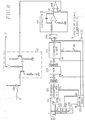
- FIG. 1 An alternating fiber optic communication network having a tree architecture, as shown in FIG. 1.
- This network includes a central station 1 and a plurality K of terminal stations 21 to 2 K.
- the station central unit 1 is a telephone exchange serving several networks such as that shown in FIG. 1, and connected to the general telephone switched network.
- Each terminal station can be a simple telephone installation, or a more complex telephone installation, comprising a local network serving a plurality of specific terminals, such as telephone set, fax machine, videotex terminal, etc.
- the second stations 21 to 2 K will be hereinafter referred to as terminals.
- the network connecting the central station 1 to the terminals 21 to 2 K is composed of a tree whose trunk leaves from the central station and whose branches are divided in two at the level of bidirectional couplers 3 having a common access oriented towards the central station and several secondary accesses oriented towards terminals.
- the terminals 21 to 2 K are located at different distances from the central station.
- a first coupler 31 is located at a distance L0 from the central station 1 along an optical fiber of tree trunk FO, and is connected via respective secondary accesses in particular to the first terminal 21 by a length of optical fiber L1, and at the terminal 2 K by a length of optical fiber L K through at least two couplers 32 to 3 K.
- the other ports of the 32 and 3 K couplers serve other terminals, in this case the 2 k to 2 K-1 terminals.
- the terminal 21 is connected to the central station by a length of optical fiber L0 + L1 and a single coupler 31, while the terminal 2 K is connected to the central station through a length of optical fiber L0 + L K to through at least three couplers 31, 32 and 3 K.
- This disparity in the distances between central station and terminals introduces into the exchanged signals not only different propagation delay times but also different signal attenuations.
- the means to remedy the disparity in the propagation delays do not belong to the framework of the present invention, and the reader will refer to this subject to the French patent application FR-A-2636482 already cited.
- the nominal amplitude level is designated by NO for suitable reception in the central station 1, it appears, according to the respective locations of the terminals 21 and 2 K according to FIG. 1, that the power of the transmitter of terminal 21, closest to station 1, must be less than that of terminal 2 K , that is: N0 / A1 ⁇ NO / A K
- the exchanges of signals between the central station and the various terminals are transmitted in a so-called collective alternation and multiple access time division (TDMA) mode.
- This transmission mode allows a dialogue between the central station and the terminals through a single medium, in this case an optical fiber, according to the two directions of transmission.
- TDMA collective alternation and multiple access time division
- a first direction of transmission called forward direction, or sometimes downward direction, from the central station 1 to the terminals 21 to 2 K , the central station 1 processes and transmits signals to the terminals respectively in the form of a forward frame T12 .
- each of the terminals transmits signals to the attention of the central station by inserting them in respective well-determined time intervals of return frames T21.
- each frame T12, T21 must be less than 250 ⁇ s in length to take account of the forward propagation time / maximum return between station 1 and the most distant terminal, ie a TP time which also includes a guard time necessary for switching from transmission mode to reception mode in each of the stations, central station and terminal.
- a frame is composed of a GES management field and K sectors reserved for subscriber terminals.
- a given rank sector is not assigned once and for all to a terminal, but is dedicated to a terminal according to the availability of other sectors.
- the IT2 sector of rank 2 can be assigned to the terminal 2 K-1 of rank K-1.
- This allocation of multiplexed time intervals IT1 to IT K forming the sectors is determined by the central station 1 as a function of the distance between this station and the requesting terminal, according to a process analogous to that described in the aforementioned French patent application.
- Each sector is intended to convey information proper between the requesting terminal and another remote terminal through the central station 1.
- the GES management field is composed of a frame locking word MVT, a terminal address, called a J token, a control word MC, control information IC, and other management bits. outside the scope of the present invention and designated by AG.
- the frame locking word MVT is intended, in a conventional manner, to synchronize the time bases included in the subscriber terminals 21 to 2 K , playing the role of slave, on the clock included in the central station 1 , playing the role of master station.
- each terminal recovers the bit clock HB, here equal to 4.096 MHz.
- the token J is constituted by the number 1 to K of the terminal 21 to 2 K for which the MC and IC information which follows in the management field are intended.
- K 8
- the token J consists of a 3-bit word.
- a subscriber terminal To avoid any error, i.e. in particular to prevent an already synchronized terminal from responding to the central station following an error in the transmission of the token, a subscriber terminal must detect its number as a token in two successive forward frames to deduce therefrom that the information MC and IC particularly for a transmission of the word MVT concern it.
- the MC field consists of different control orders coded according to an exchange protocol between the central station and the terminals. These orders may relate to the commissioning of a terminal, that is to say on the one hand the allocation to this terminal of an available sector IT1 to IT K , and on the other hand a procedure for the adjustment progressive amplitude level of the terminal transmitter, as will be seen below.
- the control orders can also relate to periodic monitoring of the terminals, with a view to regulating their level of transmission amplitude as a function of the aging of the components internal to the terminals, and, of course, can relate to all requests for incoming or outgoing communication. departure between the central station and each terminal, and therefore the allocation of an IT1 to IT K information sector dedicated to this terminal.
- the IC field contains values associated with the control orders included in the MC field, for example a numerical value associated with a summation ordered by a coded word included in the MC field.
- This additional management information serves many functions, and is all expressed in digital form.
- the frame T21 has a structure similar to the frame T12, and includes a management field as well as K sectors allocated to the terminals. For the same communication relating to a terminal, the two sectors which are allocated to it have the same rank in the frames T12 and T21.
- the management field in the return frame does not include a locking word, and all the fields J, MC and IC relating to a terminal in the process of protocol exchange with the central station has a variable position in the GES field, which depends on the distance from this terminal to the central station.
- the field IC is composed of a reference word of amplitude MRA constituted by a determined number N of bits in the state "1" which constitutes analog information enabling the central station to deduce therefrom the power level to which the terminal's transmission circuit is adjusted, by comparing the amplitude of each bit with the state "1" of the word MRA received at predetermined thresholds NF, NI, NS.
- NF, NI, NS predetermined thresholds
- the terminal when the terminal has detected its number as a token J in a frame T12, then in the next field MC a command to transmit the word MRA, ie at a time t D , the terminal waits during a second phase up to a time t A corresponding to the reception of the rest of the forward frame T12 at this terminal, to transmit the word MRA with an initial level INI to the central station 1.
- the central station During the propagation time TP, the central station only receives and identifies a single MRA word from the terminal during amplitude adjustment. Of course, this assumes that the other terminals in service are already set in time.
- the central station After analysis of the amplitude of bits "1" of the word MRA received, the central station sends, always with the address J of the terminal, an order to modify the transmission level (MC + IC [UD]) to the terminal in question . Then in a fourth phase, the terminal retransmits the amplitude reference word MRA having a new amplitude modified according to the commands ordered by the central station.
- Cycles comprising the last forward transmission phase and the last return transmission phase are iterated until the effective adjustment of the amplitude of the terminal transmitter to the nominal level N0 received in station 1.
- the number of adjustment cycles is counted in the central station, and if this exceeds a predetermined number, the terminal is declared "out of order".
- the central station performs a cyclical scan of the terminals in order to periodically adjust the level of amplitude of transmission of the terminals, which varies according to the aging and thermal drifts of the components included in each terminal, and in general of the terminal environment.
- the principle of adjusting the amplitude level in a terminal is as follows, with reference to FIG. 5.
- a third level is defined as significantly lower than the nominal level N0, this third level NF being typically equal to 0.1 N0.
- the increment or decrement is done step by step, a step being for example equal to 0.01 NO.
- the incrementation will be carried out by jumps of 8 steps between two adjustment cycles.
- the initial level INI of the signals transmitted by a terminal to be connected to the tree network is typically between NI and NF, so that for a terminal to be connected near the central station, the adjustment is made very quickly, while for a terminal to be connected at a relatively large distance from the central station, the adjustment is carried out in several cycles.
- the central station 1 conventionally comprises, on the tree network side, an optical coupler with three accesses, coupling an optical fiber terminating FO of the tree trunk of the network to a photoreceptor, of the PIN photodiode type, and to a photo- LED diode or laser diode emitter through short intermediate optical fibers FR and FA.
- the PIN diode is connected to a reception and amplification circuit 13 transmitting the return frames T21 to a demultiplexing circuit 14 included in a time channel switching unit UCO of the central station 1.
- the switching unit UCO comprises at the output a multiplexing circuit 15 for periodically forming the forward frames T12, and in particular for packetizing the data proper intended respectively for terminals in the form of 96-bit sectors, and for entering information into the GES management field.
- the T12 frames are transmitted in series to a transmission circuit 16 relating to the amplification and the polarization of the LED diode.
- the central station 1 comprises a circuit for analyzing the word MRA and for developing the amplitude adjustment order UD, 17.
- the circuit 17 comprises three voltage comparators 171S, 171I and 171F, three shift registers 172S, 172I and 172F, three OR gates 173S, 173I and 173F, a logic encoder 174 and a register control circuit 175.
- the comparators 171S, 171I and 171F receive respectively at the first reverse, direct and direct inputs the reference voltage levels NS, NI and NF. Second direct, inverse and inverse inputs respectively of the comparators 171S, 171I and 171F receive the signal SR recovered by the reception circuit 13 and conveying the return frames T21. A logic signal at the output of one of these three comparators is in state "1" when the voltage at the direct input (+) of the comparator is higher than the voltage at the reverse input (-) of this same comparator.
- the outputs of the three comparators 171S, 171I and 171F are connected respectively to the inputs of the shift registers 172S, 172I and 172F each having a number of one-bit stages equal to N-1.
- OR gates 173S, 173I and 173F have N-1 inputs respectively connected to the outputs of registers 172S, 172I and 172F and outputs connected to respective inputs 174S, 174I and 174F of encoder 174.
- the output of the three OR gates 173S, 173I and 173F is in the state "0", and two outputs U and D of encoder 174 are also in the "0" state.
- the "analog" level of the signal SR can be understood only in four predetermined voltage ranges so that the result of the comparisons is coded only on two bits U and D.
- the register control circuit 175 detects the start of an amplitude reference word MRA so that the bit levels of this word are successively quantized and recorded in the shift registers.
- Circuit 175 essentially comprises an OR gate with two inputs 1751, an RS flip-flop 1752, a modulo N counter 1753 and an AND gate with two inputs 1754.
- An inverse input of gate 1751 is connected to the output of the third comparator 171F, while that a direct input from gate 1751 receives an end of propagation time IF pulse, substantially preceding the start of the forward frame T12 and produced by a time base BT in the switching unit UCO.
- the flip-flop 1752 has a setting input at "1" S connected to the output of door 1751, an output Q connected to an input of door 1754 and to a counting input CO of the counter 1753, and a setting input. "0" R connected to an output of the 1753 counter.
- the second input of gate 1754 and a clock input CL of the 1753 counter receive the clock signal HB at the frequency of 4.096 Mbit / s of the time base BT.
- the output of gate 1754 is connected to the clock inputs CL of the three shift registers 172S, 172I, 172F.
- the shift registers are reset to zero by their input R in response to the rising edge of the clock signal at the alternation of period TA (FIG. 2), preceding the reception of a return frame T21.
- TA period of period
- the output of gate 1751 changes to the state "1" which triggers the counting of clock pulses in the counter 1753 and "l 'sampling' of the comparator outputs and therefore the offset of the different samples obtained in the shift registers, at the clock frequency HB.
- the preceding operations are stopped as soon as the counter 1753 has counted N clock pulses, which resets the flip-flop 1752, and consequently closes the AND gate 1754.
- the level of bits "1" of the amplitude reference word MRA is between NI and NS and is therefore correct. If at least one of, or more of the stages of register 172S, respectively of register 172I, are in state "1", the level of the signal received SR is too high and it is therefore necessary to decrease the amplitude of the signal transmitted in terminal 2, respectively is too weak and it is necessary to increase the amplitude of the signal transmitted in terminal 2.
- the level of the signal received SR is much too low, since it is lower than the level NF, and the amplitude of the signal transmitted in terminal 2 must be increased very quickly, for example with 8 steps each time, until reaching a level corresponding to a reception level in station 1 greater than NF.
- the pulse IF at the end of the window TP during which normally the word MRA must be received sets itself to "1" the flip-flop 1752, and consequently authorizes by default the counting of N pulses clock by the 1753 counter as well as the offsets in registers 172S, 172I and 172F.
- the number of stages in the shift register can be chosen lower than N for example N-2, N-3, etc.
- the number of stages in these registers is chosen all the greater as the detection of the word MRA is precise.
- the number N-1 of stages per register is preferably chosen so that the sampling of the results of the comparisons takes into account the slope of the rising edge of the first bit of the word received MRA and the response time of the comparators.
- the encoder 174 comprises for example an AND gate 1741 with two inputs, two AND doors with three inputs 1742 and 1743 and an OR gate with two inputs 1744 so that the outputs U and D of the doors 1741 and 1744 are in the respective states according to the previous table.
- the output of the OR gate 173S at the output of the register 172S is connected to an inverse input of the gate 1741, to a direct input of the gate 1742 and to a first inverse input of the gate 1743.
- the output of the gate OR 173I in output of the shift register 1721 is connected to a direct input of the gate 1741, to a first reverse input of the gate 1742 and to a first direct input of the gate 1743.
- the output of the OR gate 173F at the output of the shift register 172F is connected to a second reverse input of door 1742 and to a second direct input of door 1743.
- the outputs of doors 1742 and 1743 are connected to the respective inputs of OR gate 1744.
- the two bits U and D are then stored in a buffer memory included in the multiplexing circuit 15, and are inserted in the control information field IC of a forward frame T12, following a control word MC inviting the terminal in question to adjust the amplitude in question 2, the address of which is contained in the token J of the frame T12.
- a terminal 2 comprises, on the tree network side, a three-port optical coupler 20 coupling a respective optical fiber fo of the tree network to a reception circuit 21 with PIN diode and to a transmission circuit 22 with LED diode through two intermediate optical fibers fa and Fr.
- the terminal further comprises a UT data processing unit in which a demultiplexing circuit 23 is connected to the output of the reception circuit 21, and a multiplexing circuit 24 serves the input of the transmission circuit 22.
- a demultiplexing circuit 23 is connected to the output of the reception circuit 21, and a multiplexing circuit 24 serves the input of the transmission circuit 22.
- the invention also provides an intermediate circuit between the reception means 21-23 and the transmission means 24-22, said amplitude adjustment circuit 25.
- the demultiplexing circuit 23 is associated with a time base 231 which recovers the frame and bit frequencies from the frame alignment word MVT contained in the header of the forward frames T12, and means for detecting in the field of GES management, the terminal number as token J.
- the demultiplexing circuit 23 recognizes an amplitude adjustment word in the MC field, the two bits U and D contained in the IC field are applied to the inputs of the amplitude adjustment circuit 25.
- the multiplexing circuit also supplies the internal circuits of the terminal with the actual data allocated to it and inserted in the IT sector dedicated to the terminal.
- the amplitude adjustment circuit 25 essentially comprises an 8-bit up-down counter 252, a pluggable PROM linearization memory 253, a 10-bit down-counter 254, an RS 255 flip-flop and an integrator 256.
- the sizes of the counter- down counter, PROM memory and down counter are given only as an example.
- a counting authorization input EU of the counter 252 receives the bit U directly, while a countdown entry ED of the up-down counter 252 receives the bit D through a NAND gate 257 and an AND gate 258. Both inputs of gate 257 receive bits U and D. One input of gate 258 receives bit D while the other input of this gate is connected to the output of gate 257.
- the inputs EU and UD are in the state "0", and the count of the up-down counter 252 is not modified.
- the bits U and D delivered by the demultiplexing circuit 23 are also combined with inputs E1 and E8 of the time base 231 through an OR-Exclusive gate 232 and another AND gate with two inputs 233.
- the time base 231 applies only one clock pulse to a clock input CL of the up-down counter 252 of so as to increase or decrease by a step typically equal to (0.01 NO), the amplitude of the signal to be transmitted by the terminal.
- the time base 231 When the output of the AND gate 233 connected to the input E8 is in the state "1", the time base 231 briefly applies a determined number of clock pulses, for example eight, to the input of CL clock of the up-down counter 252 so that the amplitude of the signal to be transmitted by the circuit 22 is increased rapidly.
- the programmable read-only memory 253 is addressed in reading by 8-bit addresses supplied by the up-down counter 252, and makes the digital value of an amplitude correspond to each address. Thus the memory 253 performs the "digital-analog" conversion between a coded amplitude and the actual value of the amplitude. Initially, when the terminal 2 is switched on, the counter 252 is at zero, which corresponds, as already said, to an initial minimum amplitude MIN comprised substantially between the levels NS and NI.
- the digital amplitude value is read from memory 253, in the form of a 10-bit word which is loaded into the down-counter 254, and the output Q of the flip-flop 255 connected at the input of the integrator 256 is set to "1".
- the down-counter 254 receives clock pulses at the frequency 2 x FM where x is typically equal to 10.
- the holding output B of the down-counter 254 is connected to the input R of the flip-flop 255.
- the flip-flop 25 is set to zero.
- the integrator 256 thus converts the digital value of the amplitude into an analog voltage.
- This analog voltage VS is applied to the transmission circuit 22 through an amplifier-follower 259.
- An modulation input of the transmission circuit 22 receives the digital signals to be transmitted to the central station 1, established by the multiplexing circuit 24.
- the resistance and capacitance values in the integrator 256 are suitably sized.
- a word MRA "11 ... 1" can be produced by the demultiplexer 24 under the control of the time base 231, at the start of the TP window, after reception of the T12 frame.
Applications Claiming Priority (2)
| Application Number | Priority Date | Filing Date | Title |
|---|---|---|---|
| FR9008211 | 1990-06-29 | ||
| FR9008211A FR2664112B1 (fr) | 1990-06-29 | 1990-06-29 | Procede de reglage de niveau d'emission de terminaux dans un reseau de transmission a l'alternat. |
Publications (2)
| Publication Number | Publication Date |
|---|---|
| EP0465300A1 true EP0465300A1 (de) | 1992-01-08 |
| EP0465300B1 EP0465300B1 (de) | 1995-09-13 |
Family
ID=9398147
Family Applications (1)
| Application Number | Title | Priority Date | Filing Date |
|---|---|---|---|
| EP19910401715 Expired - Lifetime EP0465300B1 (de) | 1990-06-29 | 1991-06-26 | Verfahren zur Regelung der Sendeleistung von Endstationen in einem Zeitgetrenntlage-Übertragungsnetzwerk |
Country Status (3)
| Country | Link |
|---|---|
| EP (1) | EP0465300B1 (de) |
| DE (1) | DE69112927T2 (de) |
| FR (1) | FR2664112B1 (de) |
Cited By (1)
| Publication number | Priority date | Publication date | Assignee | Title |
|---|---|---|---|---|
| US5272694A (en) * | 1991-03-21 | 1993-12-21 | France Telecom | Synchronization of terminal stations in a multirate half-duplex tree-structured network |
Citations (3)
| Publication number | Priority date | Publication date | Assignee | Title |
|---|---|---|---|---|
| EP0049670A1 (de) * | 1980-10-08 | 1982-04-14 | Gérard Pays | Einrichtung zum Minimieren des Fernnebensprechens zwischen Leitungen mit digitaler Übertragung in zeitgetrennter Lage |
| WO1984004638A1 (en) * | 1983-05-12 | 1984-11-22 | American Telephone & Telegraph | Communication network |
| WO1988009093A1 (en) * | 1987-05-06 | 1988-11-17 | British Telecommunications Public Limited Company | Control of optical systems |
-
1990
- 1990-06-29 FR FR9008211A patent/FR2664112B1/fr not_active Expired - Fee Related
-
1991
- 1991-06-26 EP EP19910401715 patent/EP0465300B1/de not_active Expired - Lifetime
- 1991-06-26 DE DE1991612927 patent/DE69112927T2/de not_active Expired - Lifetime
Patent Citations (3)
| Publication number | Priority date | Publication date | Assignee | Title |
|---|---|---|---|---|
| EP0049670A1 (de) * | 1980-10-08 | 1982-04-14 | Gérard Pays | Einrichtung zum Minimieren des Fernnebensprechens zwischen Leitungen mit digitaler Übertragung in zeitgetrennter Lage |
| WO1984004638A1 (en) * | 1983-05-12 | 1984-11-22 | American Telephone & Telegraph | Communication network |
| WO1988009093A1 (en) * | 1987-05-06 | 1988-11-17 | British Telecommunications Public Limited Company | Control of optical systems |
Non-Patent Citations (1)
| Title |
|---|
| ELECTRONIC LETTERS vol. 23, no. 19, Novembre 1987, ENAGE, GB pages 1255 - 1257; STERN ET AL.: 'Passive optical local networks for telephony applications and beyond. ' * |
Cited By (1)
| Publication number | Priority date | Publication date | Assignee | Title |
|---|---|---|---|---|
| US5272694A (en) * | 1991-03-21 | 1993-12-21 | France Telecom | Synchronization of terminal stations in a multirate half-duplex tree-structured network |
Also Published As
| Publication number | Publication date |
|---|---|
| FR2664112A1 (fr) | 1992-01-03 |
| DE69112927D1 (de) | 1995-10-19 |
| FR2664112B1 (fr) | 1993-05-28 |
| EP0465300B1 (de) | 1995-09-13 |
| DE69112927T2 (de) | 1996-05-15 |
Similar Documents
| Publication | Publication Date | Title |
|---|---|---|
| EP0555596B1 (de) | Verfahren zur Bestimmung der Laufzeit zwischen einer entfernten Endstation und einer zentralen Endstation, in einem bidirektionalen Punkt-zu-Mehrpunkt-Übertragungssystem | |
| CA2557425C (en) | Apparatus and method for compensating for data degardation | |
| FR2533094A1 (fr) | Methode de controle d'un systeme de transmission numerique, systeme et repeteurs appliquant cette methode | |
| EP0027413B1 (de) | Übertragungssystem mit gleichzeitigem integralen Vielfachzugriff über optische Fiberübertragungsleitungen | |
| EP0505281B1 (de) | Endstationssynchronisierung in einem Baumnetzwerk mit mehreren Übertragungsraten und Halbduplexbetrieb | |
| EP0053958A1 (de) | Verfahren zur Parallel-Serien-Umsetzung einer digitalen, parallelen Folge | |
| CA2138107C (en) | Method and device for the fine synchronization of atm cells in optical atm nodes | |
| EP0933895A1 (de) | Verfahren zur Detektion eines or mehrerer freien Kanäle in einem optischen Multiplexsignal, eine Vorrichtung zur Ausführung und eine Anwendung der Vorrichtung | |
| EP0108692A1 (de) | Verfahren und Einrichtung zur Übertragung von digitalen Daten | |
| EP0027410A1 (de) | Verfahren zur Vermittlung von Zeitmultiplex-Signalen, die durch eine Trägerwelle übertragen werden, insbesondere eine optische Welle, und Vorrichtung zur Durchführung | |
| EP0064923B1 (de) | System zur Phasensynchronisation digitaler Datenströme und seine Verwendung bei der Umschaltung der Datenströme | |
| EP0465300B1 (de) | Verfahren zur Regelung der Sendeleistung von Endstationen in einem Zeitgetrenntlage-Übertragungsnetzwerk | |
| FR2597689A1 (fr) | Dispositif pour la recuperation de rythme convenant notamment pour un systeme de transmission d'informations utilisant dans un sens de transmission le principe dit d'a.m.r.t. | |
| EP0843931B1 (de) | Übertragungsverfahren über einen optischen bus mit gleichzeitig verschiedenen datenraten | |
| EP1592159A2 (de) | Optisches Übertragungsnetz mit Baumstruktur | |
| CA3122373C (fr) | Procede d'etablissement de communication dans un reseau d'acces optique | |
| EP0555595B1 (de) | Verfahren zur Zeitschlitzenzuweisung in einem Zeitmultiplex-Vielfachzugriffübertragungssystem | |
| FR2606240A1 (fr) | Emetteur-recepteur pour verification de liaisons de transmission et appareil le comportant | |
| FR2636482A1 (fr) | Procede de synchronisation pour le multiplexage de mots dans un reseau de communication etoile a fibres optiques | |
| FR2665992A1 (fr) | Procede de reception de signaux multiplexes en longueur d'onde, notamment pour la surveillance des lignes de transport d'energie. | |
| EP0384847A1 (de) | Verfahren und Vorrichtung zum Zugriff auf ein erweitertes Netz | |
| CA3176135C (fr) | Procede d'etablissement de communication dans un reseau d'acces optique | |
| EP0509434B1 (de) | Übertragungsanlage mit fernüberwachter optischer Verbindung | |
| JPH03140025A (ja) | 光空間通信方式 | |
| EP0443482A1 (de) | Anordnung zum Anschluss digitaler Endstationen an eine einzige Schnittstelle höherer Geschwindigkeit |
Legal Events
| Date | Code | Title | Description |
|---|---|---|---|
| PUAI | Public reference made under article 153(3) epc to a published international application that has entered the european phase |
Free format text: ORIGINAL CODE: 0009012 |
|
| AK | Designated contracting states |
Kind code of ref document: A1 Designated state(s): DE FR GB |
|
| 17P | Request for examination filed |
Effective date: 19911206 |
|
| 17Q | First examination report despatched |
Effective date: 19940418 |
|
| GRAA | (expected) grant |
Free format text: ORIGINAL CODE: 0009210 |
|
| AK | Designated contracting states |
Kind code of ref document: B1 Designated state(s): DE FR GB |
|
| GBT | Gb: translation of ep patent filed (gb section 77(6)(a)/1977) |
Effective date: 19950919 |
|
| REF | Corresponds to: |
Ref document number: 69112927 Country of ref document: DE Date of ref document: 19951019 |
|
| PLBE | No opposition filed within time limit |
Free format text: ORIGINAL CODE: 0009261 |
|
| STAA | Information on the status of an ep patent application or granted ep patent |
Free format text: STATUS: NO OPPOSITION FILED WITHIN TIME LIMIT |
|
| 26N | No opposition filed | ||
| REG | Reference to a national code |
Ref country code: GB Ref legal event code: IF02 |
|
| PGFP | Annual fee paid to national office [announced via postgrant information from national office to epo] |
Ref country code: GB Payment date: 20100527 Year of fee payment: 20 Ref country code: FR Payment date: 20100729 Year of fee payment: 20 Ref country code: DE Payment date: 20100610 Year of fee payment: 20 |
|
| REG | Reference to a national code |
Ref country code: DE Ref legal event code: R071 Ref document number: 69112927 Country of ref document: DE |
|
| REG | Reference to a national code |
Ref country code: DE Ref legal event code: R071 Ref document number: 69112927 Country of ref document: DE |
|
| REG | Reference to a national code |
Ref country code: GB Ref legal event code: PE20 Expiry date: 20110625 |
|
| PG25 | Lapsed in a contracting state [announced via postgrant information from national office to epo] |
Ref country code: GB Free format text: LAPSE BECAUSE OF EXPIRATION OF PROTECTION Effective date: 20110625 |
|
| PG25 | Lapsed in a contracting state [announced via postgrant information from national office to epo] |
Ref country code: DE Free format text: LAPSE BECAUSE OF EXPIRATION OF PROTECTION Effective date: 20110627 |