EP0465300A1 - Method for controlling the transmission level of terminal stations in a time-sharing communications network - Google Patents
Method for controlling the transmission level of terminal stations in a time-sharing communications network Download PDFInfo
- Publication number
- EP0465300A1 EP0465300A1 EP91401715A EP91401715A EP0465300A1 EP 0465300 A1 EP0465300 A1 EP 0465300A1 EP 91401715 A EP91401715 A EP 91401715A EP 91401715 A EP91401715 A EP 91401715A EP 0465300 A1 EP0465300 A1 EP 0465300A1
- Authority
- EP
- European Patent Office
- Prior art keywords
- level
- terminal
- transmission
- station
- central station
- Prior art date
- Legal status (The legal status is an assumption and is not a legal conclusion. Google has not performed a legal analysis and makes no representation as to the accuracy of the status listed.)
- Granted
Links
Images


Classifications
-
- H—ELECTRICITY
- H04—ELECTRIC COMMUNICATION TECHNIQUE
- H04L—TRANSMISSION OF DIGITAL INFORMATION, e.g. TELEGRAPHIC COMMUNICATION
- H04L12/00—Data switching networks
- H04L12/28—Data switching networks characterised by path configuration, e.g. LAN [Local Area Networks] or WAN [Wide Area Networks]
- H04L12/44—Star or tree networks
-
- H—ELECTRICITY
- H04—ELECTRIC COMMUNICATION TECHNIQUE
- H04L—TRANSMISSION OF DIGITAL INFORMATION, e.g. TELEGRAPHIC COMMUNICATION
- H04L5/00—Arrangements affording multiple use of the transmission path
- H04L5/14—Two-way operation using the same type of signal, i.e. duplex
- H04L5/1469—Two-way operation using the same type of signal, i.e. duplex using time-sharing
- H04L5/1484—Two-way operation using the same type of signal, i.e. duplex using time-sharing operating bytewise
- H04L5/1492—Two-way operation using the same type of signal, i.e. duplex using time-sharing operating bytewise with time compression, e.g. operating according to the ping-pong technique
Definitions
- the present invention relates to the transmission level adjustment in terminal stations located at the ends of a half-duplex alternating communication network, also of the tree-type and fiber-optic type.
- the operation of a tree-to -ternate network poses another problem relating to the adaptation of the power of the transmitter in each terminal station as a function of the distance from this terminal station to the central station. Indeed, the signals coming from terminal stations at different distances are received with very different levels in the receiver of the central station, due to the different attenuations due to the different cable lengths and to the numbers of couplers respectively crossed by the signals. If no precautions are taken, the receiver must have a high dynamic range in order to adapt to each time interval of the return frame at the transmission level of the terminal station to which this interval is assigned.
- the present invention aims to remedy this adaptation of the transmission level, so that the receiver of the central station receives signals having the same level, whatever the distances from the terminal stations to the central station.
- Control of the emission level in each terminal station is programmed from the central station, which automates the commissioning of each terminal station.
- the transmission level of each terminal station can then be readjusted during the high duration of the terminal station, by predetermined period.
- the transmission of the amplitude reference word developed from the level indicated by the modification orders is provided in the interval between a return frame and a forward frame, which avoids any disturbance of these on the reference word.
- a modification of the transmission level consists in incrementing and decrementing an account in response respectively to orders of incrementation and of decrementation elaborated by the central station, in making correspond to the account a numerical value of amplitude, and decrementing a down counter from said amplitude value to define an integration time for an integrator providing an amplitude level corresponding to a transmitter of the terminal.
- circuits for signal processing in central and terminal stations are in digital form, it advantageously appears that the means provided by the present invention with regard to comparisons and order processing in the central station, and the increments and decrementations analogous to a digital-analog conversion in each terminal station, can also be carried out in the form of easily integrated digital circuits.
- a change of programmable PROM memory in the terminal stations allows adaptability of the terminal stations to the transmission characteristics of the network, such as bit rate, alternation period and frame.
- the invention contributes to preserving the quality of the transmission of the signals in the network, by monitoring preventively and automatically the terminal stations by the central station connected to a maintenance center.
- the components, in particular the electro-optical components for a fiber optic network, in the terminal stations are dependent on the respective surrounding conditions, such as temperature and humidity and therefore have operations subject to variation over time. Periodically, the level control controlled by the central station will "compensate" for the aging of the components.
- FIG. 1 An alternating fiber optic communication network having a tree architecture, as shown in FIG. 1.
- This network includes a central station 1 and a plurality K of terminal stations 21 to 2 K.
- the station central unit 1 is a telephone exchange serving several networks such as that shown in FIG. 1, and connected to the general telephone switched network.
- Each terminal station can be a simple telephone installation, or a more complex telephone installation, comprising a local network serving a plurality of specific terminals, such as telephone set, fax machine, videotex terminal, etc.
- the second stations 21 to 2 K will be hereinafter referred to as terminals.
- the network connecting the central station 1 to the terminals 21 to 2 K is composed of a tree whose trunk leaves from the central station and whose branches are divided in two at the level of bidirectional couplers 3 having a common access oriented towards the central station and several secondary accesses oriented towards terminals.
- the terminals 21 to 2 K are located at different distances from the central station.
- a first coupler 31 is located at a distance L0 from the central station 1 along an optical fiber of tree trunk FO, and is connected via respective secondary accesses in particular to the first terminal 21 by a length of optical fiber L1, and at the terminal 2 K by a length of optical fiber L K through at least two couplers 32 to 3 K.
- the other ports of the 32 and 3 K couplers serve other terminals, in this case the 2 k to 2 K-1 terminals.
- the terminal 21 is connected to the central station by a length of optical fiber L0 + L1 and a single coupler 31, while the terminal 2 K is connected to the central station through a length of optical fiber L0 + L K to through at least three couplers 31, 32 and 3 K.
- This disparity in the distances between central station and terminals introduces into the exchanged signals not only different propagation delay times but also different signal attenuations.
- the means to remedy the disparity in the propagation delays do not belong to the framework of the present invention, and the reader will refer to this subject to the French patent application FR-A-2636482 already cited.
- the nominal amplitude level is designated by NO for suitable reception in the central station 1, it appears, according to the respective locations of the terminals 21 and 2 K according to FIG. 1, that the power of the transmitter of terminal 21, closest to station 1, must be less than that of terminal 2 K , that is: N0 / A1 ⁇ NO / A K
- the exchanges of signals between the central station and the various terminals are transmitted in a so-called collective alternation and multiple access time division (TDMA) mode.
- This transmission mode allows a dialogue between the central station and the terminals through a single medium, in this case an optical fiber, according to the two directions of transmission.
- TDMA collective alternation and multiple access time division
- a first direction of transmission called forward direction, or sometimes downward direction, from the central station 1 to the terminals 21 to 2 K , the central station 1 processes and transmits signals to the terminals respectively in the form of a forward frame T12 .
- each of the terminals transmits signals to the attention of the central station by inserting them in respective well-determined time intervals of return frames T21.
- each frame T12, T21 must be less than 250 ⁇ s in length to take account of the forward propagation time / maximum return between station 1 and the most distant terminal, ie a TP time which also includes a guard time necessary for switching from transmission mode to reception mode in each of the stations, central station and terminal.
- a frame is composed of a GES management field and K sectors reserved for subscriber terminals.
- a given rank sector is not assigned once and for all to a terminal, but is dedicated to a terminal according to the availability of other sectors.
- the IT2 sector of rank 2 can be assigned to the terminal 2 K-1 of rank K-1.
- This allocation of multiplexed time intervals IT1 to IT K forming the sectors is determined by the central station 1 as a function of the distance between this station and the requesting terminal, according to a process analogous to that described in the aforementioned French patent application.
- Each sector is intended to convey information proper between the requesting terminal and another remote terminal through the central station 1.
- the GES management field is composed of a frame locking word MVT, a terminal address, called a J token, a control word MC, control information IC, and other management bits. outside the scope of the present invention and designated by AG.
- the frame locking word MVT is intended, in a conventional manner, to synchronize the time bases included in the subscriber terminals 21 to 2 K , playing the role of slave, on the clock included in the central station 1 , playing the role of master station.
- each terminal recovers the bit clock HB, here equal to 4.096 MHz.
- the token J is constituted by the number 1 to K of the terminal 21 to 2 K for which the MC and IC information which follows in the management field are intended.
- K 8
- the token J consists of a 3-bit word.
- a subscriber terminal To avoid any error, i.e. in particular to prevent an already synchronized terminal from responding to the central station following an error in the transmission of the token, a subscriber terminal must detect its number as a token in two successive forward frames to deduce therefrom that the information MC and IC particularly for a transmission of the word MVT concern it.
- the MC field consists of different control orders coded according to an exchange protocol between the central station and the terminals. These orders may relate to the commissioning of a terminal, that is to say on the one hand the allocation to this terminal of an available sector IT1 to IT K , and on the other hand a procedure for the adjustment progressive amplitude level of the terminal transmitter, as will be seen below.
- the control orders can also relate to periodic monitoring of the terminals, with a view to regulating their level of transmission amplitude as a function of the aging of the components internal to the terminals, and, of course, can relate to all requests for incoming or outgoing communication. departure between the central station and each terminal, and therefore the allocation of an IT1 to IT K information sector dedicated to this terminal.
- the IC field contains values associated with the control orders included in the MC field, for example a numerical value associated with a summation ordered by a coded word included in the MC field.
- This additional management information serves many functions, and is all expressed in digital form.
- the frame T21 has a structure similar to the frame T12, and includes a management field as well as K sectors allocated to the terminals. For the same communication relating to a terminal, the two sectors which are allocated to it have the same rank in the frames T12 and T21.
- the management field in the return frame does not include a locking word, and all the fields J, MC and IC relating to a terminal in the process of protocol exchange with the central station has a variable position in the GES field, which depends on the distance from this terminal to the central station.
- the field IC is composed of a reference word of amplitude MRA constituted by a determined number N of bits in the state "1" which constitutes analog information enabling the central station to deduce therefrom the power level to which the terminal's transmission circuit is adjusted, by comparing the amplitude of each bit with the state "1" of the word MRA received at predetermined thresholds NF, NI, NS.
- NF, NI, NS predetermined thresholds
- the terminal when the terminal has detected its number as a token J in a frame T12, then in the next field MC a command to transmit the word MRA, ie at a time t D , the terminal waits during a second phase up to a time t A corresponding to the reception of the rest of the forward frame T12 at this terminal, to transmit the word MRA with an initial level INI to the central station 1.
- the central station During the propagation time TP, the central station only receives and identifies a single MRA word from the terminal during amplitude adjustment. Of course, this assumes that the other terminals in service are already set in time.
- the central station After analysis of the amplitude of bits "1" of the word MRA received, the central station sends, always with the address J of the terminal, an order to modify the transmission level (MC + IC [UD]) to the terminal in question . Then in a fourth phase, the terminal retransmits the amplitude reference word MRA having a new amplitude modified according to the commands ordered by the central station.
- Cycles comprising the last forward transmission phase and the last return transmission phase are iterated until the effective adjustment of the amplitude of the terminal transmitter to the nominal level N0 received in station 1.
- the number of adjustment cycles is counted in the central station, and if this exceeds a predetermined number, the terminal is declared "out of order".
- the central station performs a cyclical scan of the terminals in order to periodically adjust the level of amplitude of transmission of the terminals, which varies according to the aging and thermal drifts of the components included in each terminal, and in general of the terminal environment.
- the principle of adjusting the amplitude level in a terminal is as follows, with reference to FIG. 5.
- a third level is defined as significantly lower than the nominal level N0, this third level NF being typically equal to 0.1 N0.
- the increment or decrement is done step by step, a step being for example equal to 0.01 NO.
- the incrementation will be carried out by jumps of 8 steps between two adjustment cycles.
- the initial level INI of the signals transmitted by a terminal to be connected to the tree network is typically between NI and NF, so that for a terminal to be connected near the central station, the adjustment is made very quickly, while for a terminal to be connected at a relatively large distance from the central station, the adjustment is carried out in several cycles.
- the central station 1 conventionally comprises, on the tree network side, an optical coupler with three accesses, coupling an optical fiber terminating FO of the tree trunk of the network to a photoreceptor, of the PIN photodiode type, and to a photo- LED diode or laser diode emitter through short intermediate optical fibers FR and FA.
- the PIN diode is connected to a reception and amplification circuit 13 transmitting the return frames T21 to a demultiplexing circuit 14 included in a time channel switching unit UCO of the central station 1.
- the switching unit UCO comprises at the output a multiplexing circuit 15 for periodically forming the forward frames T12, and in particular for packetizing the data proper intended respectively for terminals in the form of 96-bit sectors, and for entering information into the GES management field.
- the T12 frames are transmitted in series to a transmission circuit 16 relating to the amplification and the polarization of the LED diode.
- the central station 1 comprises a circuit for analyzing the word MRA and for developing the amplitude adjustment order UD, 17.
- the circuit 17 comprises three voltage comparators 171S, 171I and 171F, three shift registers 172S, 172I and 172F, three OR gates 173S, 173I and 173F, a logic encoder 174 and a register control circuit 175.
- the comparators 171S, 171I and 171F receive respectively at the first reverse, direct and direct inputs the reference voltage levels NS, NI and NF. Second direct, inverse and inverse inputs respectively of the comparators 171S, 171I and 171F receive the signal SR recovered by the reception circuit 13 and conveying the return frames T21. A logic signal at the output of one of these three comparators is in state "1" when the voltage at the direct input (+) of the comparator is higher than the voltage at the reverse input (-) of this same comparator.
- the outputs of the three comparators 171S, 171I and 171F are connected respectively to the inputs of the shift registers 172S, 172I and 172F each having a number of one-bit stages equal to N-1.
- OR gates 173S, 173I and 173F have N-1 inputs respectively connected to the outputs of registers 172S, 172I and 172F and outputs connected to respective inputs 174S, 174I and 174F of encoder 174.
- the output of the three OR gates 173S, 173I and 173F is in the state "0", and two outputs U and D of encoder 174 are also in the "0" state.
- the "analog" level of the signal SR can be understood only in four predetermined voltage ranges so that the result of the comparisons is coded only on two bits U and D.
- the register control circuit 175 detects the start of an amplitude reference word MRA so that the bit levels of this word are successively quantized and recorded in the shift registers.
- Circuit 175 essentially comprises an OR gate with two inputs 1751, an RS flip-flop 1752, a modulo N counter 1753 and an AND gate with two inputs 1754.
- An inverse input of gate 1751 is connected to the output of the third comparator 171F, while that a direct input from gate 1751 receives an end of propagation time IF pulse, substantially preceding the start of the forward frame T12 and produced by a time base BT in the switching unit UCO.
- the flip-flop 1752 has a setting input at "1" S connected to the output of door 1751, an output Q connected to an input of door 1754 and to a counting input CO of the counter 1753, and a setting input. "0" R connected to an output of the 1753 counter.
- the second input of gate 1754 and a clock input CL of the 1753 counter receive the clock signal HB at the frequency of 4.096 Mbit / s of the time base BT.
- the output of gate 1754 is connected to the clock inputs CL of the three shift registers 172S, 172I, 172F.
- the shift registers are reset to zero by their input R in response to the rising edge of the clock signal at the alternation of period TA (FIG. 2), preceding the reception of a return frame T21.
- TA period of period
- the output of gate 1751 changes to the state "1" which triggers the counting of clock pulses in the counter 1753 and "l 'sampling' of the comparator outputs and therefore the offset of the different samples obtained in the shift registers, at the clock frequency HB.
- the preceding operations are stopped as soon as the counter 1753 has counted N clock pulses, which resets the flip-flop 1752, and consequently closes the AND gate 1754.
- the level of bits "1" of the amplitude reference word MRA is between NI and NS and is therefore correct. If at least one of, or more of the stages of register 172S, respectively of register 172I, are in state "1", the level of the signal received SR is too high and it is therefore necessary to decrease the amplitude of the signal transmitted in terminal 2, respectively is too weak and it is necessary to increase the amplitude of the signal transmitted in terminal 2.
- the level of the signal received SR is much too low, since it is lower than the level NF, and the amplitude of the signal transmitted in terminal 2 must be increased very quickly, for example with 8 steps each time, until reaching a level corresponding to a reception level in station 1 greater than NF.
- the pulse IF at the end of the window TP during which normally the word MRA must be received sets itself to "1" the flip-flop 1752, and consequently authorizes by default the counting of N pulses clock by the 1753 counter as well as the offsets in registers 172S, 172I and 172F.
- the number of stages in the shift register can be chosen lower than N for example N-2, N-3, etc.
- the number of stages in these registers is chosen all the greater as the detection of the word MRA is precise.
- the number N-1 of stages per register is preferably chosen so that the sampling of the results of the comparisons takes into account the slope of the rising edge of the first bit of the word received MRA and the response time of the comparators.
- the encoder 174 comprises for example an AND gate 1741 with two inputs, two AND doors with three inputs 1742 and 1743 and an OR gate with two inputs 1744 so that the outputs U and D of the doors 1741 and 1744 are in the respective states according to the previous table.
- the output of the OR gate 173S at the output of the register 172S is connected to an inverse input of the gate 1741, to a direct input of the gate 1742 and to a first inverse input of the gate 1743.
- the output of the gate OR 173I in output of the shift register 1721 is connected to a direct input of the gate 1741, to a first reverse input of the gate 1742 and to a first direct input of the gate 1743.
- the output of the OR gate 173F at the output of the shift register 172F is connected to a second reverse input of door 1742 and to a second direct input of door 1743.
- the outputs of doors 1742 and 1743 are connected to the respective inputs of OR gate 1744.
- the two bits U and D are then stored in a buffer memory included in the multiplexing circuit 15, and are inserted in the control information field IC of a forward frame T12, following a control word MC inviting the terminal in question to adjust the amplitude in question 2, the address of which is contained in the token J of the frame T12.
- a terminal 2 comprises, on the tree network side, a three-port optical coupler 20 coupling a respective optical fiber fo of the tree network to a reception circuit 21 with PIN diode and to a transmission circuit 22 with LED diode through two intermediate optical fibers fa and Fr.
- the terminal further comprises a UT data processing unit in which a demultiplexing circuit 23 is connected to the output of the reception circuit 21, and a multiplexing circuit 24 serves the input of the transmission circuit 22.
- a demultiplexing circuit 23 is connected to the output of the reception circuit 21, and a multiplexing circuit 24 serves the input of the transmission circuit 22.
- the invention also provides an intermediate circuit between the reception means 21-23 and the transmission means 24-22, said amplitude adjustment circuit 25.
- the demultiplexing circuit 23 is associated with a time base 231 which recovers the frame and bit frequencies from the frame alignment word MVT contained in the header of the forward frames T12, and means for detecting in the field of GES management, the terminal number as token J.
- the demultiplexing circuit 23 recognizes an amplitude adjustment word in the MC field, the two bits U and D contained in the IC field are applied to the inputs of the amplitude adjustment circuit 25.
- the multiplexing circuit also supplies the internal circuits of the terminal with the actual data allocated to it and inserted in the IT sector dedicated to the terminal.
- the amplitude adjustment circuit 25 essentially comprises an 8-bit up-down counter 252, a pluggable PROM linearization memory 253, a 10-bit down-counter 254, an RS 255 flip-flop and an integrator 256.
- the sizes of the counter- down counter, PROM memory and down counter are given only as an example.
- a counting authorization input EU of the counter 252 receives the bit U directly, while a countdown entry ED of the up-down counter 252 receives the bit D through a NAND gate 257 and an AND gate 258. Both inputs of gate 257 receive bits U and D. One input of gate 258 receives bit D while the other input of this gate is connected to the output of gate 257.
- the inputs EU and UD are in the state "0", and the count of the up-down counter 252 is not modified.
- the bits U and D delivered by the demultiplexing circuit 23 are also combined with inputs E1 and E8 of the time base 231 through an OR-Exclusive gate 232 and another AND gate with two inputs 233.
- the time base 231 applies only one clock pulse to a clock input CL of the up-down counter 252 of so as to increase or decrease by a step typically equal to (0.01 NO), the amplitude of the signal to be transmitted by the terminal.
- the time base 231 When the output of the AND gate 233 connected to the input E8 is in the state "1", the time base 231 briefly applies a determined number of clock pulses, for example eight, to the input of CL clock of the up-down counter 252 so that the amplitude of the signal to be transmitted by the circuit 22 is increased rapidly.
- the programmable read-only memory 253 is addressed in reading by 8-bit addresses supplied by the up-down counter 252, and makes the digital value of an amplitude correspond to each address. Thus the memory 253 performs the "digital-analog" conversion between a coded amplitude and the actual value of the amplitude. Initially, when the terminal 2 is switched on, the counter 252 is at zero, which corresponds, as already said, to an initial minimum amplitude MIN comprised substantially between the levels NS and NI.
- the digital amplitude value is read from memory 253, in the form of a 10-bit word which is loaded into the down-counter 254, and the output Q of the flip-flop 255 connected at the input of the integrator 256 is set to "1".
- the down-counter 254 receives clock pulses at the frequency 2 x FM where x is typically equal to 10.
- the holding output B of the down-counter 254 is connected to the input R of the flip-flop 255.
- the flip-flop 25 is set to zero.
- the integrator 256 thus converts the digital value of the amplitude into an analog voltage.
- This analog voltage VS is applied to the transmission circuit 22 through an amplifier-follower 259.
- An modulation input of the transmission circuit 22 receives the digital signals to be transmitted to the central station 1, established by the multiplexing circuit 24.
- the resistance and capacitance values in the integrator 256 are suitably sized.
- a word MRA "11 ... 1" can be produced by the demultiplexer 24 under the control of the time base 231, at the start of the TP window, after reception of the T12 frame.
Abstract
Description
La présente invention concerne le réglage de niveau d'émission dans des stations terminales situées aux extrémités d'un réseau de communication à l'alternat dit également semi-duplex, du type notamment arborescent et à fibre optique.The present invention relates to the transmission level adjustment in terminal stations located at the ends of a half-duplex alternating communication network, also of the tree-type and fiber-optic type.
Dans un tel réseau de communication, entre une station centrale faisant office de noeud de commutation et les stations terminales faisant office d'installations d'abonné sont échangées alternativement des trames respectivement suivant les deux sens de transmission.In such a communication network, between a central station acting as a switching node and the terminal stations acting as subscriber installations are alternately exchanged frames respectively in the two directions of transmission.
La constitution de ces trames et particulièrement les problèmes de synchronisation des moyens d'émission dans les stations terminales qui sont situées à des distances différentes de la station centrale, afin d'assigner sans chevauchement des intervalles temporels aux stations terminales dans une trame retour dirigée vers la station centrale, ont été exposés et résolus dans la demande de brevet français FR-A-2636482 déposée le 13 Septembre 1988.The constitution of these frames and particularly the problems of synchronization of the transmission means in the terminal stations which are located at different distances from the central station, in order to assign without overlapping time intervals to the terminal stations in a return frame directed towards the central station, were exposed and resolved in the French patent application FR-A-2636482 filed on September 13, 1988.
L'exploitation d'un réseau arborescent à l'alternat pose un autre problème relatif à l'adaptation de la puissance de l'émetteur dans chaque station terminale en fonction de la distance de cette station terminale à la station centrale. En effet, les signaux provenant de stations terminales à différentes distances sont reçus avec des niveaux très différents dans le récepteur de la station centrale, en raison des atténuations différentes dues aux diverses longueurs de câble et aux nombres de coupleurs respectivement traversés par les signaux. Si aucune précaution n'est prise, le récepteur doit présenter une dynamique élevée afin de s'adapter à chaque intervalle de temps de la trame retour au niveau d'émission de la station terminale auquel est assigné cet intervalle.The operation of a tree-to -ternate network poses another problem relating to the adaptation of the power of the transmitter in each terminal station as a function of the distance from this terminal station to the central station. Indeed, the signals coming from terminal stations at different distances are received with very different levels in the receiver of the central station, due to the different attenuations due to the different cable lengths and to the numbers of couplers respectively crossed by the signals. If no precautions are taken, the receiver must have a high dynamic range in order to adapt to each time interval of the return frame at the transmission level of the terminal station to which this interval is assigned.
La présente invention vise à remédier à cette adaptation de niveau d'émission, afin que le récepteur de la station centrale reçoive des signaux ayant un même niveau, quelles que soient les distances des stations terminales à la station centrale. Le pilotage du niveau d'émission dans chaque station terminale est programmé à partir de la station centrale, ce qui permet d'automatiser la mise en service de chaque station terminale. En outre, le niveau d'émission de chaque station terminale peut être ensuite réajusté au cours de la durée élevée de la station terminale, par période prédéterminée.The present invention aims to remedy this adaptation of the transmission level, so that the receiver of the central station receives signals having the same level, whatever the distances from the terminal stations to the central station. Control of the emission level in each terminal station is programmed from the central station, which automates the commissioning of each terminal station. Furthermore, the transmission level of each terminal station can then be readjusted during the high duration of the terminal station, by predetermined period.
A cette fin, un procédé pour régler le niveau d'émission de stations terminales situées à des distances différentes d'une station centrale à travers un réseau de communication à l'alternat dans lequel, à chaque période d'alternat est transmise une trame numérique aller de la station centrale vers les stations terminales, puis une trame retour des stations terminales vers la station centrale, la réception du début d'une trame retour par la station centrale succédant à l'émission de la fin d'une trame aller après un temps de programmation prédéterminé, est caractérisé par les étapes suivantes :
- émission d'une adresse de station terminale avec une commande de transmission relatif à un mot de référence d'amplitude, située en en-tête d'une trame aller par la station centrale,
- en réponse à l'adresse par une station terminale correspondante, émission du mot de référence d'amplitude avec un niveau d'émission initial juste après la réception de la fin de trame aller par la station terminale,
- comparaison du mot de référence à des seuils prédéterminés dans la station centrale, et si le résultat de la comparaison n'est pas satisfaisant, effectuer les deux étapes suivantes :
- émission de l'adresse de la station terminale avec un ordre de modification de niveau d'émission de la station terminale, située en en-tête d'une trame aller suivante par la station centrale, et
- en réponse à l'adresse par une station terminale correspondante, émission du mot de référence d'amplitude ayant un niveau d'émission modifié selon ledit ordre de modification juste après la réception de la trame aller suivante par la station terminale,
et répétitions du cycle comprenant lesdites comparaisons, émission avec ordre de modification de niveau et émission ayant un niveau modifié, tant qu'une comparaison n'est pas satisfaite si les répétitions sont inférieures à un nombre prédéterminé.
- transmission of a terminal station address with a transmission command relating to an amplitude reference word, located at the header of a forward frame by the central station,
- in response to the address by a corresponding terminal station, transmission of the amplitude reference word with an initial transmission level just after the reception of the outgoing frame end by the terminal station,
- comparison of the reference word with predetermined thresholds in the central station, and if the result of the comparison is not satisfactory, carry out the following two steps:
- transmission of the address of the terminal station with an order to modify the transmission level of the terminal station, located at the header of a next outgoing frame by the central station, and
- in response to the address by a corresponding terminal station, transmission of the amplitude reference word having a transmission level modified according to said modification order just after the reception of the next outgoing frame by the terminal station,
and repetitions of the cycle comprising said comparisons, transmission with level change order and transmission having a modified level, as long as a comparison is not satisfied if the repetitions are less than a predetermined number.
La transmission du mot de référence d'amplitude élaboré à partir du niveau indiqué par les ordres de modification, est prévue dans l'intervalle entre une trame retour et une trame aller, ce qui évite toutes perturbations de celles-ci sur le mot de référence.The transmission of the amplitude reference word developed from the level indicated by the modification orders is provided in the interval between a return frame and a forward frame, which avoids any disturbance of these on the reference word.
Dans la station centrale, une comparaison consiste, selon l'invention,
- à comparer le niveau de chaque bits à l'état logique "1" du mot de référence d'amplitude reçu dans la station centrale avec des seuils prédéterminés inférieur et supérieur,
- à déclarer la comparaison satisfaisante si un nombre prédéterminé de bits"1" ont des niveaux compris entre lesdits deux seuils prédéterminés,
- à élaborer un premier ordre d'incrémentation du niveau d'émission de la station terminale lorsque l'un des bits "1" du mot de référence est plus petit que ledit niveau inférieur, et
- à élaborer un ordre de décrémentation du niveau d'émission de la station terminale lorsque l'un des bits "1" du mot de référence est plus grand que ledit niveau supérieur.
- to compare the level of each bit with the logic state "1" of the amplitude reference word received in the central station with predetermined lower and upper thresholds,
- to declare the comparison satisfactory if a predetermined number of bits "1" have levels between said two predetermined thresholds,
- developing a first order of incrementation of the transmission level of the terminal station when one of the bits "1" of the reference word is smaller than said lower level, and
- developing an order for decrementing the transmission level of the terminal station when one of the bits "1" of the reference word is greater than said upper level.
Dans chaque station terminale, une modification du niveau d'émission consiste à incrémenter et décrémenter un compte en réponse respectivement à des ordres d'incrémentation et de décrémentation élaborés par la station centrale, à faire correspondre au compte une valeur numérique d'amplitude, et à décrémenter un décompteur de ladite valeur d'amplitude pour définir une durée d'intégration d'un intégrateur fournissant un niveau d'amplitude correspondant à un émetteur du terminal.In each terminal station, a modification of the transmission level consists in incrementing and decrementing an account in response respectively to orders of incrementation and of decrementation elaborated by the central station, in making correspond to the account a numerical value of amplitude, and decrementing a down counter from said amplitude value to define an integration time for an integrator providing an amplitude level corresponding to a transmitter of the terminal.
Sachant que les circuits pour le traitement des signaux dans les stations centrales et terminales sont sous forme numérique, il apparaît avantageusement que les moyens apportés par la présente invention en ce qui concerne les comparaisons et les élaborations d'ordre dans la station centrale, et les incrémentations et décrémentations analogues à une conversion numérique- analogique dans chaque station terminale, sont également réalisables sous forme de circuits numériques aisément intégrables.Knowing that the circuits for signal processing in central and terminal stations are in digital form, it advantageously appears that the means provided by the present invention with regard to comparisons and order processing in the central station, and the increments and decrementations analogous to a digital-analog conversion in each terminal station, can also be carried out in the form of easily integrated digital circuits.
En outre, un changement de mémoire programmable PROM dans les stations terminales permet une adaptabilité des stations terminales aux caractéristiques de transmission du réseau, telles que débit, période d'alternat et trame.In addition, a change of programmable PROM memory in the terminal stations allows adaptability of the terminal stations to the transmission characteristics of the network, such as bit rate, alternation period and frame.
Enfin, l'invention contribue à conserver la qualité de la transmission des signaux dans le réseau, en surveillant préventivement et automatiquement les stations terminales par la station centrale reliée à un centre de maintenance. Les composants notamment les composants électro-optiques pour un réseau à fibre optique, dans les stations terminales sont tributaires des conditions environnantes respectives, tels que température et humidité et ont donc des fonctionnements sujets à variation dans le temps. Périodiquement, le réglage de niveau contrôlé par la station centrale "compensera" le vieillissement des composants.Finally, the invention contributes to preserving the quality of the transmission of the signals in the network, by monitoring preventively and automatically the terminal stations by the central station connected to a maintenance center. The components, in particular the electro-optical components for a fiber optic network, in the terminal stations are dependent on the respective surrounding conditions, such as temperature and humidity and therefore have operations subject to variation over time. Periodically, the level control controlled by the central station will "compensate" for the aging of the components.
D'autres avantages et caractéristiques de la présente invention apparaîtront plus clairement à la lecture de la description suivante de plusieurs réalisations préférées de l'invention en référence aux dessins annexés correspondants dans lesquels :
- la Fig. 1 est un schéma de l'architecture d'un réseau de communication optique arborescent à l'alternat pour la mise en oeuvre du procédé de réglage de niveau d'émission selon l'invention ;
- la Fig. 2 est un diagramme temporel montrant la répartition des trames aller et retour dans la station centrale du réseau, par rapport à une période d'alternat ;
- la Fig. 3 montre schématiquement la constitution d'une trame ;
- la Fig. 4 montre schématiquement la constitution d'un champ de gestion en en-tête d'une trame ;
- la Fig. 5 montre l'allure d'un mot de référence d'amplitude transmis par une station terminale lorsqu'il est reçu à la station centrale, ainsi que des signaux logiques utiles à l'analyse du mot de référence d'amplitude ;
- la Fig. 6 est un bloc-diagrammme schématique de la station centrale et d'une station terminale selon l'invention ;
- la Fig. 7 montre en détail un circuit d'analyse de mot de référence d'amplitude et d'élaboration d'ordre de réglage d'amplitude inclus dans la station centrale ; et
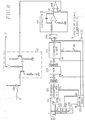
- la Fig. 8 montre en détail un circuit de réglage d'amplitude inclus dans une station terminale.
- Fig. 1 is a diagram of the architecture of a tree-to-wall optical communication network for the implementation of the emission level adjustment method according to the invention;
- Fig. 2 is a time diagram showing the distribution of outward and return frames in the central station of the network, with respect to a work-study period;
- Fig. 3 schematically shows the constitution of a frame;
- Fig. 4 schematically shows the constitution of a management field at the header of a frame;
- Fig. 5 shows the appearance of an amplitude reference word transmitted by a terminal station when it is received at the central station, as well as logic signals useful for the analysis of the amplitude reference word;
- Fig. 6 is a schematic block diagram of the central station and of a terminal station according to the invention;
- Fig. 7 shows in detail a circuit for analyzing the amplitude reference word and for developing the amplitude adjustment order included in the central station; and
- Fig. 8 shows in detail an amplitude adjustment circuit included in a terminal station.
A titre d'exemple préféré, on se réfère dans la suite à un réseau de communication à l'alternat à fibre optique ayant une architecture arborescente, comme montré à la Fig. 1. Ce réseau comprend une station centrale 1 et une pluralité K de stations terminales 2₁ à 2K. La station centrale 1 est un autocommutateur téléphonique desservant plusieurs réseaux tels que celui montré à la Fig. 1, et relié au réseau commuté général téléphonique. Chaque station terminale peut être une installation téléphonique simple, ou une installation téléphonique plus complexe, comprenant un réseau local desservant une pluralité de terminaux spécifiques, tels que poste téléphonique, télécopieur, terminal vidéotex, etc... Les secondes stations 2₁ à 2K seront désignées dans la suite par terminaux.As a preferred example, reference is made hereinafter to an alternating fiber optic communication network having a tree architecture, as shown in FIG. 1. This network includes a
Le réseau reliant la station centrale 1 aux terminaux 2₁ à 2K est composé d'un arbre dont le tronc part de la station centrale et dont les branches sont partagées en deux au niveau de coupleurs bidirectionnels 3 ayant un accès commun orienté vers la station centrale et plusieurs accès secondaires orientés vers des terminaux.The network connecting the
Comme montré schématiquement dans la Fig. 1, les terminaux 2₁ à 2K sont localisés à des distances différentes par rapport à la station centrale. Dans cette figure, un premier coupleur 3₁ est localisé à une distance L₀ de la station centrale 1 le long d'une fibre optique de tronc d'arbre FO, et est relié via des accès secondaires respectifs notamment au premier terminal 2₁ par une longueur de fibre optique L₁, et au terminal 2K par une longueur de fibre optique LK à travers au moins deux coupleurs 3₂ à 3K. Les autres accès des coupleurs 3₂ et 3K desservent d'autres terminaux, en l'occurrence les terminaux 2k à 2K-1. Ainsi, le terminal 2₁ est relié à la station centrale par une longueur de fibre optique L₀ + L₁ et un seul coupleur 3₁, tandis que le terminal 2K est relié à la station centrale à travers une longueur de fibre optique L₀ + LK à travers au moins trois coupleurs 3₁, 3₂ et 3K. Cette disparité dans les distances entre station centrale et terminaux introduit dans les signaux échangés non seulement des temps de retard de propagation différents mais également des atténuations de signaux différentes. Comme déjà dit, les moyens pour remédier à la disparité dans les retards de propagation n'appartiennent pas au cadre de la présente invention, et le lecteur se reportera à ce sujet à la demande de brevet français FR-A-2636482 déjà citée.As shown schematically in FIG. 1, the
Si on désigne par AC l'atténuation conférée par un coupleur, et AF l'atténuation linéique d'une fibre optique, les signaux échangés entre la station 1 et le terminal 2₁ subissent une atténuation égale à![]()
![]()
![]()
![]()
Si on désigne par NO le niveau d'amplitude nominal pour une réception convenable dans la station centrale 1, il apparaît, selon les localisations respectives des terminaux 2₁ et 2K selon la Fig. 1, que la puissance du transmetteur du terminal 2₁, le plus proche de la station 1, doit être inférieure à celle du terminal 2K, soit :![]()
![]()
Les échanges de signaux entre la station centrale et les divers terminaux sont transmis en un mode dit à l'alternat collectif et à accès multiples à répartition dans le temps (AMRT). Ce mode de transmission permet un dialogue entre la station centrale et les terminaux à travers un support unique, en l'occurrence une fibre optique, selon les deux sens de transmission. Selon un premier sens de transmission, appelé sens aller, ou parfois sens descendant, de la station centrale 1 vers les terminaux 2₁ à 2K, la station centrale 1 élabore et transmet des signaux à destination respectivement des terminaux sous la forme de trame aller T12. Suivant un second sens de transmission opposé au premier sens de transmission, appelé sens retour ou parfois sens montant, des terminaux 2₁ à 2K vers la station centrale 1, chacun des terminaux transmet des signaux à l'attention de la station centrale en les insérant dans des intervalles temporels bien déterminés respectifs de trames retour T21.The exchanges of signals between the central station and the various terminals are transmitted in a so-called collective alternation and multiple access time division (TDMA) mode. This transmission mode allows a dialogue between the central station and the terminals through a single medium, in this case an optical fiber, according to the two directions of transmission. According to a first direction of transmission, called forward direction, or sometimes downward direction, from the
Par exemple, en se référant à la Fig. 2, si la fréquence à l'alternat est égale à 2 kHz, soit une période d'alternat TA = 500 µs, il faut que chaque trame T12, T21 ait une longueur inférieure à 250 µs pour tenir compte du temps de propagation aller/retour maximal entre la station 1 et le terminal le plus éloigné, soit un temps TP qui inclut également un temps de garde nécessaire au basculement du mode transmission au mode réception dans chacune des stations, station centrale et terminal. Par exemple, si on considère que la transmission de l'information s'effectue au débit réel de 4,096 Mbit/s, soit un temps bit égale à 0,244 µs, une trame T12, T21 comportant 800 bits et donc ayant une durée de 195,3 µs confère un temps maximal TP = 109,4 µs, temps plus que nécessaire pour échanger des signaux avec un terminal à une distance de quelques kilomètres de la station centrale, à travers quelques coupleurs.For example, referring to FIG. 2, if the alternation frequency is equal to 2 kHz, ie an alternation period TA = 500 µs, each frame T12, T21 must be less than 250 µs in length to take account of the forward propagation time / maximum return between
Comme montré en détail à la Fig. 3, particulièrement pour la trame aller T12, une trame est composée d'un champ de gestion GES et de K secteurs réservés aux terminaux d'abonné. Selon l'exemple précédent, le champ de gestion comprend 32 bits, et K = 8 secteurs d'abonné ayant chacun 96 bits, soit 800 bits par trame.As shown in detail in FIG. 3, particularly for the forward frame T12, a frame is composed of a GES management field and K sectors reserved for subscriber terminals. According to the previous example, the management field comprises 32 bits, and K = 8 subscriber sectors each having 96 bits, or 800 bits per frame.
Un secteur de rang donné n'est pas assigné une fois pour toutes à un terminal, mais est dédié à un terminal en fonction des disponibilités des autres secteurs. Par exemple, lors d'une demande de communication, le secteur IT2 de rang 2 peut être affecté au terminal 2K-1 de rang K-1. Cette attribution d'intervalles temporels multiplexés IT₁ à ITK formant les secteurs est déterminée par la station centrale 1 en fonction de la distance entre cette station et le terminal demandeur, selon un procédé analogue à celui décrit dans la demande de brevet français précitée. Chaque secteur est destiné à convoyer de l'information proprement dite entre le terminal demandeur et un autre terminal éloigné à travers la station centrale 1.A given rank sector is not assigned once and for all to a terminal, but is dedicated to a terminal according to the availability of other sectors. For example, during a communication request, the IT2 sector of
Le champ de gestion GES est composé d'un mot de verrouillage de trame MVT, d'une adresse de terminal, appelé jeton J, d'un mot de commande MC, d'information de commande IC, et d'autres bits de gestion n'appartenant pas au cadre de la présente invention et désignés par AG.The GES management field is composed of a frame locking word MVT, a terminal address, called a J token, a control word MC, control information IC, and other management bits. outside the scope of the present invention and designated by AG.
Le mot de verrouillage de trame MVT est destiné, d'une manière classique, à synchroniser les bases de temps incluses dans les terminaux d'abonné 2₁à 2K, jouant le rôle d'esclave, sur l'horloge incluse dans la station centrale 1, jouant le rôle de station maître. Notamment à partir de la détection de ce mot de verrouillage de trame, chaque terminal récupère l'horloge bit HB, ici égale à 4,096 MHz.The frame locking word MVT is intended, in a conventional manner, to synchronize the time bases included in the
Le jeton J est constitué par le numéro 1 à K du terminal 2₁ à 2K auxquels sont destinées les informations MC et IC qui suivent dans le champ de gestion. Lorsque K = 8, le jeton J est constitué par un mot à 3 bits. Pour éviter toute erreur, c'est-à-dire notamment pour éviter qu'un terminal déjà synchronisé ne réponde pas à la station centrale suite à une erreur dans la transmission du jeton, un terminal d'abonné doit détecter son numéro en tant que jeton dans deux trames aller successives pour en déduire que les informations MC et IC particulièrement pour une transmission du mot MVT le concernent.The token J is constituted by the
Le champ MC est constitué par différents ordres de commande codés selon un protocole d'échange entre la station centrale et les terminaux. Ces ordres peuvent concerner la mise en service d'un terminal, c'est-à-dire d'une part l'attribution à ce terminal d'un secteur disponible IT₁ à ITK, et d'autre part une procédure pour le réglage progressif du niveau d'amplitude du transmetteur du terminal, comme on le verra dans la suite. Les ordres de commande peuvent également concerner des surveillances périodiques des terminaux, en vue de régler leur niveau d'amplitude de transmission en fonction du vieillissement des composants internes aux terminaux, et, bien entendu, peuvent concerner toutes demandes de communication d'arrivée ou de départ entre la station centrale et chaque terminal, et donc l'affectation d'un secteur d'information IT₁ à ITK dédié à ce terminal.The MC field consists of different control orders coded according to an exchange protocol between the central station and the terminals. These orders may relate to the commissioning of a terminal, that is to say on the one hand the allocation to this terminal of an available sector IT₁ to IT K , and on the other hand a procedure for the adjustment progressive amplitude level of the terminal transmitter, as will be seen below. The control orders can also relate to periodic monitoring of the terminals, with a view to regulating their level of transmission amplitude as a function of the aging of the components internal to the terminals, and, of course, can relate to all requests for incoming or outgoing communication. departure between the central station and each terminal, and therefore the allocation of an IT₁ to IT K information sector dedicated to this terminal.
Le champ IC contient des valeurs associées aux ordres de commande incluses dans le champ MC, par exemple une valeur numérique associée à une sommation ordonnée par un mot codé inclus dans le champ MC. Ces informations complémentaires de gestion servent à de nombreuses fonctions, et sont toutes exprimées sous forme numérique.The IC field contains values associated with the control orders included in the MC field, for example a numerical value associated with a summation ordered by a coded word included in the MC field. This additional management information serves many functions, and is all expressed in digital form.
Dans le sens retour, dit également montant, la trame T21 a une structure analogue à la trame T12, et comprend un champ de gestion ainsi que K secteurs attribués aux terminaux. Pour une même communication relative à un terminal, les deux secteurs qui lui sont attribués ont un même rang dans les trames T12 et T21. Le champ de gestion dans la trame retour ne comprend pas de mot de verrouillage, et l'ensemble des champs J, MC et IC relatifs à un terminal en cours d'échange protocolaire avec la station centrale a une position variable dans le champ GES, qui dépend de la distance de ce terminal à la station centrale.In the return direction, also known as the uplink, the frame T21 has a structure similar to the frame T12, and includes a management field as well as K sectors allocated to the terminals. For the same communication relating to a terminal, the two sectors which are allocated to it have the same rank in the frames T12 and T21. The management field in the return frame does not include a locking word, and all the fields J, MC and IC relating to a terminal in the process of protocol exchange with the central station has a variable position in the GES field, which depends on the distance from this terminal to the central station.
Lorsqu'un terminal est en phase de réglage du niveau d'amplitude de son transmetteur, le champ IC est composé d'un mot de référence d'amplitude MRA constitué par un nombre déterminé N de bits à l'état "1" qui constitue une information analogique permettant à la station centrale d'en déduire le niveau de puissance auquel est réglé le circuit d'émission du terminal, en comparant l'amplitude de chaque bit à l'état "1" du mot MRA reçu à des seuils prédéterminés NF, NI, NS. L'absence de confusion sur la provenance du mot de référence d'amplitude MRA dans la station centrale résulte de l'introduction du mot MRA dans le champ de gestion GES de la trame retour T21 dès la fin de la réception de la trame aller T12 par le terminal en question.When a terminal is in the phase of adjusting the amplitude level of its transmitter, the field IC is composed of a reference word of amplitude MRA constituted by a determined number N of bits in the state "1" which constitutes analog information enabling the central station to deduce therefrom the power level to which the terminal's transmission circuit is adjusted, by comparing the amplitude of each bit with the state "1" of the word MRA received at predetermined thresholds NF, NI, NS. The absence of confusion on the origin of the amplitude reference word MRA in the central station results from the introduction of the word MRA into the GES management field of the return frame T21 as soon as the reception of the outgoing frame T12 is received. through the terminal in question.
Ainsi, lorsque le terminal a détecté son numéro en tant que jeton J dans une trame T12, puis dans le champ suivant MC une commande de transmission du mot MRA, soit à un temps tD, le terminal attend au cours d'une seconde phase jusqu'à un temps tA correspondant à la réception du reste de la trame aller T12 au niveau de ce terminal, pour transmettre le mot MRA avec un niveau initial INI vers la station centrale 1. Pendant le temps de propagation TP, la station centrale ne reçoit et n'identifie qu'un seul mot MRA provenant du terminal en cours de réglage d'amplitude. Bien entendu, ceci suppose que les autres terminaux en service sont déjà calés temporellement.Thus, when the terminal has detected its number as a token J in a frame T12, then in the next field MC a command to transmit the word MRA, ie at a time t D , the terminal waits during a second phase up to a time t A corresponding to the reception of the rest of the forward frame T12 at this terminal, to transmit the word MRA with an initial level INI to the
Après analyse de l'amplitude des bits "1" du mot MRA reçu, la station centrale envoie, toujours avec l'adresse J du terminal, un ordre de modification du niveau de transmission (MC+IC[UD]) au terminal en question. Puis à une quatrième phase, le terminal retransmet le mot de référence d'amplitude MRA ayant une nouvelle amplitude modifiée selon les commandes ordonnées par la station centrale.After analysis of the amplitude of bits "1" of the word MRA received, the central station sends, always with the address J of the terminal, an order to modify the transmission level (MC + IC [UD]) to the terminal in question . Then in a fourth phase, the terminal retransmits the amplitude reference word MRA having a new amplitude modified according to the commands ordered by the central station.
Des cycles comprenant la dernière phase de transmission aller et la dernière phase de transmission retour sont itérés jusqu'au réglage effectif de l'amplitude du transmetteur du terminal au niveau nominal N0 reçu dans la station 1. Le nombre de cycles de réglage est compté dans la station centrale, et si celui-ci dépasse un nombre prédéterminé, le terminal est déclaré "en panne".Cycles comprising the last forward transmission phase and the last return transmission phase are iterated until the effective adjustment of the amplitude of the terminal transmitter to the nominal level N0 received in
En dehors de la période de mise en service des terminaux d'abonné et de leur remise en service en cas de panne majeure où le niveau initial d'amplitude des signaux à transmettre est sensiblement égal à un niveau minimal MIN bien inférieur au niveau nominal requis N0, la station centrale effectue cycliquement un balayage des terminaux afin de régler périodiquement le niveau d'amplitude de transmission des terminaux, qui varie en fonction du vieillissement et des dérives thermiques des composants inclus dans chaque terminal, et d'une manière générale de l'environnement du terminal.Outside the period of commissioning of subscriber terminals and their return to service in the event of a major breakdown where the initial level of amplitude of the signals to be transmitted is substantially equal to a minimum MIN level much lower than the nominal level required N0, the central station performs a cyclical scan of the terminals in order to periodically adjust the level of amplitude of transmission of the terminals, which varies according to the aging and thermal drifts of the components included in each terminal, and in general of the terminal environment.
Le principe du réglage du niveau d'amplitude dans un terminal est le suivant, en référence à la Fig. 5.The principle of adjusting the amplitude level in a terminal is as follows, with reference to FIG. 5.
Le niveau d'amplitude détecté sur le mot de référence d'amplitude MRA est jugé correct dans la station centrale 1, si celui-ci est compris entre un niveau supérieur NS et un niveau inférieur NI tels que (NS+NI)/2= N0 et avec de préférence, NI = 0,9 N0 et NS = 1,1 N0. En dehors de l'intervalle NS, NI, le niveau d'amplitude est jugé insatisfaisant, et il est nécessaire de l'incrémenter lorsque le niveau est inférieur à NI et de le décrémenter lorsque le niveau est supérieur à NS. Afin d'accélérer la procédure de réglage, un troisième niveau est défini comme nettement inférieur au niveau nominal N0, ce troisième niveau NF étant typiquement égal à 0,1 N0. Lorsque le niveau du signal reçu est supérieur à NF, l'incrémentation ou décrémentation se fait pas à pas, un pas étant par exemple égal à 0,01 NO. Lorsque le niveau reçu est inférieur à NF, l'incrémentation s'effectuera par des sauts de 8 pas entre deux cycles de réglage.The amplitude level detected on the amplitude reference word MRA is considered correct in the
Le niveau initial INI des signaux transmis par un terminal à raccorder au réseau arborescent est typiquement compris entre NI et NF, si bien que pour un terminal à raccorder à proximité de la station centrale, le réglage s'effectue très rapidement, tandis que pour un terminal à raccorder à une distance relativement grande de la station centrale, le réglage s'effectue en plusieurs cycles.The initial level INI of the signals transmitted by a terminal to be connected to the tree network is typically between NI and NF, so that for a terminal to be connected near the central station, the adjustment is made very quickly, while for a terminal to be connected at a relatively large distance from the central station, the adjustment is carried out in several cycles.
On décrit maintenant les divers moyens dans la station centrale 1 et dans un terminal quelconque, désigné par le repère 2, ayant trait particulièrement à l'analyse du niveau d'amplitude et à la transmission du résultat de cette analyse dans la station centrale, d'une part, et à la réception du résultat de cette analyse dans le terminal et au réglage de l'amplitude correspondant, d'autre part.The various means are now described in the
Comme montré schématiquement à la Fig. 6, la station centrale 1 comprend classiquement, du côté du réseau arborescent, un coupleur optique à trois accès, couplant une fibre optique de terminaison FO du tronc d'arbre du réseau à un photorécepteur, du genre photodiode PIN, et à un photo-émetteur du genre diode LED, ou diode laser, à travers de courtes fibres optiques intermédiaires FR et FA. La diode PIN est connectée à un circuit de réception et d'amplification 13 transmettant les trames retour T21 à un circuit de démultiplexage 14 inclus dans une unité de commutation de canaux temporels UCO de la station centrale 1. Dans le sens aller, l'unité de commutation UCO comprend en sortie un circuit de multiplexage 15 pour former périodiquement les trames aller T12, et en particulier pour paquetiser les données proprement dites destinées respectivement aux terminaux sous forme de secteurs à 96 bits, et pour introduire des informations dans le champ de gestion GES. Les trames T12 sont transmises en série à un circuit d'émission 16 relatif à l'amplification et la polarisation de la diode LED. En outre, selon l'invention, la station centrale 1 comprend un circuit d'analyse du mot MRA et d'élaboration d'ordre de réglage d'amplitude UD, 17.As shown schematically in FIG. 6, the
En se reportant à la Fig. 7, le circuit 17 comprend trois comparateurs de tension 171S, 171I et 171F, trois registres à décalage 172S, 172I et 172F, trois portes OU 173S, 173I et 173F, un codeur logique 174 et un circuit de commande de registres 175.Referring to FIG. 7, the
Les comparateurs 171S, 171I et 171F reçoivent respectivement à des premières entrées inverse, directe et directe les niveaux de tension de référence NS, NI et NF. Des secondes entrées respectivement directe, inverse et inverse des comparateurs 171S, 171I et 171F reçoivent le signal SR récupéré par le circuit de réception 13 et convoyant les trames retour T21. Un signal logique à la sortie de l'un de ces trois comparateurs est à l'état "1" lorsque la tension à l'entrée directe (+) du comparateur est supérieure à la tension à l'entrée inverse (-) de ce même comparateur.The
Les sorties des trois comparateurs 171S, 171I et 171F sont reliées respectivement aux entrées des registres à décalage 172S, 172I et 172F ayant chacun un nombre d'étages à un bit égal à N-1. Les portes OU 173S, 173I et 173F ont N-1 entrées respectivement reliées aux sorties des registres 172S, 172I et 172F et des sorties reliées à des entrées respectives 174S, 174I et 174F du codeur 174.
Lorsque le niveau du signal reçu SR est compris entre les niveaux inférieur NI et supérieur NS pendant N-1 temps bits consécutifs, la sortie des trois portes OU 173S, 173I et 173F est à l'état "0", et deux sorties U et D du codeur 174 sont également à l'état "0". Comme cela apparaît dans le tableau ci-après résumant le codage des résultats des comparaisons dans les trois comparateurs, le niveau "analogique" du signal SR peut être compris seulement dans quatre plages de tension prédéterminées si bien que le résultat des comparaisons n'est codé que sur deux bits U et D.

When the level of the received signal SR is between the lower levels NI and higher NS for N-1 consecutive bit time, the output of the three OR
Le circuit de commande de registre 175 détecte le début d'un mot de référence d'amplitude MRA afin que les niveaux des bits de ce mot soient successivement quantifiés et enregistrés dans les registres à décalage. Le circuit 175 comprend essentiellement une porte OU à deux entrées 1751, une bascule RS 1752, un compteur modulo N 1753 et une porte ET à deux entrées 1754. Une entrée inverse de la porte 1751 est reliée à la sortie du troisième comparateur 171F, tandis qu'une entrée directe de la porte 1751 reçoit une impulsion de fin de temps de propagation IF, précédant sensiblement le début de la trame aller T12 et produite par une base de temps BT dans l'unité de commutation UCO. La bascule 1752 a une entrée de mise à "1" S reliée à la sortie de la porte 1751, une sortie Q reliée à une entrée de la porte 1754 et à une entrée de comptage CO du compteur 1753, et une entrée de mise à "0" R reliée à une sortie du compteur 1753. La seconde entrée de la porte 1754 et une entrée d'horloge CL du compteur 1753 reçoivent le signal d'horloge HB à la fréquence de 4,096 Mbit/s de la base de temps BT. La sortie de la porte 1754 est reliée aux entrées d'horloge CL des trois registres à décalage 172S, 172I, 172F.The
Les registres à décalage sont remis à zéro par leur entrée R en réponse au front montant du signal d'horloge à l'alternat de période TA (Fig. 2), précédant la réception d'une trame retour T21. Comme montré à la Fig. 5, dès que le niveau du signal reçu SR franchit le seuil de niveau faible NF, la sortie de la porte 1751 passe à l'état "1" ce qui déclenche le comptage d'impulsions d'horloge dans le compteur 1753 et "l'échantillonnage" des sorties des comparateurs et donc le décalage des différents échantillons obtenus dans les registres à décalage, à la fréquence d'horloge HB. Les opérations précédentes sont arrêtées dés que le compteur 1753 a compté N impulsions d'horloge, ce qui remet à zéro la bascule 1752, et par suite ferme la porte ET 1754. Si tous les bits dans les trois registres 172S, 173I et 173F sont à "0" pendant le comptage précédent, le niveau des bits "1" du mot de référence d'amplitude MRA est compris entre NI et NS et est donc correct. Si au moins l'un des, ou plusieurs des étages du registre 172S, respectivement du registre 172I, sont à l'état "1", le niveau du signal reçu SR est trop élevé et il faut par conséquent diminuer l'amplitude du signal émis dans le terminal 2, respectivement est trop faible et il faut augmenter l'amplitude du signal émis dans le terminal 2. Si à la fois au moins des étages de même rang dans les registres 172S et 172I sont à l'état "1", le niveau du signal reçu SR est beaucoup trop faible, puisqu'il est inférieur au niveau NF, et l'amplitude du signal émis dans le terminal 2 doit être augmentée très rapidement, par exemple avec 8 pas chaque fois, jusqu'à atteindre un niveau correspondant à un niveau de réception dans la station 1 supérieur à NF.The shift registers are reset to zero by their input R in response to the rising edge of the clock signal at the alternation of period TA (FIG. 2), preceding the reception of a return frame T21. As shown in Fig. 5, as soon as the level of the signal received SR crosses the low level threshold NF, the output of
Si pendant la fenêtre de largeur TP entre la fin d'émission d'une trame aller T12 et le début de réception d'une trame retour T21, le niveau du signal reçu SR n'atteint pas le niveau faible NF, c'est-à-dire si la sortie du comparateur 171F reste à l'état "1", cette sortie n'autorisera pas le déclenchement du comptage dans le compteur 1753. Dans ce cas, l'impulsion IF à la fin de la fenêtre TP au cours de laquelle normalement le mot MRA doit être reçu, met elle-même à "1" la bascule 1752, et par conséquent autorise par défaut le comptage de N impulsions d'horloge par le compteur 1753 ainsi que les décalages dans les registres 172S, 172I et 172F. A la fin de ce dernier comptage, les sorties des portes 173S, 173I et 173F sont respectivement à l'état "0", "1" et "1" ce qui correspond à un codage "11" aux sorties U et D du codeur 174.If during the width window TP between the end of transmission of a forward frame T12 and the start of reception of a return frame T21, the level of the received signal SR does not reach the low level NF, that is that is to say if the output of
Il est à noter que pour un mot MRA ayant N bits, le nombre d'étages dans le registre à décalage peut être choisi inférieur à N par exemple N-2, N-3, etc... Le nombre d'étages dans ces registres est choisi d'autant plus grand que la détection du mot MRA est précise. Le nombre N-1 d'étages par registre est choisi de préférence pour que l'échantillonnage des résultats des comparaisons tienne compte de la pente du front montant du premier bit du mot reçu MRA et du temps de réponse des comparateurs.It should be noted that for a word MRA having N bits, the number of stages in the shift register can be chosen lower than N for example N-2, N-3, etc. The number of stages in these registers is chosen all the greater as the detection of the word MRA is precise. The number N-1 of stages per register is preferably chosen so that the sampling of the results of the comparisons takes into account the slope of the rising edge of the first bit of the word received MRA and the response time of the comparators.
Comme montré également à la Fig. 7, le codeur 174 comprend par exemple une porte ET 1741 à deux entrées, deux portes ET à trois entrées 1742 et 1743 et une porte OU à deux entrées 1744 afin que les sorties U et D des portes 1741 et 1744 soient aux états respectifs selon le tableau précédent. La sortie de la porte OU 173S en sortie du registre 172S est reliée à une entrée inverse de la porte 1741, à une entrée directe de la porte 1742 et à une première entrée inverse de la porte 1743. La sortie de la porte OU 173I en sortie du registre à décalage 1721 est reliée à une entrée directe de la porte 1741, à une première entrée inverse de la porte 1742 et à une première entrée directe de la porte 1743. La sortie de la porte OU 173F en sortie du registre à décalage 172F est reliée à une seconde entrée inverse de la porte 1742 et à une seconde entrée directe de la porte 1743. Les sorties des portes 1742 et 1743 sont reliées aux entrées respectives de la porte OU 1744.As also shown in FIG. 7, the
Les deux bits U et D sont alors mémorisés dans une mémoire tampon inclus dans le circuit de multiplexage 15, et sont insérés dans le champ d'informations de commande IC d'une trame aller T12, à la suite d'un mot de commande MC invitant à un réglage d'amplitude le terminal en question 2 dont l'adresse est contenue dans le jeton J de la trame T12.The two bits U and D are then stored in a buffer memory included in the
En se reportant maintenant à la Fig. 6, un terminal 2 comprend, du côté du réseau arborescent, un coupleur optique à trois accès 20 couplant une fibre optique respective fo du réseau arborescent à un circuit de réception 21 à diode PIN et à un circuit d'émission 22 à diode LED à travers deux fibres optiques intermédiaires fa et fr. Le terminal comprend, en outre, une unité de traitement de données UT dans laquelle un circuit de démultiplexage 23 est relié à la sortie du circuit réception 21, et un circuit de multiplexage 24 dessert l'entrée du circuit d'émission 22. Selon l'invention, il est également prévu un circuit intermédiaire entre les moyens de réception 21-23 et les moyens d'émission 24-22 dit circuit de réglage d'amplitude 25.Referring now to FIG. 6, a
Le circuit de démultiplexage 23 est associé à une base de temps 231 qui récupère les fréquences de trame et de bit à partir du mot de verrouillage de trame MVT contenu en en-tête des trames aller T12, et des moyens pour détecter dans le champ de gestion GES, le numéro du terminal en tant que jeton J. En outre, lorsque le circuit de démultiplexage 23 reconnaît un mot de réglage d'amplitude dans le champ MC, les deux bits U et D contenus dans le champ IC sont appliqués aux entrées du circuit de réglage d'amplitude 25. Le circuit de multiplexage fournit également aux circuits internes du terminal, les données proprement dites attribuées à celui-ci et insérées dans le secteur IT dédié au terminal.The
Comme montré en détail à la Fig. 8, le circuit de réglage d'amplitude 25 comprend essentiellement un compteur-décompteur à 8 bits 252, une mémoire enfichable PROM de linéarisation 253, un décompteur à 10 bits 254, une bascule RS 255 et un intégrateur 256. Les tailles du compteur-décompteur, de la mémoire PROM et du décompteur sont données uniquement à titre d'exemple.As shown in detail in FIG. 8, the
Une entrée d'autorisation de comptage EU du compteur 252 reçoit directement le bit U, tandis qu'une entrée de décomptage ED du compteur-décompteur 252 reçoit le bit D à travers une porte NON-ET 257 et une porte ET 258. Les deux entrées de la porte 257 reçoivent les bits U et D. Une entrée de la porte 258 reçoit le bit D tandis que l'autre entrée de cette porte est reliée à la sortie de la porte 257. Dans ces conditions, le compteur-décompteur 252 passe en état de comptage lorsque le niveau de signal reçu SR dans la station centrale 1 est inférieur au niveau NI, soit un mot UD = "10" ou "11", et le compteur-décompteur 252 passe en état de décomptage uniquement lorsque le niveau du signal reçu dans la station centrale est inférieur à NS ce qui correspond à un mot UD = "01". Lorsque l'amplitude du signal reçu SR dans la station centrale 1 est correcte, les entrées EU et UD sont à l'état "0", et le compte du compteur-décompteur 252 n'est pas modifié.A counting authorization input EU of the
D'autre part, les bits U et D délivrés par le circuit de démultiplexage 23 sont également combinés à des entrées E1 et E8 de la base de temps 231 à travers une porte OU-Exclusif 232 et une autre porte ET à deux entrées 233. Lorsque la sortie de la porte 232 reliée à l'entrée E1 est à l'état "1", la base de temps 231 n'applique qu'une impulsion d'horloge à une entrée d'horloge CL du compteur-décompteur 252 de manière à augmenter ou à diminuer d'un pas égal typiquement à (0,01 NO), l'amplitude du signal à émettre par le terminal. Lorsque la sortie de la porte ET 233 reliée à l'entrée E8 est à l'état "1", la base de temps 231 applique brièvement un nombre déterminé d'impulsions d'horloge, par exemple huit, à l'entrée d'horloge CL du compteur-décompteur 252 afin que l'amplitude du signal à émettre par le circuit 22 soit augmentée rapidement.On the other hand, the bits U and D delivered by the
La mémoire morte programmable 253 est adressée en lecture par des adresses à 8 bits fournit par le compteur-décompteur 252, et fait correspondre à chaque adresse, la valeur numérique d'une amplitude. Ainsi la mémoire 253 réalise la conversion "numérique-analogique" entre une amplitude codée et la valeur réelle de l'amplitude. Initialement, lors de la mise en marche du terminal 2, le compteur 252 est à zéro, ce qui correspond, comme déjà dit, à une amplitude minimum initiale MIN comprise sensiblement entre les niveaux NS et NI.The programmable read-
L'entrée de commande de lecture L de la mémoire 253, l'entrée de décomptage ED du décompteur 254 ainsi que l'entrée de mise à un S de la bascule 255 reçoivent des impulsions d'horloge à une fréquence FM multiple de la fréquence d'alternat, typiquement à une fréquence égale à 8 x 2 = 16 kHz. Ainsi en réponse à une impulsion d'horloge, la valeur numérique d'amplitude est lue dans la mémoire 253, sous la forme d'un mot de 10 bits qui est chargé dans le décompteur 254, et la sortie Q de la bascule 255 reliée à l'entrée de l'intégrateur 256 est mise à "1". Le décompteur 254 reçoit des impulsions d'horloge à la fréquence 2x FM où x est égal typiquement à 10. La sortie de retenue B du décompteur 254 est reliée à l'entrée R de la bascule 255.The read control input L of the
Ainsi, dès que le décompteur 254 a décompté un nombre d'impulsions d'horloge à la fréquence (2x.FM) égal à la valeur numérique de l'amplitude lue dans la mémoire 253, la bascule 25 est mise à zéro. L'intégrateur 256 réalise ainsi la conversion de la valeur numérique de l'amplitude en une tension analogique. Cette tension analogique VS est appliquée au circuit d'émission 22 à travers un amplificateur-suiveur 259. Une entrée de modulation du circuit d'émission 22 reçoit les signaux numériques à transmettre à la station centrale 1, établis par le circuit de multiplexage 24.Thus, as soon as the
Pour assurer la stabilité de la tension VS, les valeurs de résistance et de capacité dans l'intégrateur 256 sont convenablement dimensionnées. Toutefois, la constante d'intégration de l'intégrateur est compatible avec le débit des signaux échangés entre la station 1 et le terminal 2. C'est pourquoi, en pratique, pour une période d'alternat égale à 2 kHz, il a été choisi de stabiliser chaque valeur VS à raison de (FM.TA)=8 cycles d'intégration par période d'alternat. En fait, sachant que les bits U et D sont détectés et donc disponibles au début de la trame aller T12, après détection du mot IC, et que le nouveau réglage de l'amplitude d'émission est effectif à la fin de cette trame, après environ 190 µs succèdant à la détection du mot IC, deux à trois cycles effectifs de décomptage dans le décompteur 254 sont pris en compte pour modifier rapidement l'amplitude du signal d'émission. Le nombre de 2 à 3 cycles est fonction du produit TRxFM, c'est-à-dire du nombre d'impulsions FM pendant la durée de trame TR, ou plus précisément tA-tD, selon les Figs. 3 et 4. Ainsi, après le réglage d'amplitude d'émission dans le circuit 22, un mot MRA="11...1" peut être produit par le démultiplexeur 24 sous la commande de la base de temps 231, au début de la fenêtre TP, après réception de la trame T12.To ensure the stability of the voltage VS, the resistance and capacitance values in the
Claims (6)
caractérisé par les étapes suivantes :
et répétitions du cycle comprenant lesdites comparaison, émission avec ordre de modification de niveau et émission ayant un niveau modifié, tant qu'une comparaison n'est pas satisfaite si les répétitions sont inférieures à un nombre prédéterminé.
characterized by the following stages:
and repetitions of the cycle comprising said comparison, transmission with level modification order and transmission having a modified level, as long as a comparison is not satisfied if the repetitions are less than a predetermined number.
Applications Claiming Priority (2)
| Application Number | Priority Date | Filing Date | Title |
|---|---|---|---|
| FR9008211A FR2664112B1 (en) | 1990-06-29 | 1990-06-29 | METHOD FOR ADJUSTING THE TRANSMISSION LEVEL OF TERMINALS IN A LONG-TERM TRANSMISSION NETWORK. |
| FR9008211 | 1990-06-29 |
Publications (2)
| Publication Number | Publication Date |
|---|---|
| EP0465300A1 true EP0465300A1 (en) | 1992-01-08 |
| EP0465300B1 EP0465300B1 (en) | 1995-09-13 |
Family
ID=9398147
Family Applications (1)
| Application Number | Title | Priority Date | Filing Date |
|---|---|---|---|
| EP19910401715 Expired - Lifetime EP0465300B1 (en) | 1990-06-29 | 1991-06-26 | Method for controlling the transmission level of terminal stations in a time-sharing communications network |
Country Status (3)
| Country | Link |
|---|---|
| EP (1) | EP0465300B1 (en) |
| DE (1) | DE69112927T2 (en) |
| FR (1) | FR2664112B1 (en) |
Cited By (1)
| Publication number | Priority date | Publication date | Assignee | Title |
|---|---|---|---|---|
| US5272694A (en) * | 1991-03-21 | 1993-12-21 | France Telecom | Synchronization of terminal stations in a multirate half-duplex tree-structured network |
Citations (3)
| Publication number | Priority date | Publication date | Assignee | Title |
|---|---|---|---|---|
| EP0049670A1 (en) * | 1980-10-08 | 1982-04-14 | Gérard Pays | Device to minimize far-end crosstalk between lines with digital time-shared transmission |
| WO1984004638A1 (en) * | 1983-05-12 | 1984-11-22 | American Telephone & Telegraph | Communication network |
| WO1988009093A1 (en) * | 1987-05-06 | 1988-11-17 | British Telecommunications Public Limited Company | Control of optical systems |
-
1990
- 1990-06-29 FR FR9008211A patent/FR2664112B1/en not_active Expired - Fee Related
-
1991
- 1991-06-26 DE DE1991612927 patent/DE69112927T2/en not_active Expired - Lifetime
- 1991-06-26 EP EP19910401715 patent/EP0465300B1/en not_active Expired - Lifetime
Patent Citations (3)
| Publication number | Priority date | Publication date | Assignee | Title |
|---|---|---|---|---|
| EP0049670A1 (en) * | 1980-10-08 | 1982-04-14 | Gérard Pays | Device to minimize far-end crosstalk between lines with digital time-shared transmission |
| WO1984004638A1 (en) * | 1983-05-12 | 1984-11-22 | American Telephone & Telegraph | Communication network |
| WO1988009093A1 (en) * | 1987-05-06 | 1988-11-17 | British Telecommunications Public Limited Company | Control of optical systems |
Non-Patent Citations (1)
| Title |
|---|
| ELECTRONIC LETTERS vol. 23, no. 19, Novembre 1987, ENAGE, GB pages 1255 - 1257; STERN ET AL.: 'Passive optical local networks for telephony applications and beyond. ' * |
Cited By (1)
| Publication number | Priority date | Publication date | Assignee | Title |
|---|---|---|---|---|
| US5272694A (en) * | 1991-03-21 | 1993-12-21 | France Telecom | Synchronization of terminal stations in a multirate half-duplex tree-structured network |
Also Published As
| Publication number | Publication date |
|---|---|
| FR2664112B1 (en) | 1993-05-28 |
| DE69112927T2 (en) | 1996-05-15 |
| FR2664112A1 (en) | 1992-01-03 |
| EP0465300B1 (en) | 1995-09-13 |
| DE69112927D1 (en) | 1995-10-19 |
Similar Documents
| Publication | Publication Date | Title |
|---|---|---|
| EP0555596B1 (en) | Method for determining the propagation time between a remote terminal station and a central terminal station, in a bidirectional point-to-multipoint transmission system | |
| EP0041429B1 (en) | Process and device for the synchronization of digital signals | |
| CA2557425C (en) | Apparatus and method for compensating for data degardation | |
| FR2533094A1 (en) | METHOD OF CONTROLLING A DIGITAL TRANSMISSION SYSTEM, SYSTEM AND REPEATERS APPLYING SAID METHOD | |
| EP0027413B1 (en) | System for the simultaneous integral multiple-access transmission over optical fibre transmission lines | |
| EP0505281B1 (en) | Synchronisation of terminal stations in a multirate half duplex tree network | |
| EP0053958A1 (en) | Process for the parallel/series conversion of a digital parallel sequence | |
| CA2138107C (en) | Method and device for the fine synchronization of atm cells in optical atm nodes | |
| EP0933895A1 (en) | Method for detecting one or more free channels in an optical time multiplexed signal, a device for implementation and an application of the device | |
| EP0108692A1 (en) | Method and installation for digital data transmission | |
| EP0027410A1 (en) | Switching method for time division multiplex signals transmitted by a carrier wave, particularly an optical wave, and device for putting it into use | |
| EP0064923B1 (en) | System for the phase synchronization of digital data streams, and its application to the commutation of said data streams | |
| EP0465300B1 (en) | Method for controlling the transmission level of terminal stations in a time-sharing communications network | |
| FR2597689A1 (en) | DEVICE FOR THE RECOVERY OF RHYTHM SUITABLE IN PARTICULAR FOR AN INFORMATION TRANSMISSION SYSTEM USING IN A SENSE OF TRANSMISSION THE PRINCIPLE SAID OF A.M.R.T. | |
| EP0843931B1 (en) | Communication method using an optical bus simultaneously supporting different data rates | |
| EP1592159A2 (en) | Optical transmission network with tree structure | |
| EP0555595B1 (en) | Method of time slot assignment in a time division multiple access transmission system | |
| FR2606240A1 (en) | TRANSMITTER-RECEIVER FOR VERIFYING TRANSMISSION LINKS AND APPARATUS HAVING THE SAME | |
| FR2636482A1 (en) | Method of synchronisation for the multiplexing of words in a fibre optics star communication network | |
| FR2665992A1 (en) | METHOD FOR RECEIVING WAVELENGTH MULTIPLEX SIGNALS, IN PARTICULAR FOR MONITORING ENERGY TRANSPORT LINES. | |
| EP0384847A1 (en) | Method and device to gain access to an extended area network | |
| CA3176135C (en) | Method for establishing communication in an optical access network | |
| EP0509434B1 (en) | Transmission installation with monitored optical link | |
| JPH03140025A (en) | Optical space communication system | |
| EP0443482A1 (en) | Arrangement for linking digital terminals to a single, higher speed port |
Legal Events
| Date | Code | Title | Description |
|---|---|---|---|
| PUAI | Public reference made under article 153(3) epc to a published international application that has entered the european phase |
Free format text: ORIGINAL CODE: 0009012 |
|
| AK | Designated contracting states |
Kind code of ref document: A1 Designated state(s): DE FR GB |
|
| 17P | Request for examination filed |
Effective date: 19911206 |
|
| 17Q | First examination report despatched |
Effective date: 19940418 |
|
| GRAA | (expected) grant |
Free format text: ORIGINAL CODE: 0009210 |
|
| AK | Designated contracting states |
Kind code of ref document: B1 Designated state(s): DE FR GB |
|
| GBT | Gb: translation of ep patent filed (gb section 77(6)(a)/1977) |
Effective date: 19950919 |
|
| REF | Corresponds to: |
Ref document number: 69112927 Country of ref document: DE Date of ref document: 19951019 |
|
| PLBE | No opposition filed within time limit |
Free format text: ORIGINAL CODE: 0009261 |
|
| STAA | Information on the status of an ep patent application or granted ep patent |
Free format text: STATUS: NO OPPOSITION FILED WITHIN TIME LIMIT |
|
| 26N | No opposition filed | ||
| REG | Reference to a national code |
Ref country code: GB Ref legal event code: IF02 |
|
| PGFP | Annual fee paid to national office [announced via postgrant information from national office to epo] |
Ref country code: GB Payment date: 20100527 Year of fee payment: 20 Ref country code: FR Payment date: 20100729 Year of fee payment: 20 Ref country code: DE Payment date: 20100610 Year of fee payment: 20 |
|
| REG | Reference to a national code |
Ref country code: DE Ref legal event code: R071 Ref document number: 69112927 Country of ref document: DE |
|
| REG | Reference to a national code |
Ref country code: DE Ref legal event code: R071 Ref document number: 69112927 Country of ref document: DE |
|
| REG | Reference to a national code |
Ref country code: GB Ref legal event code: PE20 Expiry date: 20110625 |
|
| PG25 | Lapsed in a contracting state [announced via postgrant information from national office to epo] |
Ref country code: GB Free format text: LAPSE BECAUSE OF EXPIRATION OF PROTECTION Effective date: 20110625 |
|
| PG25 | Lapsed in a contracting state [announced via postgrant information from national office to epo] |
Ref country code: DE Free format text: LAPSE BECAUSE OF EXPIRATION OF PROTECTION Effective date: 20110627 |