EP0464630B2 - Cryogenic air separation with dual product boiler - Google Patents
Cryogenic air separation with dual product boiler Download PDFInfo
- Publication number
- EP0464630B2 EP0464630B2 EP91110556A EP91110556A EP0464630B2 EP 0464630 B2 EP0464630 B2 EP 0464630B2 EP 91110556 A EP91110556 A EP 91110556A EP 91110556 A EP91110556 A EP 91110556A EP 0464630 B2 EP0464630 B2 EP 0464630B2
- Authority
- EP
- European Patent Office
- Prior art keywords
- oxygen
- nitrogen
- liquid
- product
- boiler
- Prior art date
- Legal status (The legal status is an assumption and is not a legal conclusion. Google has not performed a legal analysis and makes no representation as to the accuracy of the status listed.)
- Expired - Lifetime
Links
- 230000009977 dual effect Effects 0.000 title claims description 31
- 238000000926 separation method Methods 0.000 title claims description 21
- IJGRMHOSHXDMSA-UHFFFAOYSA-N Atomic nitrogen Chemical compound N#N IJGRMHOSHXDMSA-UHFFFAOYSA-N 0.000 claims description 164
- 239000007788 liquid Substances 0.000 claims description 96
- 229910052757 nitrogen Inorganic materials 0.000 claims description 77
- QVGXLLKOCUKJST-UHFFFAOYSA-N atomic oxygen Chemical compound [O] QVGXLLKOCUKJST-UHFFFAOYSA-N 0.000 claims description 69
- 239000001301 oxygen Substances 0.000 claims description 69
- 229910052760 oxygen Inorganic materials 0.000 claims description 69
- MYMOFIZGZYHOMD-UHFFFAOYSA-N Dioxygen Chemical compound O=O MYMOFIZGZYHOMD-UHFFFAOYSA-N 0.000 claims description 16
- 238000000034 method Methods 0.000 claims description 15
- 238000012856 packing Methods 0.000 claims description 14
- 229910001873 dinitrogen Inorganic materials 0.000 claims description 9
- 229910001882 dioxygen Inorganic materials 0.000 claims description 8
- 239000007789 gas Substances 0.000 claims description 8
- 239000012530 fluid Substances 0.000 claims description 7
- 238000009833 condensation Methods 0.000 claims description 5
- 230000005494 condensation Effects 0.000 claims description 5
- 238000001816 cooling Methods 0.000 claims description 3
- 238000010792 warming Methods 0.000 claims 3
- 239000000047 product Substances 0.000 description 32
- 239000007791 liquid phase Substances 0.000 description 7
- 239000012071 phase Substances 0.000 description 7
- 239000012808 vapor phase Substances 0.000 description 7
- 239000012141 concentrate Substances 0.000 description 6
- 238000004821 distillation Methods 0.000 description 5
- 238000004519 manufacturing process Methods 0.000 description 5
- 239000000203 mixture Substances 0.000 description 4
- 238000005057 refrigeration Methods 0.000 description 4
- 230000008016 vaporization Effects 0.000 description 3
- 238000009835 boiling Methods 0.000 description 2
- 230000006835 compression Effects 0.000 description 2
- 238000007906 compression Methods 0.000 description 2
- 238000001944 continuous distillation Methods 0.000 description 2
- 238000005194 fractionation Methods 0.000 description 2
- 239000012263 liquid product Substances 0.000 description 2
- 238000010992 reflux Methods 0.000 description 2
- 238000009834 vaporization Methods 0.000 description 2
- 238000005094 computer simulation Methods 0.000 description 1
- 230000000694 effects Effects 0.000 description 1
- 238000010438 heat treatment Methods 0.000 description 1
- 238000011068 loading method Methods 0.000 description 1
- 238000011027 product recovery Methods 0.000 description 1
- 238000011084 recovery Methods 0.000 description 1
- 239000007787 solid Substances 0.000 description 1
- 239000000126 substance Substances 0.000 description 1
Images

Classifications
-
- F—MECHANICAL ENGINEERING; LIGHTING; HEATING; WEAPONS; BLASTING
- F25—REFRIGERATION OR COOLING; COMBINED HEATING AND REFRIGERATION SYSTEMS; HEAT PUMP SYSTEMS; MANUFACTURE OR STORAGE OF ICE; LIQUEFACTION SOLIDIFICATION OF GASES
- F25J—LIQUEFACTION, SOLIDIFICATION OR SEPARATION OF GASES OR GASEOUS OR LIQUEFIED GASEOUS MIXTURES BY PRESSURE AND COLD TREATMENT OR BY BRINGING THEM INTO THE SUPERCRITICAL STATE
- F25J3/00—Processes or apparatus for separating the constituents of gaseous or liquefied gaseous mixtures involving the use of liquefaction or solidification
- F25J3/02—Processes or apparatus for separating the constituents of gaseous or liquefied gaseous mixtures involving the use of liquefaction or solidification by rectification, i.e. by continuous interchange of heat and material between a vapour stream and a liquid stream
- F25J3/04—Processes or apparatus for separating the constituents of gaseous or liquefied gaseous mixtures involving the use of liquefaction or solidification by rectification, i.e. by continuous interchange of heat and material between a vapour stream and a liquid stream for air
- F25J3/04006—Providing pressurised feed air or process streams within or from the air fractionation unit
- F25J3/04078—Providing pressurised feed air or process streams within or from the air fractionation unit providing pressurized products by liquid compression and vaporisation with cold recovery, i.e. so-called internal compression
- F25J3/0409—Providing pressurised feed air or process streams within or from the air fractionation unit providing pressurized products by liquid compression and vaporisation with cold recovery, i.e. so-called internal compression of oxygen
-
- F—MECHANICAL ENGINEERING; LIGHTING; HEATING; WEAPONS; BLASTING
- F25—REFRIGERATION OR COOLING; COMBINED HEATING AND REFRIGERATION SYSTEMS; HEAT PUMP SYSTEMS; MANUFACTURE OR STORAGE OF ICE; LIQUEFACTION SOLIDIFICATION OF GASES
- F25J—LIQUEFACTION, SOLIDIFICATION OR SEPARATION OF GASES OR GASEOUS OR LIQUEFIED GASEOUS MIXTURES BY PRESSURE AND COLD TREATMENT OR BY BRINGING THEM INTO THE SUPERCRITICAL STATE
- F25J3/00—Processes or apparatus for separating the constituents of gaseous or liquefied gaseous mixtures involving the use of liquefaction or solidification
- F25J3/02—Processes or apparatus for separating the constituents of gaseous or liquefied gaseous mixtures involving the use of liquefaction or solidification by rectification, i.e. by continuous interchange of heat and material between a vapour stream and a liquid stream
- F25J3/04—Processes or apparatus for separating the constituents of gaseous or liquefied gaseous mixtures involving the use of liquefaction or solidification by rectification, i.e. by continuous interchange of heat and material between a vapour stream and a liquid stream for air
- F25J3/04006—Providing pressurised feed air or process streams within or from the air fractionation unit
- F25J3/04078—Providing pressurised feed air or process streams within or from the air fractionation unit providing pressurized products by liquid compression and vaporisation with cold recovery, i.e. so-called internal compression
- F25J3/04084—Providing pressurised feed air or process streams within or from the air fractionation unit providing pressurized products by liquid compression and vaporisation with cold recovery, i.e. so-called internal compression of nitrogen
-
- F—MECHANICAL ENGINEERING; LIGHTING; HEATING; WEAPONS; BLASTING
- F25—REFRIGERATION OR COOLING; COMBINED HEATING AND REFRIGERATION SYSTEMS; HEAT PUMP SYSTEMS; MANUFACTURE OR STORAGE OF ICE; LIQUEFACTION SOLIDIFICATION OF GASES
- F25J—LIQUEFACTION, SOLIDIFICATION OR SEPARATION OF GASES OR GASEOUS OR LIQUEFIED GASEOUS MIXTURES BY PRESSURE AND COLD TREATMENT OR BY BRINGING THEM INTO THE SUPERCRITICAL STATE
- F25J3/00—Processes or apparatus for separating the constituents of gaseous or liquefied gaseous mixtures involving the use of liquefaction or solidification
- F25J3/02—Processes or apparatus for separating the constituents of gaseous or liquefied gaseous mixtures involving the use of liquefaction or solidification by rectification, i.e. by continuous interchange of heat and material between a vapour stream and a liquid stream
- F25J3/04—Processes or apparatus for separating the constituents of gaseous or liquefied gaseous mixtures involving the use of liquefaction or solidification by rectification, i.e. by continuous interchange of heat and material between a vapour stream and a liquid stream for air
- F25J3/04006—Providing pressurised feed air or process streams within or from the air fractionation unit
- F25J3/04078—Providing pressurised feed air or process streams within or from the air fractionation unit providing pressurized products by liquid compression and vaporisation with cold recovery, i.e. so-called internal compression
- F25J3/04103—Providing pressurised feed air or process streams within or from the air fractionation unit providing pressurized products by liquid compression and vaporisation with cold recovery, i.e. so-called internal compression using solely hydrostatic liquid head
-
- F—MECHANICAL ENGINEERING; LIGHTING; HEATING; WEAPONS; BLASTING
- F25—REFRIGERATION OR COOLING; COMBINED HEATING AND REFRIGERATION SYSTEMS; HEAT PUMP SYSTEMS; MANUFACTURE OR STORAGE OF ICE; LIQUEFACTION SOLIDIFICATION OF GASES
- F25J—LIQUEFACTION, SOLIDIFICATION OR SEPARATION OF GASES OR GASEOUS OR LIQUEFIED GASEOUS MIXTURES BY PRESSURE AND COLD TREATMENT OR BY BRINGING THEM INTO THE SUPERCRITICAL STATE
- F25J3/00—Processes or apparatus for separating the constituents of gaseous or liquefied gaseous mixtures involving the use of liquefaction or solidification
- F25J3/02—Processes or apparatus for separating the constituents of gaseous or liquefied gaseous mixtures involving the use of liquefaction or solidification by rectification, i.e. by continuous interchange of heat and material between a vapour stream and a liquid stream
- F25J3/04—Processes or apparatus for separating the constituents of gaseous or liquefied gaseous mixtures involving the use of liquefaction or solidification by rectification, i.e. by continuous interchange of heat and material between a vapour stream and a liquid stream for air
- F25J3/04151—Purification and (pre-)cooling of the feed air; recuperative heat-exchange with product streams
- F25J3/04187—Cooling of the purified feed air by recuperative heat-exchange; Heat-exchange with product streams
- F25J3/04193—Division of the main heat exchange line in consecutive sections having different functions
- F25J3/04206—Division of the main heat exchange line in consecutive sections having different functions including a so-called "auxiliary vaporiser" for vaporising and producing a gaseous product
-
- F—MECHANICAL ENGINEERING; LIGHTING; HEATING; WEAPONS; BLASTING
- F25—REFRIGERATION OR COOLING; COMBINED HEATING AND REFRIGERATION SYSTEMS; HEAT PUMP SYSTEMS; MANUFACTURE OR STORAGE OF ICE; LIQUEFACTION SOLIDIFICATION OF GASES
- F25J—LIQUEFACTION, SOLIDIFICATION OR SEPARATION OF GASES OR GASEOUS OR LIQUEFIED GASEOUS MIXTURES BY PRESSURE AND COLD TREATMENT OR BY BRINGING THEM INTO THE SUPERCRITICAL STATE
- F25J3/00—Processes or apparatus for separating the constituents of gaseous or liquefied gaseous mixtures involving the use of liquefaction or solidification
- F25J3/02—Processes or apparatus for separating the constituents of gaseous or liquefied gaseous mixtures involving the use of liquefaction or solidification by rectification, i.e. by continuous interchange of heat and material between a vapour stream and a liquid stream
- F25J3/04—Processes or apparatus for separating the constituents of gaseous or liquefied gaseous mixtures involving the use of liquefaction or solidification by rectification, i.e. by continuous interchange of heat and material between a vapour stream and a liquid stream for air
- F25J3/04248—Generation of cold for compensating heat leaks or liquid production, e.g. by Joule-Thompson expansion
- F25J3/04284—Generation of cold for compensating heat leaks or liquid production, e.g. by Joule-Thompson expansion using internal refrigeration by open-loop gas work expansion, e.g. of intermediate or oxygen enriched (waste-)streams
- F25J3/0429—Generation of cold for compensating heat leaks or liquid production, e.g. by Joule-Thompson expansion using internal refrigeration by open-loop gas work expansion, e.g. of intermediate or oxygen enriched (waste-)streams of feed air, e.g. used as waste or product air or expanded into an auxiliary column
- F25J3/04296—Claude expansion, i.e. expanded into the main or high pressure column
-
- F—MECHANICAL ENGINEERING; LIGHTING; HEATING; WEAPONS; BLASTING
- F25—REFRIGERATION OR COOLING; COMBINED HEATING AND REFRIGERATION SYSTEMS; HEAT PUMP SYSTEMS; MANUFACTURE OR STORAGE OF ICE; LIQUEFACTION SOLIDIFICATION OF GASES
- F25J—LIQUEFACTION, SOLIDIFICATION OR SEPARATION OF GASES OR GASEOUS OR LIQUEFIED GASEOUS MIXTURES BY PRESSURE AND COLD TREATMENT OR BY BRINGING THEM INTO THE SUPERCRITICAL STATE
- F25J3/00—Processes or apparatus for separating the constituents of gaseous or liquefied gaseous mixtures involving the use of liquefaction or solidification
- F25J3/02—Processes or apparatus for separating the constituents of gaseous or liquefied gaseous mixtures involving the use of liquefaction or solidification by rectification, i.e. by continuous interchange of heat and material between a vapour stream and a liquid stream
- F25J3/04—Processes or apparatus for separating the constituents of gaseous or liquefied gaseous mixtures involving the use of liquefaction or solidification by rectification, i.e. by continuous interchange of heat and material between a vapour stream and a liquid stream for air
- F25J3/04248—Generation of cold for compensating heat leaks or liquid production, e.g. by Joule-Thompson expansion
- F25J3/04375—Details relating to the work expansion, e.g. process parameter etc.
- F25J3/04393—Details relating to the work expansion, e.g. process parameter etc. using multiple or multistage gas work expansion
-
- F—MECHANICAL ENGINEERING; LIGHTING; HEATING; WEAPONS; BLASTING
- F25—REFRIGERATION OR COOLING; COMBINED HEATING AND REFRIGERATION SYSTEMS; HEAT PUMP SYSTEMS; MANUFACTURE OR STORAGE OF ICE; LIQUEFACTION SOLIDIFICATION OF GASES
- F25J—LIQUEFACTION, SOLIDIFICATION OR SEPARATION OF GASES OR GASEOUS OR LIQUEFIED GASEOUS MIXTURES BY PRESSURE AND COLD TREATMENT OR BY BRINGING THEM INTO THE SUPERCRITICAL STATE
- F25J3/00—Processes or apparatus for separating the constituents of gaseous or liquefied gaseous mixtures involving the use of liquefaction or solidification
- F25J3/02—Processes or apparatus for separating the constituents of gaseous or liquefied gaseous mixtures involving the use of liquefaction or solidification by rectification, i.e. by continuous interchange of heat and material between a vapour stream and a liquid stream
- F25J3/04—Processes or apparatus for separating the constituents of gaseous or liquefied gaseous mixtures involving the use of liquefaction or solidification by rectification, i.e. by continuous interchange of heat and material between a vapour stream and a liquid stream for air
- F25J3/04406—Processes or apparatus for separating the constituents of gaseous or liquefied gaseous mixtures involving the use of liquefaction or solidification by rectification, i.e. by continuous interchange of heat and material between a vapour stream and a liquid stream for air using a dual pressure main column system
- F25J3/04412—Processes or apparatus for separating the constituents of gaseous or liquefied gaseous mixtures involving the use of liquefaction or solidification by rectification, i.e. by continuous interchange of heat and material between a vapour stream and a liquid stream for air using a dual pressure main column system in a classical double column flowsheet, i.e. with thermal coupling by a main reboiler-condenser in the bottom of low pressure respectively top of high pressure column
-
- F—MECHANICAL ENGINEERING; LIGHTING; HEATING; WEAPONS; BLASTING
- F25—REFRIGERATION OR COOLING; COMBINED HEATING AND REFRIGERATION SYSTEMS; HEAT PUMP SYSTEMS; MANUFACTURE OR STORAGE OF ICE; LIQUEFACTION SOLIDIFICATION OF GASES
- F25J—LIQUEFACTION, SOLIDIFICATION OR SEPARATION OF GASES OR GASEOUS OR LIQUEFIED GASEOUS MIXTURES BY PRESSURE AND COLD TREATMENT OR BY BRINGING THEM INTO THE SUPERCRITICAL STATE
- F25J3/00—Processes or apparatus for separating the constituents of gaseous or liquefied gaseous mixtures involving the use of liquefaction or solidification
- F25J3/02—Processes or apparatus for separating the constituents of gaseous or liquefied gaseous mixtures involving the use of liquefaction or solidification by rectification, i.e. by continuous interchange of heat and material between a vapour stream and a liquid stream
- F25J3/04—Processes or apparatus for separating the constituents of gaseous or liquefied gaseous mixtures involving the use of liquefaction or solidification by rectification, i.e. by continuous interchange of heat and material between a vapour stream and a liquid stream for air
- F25J3/04763—Start-up or control of the process; Details of the apparatus used
- F25J3/04769—Operation, control and regulation of the process; Instrumentation within the process
- F25J3/04781—Pressure changing devices, e.g. for compression, expansion, liquid pumping
-
- F—MECHANICAL ENGINEERING; LIGHTING; HEATING; WEAPONS; BLASTING
- F25—REFRIGERATION OR COOLING; COMBINED HEATING AND REFRIGERATION SYSTEMS; HEAT PUMP SYSTEMS; MANUFACTURE OR STORAGE OF ICE; LIQUEFACTION SOLIDIFICATION OF GASES
- F25J—LIQUEFACTION, SOLIDIFICATION OR SEPARATION OF GASES OR GASEOUS OR LIQUEFIED GASEOUS MIXTURES BY PRESSURE AND COLD TREATMENT OR BY BRINGING THEM INTO THE SUPERCRITICAL STATE
- F25J2205/00—Processes or apparatus using other separation and/or other processing means
- F25J2205/02—Processes or apparatus using other separation and/or other processing means using simple phase separation in a vessel or drum
-
- F—MECHANICAL ENGINEERING; LIGHTING; HEATING; WEAPONS; BLASTING
- F25—REFRIGERATION OR COOLING; COMBINED HEATING AND REFRIGERATION SYSTEMS; HEAT PUMP SYSTEMS; MANUFACTURE OR STORAGE OF ICE; LIQUEFACTION SOLIDIFICATION OF GASES
- F25J—LIQUEFACTION, SOLIDIFICATION OR SEPARATION OF GASES OR GASEOUS OR LIQUEFIED GASEOUS MIXTURES BY PRESSURE AND COLD TREATMENT OR BY BRINGING THEM INTO THE SUPERCRITICAL STATE
- F25J2235/00—Processes or apparatus involving steps for increasing the pressure or for conveying of liquid process streams
- F25J2235/04—Processes or apparatus involving steps for increasing the pressure or for conveying of liquid process streams using a pressure accumulator
-
- F—MECHANICAL ENGINEERING; LIGHTING; HEATING; WEAPONS; BLASTING
- F25—REFRIGERATION OR COOLING; COMBINED HEATING AND REFRIGERATION SYSTEMS; HEAT PUMP SYSTEMS; MANUFACTURE OR STORAGE OF ICE; LIQUEFACTION SOLIDIFICATION OF GASES
- F25J—LIQUEFACTION, SOLIDIFICATION OR SEPARATION OF GASES OR GASEOUS OR LIQUEFIED GASEOUS MIXTURES BY PRESSURE AND COLD TREATMENT OR BY BRINGING THEM INTO THE SUPERCRITICAL STATE
- F25J2245/00—Processes or apparatus involving steps for recycling of process streams
- F25J2245/50—Processes or apparatus involving steps for recycling of process streams the recycled stream being oxygen
-
- F—MECHANICAL ENGINEERING; LIGHTING; HEATING; WEAPONS; BLASTING
- F25—REFRIGERATION OR COOLING; COMBINED HEATING AND REFRIGERATION SYSTEMS; HEAT PUMP SYSTEMS; MANUFACTURE OR STORAGE OF ICE; LIQUEFACTION SOLIDIFICATION OF GASES
- F25J—LIQUEFACTION, SOLIDIFICATION OR SEPARATION OF GASES OR GASEOUS OR LIQUEFIED GASEOUS MIXTURES BY PRESSURE AND COLD TREATMENT OR BY BRINGING THEM INTO THE SUPERCRITICAL STATE
- F25J2250/00—Details related to the use of reboiler-condensers
- F25J2250/02—Bath type boiler-condenser using thermo-siphon effect, e.g. with natural or forced circulation or pool boiling, i.e. core-in-kettle heat exchanger
-
- F—MECHANICAL ENGINEERING; LIGHTING; HEATING; WEAPONS; BLASTING
- F25—REFRIGERATION OR COOLING; COMBINED HEATING AND REFRIGERATION SYSTEMS; HEAT PUMP SYSTEMS; MANUFACTURE OR STORAGE OF ICE; LIQUEFACTION SOLIDIFICATION OF GASES
- F25J—LIQUEFACTION, SOLIDIFICATION OR SEPARATION OF GASES OR GASEOUS OR LIQUEFIED GASEOUS MIXTURES BY PRESSURE AND COLD TREATMENT OR BY BRINGING THEM INTO THE SUPERCRITICAL STATE
- F25J2250/00—Details related to the use of reboiler-condensers
- F25J2250/30—External or auxiliary boiler-condenser in general, e.g. without a specified fluid or one fluid is not a primary air component or an intermediate fluid
- F25J2250/40—One fluid being air
-
- F—MECHANICAL ENGINEERING; LIGHTING; HEATING; WEAPONS; BLASTING
- F25—REFRIGERATION OR COOLING; COMBINED HEATING AND REFRIGERATION SYSTEMS; HEAT PUMP SYSTEMS; MANUFACTURE OR STORAGE OF ICE; LIQUEFACTION SOLIDIFICATION OF GASES
- F25J—LIQUEFACTION, SOLIDIFICATION OR SEPARATION OF GASES OR GASEOUS OR LIQUEFIED GASEOUS MIXTURES BY PRESSURE AND COLD TREATMENT OR BY BRINGING THEM INTO THE SUPERCRITICAL STATE
- F25J2250/00—Details related to the use of reboiler-condensers
- F25J2250/30—External or auxiliary boiler-condenser in general, e.g. without a specified fluid or one fluid is not a primary air component or an intermediate fluid
- F25J2250/42—One fluid being nitrogen
-
- F—MECHANICAL ENGINEERING; LIGHTING; HEATING; WEAPONS; BLASTING
- F25—REFRIGERATION OR COOLING; COMBINED HEATING AND REFRIGERATION SYSTEMS; HEAT PUMP SYSTEMS; MANUFACTURE OR STORAGE OF ICE; LIQUEFACTION SOLIDIFICATION OF GASES
- F25J—LIQUEFACTION, SOLIDIFICATION OR SEPARATION OF GASES OR GASEOUS OR LIQUEFIED GASEOUS MIXTURES BY PRESSURE AND COLD TREATMENT OR BY BRINGING THEM INTO THE SUPERCRITICAL STATE
- F25J2250/00—Details related to the use of reboiler-condensers
- F25J2250/30—External or auxiliary boiler-condenser in general, e.g. without a specified fluid or one fluid is not a primary air component or an intermediate fluid
- F25J2250/50—One fluid being oxygen
-
- F—MECHANICAL ENGINEERING; LIGHTING; HEATING; WEAPONS; BLASTING
- F25—REFRIGERATION OR COOLING; COMBINED HEATING AND REFRIGERATION SYSTEMS; HEAT PUMP SYSTEMS; MANUFACTURE OR STORAGE OF ICE; LIQUEFACTION SOLIDIFICATION OF GASES
- F25J—LIQUEFACTION, SOLIDIFICATION OR SEPARATION OF GASES OR GASEOUS OR LIQUEFIED GASEOUS MIXTURES BY PRESSURE AND COLD TREATMENT OR BY BRINGING THEM INTO THE SUPERCRITICAL STATE
- F25J2290/00—Other details not covered by groups F25J2200/00 - F25J2280/00
- F25J2290/62—Details of storing a fluid in a tank
-
- Y—GENERAL TAGGING OF NEW TECHNOLOGICAL DEVELOPMENTS; GENERAL TAGGING OF CROSS-SECTIONAL TECHNOLOGIES SPANNING OVER SEVERAL SECTIONS OF THE IPC; TECHNICAL SUBJECTS COVERED BY FORMER USPC CROSS-REFERENCE ART COLLECTIONS [XRACs] AND DIGESTS
- Y10—TECHNICAL SUBJECTS COVERED BY FORMER USPC
- Y10S—TECHNICAL SUBJECTS COVERED BY FORMER USPC CROSS-REFERENCE ART COLLECTIONS [XRACs] AND DIGESTS
- Y10S62/00—Refrigeration
- Y10S62/939—Partial feed stream expansion, air
- Y10S62/94—High pressure column
Definitions
- This invention relates generally to the field of cryogenic air separation and more particularly to the cryogenic separation of air to produce oxygen and nitrogen.
- the cryogenic separation of air to produce oxygen and nitrogen is a well established industrial process. Liquid and vapor are passed in countercurrent contact through one or more columns and the difference in vapor pressure between the oxygen and nitrogen cause nitrogen to concentrate in the vapor and oxygen to concentrate in the liquid. The lower is the presure in the separation column, the easier is the separation into oxygen and nitrogen due to vapor pressure differential. Accordingly the final separation into product oxygen and nitrogen is generally carried out at a relatively low pressure, usually just a few kPa (pounds per square inch (psi)) above atmospheric pressure. Often the product oxygen and nitrogen is desired at an elevated pressure. In such situations the product is compressed to the desired pressure in a compressor. This compression is costly in terms of energy costs as well as capital costs for the product compressors.
- a method for the cryogenic separation of air to produce oxygen and nitrogen comprising:
- US-A-3 210 950 discloses a double column air separation process in which liquid oxygen and liquid nitrogen are boiled by heat exchange with a fraction of the feed air in a lower part of a heat exchanger, and in which another fraction of the feed air is turboexpanded.
- the feed air before division thereof into the two fractions, is cooled in an upper part of the heat exchanger by indirect heat exchange with oxygen and nitrogen which were evaporated in the lower part of the heat exchanger.
- Another aspect of this invention is an apparatus as defined in claim 8.
- distillation means a distillation or fractionation column or zone, i.e., a contracting column or zone wherein liquid and vapor phases are countercurrently contacted to effect separation of a fluid mixture, as for example, by contacting of the vapor and liquid phases on a series or vertically spaced trays or plates mounted within the column or alternatively, on packing elements.
- distillation columns see the Chemical Engineers' Handbook, Fifth Edition, edited by R. H. Parry and C.H. Chilton, McGraw-Hill Book Company, New York, Section 13, "Distillation" B. D. Smith et al, page 13-3, The Continuous Distillation Process.
- double column is used to mean a higher pressure column having its upper end in heat exchange relation with the lower end of a lower pressure column.
- Vapor and liquid contacting separation processes depend on the difference in vapor pressures for the components.
- the high vapor pressure (or more volatile or low boiling) component will tend to concentrate in the vapor phase whereas the low vapor pressure (or less volatile or high boiling) component will tend to concentrate in the liquid phase.
- Distillation is the separation process whereby heating of a liquid mixture can be used to concentrate the volatile component(s) in the vapor phase and thereby the less volatile component(s) in the liquid phase.
- Partial condensation is the separation process whereby cooling of a vapor mixture can be used to concentrate the volatile component(s) in the vapor phase and thereby the less volatile component(s) in the liquid phase.
- Rectification or continuous distillation, is the separation process that combines successive partial vaporizations and condensations as obtained by a countercurrent treatment of the vapor and liquid phases.
- the countercurrent contacting of the vapor and liquid phases is adiabatic and can include integral or differential contact between the phases.
- Separation process arrangements that utilize the principles of rectification to separate mixtures are often interchangeably termed rectification columns, distillation columns, or fractionation columns.
- indirect heat exchange means the bringing of two fluid streams into heat exchange relation without any physical contact or intermixing of the fluids with each other.
- packing means any solid or hollow body of predetermined configuration, size, and shape used as column internals to provide surface area for the liquid to allow mass transfer at the liquid-vapor interface during countercurrent flow of the two phases.
- the term "condenser/reboiler” means a heat exchange device wherein vapor is condensed by indirect heat exchange with vaporizing column bottoms thus providing vapor upflow for the column.
- structured packing means packing wherein individual members have specific orientation relative to each other and to the column axis.
- Turboexpansion means the flow of high pressure gas through a turbine to reduce the pressure and temperature of the gas and thereby produce refrigeration.
- a loading device such as a generator, dynamometer or compressor is typically used to recover the energy.
- Figure 1 is a schematic representation of one preferred embodiment of the method and apparatus of this invention.
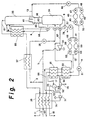
- FIG. 2 is a schematic representation of another preferred embodiment of the method and apparatus of this invention.
- feed air 1 is cooled by indirect heat exchange in main heat exchanger 30 against return streams.
- the feed air is at a pressure sufficient to vaporize liquid to produce elevated pressure product gas as will be more fully described below.
- the feed air will be at a pressure within the range of from 6.2 to 34.5 bar (90 to 500 pounds per square inch absolute (psia)).
- the feed air is divided into two portions.
- the first portion 4 which may be from 5 to 40 percent of the feed air, is passed through heat exchange means which is a dual product side boiler 31. Air portion 4 is at least partially condensed in dual product side boiler 31 and it may be totally condensed. Air portion 4 is then passed through conduit means to heat exchanger or subcooler 32 wherein it is subcooled and then through valve 33 and as stream 6 into first or higher pressure column 34 which is the higher pressure column of a double column system of an air separation plant.
- Higher pressure column 34 is generally operating at a pressure within the range of from 4.1 to 6.9 bar (60 to 100 psia).
- the second portion 5 of the feed air which may comprise from 50 to 90 percent of the feed air, is turboexpanded through turboexpander 35 to develop refrigeration for the cryogenic separation. Expanded air portion 36 is then passed into higher pressure column 34.
- a portion 3 of the feed air may be cooled by indirect heat exchange through heat exchanger 37 against low pressure nitrogen, passed through valve 38 and passed into higher pressure column 34 as part of stream 6.
- the uncondensed part may be used to carry out the heat exchange in heat exchanger 37 instead of or in addition to portion 3.
- Oxygen-enriched liquid is passed 9 through conduit means to heat exchanger 66 wherein it is cooled by indirect heat exchange with low pressure nitrogen and then passed into second or lower pressure column 39, which is operating at a pressure less than that at which higher pressure column 34 is operating, and generally within the range of from 1.0 to 2.1 bar (15 to 30 psia).
- Nitrogen-enriched vapor is passed 40 through conduit means from higher pressure column 34 to condenser/reboiler 41 wherein it is condensed by indirect heat exchange with column 39 bottoms. Condenser/reboiler 41 is preferably within lower pressure column 39 although it may also be outside the column.
- Resulting nitrogen-enriched liquid 42 is passed out of condenser/reboiler 41 and a portion 43 is returned to higher pressure column 34 as reflux.
- Nitrogen-enriched liquid is passed 8 from higher pressure column 34 through heat exchanger 66 and into lower pressure column 39.
- a portion of liquid 42 could be passed as reflux to lower pressure column 39 instead of stream 8 from higher pressure column 34.
- a portion 13 of the oxygen-rich liquid is removed from lower pressure column 39 and is passed to dual product side boiler 31.
- the oxygen-rich liquid is pressurized and thus is vaporized at elevated pressure in the dual product side boiler to produce elevated pressure oxygen gas product.
- oxygen-rich liquid 13 is passed through valve 44 into at least one tank.
- the oxygen-rich liquid is passed into either or both of tanks 45 and 46 through valves 47 and 48 respectively and then through valves 49 and 50 respectively and through valve 51 and as stream 14 to subcooler 32.
- the tank or tanks serve to store product liquid oxygen for later delivery as product oxygen.
- the tank or tanks may be equipped with a pressure building coil or other means to raise the pressure of the oxygen-rich liquid.
- the pressure of the oxygen-rich liquid may be increased by means of a liquid pump or by liquid head, i.e. the height differential between liquid levels.
- the pressurized oxygen-rich liquid is warmed by passage through subcooler 32 and resulting stream 52 is passed to phase separator 53.
- Oxygen-rich liquid 54 is passed from phase separator 53 through dual product side boiler 31 wherein it is partially vaporized and serves to carry out the condensation of the feed air which was discussed above.
- the two phase stream 17 is returned to phase separator 53 and vapor 55 is passed from phase separator 53 through main heat exchanger 30 and is recovered as high pressure oxygen gas product stream 18.
- the high pressure oxygen gas product may have a pressure within the range of from 2.7 to 44.8 bar (40 to 650 psia). Additionally, depending on available system refrigeration, some liquid products may be recovered. For example, liquid oxygen 75 and liquid nitrogen 76 can be produced along with the elevated pressure gas products.
- Nitrogen-enriched liquid is passed from condenser/reboiler 41 to dual product side boiler 31.
- the nitrogen-enriched liquid is pressurized and thus is vaporized at elevated pressure in the dual product side boiler to produce elevated pressure nitrogen gas product.
- nitrogen-enriched liquid is passed 56 through valve 57 into at least one tank.
- the nitrogen-enriched liquid is passed into either or both of tanks 58 and 59 through valves 60 and 61 respectively and then through valves 62 and 63 respectively to subcooler 32.
- the tank or tanks serve to store product liquid nitrogen for later delivery as product nitrogen.
- the tank or tanks may be equipped with a pressure building coil or other means to raise the pressure of the nitrogen-enriched liquid.
- the pressure of the nitrogen-enriched liquid may be increased by means of a liquid pump or liquid head.
- the pressurized nitrogen-enriched liquid 15 is warmed by passage through subcooler 32 and then is vaporized by passage through dual product side boiler 31 wherein it serves to carry out the condensation of the feed air which was discussed above.
- Nitrogen vapor stream 64 is passed through main heat exchanger 30 and is recovered as high pressure nitrogen gas product stream 65.
- the high pressure nitrogen gas product may have a pressure within the range of from 6.9 to 41.4 bar (100 to 600 psia).
- the cryogenic system of this invention can produce nitrogen with a purity of at least 99 percent and up to a purity of 99.99 percent or more, and can produce oxygen with a purity within the range of from 95 to 99.95 percent. If desired some liquid oxygen and/or liquid nitrogen may be recovered directly from the columns without vaporization. Also, if desired, some gaseous oxygen or gaseous nitrogen could be recovered directly from the columns.
- Figure 2 illustrates another embodiment of the invention wherein the first portion of the feed air is turboexpanded prior to passage through the dual product side boiler.
- first portion 70 of the clean, cool, compressed feed air is taken from about the midpoint of main heat exchanger 30 and turboexpanded through turboexpander 71.
- the resulting first feed air portion 72 is then passed through dual product side boiler 31 and heat exchanger 32 and then combined with the second portion of the feed air downstream of turboexpander 35 and passed into higher pressure column 34 as stream 67.
- the additional feed air turboexpansion provides additional refrigeration to the columns thus enabling the production of more liquid products. However the gaseous products would be produced at lower pressures.
- the column internals for either or both of the higher and lower pressure columns may comprise trays or packing. If packing is used the packing may be either random or structured packing. However the invention is particularly suited for use with structured packing column internals. This is because packing will reduce the operating pressures in the columns, helping to improve product recoveries and increase liquid production. Additional stages can be added to packed columns without significantly increasing the operating pressure of the column. Structured packing is preferred over random packing because its performance is more predictable and more stages can be attained in a given bed height. This is important to the first cost and complexity of the system.
- Table I lists a summary of a computer simulation of the invention carried out with the embodiment illustrated in Figure 1.
- the data in Table I is presented for illustrative purposes and is not intended to be limiting.
- the stream numbers in Table I correspond to those of Figure 1.
Description

Claims (15)
- A method for the cryogenic separation of air to produce oxygen and nitrogen comprising:(A) cooling feed air (1) in a main heat exchanger (30) by indirect heat exchange with oxygen gas (55) and nitrogen gas (64) to produce product oxygen gas (18) and product nitrogen gas (65), dividing the cooled feed air into a product boiler portion (4, 72) and a turboexpansion portion (5), turboexpanding (35) the turboexpansion portion (5), passing the turboexpanded portion (36) of the feed air and the product boiler portion (4, 72) of the feed air into a higher pressure column (34) and separating the feed air in the higher pressure column into nitrogen-enriched vapor (40) and oxygen-enriched liquid (9);(B) passing oxygen-enriched liquid (9) from the higher pressure column (34) into a lower pressure column (39);(C) condensing nitrogen-enriched vapor (40) to produce nitrogen-enriched liquid (42) and passing nitrogen-enriched liquid (8) into the lower pressure column (39):(D) separating the fluids (8, 9) passed into the lower pressure column (39) into nitrogen-rich vapor (10) and oxygen-rich liquid (13);(E) removing oxygen-rich liquid (13) from the lower pressure column (39), increasing the pressure of said removed oxygen-rich liquid, warming the elevated pressure oxygen-rich liquid (14) by passing it in indirect heat exchange in a subcooler (32) with the product boiler portion (4, 72) of the feed air cooled in the main heat exchanger (30) and further cooled in a dual product side boiler (31), passing the resulting warmed oxygen-rich liquid (52) to a phase separator (53) and passing oxygen-rich liquid (54) from the phase separator in indirect heat exchange in the dual product side boiler (31) with the product boiler portion (4, 72) of the feed air cooled in the main heat exchanger (30) to partially vaporize the oxygen-rich liquid (54) from the phase separator and to produce a two phase stream (17), passing the two phase stream (17) to the phase separator (53). separating in the phase separator (53) the two phase stream (17) into oxygen-rich vapor (55) and said oxygen-rich liquid (54); passing oxygen-rich vapor (55) from the phase separator (53) through the main heat exchanger (30) to produce oxygen product gas (18); and(F) removing nitrogen-enriched liquid (56) produced by the condensation of nitrogen-enriched vapor in step (C) against oxygen-rich liquid, increasing the pressure of said removed nitrogen-enriched liquid, warming the elevated pressure nitrogen-enriched liquid (15) by passing it in indirect heat exchange in the subcooler (32) with the product boiler portion (4, 72) of the feed air cooled in the main heat exchanger (30) and further cooled in the dual product side boiler (31), passing resulting warmed nitrogen-enriched liquid in indirect heat exchange in the dual product side boiler (31) with the product boiler portion (4, 72) of the feed air cooled in the main heat exchanger (30) to produce nitrogen gas (64), and passing nitrogen vapor (64) from the dual product side boiler (31) through the main heat exchanger (30) to produce nitrogen product gas (65), wherein the product boiler portion (4. 72) of the cooled feed air is at least partly condensed by the heat exchange in said dual product side boiler (31).
- The method of claim 1 wherein the product boiler portion (4. 72) of the cooled feed air is totally condensed by the heat exchange in said dual product side boiler (31).
- The method of claim 1 or 2 wherein the product boiler portion (72) of the cooled feed air is turboexpanded prior to the heat exchange of steps (E) and (F).
- The method of any one of the preceding claims further comprising recovering nitrogen rich vapor (10) taken from the lower pressure column (39).
- The method of any one of the preceding claims wherein the nitrogen-enriched vapor (40) is condensed by indirect exchange with oxygen-rich liquid.
- The method of any one of the preceding claims further comprising recovering some oxygen-rich liquid (75).
- The method of any one of the preceding claims further comprising recovering some nitrogen-enriched liquid (76).
- An apparatus for the cryogenic separation of air to produce oxygen and nitrogen by the process of claim 1, comprising:a main heat exchanger (30) for cooling feed air (1) by indirect heat exchange with oxygen gas (55) and nitrogen gas (64) to produce product oxygen gas (18) and product nitrogen gas (65);means for dividing the cooled feed air into a product boiler portion (4, 72) and a turboexpansion portion (5);a turboexpander (35) for turboexpanding the turboexpansion portion (5);a higher pressure column (34) for separating feed air (5. 4, 72) introduced into the higher pressure column into nitrogen-enriched vapor (40) and oxygen-enriched liquid (9), said turboexpander (35) being in flow communication with the higher pressure column (34);a lower pressure column (39) for separating the fluids (8, 9) passed into the lower pressure column into nitrogen-rich vapor (10) and oxygen-rich liquid (13);conduit means for passing oxygen-enriched liquid (9) from the higher pressure column (34) into the lower pressure column (39);a condenser/reboiler (41) for condensing nitrogen-enriched vapor (40) against oxygen-rich liquid to produce nitrogen-enriched liquid (42);conduit means for passing nitrogen-enriched liquid (8) into the lower pressure column (39);conduit means for removing oxygen-rich liquid (13) from the lower pressure column (39) and means for increasing the pressure of said removed oxygen-rich liquid;conduit means for removing nitrogen-enriched liquid (56) from the condenser/reboiler (41) and means for increasing the pressure of said removed nitrogen-enriched liquid;a dual product side boiler (31), a subcooler (32) and a phase separator (53);said subcooler (32) being connected to receive said elevated pressure oxygen-rich liquid (14) and said elevated pressure nitrogen-enriched liquid (15), and to receive the product boiler portion (4, 72) of the feed air from the dual product side boiler (31), said subcooler (32) being arranged to pass the elevated pressure oxygen-rich liquid (14) and the elevated pressure nitrogen-enriched liquid (15) in indirect heat exchange with the product boiler portion of the feed air from the dual product side boiler (31) for warming the elevated pressure oxygen-rich liquid (14) and the elevated pressure nitrogen-enriched liquid (15) and for subcooling the product boiler portion (4, 72) of the feed air from the dual product side boiler (31);conduit means for passing the two phase oxygen-rich stream (17) from the dual product side boiler (31) to the phase separator (53);conduit means for passing oxygen-rich liquid (54) from the phase separator (53) to the dual product side boiler (31);conduit means for passing the warmed elevated pressure oxygen-rich liquid (52) from the subcooler (32) to the phase separator (53);said dual product side boiler (31) being connected to receive the product boiler portion (4, 72) of the feed air from the main heat exchanger (30), to receive oxygen-rich liquid (54) from the phase separator (53), and to receive the elevated pressure nitrogen-enriched liquid (15) warmed in the subcooler (32), said dual product side boiler (31) being arranged to pass the oxygen-rich liquid (54) from thephase separator (53) and the elevated pressure nitrogen-enriched liquid (15) in indirect heat exchange with the product boiler portion (4, 72) of the feed air from the main heat exchanger (30) to produce a two phase oxygen-rich stream (17) and nitrogen vapor (64) and to at least partially condense the product boiler portion (4, 72) of the feed air;conduit means for passing the subcooled product boiler portion of the feed air from said subcooler (32) to said higher pressure column (34);conduit means for passing oxygen vapor (55) from the phase separator (53) to the main heat exchanger (30); andconduit means for passing nitrogen vapor (64) from the dual product side boiler (31to the main heat exchanger (30).
- The apparatus of claim 8 wherein means provided to pass oxygen-rich liquid (13) from the lower pressure column (39) to the dual product side boiler (31) comprises at least one tank (45, 46).
- The apparatus of claim 8 or 9 wherein means provided to pass nitrogen-enriched liquid (42) from the condenser/reboiler (41) to the dual product side boiler (31) comprises at least one tank (58, 59).
- The apparatus of any one of claims 8 to 10 wherein the means for increasing the pressure of the oxygen-rich liquid removed from the lower pressure column (39) comprises a liquid pump.
- The apparatus of any one of claims 8 to 11 wherein the means for increasing the pressure of the nitrogen-enriched liquid removed from the condenser/reboiler (41) comprises a liquid pump.
- The apparatus of any one of claims 8 to 12 further comprising a turboexpander (71) in flow communication with the dual product side boiler (31).
- The apparatus of any one of claims 8 to 13 wherein at least some of the internals of the higher pressure column (34) comprise structured packing.
- The apparatus of any one of claims 8 to 14 wherein at least some of the internals of the lower pressurc column (39) comprise structured packing.
Applications Claiming Priority (2)
| Application Number | Priority Date | Filing Date | Title |
|---|---|---|---|
| US544641 | 1990-06-27 | ||
| US07/544,641 US5148680A (en) | 1990-06-27 | 1990-06-27 | Cryogenic air separation system with dual product side condenser |
Publications (3)
| Publication Number | Publication Date |
|---|---|
| EP0464630A1 EP0464630A1 (en) | 1992-01-08 |
| EP0464630B1 EP0464630B1 (en) | 1994-08-10 |
| EP0464630B2 true EP0464630B2 (en) | 1998-09-09 |
Family
ID=24172995
Family Applications (1)
| Application Number | Title | Priority Date | Filing Date |
|---|---|---|---|
| EP91110556A Expired - Lifetime EP0464630B2 (en) | 1990-06-27 | 1991-06-26 | Cryogenic air separation with dual product boiler |
Country Status (9)
| Country | Link |
|---|---|
| US (1) | US5148680A (en) |
| EP (1) | EP0464630B2 (en) |
| JP (1) | JPH04227459A (en) |
| KR (1) | KR960003271B1 (en) |
| CN (1) | CN1058644A (en) |
| BR (1) | BR9102694A (en) |
| CA (1) | CA2045739C (en) |
| DE (1) | DE69103347T3 (en) |
| ES (1) | ES2057671T5 (en) |
Families Citing this family (32)
| Publication number | Priority date | Publication date | Assignee | Title |
|---|---|---|---|---|
| JP2909678B2 (en) * | 1991-03-11 | 1999-06-23 | レール・リキード・ソシエテ・アノニム・プール・レテュード・エ・レクスプロワタシオン・デ・プロセデ・ジョルジュ・クロード | Method and apparatus for producing gaseous oxygen under pressure |
| US5228297A (en) * | 1992-04-22 | 1993-07-20 | Praxair Technology, Inc. | Cryogenic rectification system with dual heat pump |
| FR2699992B1 (en) * | 1992-12-30 | 1995-02-10 | Air Liquide | Process and installation for producing gaseous oxygen under pressure. |
| US5303556A (en) * | 1993-01-21 | 1994-04-19 | Praxair Technology, Inc. | Single column cryogenic rectification system for producing nitrogen gas at elevated pressure and high purity |
| FR2701553B1 (en) † | 1993-02-12 | 1995-04-28 | Maurice Grenier | Method and installation for producing oxygen under pressure. |
| US5365741A (en) * | 1993-05-13 | 1994-11-22 | Praxair Technology, Inc. | Cryogenic rectification system with liquid oxygen boiler |
| US5355682A (en) * | 1993-09-15 | 1994-10-18 | Air Products And Chemicals, Inc. | Cryogenic air separation process producing elevated pressure nitrogen by pumped liquid nitrogen |
| US5398514A (en) * | 1993-12-08 | 1995-03-21 | Praxair Technology, Inc. | Cryogenic rectification system with intermediate temperature turboexpansion |
| US5386692A (en) * | 1994-02-08 | 1995-02-07 | Praxair Technology, Inc. | Cryogenic rectification system with hybrid product boiler |
| US5396772A (en) * | 1994-03-11 | 1995-03-14 | The Boc Group, Inc. | Atmospheric gas separation method |
| US5406800A (en) * | 1994-05-27 | 1995-04-18 | Praxair Technology, Inc. | Cryogenic rectification system capacity control method |
| US5666823A (en) | 1996-01-31 | 1997-09-16 | Air Products And Chemicals, Inc. | High pressure combustion turbine and air separation system integration |
| US5836175A (en) * | 1997-08-29 | 1998-11-17 | Praxair Technology, Inc. | Dual column cryogenic rectification system for producing nitrogen |
| US5901578A (en) * | 1998-05-18 | 1999-05-11 | Praxair Technology, Inc. | Cryogenic rectification system with integral product boiler |
| FR2800859B1 (en) * | 1999-11-05 | 2001-12-28 | Air Liquide | METHOD AND APPARATUS FOR AIR SEPARATION BY CRYOGENIC DISTILLATION |
| DE10161584A1 (en) * | 2001-12-14 | 2003-06-26 | Linde Ag | Device and method for generating gaseous oxygen under increased pressure |
| US7210312B2 (en) * | 2004-08-03 | 2007-05-01 | Sunpower, Inc. | Energy efficient, inexpensive extraction of oxygen from ambient air for portable and home use |
| US8191386B2 (en) * | 2008-02-14 | 2012-06-05 | Praxair Technology, Inc. | Distillation method and apparatus |
| US9243842B2 (en) | 2008-02-15 | 2016-01-26 | Black & Veatch Corporation | Combined synthesis gas separation and LNG production method and system |
| US10113127B2 (en) * | 2010-04-16 | 2018-10-30 | Black & Veatch Holding Company | Process for separating nitrogen from a natural gas stream with nitrogen stripping in the production of liquefied natural gas |
| US20120036891A1 (en) * | 2010-08-12 | 2012-02-16 | Neil Mark Prosser | Air separation method and apparatus |
| WO2012075266A2 (en) | 2010-12-01 | 2012-06-07 | Black & Veatch Corporation | Ngl recovery from natural gas using a mixed refrigerant |
| CN102538397A (en) * | 2012-01-18 | 2012-07-04 | 开封黄河空分集团有限公司 | Process for making nitrogen by air separation or making nitrogen and simultaneously producing oxygen in attached manner |
| US10139157B2 (en) | 2012-02-22 | 2018-11-27 | Black & Veatch Holding Company | NGL recovery from natural gas using a mixed refrigerant |
| CN105229400B (en) * | 2013-04-25 | 2018-03-27 | 林德股份公司 | The method and air-seperation system of air products are obtained from the air-seperation system with temporary store |
| US10563913B2 (en) | 2013-11-15 | 2020-02-18 | Black & Veatch Holding Company | Systems and methods for hydrocarbon refrigeration with a mixed refrigerant cycle |
| US9574822B2 (en) | 2014-03-17 | 2017-02-21 | Black & Veatch Corporation | Liquefied natural gas facility employing an optimized mixed refrigerant system |
| JP6738126B2 (en) * | 2015-02-03 | 2020-08-12 | エア・ウォーター・クライオプラント株式会社 | Air separation device |
| WO2017105191A1 (en) * | 2015-12-16 | 2017-06-22 | Velez De La Rocha Martin | Air separation process |
| EP3193114B1 (en) * | 2016-01-14 | 2019-08-21 | Linde Aktiengesellschaft | Method for obtaining an air product in an air separation assembly and air separation assembly |
| CN108529804A (en) * | 2018-04-24 | 2018-09-14 | 浙江荣凯科技发展有限公司 | A kind of dichloro-nicotinic acid production sewage treatment device |
| CN114846287A (en) | 2019-12-23 | 2022-08-02 | 林德有限责任公司 | Method and apparatus for providing an oxygen product |
Family Cites Families (18)
| Publication number | Priority date | Publication date | Assignee | Title |
|---|---|---|---|---|
| US2712738A (en) * | 1952-01-10 | 1955-07-12 | Linde S Eismaschinen Ag | Method for fractionating air by liquefaction and rectification |
| BE547614A (en) * | 1955-05-31 | |||
| US3269130A (en) * | 1957-01-04 | 1966-08-30 | Air Prod & Chem | Separation of gaseous mixtures containing hydrogen and nitrogen |
| US3102801A (en) * | 1957-01-24 | 1963-09-03 | Air Prod & Chem | Low temperature process |
| US3059440A (en) * | 1960-01-19 | 1962-10-23 | John J Loporto | Fluid transfer arrangement |
| DE1112997B (en) * | 1960-08-13 | 1961-08-24 | Linde Eismasch Ag | Process and device for gas separation by rectification at low temperature |
| DE1117616B (en) * | 1960-10-14 | 1961-11-23 | Linde Eismasch Ag | Method and device for obtaining particularly pure decomposition products in cryogenic gas separation plants |
| GB1325881A (en) * | 1969-08-12 | 1973-08-08 | Union Carbide Corp | Cryogenic separation of air |
| GB1314347A (en) * | 1970-03-16 | 1973-04-18 | Air Prod Ltd | Air rectification process for the production of oxygen |
| DE3018476C2 (en) * | 1979-05-16 | 1984-10-25 | Hitachi, Ltd., Tokio/Tokyo | Process and plant for the production of gaseous nitrogen |
| FR2461906A1 (en) * | 1979-07-20 | 1981-02-06 | Air Liquide | CRYOGENIC AIR SEPARATION METHOD AND INSTALLATION WITH OXYGEN PRODUCTION AT HIGH PRESSURE |
| US4345925A (en) * | 1980-11-26 | 1982-08-24 | Union Carbide Corporation | Process for the production of high pressure oxygen gas |
| JPS60142183A (en) * | 1983-12-28 | 1985-07-27 | 日本酸素株式会社 | Method of liquefying and separating air |
| US4560398A (en) * | 1984-07-06 | 1985-12-24 | Union Carbide Corporation | Air separation process to produce elevated pressure oxygen |
| US4704147A (en) * | 1986-08-20 | 1987-11-03 | Air Products And Chemicals, Inc. | Dual air pressure cycle to produce low purity oxygen |
| US4836836A (en) * | 1987-12-14 | 1989-06-06 | Air Products And Chemicals, Inc. | Separating argon/oxygen mixtures using a structured packing |
| US4871382A (en) * | 1987-12-14 | 1989-10-03 | Air Products And Chemicals, Inc. | Air separation process using packed columns for oxygen and argon recovery |
| US4895583A (en) * | 1989-01-12 | 1990-01-23 | The Boc Group, Inc. | Apparatus and method for separating air |
-
1990
- 1990-06-27 US US07/544,641 patent/US5148680A/en not_active Expired - Fee Related
-
1991
- 1991-06-26 KR KR1019910010626A patent/KR960003271B1/en not_active IP Right Cessation
- 1991-06-26 BR BR919102694A patent/BR9102694A/en not_active IP Right Cessation
- 1991-06-26 CN CN91105316A patent/CN1058644A/en active Pending
- 1991-06-26 JP JP3180503A patent/JPH04227459A/en active Pending
- 1991-06-26 ES ES91110556T patent/ES2057671T5/en not_active Expired - Lifetime
- 1991-06-26 DE DE69103347T patent/DE69103347T3/en not_active Expired - Fee Related
- 1991-06-26 CA CA002045739A patent/CA2045739C/en not_active Expired - Fee Related
- 1991-06-26 EP EP91110556A patent/EP0464630B2/en not_active Expired - Lifetime
Also Published As
| Publication number | Publication date |
|---|---|
| EP0464630A1 (en) | 1992-01-08 |
| DE69103347T2 (en) | 1995-03-16 |
| CA2045739C (en) | 1994-05-17 |
| DE69103347T3 (en) | 1999-02-25 |
| KR920000363A (en) | 1992-01-29 |
| DE69103347D1 (en) | 1994-09-15 |
| US5148680A (en) | 1992-09-22 |
| ES2057671T5 (en) | 1998-11-01 |
| CN1058644A (en) | 1992-02-12 |
| JPH04227459A (en) | 1992-08-17 |
| BR9102694A (en) | 1992-02-04 |
| EP0464630B1 (en) | 1994-08-10 |
| ES2057671T3 (en) | 1994-10-16 |
| CA2045739A1 (en) | 1991-12-28 |
| KR960003271B1 (en) | 1996-03-07 |
Similar Documents
| Publication | Publication Date | Title |
|---|---|---|
| EP0464630B2 (en) | Cryogenic air separation with dual product boiler | |
| EP0464635B1 (en) | Cryogenic air separation with dual feed air side condensers | |
| EP0841524B1 (en) | Cryogenic rectification system with kettle liquid column | |
| US5108476A (en) | Cryogenic air separation system with dual temperature feed turboexpansion | |
| US5765396A (en) | Cryogenic rectification system for producing high pressure nitrogen and high pressure oxygen | |
| US5114452A (en) | Cryogenic air separation system for producing elevated pressure product gas | |
| US5467602A (en) | Air boiling cryogenic rectification system for producing elevated pressure oxygen | |
| EP0169679A2 (en) | Air separation process | |
| US5628207A (en) | Cryogenic Rectification system for producing lower purity gaseous oxygen and high purity oxygen | |
| EP0563800B2 (en) | High recovery cryogenic rectification system | |
| EP1156291A1 (en) | Cryogenic air separation system with split kettle recycle | |
| EP0848218B1 (en) | Cryogenic rectification system for producing lower purity oxygen and higher purity oxygen | |
| US5916262A (en) | Cryogenic rectification system for producing low purity oxygen and high purity oxygen | |
| EP0949472B1 (en) | Serial column cryogenic rectification system for producing high purity nitrogen | |
| EP0824209B1 (en) | Cryogenic side columm rectification system for producing low purity oxygen and high purity nitrogen | |
| US5596886A (en) | Cryogenic rectification system for producing gaseous oxygen and high purity nitrogen | |
| US5386691A (en) | Cryogenic air separation system with kettle vapor bypass | |
| EP0909931A2 (en) | Cryogenic rectification system for producing high pressure oxygen | |
| US5878597A (en) | Cryogenic rectification system with serial liquid air feed | |
| EP0848219B1 (en) | Cryogenic rectification system for producing argon and lower purity oxygen | |
| CA2325754C (en) | Cryogenic system for producing enriched air |
Legal Events
| Date | Code | Title | Description |
|---|---|---|---|
| PUAI | Public reference made under article 153(3) epc to a published international application that has entered the european phase |
Free format text: ORIGINAL CODE: 0009012 |
|
| AK | Designated contracting states |
Kind code of ref document: A1 Designated state(s): BE DE ES FR GB IT NL |
|
| 17P | Request for examination filed |
Effective date: 19920121 |
|
| 17Q | First examination report despatched |
Effective date: 19920720 |
|
| RAP1 | Party data changed (applicant data changed or rights of an application transferred) |
Owner name: PRAXAIR TECHNOLOGY, INC. |
|
| GRAA | (expected) grant |
Free format text: ORIGINAL CODE: 0009210 |
|
| ITF | It: translation for a ep patent filed |
Owner name: BARZANO' E ZANARDO ROMA S.P.A. |
|
| AK | Designated contracting states |
Kind code of ref document: B1 Designated state(s): BE DE ES FR GB IT NL |
|
| REF | Corresponds to: |
Ref document number: 69103347 Country of ref document: DE Date of ref document: 19940915 |
|
| REG | Reference to a national code |
Ref country code: ES Ref legal event code: FG2A Ref document number: 2057671 Country of ref document: ES Kind code of ref document: T3 |
|
| ET | Fr: translation filed | ||
| PLBI | Opposition filed |
Free format text: ORIGINAL CODE: 0009260 |
|
| PLBI | Opposition filed |
Free format text: ORIGINAL CODE: 0009260 |
|
| PGFP | Annual fee paid to national office [announced via postgrant information from national office to epo] |
Ref country code: NL Payment date: 19950522 Year of fee payment: 5 |
|
| 26 | Opposition filed |
Opponent name: L'AIR LIQUIDE, S.A. POUR L'ETUDE ET L'EXPLOITATION Effective date: 19950502 |
|
| 26 | Opposition filed |
Opponent name: LINDE AKTIENGESELLSCHAFT Effective date: 19950510 Opponent name: L'AIR LIQUIDE, S.A. POUR L'ETUDE ET L'EXPLOITATION Effective date: 19950502 |
|
| NLR1 | Nl: opposition has been filed with the epo |
Opponent name: LINDE AKTIENGESELLSCHAFT Opponent name: L'AIR LIQUIDE, S.A. POUR L'ETUDE ET L'EXPLOITATION |
|
| PLBF | Reply of patent proprietor to notice(s) of opposition |
Free format text: ORIGINAL CODE: EPIDOS OBSO |
|
| PLBF | Reply of patent proprietor to notice(s) of opposition |
Free format text: ORIGINAL CODE: EPIDOS OBSO |
|
| PG25 | Lapsed in a contracting state [announced via postgrant information from national office to epo] |
Ref country code: NL Effective date: 19970101 |
|
| NLV4 | Nl: lapsed or anulled due to non-payment of the annual fee |
Effective date: 19970101 |
|
| PLAW | Interlocutory decision in opposition |
Free format text: ORIGINAL CODE: EPIDOS IDOP |
|
| PLAW | Interlocutory decision in opposition |
Free format text: ORIGINAL CODE: EPIDOS IDOP |
|
| PGFP | Annual fee paid to national office [announced via postgrant information from national office to epo] |
Ref country code: ES Payment date: 19980617 Year of fee payment: 8 |
|
| PUAH | Patent maintained in amended form |
Free format text: ORIGINAL CODE: 0009272 |
|
| STAA | Information on the status of an ep patent application or granted ep patent |
Free format text: STATUS: PATENT MAINTAINED AS AMENDED |
|
| ITF | It: translation for a ep patent filed |
Owner name: BARZANO' E ZANARDO ROMA S.P.A. |
|
| 27A | Patent maintained in amended form |
Effective date: 19980909 |
|
| AK | Designated contracting states |
Kind code of ref document: B2 Designated state(s): BE DE ES FR GB IT NL |
|
| REG | Reference to a national code |
Ref country code: ES Ref legal event code: DC2A Kind code of ref document: T5 Effective date: 19980923 |
|
| ET3 | Fr: translation filed ** decision concerning opposition | ||
| PGFP | Annual fee paid to national office [announced via postgrant information from national office to epo] |
Ref country code: FR Payment date: 19990601 Year of fee payment: 9 |
|
| PGFP | Annual fee paid to national office [announced via postgrant information from national office to epo] |
Ref country code: GB Payment date: 19990602 Year of fee payment: 9 |
|
| PGFP | Annual fee paid to national office [announced via postgrant information from national office to epo] |
Ref country code: DE Payment date: 19990603 Year of fee payment: 9 |
|
| PGFP | Annual fee paid to national office [announced via postgrant information from national office to epo] |
Ref country code: BE Payment date: 19990624 Year of fee payment: 9 |
|
| PG25 | Lapsed in a contracting state [announced via postgrant information from national office to epo] |
Ref country code: GB Free format text: LAPSE BECAUSE OF NON-PAYMENT OF DUE FEES Effective date: 20000626 |
|
| PG25 | Lapsed in a contracting state [announced via postgrant information from national office to epo] |
Ref country code: ES Free format text: THE PATENT HAS BEEN ANNULLED BY A DECISION OF A NATIONAL AUTHORITY Effective date: 20000627 |
|
| PG25 | Lapsed in a contracting state [announced via postgrant information from national office to epo] |
Ref country code: BE Free format text: LAPSE BECAUSE OF NON-PAYMENT OF DUE FEES Effective date: 20000630 |
|
| BERE | Be: lapsed |
Owner name: PRAXAIR TECHNOLOGY INC. Effective date: 20000630 |
|
| GBPC | Gb: european patent ceased through non-payment of renewal fee |
Effective date: 20000626 |
|
| PG25 | Lapsed in a contracting state [announced via postgrant information from national office to epo] |
Ref country code: FR Free format text: LAPSE BECAUSE OF NON-PAYMENT OF DUE FEES Effective date: 20010228 |
|
| REG | Reference to a national code |
Ref country code: FR Ref legal event code: ST |
|
| PG25 | Lapsed in a contracting state [announced via postgrant information from national office to epo] |
Ref country code: DE Free format text: LAPSE BECAUSE OF NON-PAYMENT OF DUE FEES Effective date: 20010403 |
|
| REG | Reference to a national code |
Ref country code: ES Ref legal event code: FD2A Effective date: 20020304 |
|
| PG25 | Lapsed in a contracting state [announced via postgrant information from national office to epo] |
Ref country code: IT Free format text: LAPSE BECAUSE OF NON-PAYMENT OF DUE FEES;WARNING: LAPSES OF ITALIAN PATENTS WITH EFFECTIVE DATE BEFORE 2007 MAY HAVE OCCURRED AT ANY TIME BEFORE 2007. THE CORRECT EFFECTIVE DATE MAY BE DIFFERENT FROM THE ONE RECORDED. Effective date: 20050626 |