EP0464431A2 - Coordinate-measuring machine of the standing-axis type - Google Patents
Coordinate-measuring machine of the standing-axis type Download PDFInfo
- Publication number
- EP0464431A2 EP0464431A2 EP91109827A EP91109827A EP0464431A2 EP 0464431 A2 EP0464431 A2 EP 0464431A2 EP 91109827 A EP91109827 A EP 91109827A EP 91109827 A EP91109827 A EP 91109827A EP 0464431 A2 EP0464431 A2 EP 0464431A2
- Authority
- EP
- European Patent Office
- Prior art keywords
- carriage
- stand
- coordinate
- drive
- auxiliary
- Prior art date
- Legal status (The legal status is an assumption and is not a legal conclusion. Google has not performed a legal analysis and makes no representation as to the accuracy of the status listed.)
- Granted
Links
- 230000005484 gravity Effects 0.000 claims abstract description 11
- 238000010276 construction Methods 0.000 claims description 5
- 238000005516 engineering process Methods 0.000 abstract description 2
- 238000006243 chemical reaction Methods 0.000 description 2
- 241001295925 Gegenes Species 0.000 description 1
- 238000006073 displacement reaction Methods 0.000 description 1
- 239000010438 granite Substances 0.000 description 1
- 238000005259 measurement Methods 0.000 description 1
- 239000000523 sample Substances 0.000 description 1
Images


Classifications
-
- G—PHYSICS
- G01—MEASURING; TESTING
- G01B—MEASURING LENGTH, THICKNESS OR SIMILAR LINEAR DIMENSIONS; MEASURING ANGLES; MEASURING AREAS; MEASURING IRREGULARITIES OF SURFACES OR CONTOURS
- G01B5/00—Measuring arrangements characterised by the use of mechanical techniques
- G01B5/0011—Arrangements for eliminating or compensation of measuring errors due to temperature or weight
- G01B5/0016—Arrangements for eliminating or compensation of measuring errors due to temperature or weight due to weight
-
- G—PHYSICS
- G01—MEASURING; TESTING
- G01B—MEASURING LENGTH, THICKNESS OR SIMILAR LINEAR DIMENSIONS; MEASURING ANGLES; MEASURING AREAS; MEASURING IRREGULARITIES OF SURFACES OR CONTOURS
- G01B5/00—Measuring arrangements characterised by the use of mechanical techniques
- G01B5/004—Measuring arrangements characterised by the use of mechanical techniques for measuring coordinates of points
- G01B5/008—Measuring arrangements characterised by the use of mechanical techniques for measuring coordinates of points using coordinate measuring machines
Definitions
- the invention relates to a coordinate measuring machine in stand construction with a stand which can be displaced horizontally in two coordinate directions and which carries a height-adjustable measuring arm.
- the solution described is based on a concept in which the guides for the two coordinate directions are based on one another.
- the drive of the auxiliary slide which is primarily guided in the fixed part with respect to the first coordinate direction, does not act on the auxiliary slide itself, but rather on the slide carried thereon and supporting the stand.
- the auxiliary slide only has to still absorb the drive forces in the X direction, i.e. in the direction in which the stand is guided on it, while it is simply dragged along in the Y direction perpendicular thereto via the guide for the stand attached to it.
- the auxiliary carriage Since the auxiliary carriage has only a relatively small mass, the main mass of the device is formed by the stand itself or the carriage carrying it, a drive for the direction of movement of the auxiliary carriage can therefore be ensured essentially close to or in the center of gravity of the parts to be driven.
- the fixed machine base of the coordinate measuring machine shown in the figures is formed by a machine table (1) consisting, for example, of granite, on which the moving parts of the coordinate measuring machine slide smoothly along guides attached to the table (1) via air bearings.
- the stand which can be moved on the table in two coordinate directions (X and Y) is designated by (10) and has the shape of a rectangular column.
- the vertically movable measuring arm (11) of the device is mounted on this stand (10) and carries at its front end the probe (13) with which the workpiece to be measured (not shown here) is touched.
- the stand (10) is mounted on a carriage (12) which has approximately the shape of a triangular plate and rests at the ends via three air bearings (14a-c) directly on the surface of the machine table (1).
- the carriage (12) which is referred to below as the superstructure, is guided on a guide rail (3) on an auxiliary carriage (2) with respect to the coordinate direction indicated by the arrow (Y).
- Y coordinate direction indicated by the arrow (Y).
- two pairs of air bearings (17a and 17b) braced against each other are provided on the superstructure.
- the guide bar (3) on the undercarriage encompassed by the air bearing pairs (17a, 17b) carries the scale (16) for measuring the displacement of the stand (10) in the Y direction.
- the auxiliary carriage (2) is referred to below as the undercarriage.
- the undercarriage (2) also lies on the machine table (1) via three air bearings, namely the air bearings (4a, b and c) and is in turn on a guide bar (5) on the machine part with respect to the coordinate direction indicated by the arrow (X) (1) performed.
- the Guide bar (5) also carries the scale (6) with which the movement of the undercarriage in the coordinate direction (X) is measured.
- the undercarriage is connected to the guide rail (5), as for the uppercarriage, by means of two pairs of air bearings (7a and 7b) attached to each other and braced against one another.
- the undercarriage is provided with an elongated slot (8) in direction (Y) through which the air bearing (14c) of the superstructure engages.
- a first drive For driving the stand (10) in the X direction, i.e. In the direction in which the undercarriage (2) is guided, a first drive is provided, which is mounted on the superstructure (12) itself.
- This drive consists of a motor (19) and a gear housing (18) and a drive spindle (20).
- the spindle (20) works against a spindle nut, which is supported on the table (1) by means of a connecting element (21) and an air bearing pair (22a / 22b) against an additional auxiliary guide (15).
- the auxiliary guide (15) extends parallel to the guide (3) on the undercarriage (2) in the Y direction.
- the drive (18-21) is positioned so that its line of action (W1) does not essentially pass through the center of gravity designated by (S) of the jointly movable part consisting of the stand (10), measuring arm (11) and superstructure (12) passes exactly because the center of gravity is a little higher vertically than the table level.
- the center of gravity (S) and the line of action (W1) lie in the same vertical plane (V1), so that regardless of the position of the stand (10) along the coordinate (Y) with respect to the vertical axis of the stand (10), it is always driven without torque becomes.
- the relatively light undercarriage (2) is simply carried along by the guide bar (3) encompassed by the air bearings (17a, 17b).
- a corresponding drive (9) is provided for the movement in the Y direction of the stand (10).
- This drive (9) is mounted on the undercarriage and is also arranged with its line of action (W2) in a plane containing the center of gravity (S).
Landscapes
- Physics & Mathematics (AREA)
- General Physics & Mathematics (AREA)
- A Measuring Device Byusing Mechanical Method (AREA)
- Length Measuring Devices With Unspecified Measuring Means (AREA)
Abstract
Die beschriebene Lösung geht wie in der Koordinatenmeßtechnik üblich von einem Konzept aus, bei dem die Führungen für die beiden Koordinatenrichtungen aufeinander aufbauen. Jedoch wirkt der Antrieb des primär bezüglich der ersten Koordinatenrichtung im festen Teil geführten Hilfsschlittens nicht auf diesen selbst, sondern auf den daran geführten, den Ständer tragenden Schlitten. Der Hilfsschlitten muß also nur noch die Antriebskräfte in X-Richtung aufnehmen, also in der Richtung, in der der Ständer an ihm selbst geführt ist, während er in der dazu senkrechten Y-Richtung einfach über die an ihn angebaute Führung für den Ständer mitgeschleppt wird. Da der Hilfsschlitten nur eine relativ geringe Masse besitzt, die Hauptmasse des Gerätes durch den Ständer selbst bzw. den ihn tragenden Schlitten gebildet wird, kann deshalb auch für die Bewegungsrichtung des Hilfsschlittens ein Antrieb im wesentlichen nahe bzw. im Schwerpunkt der anzutreibenden Teile sichergestellt werden.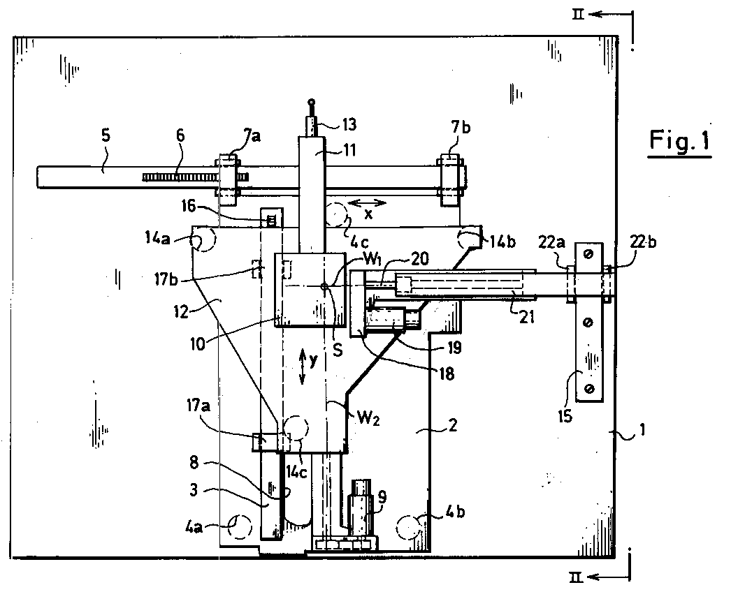
Description
Die Erfindung betrifft ein Koordinatenmeßgerät in Ständerbauweise mit einem in zwei Koordinatenrichtungen waagerecht verschiebbaren Ständer, der einen höhenverstellbaren Meßarm trägt.The invention relates to a coordinate measuring machine in stand construction with a stand which can be displaced horizontally in two coordinate directions and which carries a height-adjustable measuring arm.
Koordinatenmeßgeräte mit diesem Aufbau werden in letzter Zeit verstärkt eingesetzt, da sie sich aufgrund ihrer kompakten Bauweise leicht für den Einsatz unter Fertigungsbedingungen kapseln lassen und wegen des gut zugänglichen Meßbereiches sehr bedienerfreundlich sind.Coordinate measuring machines with this structure have recently been used increasingly, since their compact design means that they can easily be encapsulated for use under production conditions and are very user-friendly because of the easily accessible measuring range.
Bei dieser Bauweise ist es jedoch schwierig, die Meßgeschwindigkeit unter Beibehaltung der erzielbaren Führungsgenauigkeit zu steigern. Denn da der relativ schwere Ständer in zwei Koordinatenrichtungen beweglich ist, treten bei Beschleunigung in einer Richtung abhängig von seiner momentanen Position in der anderen Koordinatenrichtung außerachsiale Reaktionsmomente auf, die auf den Führungen abgestützt werden müssen. Dadurch werden die Führungen stark belastet.With this design, however, it is difficult to increase the measuring speed while maintaining the achievable guiding accuracy. Because the relatively heavy stand can be moved in two coordinate directions, when accelerating in one direction, depending on its current position in the other coordinate direction, non-axial reaction moments occur which have to be supported on the guides. This places a heavy load on the guides.
Es ist aus der DE-PS 27 18 506 bekannt, das Portal von Koordinaten-Meßgeräten in Portalbauweise möglichst nahe an seinem Schwerpunkt anzutreiben, um Verkippungen bzw. Verdrehungen des Portals und daraus resultierende Meßfehler zu vermeiden. Hier ist das Portal selbst jedoch nur in einer Koordinatenrichtung verfahrbar, so daß der Antrieb einfach an einer festen Stelle des Maschinenbettes aufgebaut werden kann. Diese Lösung ist jedoch nicht für den Antrieb eines in zwei Koordinaten gleichzeitig beweglichen Ständers geeignet.It is known from DE-PS 27 18 506 to drive the portal of coordinate measuring machines in portal construction as close as possible to its center of gravity in order to avoid tilting or twisting of the portal and resulting measurement errors. Here, however, the portal itself can only be moved in one coordinate direction, so that the drive can simply be set up at a fixed point on the machine bed. However, this solution is not suitable for driving a stand that can be moved simultaneously in two coordinates.
Aus der DE-PS 36 28 202 ist ein Koordinatenmeßgerät in Brückenbauweise bekannt, bei dem die in zwei Koordinatenrichtungen bewegliche, allerdings relativ leichtgewichtige Pinole bezüglich beider Koordinaten in ihrem Zentrum durch mit ihr gekoppelte Antriebe bewegt wird, die sich auf gegenüberliegenden Seiten der Brückenkonstruktion abstützen. Bei einem solchen, aufgrund des beschriebenen symmetrischen Aufbaues zwar sehr genau und schnell arbeitenden Gerätes, ist der Meßbereich jedoch schlecht zugänglich wegen der vier Säulen, auf der die gesamte Brückenkonstruktion ruht.From DE-PS 36 28 202 a coordinate measuring machine in bridge design is known, in which the two Coordinate directions movable, but relatively light weight quill is moved with respect to both coordinates in its center by drives coupled to it, which are supported on opposite sides of the bridge construction. With such a device, which works very precisely and quickly due to the symmetrical structure described, the measuring range is, however, difficult to access because of the four columns on which the entire bridge construction rests.
Es ist die Aufgabe der vorliegenden Erfindung, bei einem Koordinatenmeßgerät in Ständerbauweise mit einem in zwei Koordinatenrichtungen waagerecht verschiebbaren Ständer Antriebe und Führungen so anzuordnen, daß Belastungen der Führungen aufgrund außerachsialer Momente beim Antrieb in beiden Koordinatenrichtungen weitgehend vermieden sind.It is the object of the present invention to arrange drives and guides in a stator-type coordinate measuring machine with a stand which can be displaced horizontally in two coordinate directions in such a way that loads on the guides due to non-axial moments when driving in both coordinate directions are largely avoided.
Diese Aufgabe wird mit den im Kennzeichen des Anspruchs 1 angegebenen Maßnahmen dadurch gelöst, daß
- der den Ständer tragende Schlitten in einer ersten Koordinatenrichtung an einem Hilfsschlitten geführt ist, der seinerseits bezüglich der zweiten Koordinatenrichtung durch ein erstes Führungselement am feststehenden Teil des Gerätes geführt ist,
- ein erster Antrieb für die Bewegung des Hilfsschlittens an dem den Ständer tragenden Schlitten befestigt ist und am festen Teil eine weitere, parallel zur ersten Koordinatenrichtung ausgerichtete Führung vorgesehen ist, gegen die sich der Antrieb abstützt.
- the carriage carrying the stand is guided in a first coordinate direction on an auxiliary carriage, which in turn is guided by a first guide element on the fixed part of the device with respect to the second coordinate direction,
- a first drive for the movement of the auxiliary slide is fastened to the slide carrying the stand and a further guide is provided on the fixed part, which is oriented parallel to the first coordinate direction and against which the drive is supported.
Die beschriebene Lösung geht wie in der Koordinatenmeßtechnik üblich von einem Konzept aus, bei dem die Führungen für die beiden Koordinatenrichtungen aufeinander aufbauen. Jedoch wirkt der Antrieb des primär bezüglich der ersten Koordinatenrichtung im festen Teil geführten Hilfsschlittens nicht auf diesen selbst, sondern auf den daran geführten, den Ständer tragenden Schlitten. Der Hilfsschlitten muß also nur noch die Antriebskräfte in X-Richtung aufnehmen, also in der Richtung, in der der Ständer an ihm selbst geführt ist, während er in der dazu senkrechten Y-Richtung einfach über die an ihn angebaute Führung für den Ständer mitgeschleppt wird. Da der Hilfsschlitten nur eine relativ geringe Masse besitzt, die Hauptmasse des Gerätes durch den Ständer selbst bzw. den ihn tragenden Schlitten gebildet wird, kann deshalb auch für die Bewegungsrichtung des Hilfsschlittens ein Antrieb im wesentlichen nahe bzw. im Schwerpunkt der anzutreibenden Teile sichergestellt werden.As is customary in coordinate measuring technology, the solution described is based on a concept in which the guides for the two coordinate directions are based on one another. However, the drive of the auxiliary slide, which is primarily guided in the fixed part with respect to the first coordinate direction, does not act on the auxiliary slide itself, but rather on the slide carried thereon and supporting the stand. The auxiliary slide only has to still absorb the drive forces in the X direction, i.e. in the direction in which the stand is guided on it, while it is simply dragged along in the Y direction perpendicular thereto via the guide for the stand attached to it. Since the auxiliary carriage has only a relatively small mass, the main mass of the device is formed by the stand itself or the carriage carrying it, a drive for the direction of movement of the auxiliary carriage can therefore be ensured essentially close to or in the center of gravity of the parts to be driven.
Vorteilhaft im Sinne eines kompakten und die Belastung der Führung reduzierenden Aufbaues ist es, wenn der den Ständer tragende Schlitten direkt auf einer waagerechten Führungsplatte des festen Teils aufliegt. Für den Hilfsschlitten ist dann nur sehr wenig eigene Masse erforderlich, da er nur der Führung des Ständers in einer waagerechten Koordinate dient und nicht das Gewicht des Ständers mitaufnehmen muß.It is advantageous in the sense of a compact structure which reduces the load on the guide if the slide bearing the stand rests directly on a horizontal guide plate of the fixed part. Very little own mass is then required for the auxiliary slide, since it only serves to guide the stand in a horizontal coordinate and does not have to take up the weight of the stand.
Wenn es auch nicht möglich ist, den Antrieb bzw. seine Wirkungslinie exakt in den Schwerpunkt des aus dem Ständer und dem ihn tragenden Schlitten bestehenden Teils des Koordinatenmeßgerätes zu legen, so ist es doch zweckmäßig, die Wirkungslinie des Antriebs in eine Vertikalebene zu legen, die im wesentlichen durch den Schwerpunkt des durch den Antrieb bewegten Teils verläuft. Damit ist sichergestellt, daß keine störenden Reaktionsmomente bezogen auf die vertikale Achse des Ständers auftreten.If it is also not possible to place the drive or its line of action exactly in the center of gravity of the part of the coordinate measuring machine consisting of the stand and the carriage carrying it, it is nevertheless expedient to place the line of action of the drive in a vertical plane which essentially through the center of gravity of the part moved by the drive. This ensures that there are no disruptive reaction moments with respect to the vertical axis of the stator.
Weitere Vorteile der Erfindung ergeben sich aus der nachfolgenden Beschreibung eines Ausführungsbeispiels anhand der Figuren 1 und 2 der beigefügten Zeichnungen.
- Fig. 1
- stellt das erfindungsgemäße Koordinatenmeßgerät bei abgenommener Verkleidung in Aufsicht dar;
- Fig. 2
- ist eine Seitenansicht des Koordinatenmeßgerätes aus Fig. 1.
- Fig. 1
- represents the coordinate measuring machine according to the invention with the cover removed in supervision;
- Fig. 2
- 1 is a side view of the coordinate measuring machine of FIG. 1.
Die feststehende Maschinenbasis des in den Figuren dargestellten Koordinatenmeßgerätes wird durch einen beispielsweise aus Granit bestehenden Maschinentisch (1) gebildet, auf dem die beweglichen Teile des Koordinatenmeßgerätes entlang von an den Tisch (1) angebauten Führungen über Luftlager reibungsfrei gleiten.The fixed machine base of the coordinate measuring machine shown in the figures is formed by a machine table (1) consisting, for example, of granite, on which the moving parts of the coordinate measuring machine slide smoothly along guides attached to the table (1) via air bearings.
Der in zwei Koordinatenrichtungen (X und Y) auf dem Tisch verfahrbare Ständer ist mit (10) bezeichnet und besitzt die Form einer rechteckigen Säule. An diesen Ständer (10) ist der in der Vertikalen verfahrbare Meßarm (11) des Gerätes gelagert, der an seinem vorderen Ende den Tastkopf (13) trägt, mit dem das zu vermessende Werkstück (hier nicht dargestellt) angetastet wird.The stand which can be moved on the table in two coordinate directions (X and Y) is designated by (10) and has the shape of a rectangular column. The vertically movable measuring arm (11) of the device is mounted on this stand (10) and carries at its front end the probe (13) with which the workpiece to be measured (not shown here) is touched.
Der Ständer (10) ist auf einen Schlitten (12) montiert, der etwa die Form einer dreieckigen Platte besitzt und an den Enden über drei Luftlager (14a-c) direkt auf der Oberfläche des Maschinentisches (1) aufliegt. Der Schlitten (12), der nachstehend als Oberwagen bezeichnet wird, ist bezüglich der durch den Pfeil (Y) bezeichneten Koordinatenrichtung an einer Führungsleiste (3) auf einem Hilfsschlitten (2) geführt. Hierfür sind zwei jeweils gegeneinander verspannte Luftlagerpaare (17a und 17b) am Oberwagen vorgesehen. Die von den Luftlagerpaaren (17a, 17b) umgriffene Führungsleiste (3) auf dem Unterwagen trägt den Maßstab (16) zur Messung der Verschiebung des Ständers (10) in Y-Richtung. Der Hilfsschlitten (2) wird nachstehend als Unterwagen bezeichnet. Der Unterwagen (2) liegt ebenfalls über drei Luftlager, nämlich die Luftlager (4a, b und c) auf dem Maschinentisch (1) auf und ist seinerseits bezüglich der mit dem Pfeil (X) bezeichneten Koordinatenrichtung an einer Führungsleiste (5) auf dem Maschinenteil (1) geführt. Die Führungsleiste (5) trägt auch den Maßstab (6), mit dem die Bewegung des Unterwagens in Koordinatenrichtung (X) gemessen wird. Die Anbindung des Unterwagens an die Führungsleiste (5) erfolgt wie für den Oberwagen durch zwei an Umgriffen befestigte, gegeneinander verspannte Luftlagerpaare (7a und 7b).The stand (10) is mounted on a carriage (12) which has approximately the shape of a triangular plate and rests at the ends via three air bearings (14a-c) directly on the surface of the machine table (1). The carriage (12), which is referred to below as the superstructure, is guided on a guide rail (3) on an auxiliary carriage (2) with respect to the coordinate direction indicated by the arrow (Y). For this purpose, two pairs of air bearings (17a and 17b) braced against each other are provided on the superstructure. The guide bar (3) on the undercarriage encompassed by the air bearing pairs (17a, 17b) carries the scale (16) for measuring the displacement of the stand (10) in the Y direction. The auxiliary carriage (2) is referred to below as the undercarriage. The undercarriage (2) also lies on the machine table (1) via three air bearings, namely the air bearings (4a, b and c) and is in turn on a guide bar (5) on the machine part with respect to the coordinate direction indicated by the arrow (X) (1) performed. The Guide bar (5) also carries the scale (6) with which the movement of the undercarriage in the coordinate direction (X) is measured. The undercarriage is connected to the guide rail (5), as for the uppercarriage, by means of two pairs of air bearings (7a and 7b) attached to each other and braced against one another.
Der Unterwagen ist in Richtung (Y) mit einem länglichen Schlitz (8) versehen, durch den das Luftlager (14c) des Oberwagens hindurchgreift.The undercarriage is provided with an elongated slot (8) in direction (Y) through which the air bearing (14c) of the superstructure engages.
Für den Antrieb des Ständers (10) in X-Richtung, d.h. in die Richtung, in der der Unterwagen (2) geführt ist, ist ein erster Antrieb vorgesehen, der auf dem Oberwagen (12) selbst montiert ist. Dieser Antrieb besteht aus einem Motor (19) und einem Getriebegehäuse (18) sowie einer Antriebsspindel (20). Die Spindel (20) arbeitet gegen eine Spindelmutter, die sich über ein Verbindungselement (21) und ein Luftlagerpaar (22a/22b) gegen eine zusätzliche Hilfsführung (15) auf dem Tisch (1) abstützt. Die Hilfsführung (15) erstreckt sich parallel zur Führung (3) auf dem Unterwagen (2) in Y-Richtung. Der Antrieb (18 - 21) ist so positioniert, daß seine Wirkungslinie (W1) im wesentlichen durch den mit (S) bezeichneten Schwerpunkt des aus Ständer (10), Meßarm (11) und Oberwagen (12) bestehenden, gemeinsam beweglichen Teils zwar nicht exakt hindurchgeht, da der Schwerpunkt der in Säule vertikal gesehen etwas höher liegt als die Tischebene. Der Schwerpunkt (S) und die Wirkungslinie (W1) liegen jedoch in der gleichen Vertikalebene (V1), so daß unabhängig von der Position des Ständers (10) entlang der Koordinate (Y) bezogen auf die Vertikalachse des Ständers (10) immer momentenfrei angetrieben wird.For driving the stand (10) in the X direction, i.e. In the direction in which the undercarriage (2) is guided, a first drive is provided, which is mounted on the superstructure (12) itself. This drive consists of a motor (19) and a gear housing (18) and a drive spindle (20). The spindle (20) works against a spindle nut, which is supported on the table (1) by means of a connecting element (21) and an air bearing pair (22a / 22b) against an additional auxiliary guide (15). The auxiliary guide (15) extends parallel to the guide (3) on the undercarriage (2) in the Y direction. The drive (18-21) is positioned so that its line of action (W1) does not essentially pass through the center of gravity designated by (S) of the jointly movable part consisting of the stand (10), measuring arm (11) and superstructure (12) passes exactly because the center of gravity is a little higher vertically than the table level. However, the center of gravity (S) and the line of action (W1) lie in the same vertical plane (V1), so that regardless of the position of the stand (10) along the coordinate (Y) with respect to the vertical axis of the stand (10), it is always driven without torque becomes.
Hierbei wird der relativ leichte Unterwagen (2) über die von den Luftlagern (17a, 17b) umgriffene Führungsleiste (3) einfach mitgenommen.The relatively light undercarriage (2) is simply carried along by the guide bar (3) encompassed by the air bearings (17a, 17b).
Für die Bewegung in Y-Richtung des Ständers (10) ist ein entsprechender Antrieb (9) vorgesehen. Dieser Antrieb (9) ist auf den Unterwagen montiert und mit seiner Wirkungslinie (W2) ebenfalls in einer den Schwerpunkt (S) enthaltenden Ebene angeordnet.A corresponding drive (9) is provided for the movement in the Y direction of the stand (10). This drive (9) is mounted on the undercarriage and is also arranged with its line of action (W2) in a plane containing the center of gravity (S).
Claims (5)
dadurch gekennzeichnet, daß
characterized in that
Applications Claiming Priority (2)
| Application Number | Priority Date | Filing Date | Title |
|---|---|---|---|
| DE9007052U | 1990-06-25 | ||
| DE9007052U DE9007052U1 (en) | 1990-06-25 | 1990-06-25 | Coordinate measuring machine in column design |
Publications (3)
| Publication Number | Publication Date |
|---|---|
| EP0464431A2 true EP0464431A2 (en) | 1992-01-08 |
| EP0464431A3 EP0464431A3 (en) | 1992-09-23 |
| EP0464431B1 EP0464431B1 (en) | 1995-08-09 |
Family
ID=6854895
Family Applications (1)
| Application Number | Title | Priority Date | Filing Date |
|---|---|---|---|
| EP91109827A Expired - Lifetime EP0464431B1 (en) | 1990-06-25 | 1991-06-15 | Coordinate-measuring machine of the standing-axis type |
Country Status (3)
| Country | Link |
|---|---|
| EP (1) | EP0464431B1 (en) |
| JP (1) | JP2556567Y2 (en) |
| DE (2) | DE9007052U1 (en) |
Cited By (1)
| Publication number | Priority date | Publication date | Assignee | Title |
|---|---|---|---|---|
| EP1462760A1 (en) * | 2003-03-24 | 2004-09-29 | Klingelnberg GmbH | Apparatus for measuring the position of a probe in a coordinate measuring machine |
Families Citing this family (5)
| Publication number | Priority date | Publication date | Assignee | Title |
|---|---|---|---|---|
| DE4107471C2 (en) * | 1991-03-08 | 1994-03-17 | Porsche Ag | Device and method for measuring wear and thickness on brake linings of disc brakes |
| DE4126532A1 (en) * | 1991-08-10 | 1993-02-11 | Plath Hans Henning Dr Ing | Three=dimensional coordinate measuring appts. for workpieces - has vertically movable sensing arm, flat base plate forming reference surface, mechanical support and guide |
| DE20002150U1 (en) * | 2000-02-08 | 2001-06-13 | Werth Messtechnik GmbH, 35394 Gießen | Coordinate measuring machine |
| DE20204832U1 (en) * | 2002-03-27 | 2002-06-13 | Hommelwerke GmbH, 78056 Villingen-Schwenningen | Device for measuring the rough and / or fine structure of a surface of a workpiece |
| DE102011085339B4 (en) * | 2011-10-27 | 2013-06-06 | Eitzenberger Luftlagertechnik Gmbh | Positioning device, cross table and lifting unit |
Family Cites Families (4)
| Publication number | Priority date | Publication date | Assignee | Title |
|---|---|---|---|---|
| IT1179305B (en) * | 1984-04-04 | 1987-09-16 | Finike Italiana Marposs | EQUIPMENT FOR MEASURING DIMENSIONS, IN PARTICULAR DIAMETER AND AXIAL DIMENSIONS OF PIECES WITH ROTATION SYMMETRY |
| JPH066248B2 (en) * | 1985-10-14 | 1994-01-26 | オムロン株式会社 | XY stage |
| JPH0632563Y2 (en) * | 1988-05-18 | 1994-08-24 | トヨタ自動車株式会社 | Gate type simple three-dimensional measuring instrument |
| DE3936463A1 (en) * | 1989-11-02 | 1991-05-08 | Zeiss Carl Fa | COORDINATE MEASURING DEVICE |
-
1990
- 1990-06-25 DE DE9007052U patent/DE9007052U1/en not_active Expired - Lifetime
-
1991
- 1991-06-15 DE DE59106199T patent/DE59106199D1/en not_active Expired - Fee Related
- 1991-06-15 EP EP91109827A patent/EP0464431B1/en not_active Expired - Lifetime
- 1991-06-24 JP JP1991047518U patent/JP2556567Y2/en not_active Expired - Fee Related
Cited By (2)
| Publication number | Priority date | Publication date | Assignee | Title |
|---|---|---|---|---|
| EP1462760A1 (en) * | 2003-03-24 | 2004-09-29 | Klingelnberg GmbH | Apparatus for measuring the position of a probe in a coordinate measuring machine |
| US7114265B2 (en) | 2003-03-24 | 2006-10-03 | Klingelnberg Gmbh | Apparatus for detecting the position of a probe element in a multi-coordinate measuring device |
Also Published As
| Publication number | Publication date |
|---|---|
| DE9007052U1 (en) | 1990-08-30 |
| EP0464431B1 (en) | 1995-08-09 |
| JP2556567Y2 (en) | 1997-12-03 |
| DE59106199D1 (en) | 1995-09-14 |
| JPH0488801U (en) | 1992-08-03 |
| EP0464431A3 (en) | 1992-09-23 |
Similar Documents
| Publication | Publication Date | Title |
|---|---|---|
| DE3625193C2 (en) | ||
| DE4226072C2 (en) | Two-dimensional drive system | |
| EP0106033A2 (en) | Feeler head for two or more coordinates measurement | |
| DE4132333C2 (en) | Coordinate measuring device | |
| DE3602549A1 (en) | DEVICE FOR CARRYING HORIZONTAL AND VERTICALLY ADJUSTABLE INFORMATION DEVICES | |
| EP1108974B1 (en) | Coordinate measuring machine | |
| EP0464431B1 (en) | Coordinate-measuring machine of the standing-axis type | |
| DE3704952C2 (en) | ||
| DE69305523T2 (en) | DEVICE FOR DETERMINING THE STEERING GAME AND MEASURING THE STEERING ANGLE OF MOTOR VEHICLES | |
| DE3150978A1 (en) | PORTAL DESIGN MEASURING MACHINE | |
| DE10061883A1 (en) | A drilling or milling machine tool has a work turntable and operating tools on arms pivoting about centers outside the turntable perimeter positioned by polar coordinates | |
| EP1738134B1 (en) | Co-ordinate measurement appliance for measuring the co-ordinates of test objects | |
| DE3440786C2 (en) | ||
| EP0779126B1 (en) | Machine tool with several drive units | |
| DE2631960A1 (en) | SPECIAL CARRIER FOR A SHIFT TRANSDUCER | |
| DE2420981C3 (en) | Coordinate measuring machine | |
| DE3503300A1 (en) | Milling machine | |
| EP1059065A1 (en) | Equipment for X-ray examination | |
| DE2461948C3 (en) | Device for supporting stands on a portal machine tool, in particular a portal grinding machine | |
| DE4141258C2 (en) | Lifting device, in particular for a test facility | |
| DE3412848A1 (en) | Manipulating appliance | |
| DE2409959A1 (en) | DEVICE FOR CONTINUOUS MOVEMENT OF A MECHANICAL ORGAN, AND MACHINERY EQUIPPED WITH IT | |
| DE3131511C2 (en) | ||
| DE102006034455A1 (en) | Positionable workpiece support for a machine and processing system with a corresponding workpiece support | |
| DE3686354T2 (en) | GUIDE ARRANGEMENT OF A MACHINE TOOL FOR THE MORE ACCURATE EFFECT OF THE MACHINE. |
Legal Events
| Date | Code | Title | Description |
|---|---|---|---|
| PUAI | Public reference made under article 153(3) epc to a published international application that has entered the european phase |
Free format text: ORIGINAL CODE: 0009012 |
|
| AK | Designated contracting states |
Kind code of ref document: A2 Designated state(s): DE FR GB IT NL SE |
|
| PUAL | Search report despatched |
Free format text: ORIGINAL CODE: 0009013 |
|
| AK | Designated contracting states |
Kind code of ref document: A3 Designated state(s): DE FR GB IT NL SE |
|
| 17P | Request for examination filed |
Effective date: 19930313 |
|
| 17Q | First examination report despatched |
Effective date: 19940331 |
|
| ITF | It: translation for a ep patent filed | ||
| GRAA | (expected) grant |
Free format text: ORIGINAL CODE: 0009210 |
|
| AK | Designated contracting states |
Kind code of ref document: B1 Designated state(s): DE FR GB IT NL SE |
|
| PG25 | Lapsed in a contracting state [announced via postgrant information from national office to epo] |
Ref country code: NL Free format text: LAPSE BECAUSE OF FAILURE TO SUBMIT A TRANSLATION OF THE DESCRIPTION OR TO PAY THE FEE WITHIN THE PRESCRIBED TIME-LIMIT Effective date: 19950809 |
|
| REF | Corresponds to: |
Ref document number: 59106199 Country of ref document: DE Date of ref document: 19950914 |
|
| GBT | Gb: translation of ep patent filed (gb section 77(6)(a)/1977) |
Effective date: 19951002 |
|
| PG25 | Lapsed in a contracting state [announced via postgrant information from national office to epo] |
Ref country code: SE Effective date: 19951109 |
|
| ET | Fr: translation filed | ||
| NLV1 | Nl: lapsed or annulled due to failure to fulfill the requirements of art. 29p and 29m of the patents act | ||
| PLBE | No opposition filed within time limit |
Free format text: ORIGINAL CODE: 0009261 |
|
| STAA | Information on the status of an ep patent application or granted ep patent |
Free format text: STATUS: NO OPPOSITION FILED WITHIN TIME LIMIT |
|
| 26N | No opposition filed | ||
| REG | Reference to a national code |
Ref country code: GB Ref legal event code: IF02 |
|
| PGFP | Annual fee paid to national office [announced via postgrant information from national office to epo] |
Ref country code: GB Payment date: 20030530 Year of fee payment: 13 |
|
| PGFP | Annual fee paid to national office [announced via postgrant information from national office to epo] |
Ref country code: DE Payment date: 20030603 Year of fee payment: 13 |
|
| PGFP | Annual fee paid to national office [announced via postgrant information from national office to epo] |
Ref country code: FR Payment date: 20030611 Year of fee payment: 13 |
|
| PG25 | Lapsed in a contracting state [announced via postgrant information from national office to epo] |
Ref country code: GB Free format text: LAPSE BECAUSE OF NON-PAYMENT OF DUE FEES Effective date: 20040615 |
|
| PG25 | Lapsed in a contracting state [announced via postgrant information from national office to epo] |
Ref country code: DE Free format text: LAPSE BECAUSE OF NON-PAYMENT OF DUE FEES Effective date: 20050101 |
|
| GBPC | Gb: european patent ceased through non-payment of renewal fee |
Effective date: 20040615 |
|
| PG25 | Lapsed in a contracting state [announced via postgrant information from national office to epo] |
Ref country code: FR Free format text: LAPSE BECAUSE OF NON-PAYMENT OF DUE FEES Effective date: 20050228 |
|
| REG | Reference to a national code |
Ref country code: FR Ref legal event code: ST |
|
| PG25 | Lapsed in a contracting state [announced via postgrant information from national office to epo] |
Ref country code: IT Free format text: LAPSE BECAUSE OF NON-PAYMENT OF DUE FEES;WARNING: LAPSES OF ITALIAN PATENTS WITH EFFECTIVE DATE BEFORE 2007 MAY HAVE OCCURRED AT ANY TIME BEFORE 2007. THE CORRECT EFFECTIVE DATE MAY BE DIFFERENT FROM THE ONE RECORDED. Effective date: 20050615 |