EP0464412A1 - Pneumatical suspension with longitudinal arms - Google Patents
Pneumatical suspension with longitudinal arms Download PDFInfo
- Publication number
- EP0464412A1 EP0464412A1 EP91109585A EP91109585A EP0464412A1 EP 0464412 A1 EP0464412 A1 EP 0464412A1 EP 91109585 A EP91109585 A EP 91109585A EP 91109585 A EP91109585 A EP 91109585A EP 0464412 A1 EP0464412 A1 EP 0464412A1
- Authority
- EP
- European Patent Office
- Prior art keywords
- vehicle frame
- air
- bearing
- guide tube
- crank axle
- Prior art date
- Legal status (The legal status is an assumption and is not a legal conclusion. Google has not performed a legal analysis and makes no representation as to the accuracy of the status listed.)
- Granted
Links
- 239000000725 suspension Substances 0.000 title claims abstract description 22
- 239000003381 stabilizer Substances 0.000 claims description 5
- 230000001419 dependent effect Effects 0.000 claims description 3
- 238000005452 bending Methods 0.000 description 5
- 238000009434 installation Methods 0.000 description 3
- 238000013022 venting Methods 0.000 description 2
- 230000000694 effects Effects 0.000 description 1
- 238000009423 ventilation Methods 0.000 description 1
Images


Classifications
-
- B—PERFORMING OPERATIONS; TRANSPORTING
- B60—VEHICLES IN GENERAL
- B60G—VEHICLE SUSPENSION ARRANGEMENTS
- B60G7/00—Pivoted suspension arms; Accessories thereof
- B60G7/02—Attaching arms to sprung part of vehicle
-
- B—PERFORMING OPERATIONS; TRANSPORTING
- B60—VEHICLES IN GENERAL
- B60G—VEHICLE SUSPENSION ARRANGEMENTS
- B60G11/00—Resilient suspensions characterised by arrangement, location or kind of springs
- B60G11/32—Resilient suspensions characterised by arrangement, location or kind of springs having springs of different kinds
- B60G11/48—Resilient suspensions characterised by arrangement, location or kind of springs having springs of different kinds not including leaf springs
- B60G11/64—Resilient suspensions characterised by arrangement, location or kind of springs having springs of different kinds not including leaf springs having both torsion-bar springs and fluid springs
-
- B—PERFORMING OPERATIONS; TRANSPORTING
- B60—VEHICLES IN GENERAL
- B60G—VEHICLE SUSPENSION ARRANGEMENTS
- B60G17/00—Resilient suspensions having means for adjusting the spring or vibration-damper characteristics, for regulating the distance between a supporting surface and a sprung part of vehicle or for locking suspension during use to meet varying vehicular or surface conditions, e.g. due to speed or load
- B60G17/02—Spring characteristics, e.g. mechanical springs and mechanical adjusting means
- B60G17/027—Mechanical springs regulated by fluid means
- B60G17/0277—Mechanical springs regulated by fluid means the mechanical spring being a torsion spring
-
- B—PERFORMING OPERATIONS; TRANSPORTING
- B60—VEHICLES IN GENERAL
- B60G—VEHICLE SUSPENSION ARRANGEMENTS
- B60G3/00—Resilient suspensions for a single wheel
- B60G3/02—Resilient suspensions for a single wheel with a single pivoted arm
- B60G3/12—Resilient suspensions for a single wheel with a single pivoted arm the arm being essentially parallel to the longitudinal axis of the vehicle
- B60G3/14—Resilient suspensions for a single wheel with a single pivoted arm the arm being essentially parallel to the longitudinal axis of the vehicle the arm being rigid
-
- B—PERFORMING OPERATIONS; TRANSPORTING
- B60—VEHICLES IN GENERAL
- B60G—VEHICLE SUSPENSION ARRANGEMENTS
- B60G2200/00—Indexing codes relating to suspension types
- B60G2200/10—Independent suspensions
- B60G2200/13—Independent suspensions with longitudinal arms only
- B60G2200/132—Independent suspensions with longitudinal arms only with a single trailing arm
-
- B—PERFORMING OPERATIONS; TRANSPORTING
- B60—VEHICLES IN GENERAL
- B60G—VEHICLE SUSPENSION ARRANGEMENTS
- B60G2202/00—Indexing codes relating to the type of spring, damper or actuator
- B60G2202/10—Type of spring
- B60G2202/13—Torsion spring
- B60G2202/134—Torsion spring comprising a transversal torsion bar and/or tube
-
- B—PERFORMING OPERATIONS; TRANSPORTING
- B60—VEHICLES IN GENERAL
- B60G—VEHICLE SUSPENSION ARRANGEMENTS
- B60G2202/00—Indexing codes relating to the type of spring, damper or actuator
- B60G2202/10—Type of spring
- B60G2202/13—Torsion spring
- B60G2202/135—Stabiliser bar and/or tube
-
- B—PERFORMING OPERATIONS; TRANSPORTING
- B60—VEHICLES IN GENERAL
- B60G—VEHICLE SUSPENSION ARRANGEMENTS
- B60G2202/00—Indexing codes relating to the type of spring, damper or actuator
- B60G2202/10—Type of spring
- B60G2202/15—Fluid spring
- B60G2202/152—Pneumatic spring
-
- B—PERFORMING OPERATIONS; TRANSPORTING
- B60—VEHICLES IN GENERAL
- B60G—VEHICLE SUSPENSION ARRANGEMENTS
- B60G2204/00—Indexing codes related to suspensions per se or to auxiliary parts
- B60G2204/40—Auxiliary suspension parts; Adjustment of suspensions
- B60G2204/47—Means for retracting the suspension
- B60G2204/4702—Means for retracting the suspension pneumatically
-
- B—PERFORMING OPERATIONS; TRANSPORTING
- B60—VEHICLES IN GENERAL
- B60G—VEHICLE SUSPENSION ARRANGEMENTS
- B60G2300/00—Indexing codes relating to the type of vehicle
- B60G2300/02—Trucks; Load vehicles
-
- B—PERFORMING OPERATIONS; TRANSPORTING
- B60—VEHICLES IN GENERAL
- B60G—VEHICLE SUSPENSION ARRANGEMENTS
- B60G2300/00—Indexing codes relating to the type of vehicle
- B60G2300/04—Trailers
-
- B—PERFORMING OPERATIONS; TRANSPORTING
- B60—VEHICLES IN GENERAL
- B60G—VEHICLE SUSPENSION ARRANGEMENTS
- B60G2300/00—Indexing codes relating to the type of vehicle
- B60G2300/22—Perambulators
-
- B—PERFORMING OPERATIONS; TRANSPORTING
- B60—VEHICLES IN GENERAL
- B60G—VEHICLE SUSPENSION ARRANGEMENTS
- B60G2300/00—Indexing codes relating to the type of vehicle
- B60G2300/38—Low or lowerable bed vehicles
Definitions
- the invention relates to an air-sprung crank axle for motor vehicles and trailers with longitudinal links pivotably mounted in an axle guide tube arranged on the longitudinal members of the vehicle frame, on which an axle stub supporting the wheel hub and brake is arranged and which are each supported by at least one air spring relative to the vehicle frame.
- Such air-sprung crank axles which have two trailing arms, which are pivotally mounted on an axle guide tube.
- air suspension bellows are arranged between the trailing arms and the vehicle frame.
- the disadvantage of these axles is that, due to the fact that they require a large installation volume, they can only be used in vehicles of corresponding size.
- the object of the invention is to create an air-sprung crank axle which requires a small installation volume and with which a deep lowering of the vehicle frame is possible.
- trailing arms are pivotally mounted independently of each other in the axle guide tube and the bellows of the air springs can be vented together to lower the vehicle frame.
- a crank axle designed according to the invention has the advantages of individually suspended wheels in connection with an air suspension, the frame of the vehicle being able to be raised or lowered by ventilating or venting the ventilation bellows. Lowering the vehicle frame is advantageous, for example, if the vehicle is to be loaded without a ramp or ramp.
- the air springs are arranged between the longitudinal beams of the vehicle frame and are each supported with their lower bracket on a support arm which is rotatably mounted in the axle guide tube via a bearing sleeve and is non-rotatably connected to the associated trailing arm.
- a support arm which is rotatably mounted in the axle guide tube via a bearing sleeve and is non-rotatably connected to the associated trailing arm.
- the bearing sleeve of the support arm supporting the air spring is connected to an inner tube mounted in the axle guide tube, so that there is a simple non-rotatable connection between the support arm and the trailing arm.
- Bearing bushes are preferably arranged between the axle guide tube and the inner tube, which enable the inner tube to be rotated in the firmly clamped axle guide tube with as little friction as possible.
- crank axle In a further development of the crank axle according to the invention it is provided that the inner tubes protrude beyond the respective bearing sleeve to the center of the vehicle frame and that a connecting tube is freely rotatably mounted on these end pieces of the inner tubes.
- This connecting tube advantageously absorbs the bending stress of the individually articulated wheel suspensions, so that there is no need for further structural elements for supporting the axle guide tubes of the individual wheel suspensions.
- the connecting tube is used to fix the support arm and trailing arm in the longitudinal axis direction and relative to the axle guide tube, i.e. to the vehicle frame.
- at least one connecting rod for connecting the two wheel suspensions is designed continuously as a stabilizer. This connecting rod serves on the one hand to fix the track gauge and on the other hand to stabilize the driving characteristics of the vehicle. This stabilizer reduces movements of the vehicle around its longitudinal axis that occur when driving over uneven road surfaces.
- the bearing sleeves and bearing pieces are each connected to the continuous connecting rod in the axial longitudinal direction via a grub screw. With these grub screws, movement of the bearing sleeves and bearing pieces in the longitudinal axis direction is prevented during driving. Furthermore, the components can be adjusted to one another by this configuration.
- a vibration damper is arranged between the wheel suspension and the vehicle frame to dampen the vibrations of the vehicle body that arise during driving operation.
- the air springs are equipped with a level control which can be switched off for lifting and lowering and are designed as a sensor for load-dependent brake control.
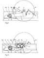
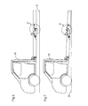
- crank axle is screwed to the vehicle frame, parts of the two longitudinal members 1 and a cross member 2 being recognizable from this vehicle frame.
- an axle guide tube 4 is attached to each side member, which is used for mounting a wheel suspension.
- each wheel suspension comprises a trailing arm 5, at one end of which an axle stub 6 is attached, which carries a wheel 8 via a hub provided with a braking device.
- the other end of the trailing arm 5 is provided with a bearing piece 9.
- an inner tube 11 is rotatably supported via bearing bushes 10, in which two bearing sleeves 12a and 12b are fastened.
- a support arm 13 is welded to the inner tube 11, which serves to support an air spring 14.
- this air spring 14 comprises an air bellows 14a which is fastened to the support arm 13 via a lower bracket 14b and to the cross member 2 of the vehicle frame via an upper bracket 14c.
- a spring support 14d is also arranged in the interior of the air bellows 14a, which serves on the one hand as an overload protection and on the other hand as an abutment of the upper bracket 14c in the lowered position according to FIG. 5.
- each trailing arm 5 is rigidly connected to the associated support arm 13 and the associated inner tube 11, which in turn is rotatably mounted in the respective axle guide tube 4.
- a fixation of the bearing piece 9 and the bearing sleeve 12a and thus the inner tube 11 in the axial longitudinal direction is carried out by grub screws 16 which engage through the bearing piece 9 or the bearing sleeve 12a in at least one of the connecting rods 15 and 15a and in this way prevent the Axle suspension can slip out of the side of the axle guide tube 4.
- the forces introduced into the wheels 8 are introduced off-center via the trailing arms 5 into the rotatable position elements of the wheel suspension.
- the axle guide tubes 4 and thus the longitudinal members 1 must therefore absorb bending stresses.
- the inner tubes 11 are extended toward the center of the vehicle beyond the bearing sleeves 12a.
- a rigid tube 17 is placed on each of these extended end pieces with the interposition of a bearing bush 10; in this way, bending stresses resulting from a greater load on a wheel suspension are transmitted via the connecting tube 17 to the bearing of the other wheel suspension, so that a certain compensation takes place with a simultaneous load reduction of the more heavily loaded bearing. So that there is no mutual influence of the independently acting wheel suspension, the connecting tube 17 is freely rotatable on the end pieces of the two inner tubes 11.
- FIG. 1 also shows that one of the four connecting rods, namely the connecting rod 15a is continuous. It also runs within the connecting tube 17 and acts in a manner known per se as a stabilizer.
- the connecting tube 17 described above has the effect that this connecting rod 15a, which acts as a stabilizer, is kept free from bending forces and is consequently loaded exclusively by torsional forces.
- Another advantage of the continuous connecting rod 15a can be seen in the fact that it connects the bearing elements of the two trailing arms 5, which are rotatable relative to the respective axle guide tube 4, so that it simultaneously serves to fix the track and absorbs forces occurring in the longitudinal direction of the axis.
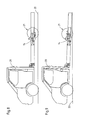
- a vibration damper 18 is arranged between each trailing arm 5 and the associated longitudinal member 1 of the vehicle frame, the vibration damper 18 being attached to the longitudinal member 1 by means of a bracket 18a.
- the drawings show a linkage 19 acting on the longitudinal member 5, which serves for the load-dependent brake control and level control, which can be switched off when the air springs 14 are relieved for the purpose of lowering the vehicle.
- the air-sprung crank axis is shown in a raised position, the driving position. It can be seen that the vehicle frame is aligned approximately parallel to the road. 4 and 5, on the other hand, show the same air-sprung crank axis in a lowered position, as is assumed, for example, when the vehicle is to be loaded or unloaded or when the vehicle is parked. In this case, the air spring 14 is vented, so that the spring support 14d rests against the upper bracket 14c of the air spring 14. In this lowered position, the spring support 14d prevents the bellows 14 from being damaged.
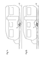
- 6 to 11 show a motor vehicle with a driver's cab 20 and an adjoining vehicle frame, on which various bodies, such as a platform or a box body, can be placed.
- the rear axle 21 is designed as an air-sprung crank axle.
- 6, 8 and 10 show the motor vehicle in the driving position, the air springs 14 being ventilated so that the vehicle frame is aligned approximately parallel to the roadway 22.
- This central axis is designed as an air-sprung crank axis.
- the air-sprung crank axle according to the invention can also be used as a double axle unit, as is shown, for example, in FIGS. 18 to 23 using the example of a double axle trailer.
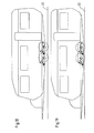
- 18, 20 and 22 also show the caravan with the air-sprung crank axle in the driving position and FIGS. 19, 21 and 23 in a lowered position, as is assumed, for example, when the caravan is parked on campsites.
- the air suspension cure according to the invention can also be used in vehicles that, due to their design, only offer a limited installation volume for the air suspension or for a lowering device. This is particularly the case in the light trucks shown in FIGS. 6 to 11 and in the caravans shown in FIGS. 12 to 23.
- the air suspension bellows can be subjected to a different pressure, so that one-sided loading of the axle is compensated for and the driving properties of the trailer are improved.
- the crank axle according to the invention it is possible with the crank axle according to the invention to lower the trailer to such an extent that the axle or axles are relieved in the parked state when the caravan is supported at the front and rear. It is advantageous here that the trailer can be lowered to such an extent that relatively short supports can be used. Furthermore; lowering the entire trailer frame makes it easier to get into the trailer.
- the air springs have external; ne valves can be ventilated or vented.
- the air springs can be vented or vented, for example, at petrol stations or in workshops.
- a label can be attached to the frame or on the bellows, which indicates to the driver the correct air pressure in the air springs.
Landscapes
- Engineering & Computer Science (AREA)
- Mechanical Engineering (AREA)
- Vehicle Body Suspensions (AREA)
Abstract
Description
Die Erfindung betrifft eine luftgefederte Kurbelachse für Kraftfahrzeuge und Anhänger mit in einem an Längsträgern des Fahrzeugrahmens angeordneten Achsführungsrohr verschwenkbar gelagerten Längslenkern, an denen ein die Radnabe und Bremse tragender Achsstummel angeordnet ist und die jeweils durch mindestens eine Luftfeder gegenüber dem Fahrzeugrahmen abgestützt sind.The invention relates to an air-sprung crank axle for motor vehicles and trailers with longitudinal links pivotably mounted in an axle guide tube arranged on the longitudinal members of the vehicle frame, on which an axle stub supporting the wheel hub and brake is arranged and which are each supported by at least one air spring relative to the vehicle frame.
Es sind derartige luftgefederte Kurbelachsen bekannt, die Zwei Längslenker aufweisen, welche an einem Achsführungsrohr verschwenkbar gelagert angeordnet sind. Bei diesen vorbekannten Achsen sind zwischen den Längslenkern und dem Fahrzeugrahmen Luftfederbälge angeordnet. Nachteil dieser Achsen ist, daß sie aufgrund der Inanspruchnahme eines großen Einbauvolumens nur bei entsprechend großen Fahrzeugen einsetzbar sind.Such air-sprung crank axles are known, which have two trailing arms, which are pivotally mounted on an axle guide tube. In these known axles, air suspension bellows are arranged between the trailing arms and the vehicle frame. The disadvantage of these axles is that, due to the fact that they require a large installation volume, they can only be used in vehicles of corresponding size.
Ausgehend von diesem Stand der Technik liegt der Erfindung die Aufgabe zugrunde, eine luftgefederte Kurbelachse zu schaffen, die ein geringes Einbauvolumen beansprucht und mit der ein tiefes Absenken des Fahrzeugrahmens möglich ist.Proceeding from this prior art, the object of the invention is to create an air-sprung crank axle which requires a small installation volume and with which a deep lowering of the vehicle frame is possible.
Diese Aufgabe wird erfindungsgemäß dadurch gelöst, daß die Längslenker unabhängig voneinander verschwenkbar im Achsführungsrohr gelagert und die Luftfederbälge der Luftfedern gemeinsam zum Absenken des Fahrzeugrahmens entlüftbar sind.This object is achieved in that the trailing arms are pivotally mounted independently of each other in the axle guide tube and the bellows of the air springs can be vented together to lower the vehicle frame.
Eine erfindungsgemäß gestaltete Kurbelachse weist die Vorteile einzeln aufgehängter Räder in Verbindung mit einer Luftfederung auf, wobei der Rahmen des Fahrzeuges durch Be- oder Entlüften der Lüftungsbälge angehoben bzw. abgesenkt werden kann. Das Absenken des Fahrzeugrahmens ist beispielsweise dann von Vorteil, wenn das Fahrzeug ohne Rampe bzw. Auffahrbrücke beladen werden soll.A crank axle designed according to the invention has the advantages of individually suspended wheels in connection with an air suspension, the frame of the vehicle being able to be raised or lowered by ventilating or venting the ventilation bellows. Lowering the vehicle frame is advantageous, for example, if the vehicle is to be loaded without a ramp or ramp.
Bei einer bevorzugten Ausführungsform der Erfindung sind die Luftfedern zwischen den Längsträgern des Fahrzeugrahmens angeordnet und mit ihrer unteren Konsole jeweils an einem Tragarm abgestützt, der über eine Lagerhülse verdrehbar im Achsführungsrohr gelagert und unverdrehbar mit dem zugehörigen Längslenker verbunden ist. Bei dieser Ausgestaltung ist es besonders vorteilhaft, daß kein Bauelement der Radaufhängung oberhalb der Oberkante des Fahrzeugrahmens angeordnet ist, so daß der Fahrzeugaufbau direkt auf dem Fahrzeugrahmen montiert werden kann, ohne daß zwischen dem Fahrzeugrahmen und dem Fahrzeugaufbau eine Distanz eingehalten werden muß. Ferner wird hierdurch die Bodenfreiheit des Fahrzeuges nicht eingeschränkt.In a preferred embodiment of the invention, the air springs are arranged between the longitudinal beams of the vehicle frame and are each supported with their lower bracket on a support arm which is rotatably mounted in the axle guide tube via a bearing sleeve and is non-rotatably connected to the associated trailing arm. In this embodiment, it is particularly advantageous that no component of the wheel suspension is arranged above the upper edge of the vehicle frame, so that the vehicle body can be mounted directly on the vehicle frame without having to maintain a distance between the vehicle frame and the vehicle body. Furthermore, this does not restrict the vehicle's ground clearance.
Die Lagerhülse des die Luftfeder abstützenden Tragarmes ist mit einem im Achsführungsrohr gelagerten Innenrohr verbunden, so daß sich eine einfache drehfeste Verbindung zwischen dem Tragarm und dem Längslenker ergibt. Zwischen dem Achsführungsrohr und dem Innenrohr sind vorzugsweise Lagerbuchsen angeordnet, die eine möglichst reibungsarme Verdrehung des Innenrohres in dem fest eingespannten Achsführungsrohr ermöglichen.The bearing sleeve of the support arm supporting the air spring is connected to an inner tube mounted in the axle guide tube, so that there is a simple non-rotatable connection between the support arm and the trailing arm. Bearing bushes are preferably arranged between the axle guide tube and the inner tube, which enable the inner tube to be rotated in the firmly clamped axle guide tube with as little friction as possible.
Bei einer Weiterbildung der erfindungsgemäßen Kurbelachse ist vorgesehen, daß die Innenrohre die jeweilige Lagerhülse zur Mitte des Fahrzeugrahmens überragen und daß auf diesen Endstükken der Innenrohre ein Verbindungsrohr frei drehbar gelagert ist. Dieses Verbindungsrohr nimmt in vorteilhafter Weise die Biegebeanspruchung der einzeln angelenkten Radaufhängungen auf, so daß auf weitere Konstruktionselemente zur Stützung der Achsführungsrohre der einzelnen Radaufhängung verzichtet werden kann. Das Verbindungsrohr dient der Fixierung von Tragarm und Längslenker in Achslängsrichtung und relativ zum Achsführungsrohr, d.h. zum Fahrzeugrahmen. Bei einer Weiterbildung ist mindestens ein Verbindungsstab zur Verbindung der beiden Radaufhängungen durchgehend als Stabilisator ausgebildet. Dieser Verbindungsstab dient zum einen der Spurweitenfixierung und zum anderen der Stabilisierung der Fahreigenschaften des Fahrzeuges. Durch diesen Stabilisator werden Bewegungen des Fahrzeuges um seine Längsachse reduziert, die beim Überfahren einseitiger Fahrbahnunebenheiten entstehen.In a further development of the crank axle according to the invention it is provided that the inner tubes protrude beyond the respective bearing sleeve to the center of the vehicle frame and that a connecting tube is freely rotatably mounted on these end pieces of the inner tubes. This connecting tube advantageously absorbs the bending stress of the individually articulated wheel suspensions, so that there is no need for further structural elements for supporting the axle guide tubes of the individual wheel suspensions. The connecting tube is used to fix the support arm and trailing arm in the longitudinal axis direction and relative to the axle guide tube, i.e. to the vehicle frame. In one development, at least one connecting rod for connecting the two wheel suspensions is designed continuously as a stabilizer. This connecting rod serves on the one hand to fix the track gauge and on the other hand to stabilize the driving characteristics of the vehicle. This stabilizer reduces movements of the vehicle around its longitudinal axis that occur when driving over uneven road surfaces.
Zur Fixierung der Tragarme für die Luftfedern und der Längslenker ist vorgesehen, daß die Lagerhülsen und Lagerstücke jeweils über eine Madenschraube in Achslängsrichtung mit dem durchgehenden Verbindungsstab verbunden sind. Mit diesen Madenschrauben wird eine Bewegung der Lagerhülsen und Lagerstücke in Achslängsrichtung während des Fahrbetriebes verhindert. Ferner können durch diese Ausgestaltung die Bauelemente zueinander justiert werden.To fix the support arms for the air springs and the trailing arms, it is provided that the bearing sleeves and bearing pieces are each connected to the continuous connecting rod in the axial longitudinal direction via a grub screw. With these grub screws, movement of the bearing sleeves and bearing pieces in the longitudinal axis direction is prevented during driving. Furthermore, the components can be adjusted to one another by this configuration.
Zur Dämpfung der beim Fahrbetrieb entstehenden Schwingungen des Fahrzeugaufbaus ist zwischen der Radaufhängung und dem Fahrzeugrahmen ein Schwingungsdämpfer angeordnet.A vibration damper is arranged between the wheel suspension and the vehicle frame to dampen the vibrations of the vehicle body that arise during driving operation.
Es ist ferner bei einer bevorzugten Ausführungsform vorgesehen, daß die Luftfedern mit einer zum Heben und Senken abschaltbaren Niveauregelung ausgerüstet und als Sensor zur lastabhängigen Bremsansteuerung ausgebildet sind.It is further provided in a preferred embodiment that the air springs are equipped with a level control which can be switched off for lifting and lowering and are designed as a sensor for load-dependent brake control.
Weitere Einzelheiten und Vorteile ergeben sich aus der nachfolgenden Beschreibung der zugehörigen Zeichnung, in welcher eine bevorzugte Ausführungsform einer erfindungsgemäß ausgebildeten luftgefederten Kurbelachse dargestellt ist. In der Zeichnung zeigen:
- Fig. 1 eine an die Unterseite der Längsträger eines Fahrzeugrahmens angeschraubte in einer waagerechten geschnittenen Ansicht;
- Fig. 2 eine luftgefederte Kurbelachse in angehobener Stellung in einer geschnittenen Ansicht entlang der Linie 11-11 in Fig. 1;
- Fig. 3 die luftgefederte Kurbelachse gemäß Fig. 2 in einer geschnittenen Ansicht entlang der Linie 111-111 in Fig. 1;
- Fig. 4 die luftgefederte Kurbelachse gemäß Fig. 2 in einer abgesenkten Position;
- Fig. 5 die luftgefederte Kurbelachse gemäß Fig. 3 in einer abgesenkten Position;
- Fig. 6 ein Kraftfahrzeug mit einer luftgefederten Kurbelachse in Fahrstellung in Seitenansicht;
- Fig. 7 das Kraftfahrzeug gemäß Fig. 6 mit abgesenktem Rahmen in Seitenansicht;
- Fig. 8 das Fahrzeug gemäß Fig. 6 in einer teilweise geschnitten dargestellten Seitenansicht;
- Fig. 9 das Kraftfahrzeug gemäß Fig. 7 in einer teilweise geschnitten dargestellten Seitenansicht;
- Fig. 10 das Kraftfahrzeug gemäß den
Figuren 6 und 8 in einer teilweise geschnitten dargestellten Seitenansicht entlang der Linie III-III in Fig. 1; - Fig. 11 das Kraftfahrzeug gemäß Fig. 7 und 9 in einer teilweise geschnitten dargestellten Seitenansicht entlang der Linie III-III der Fig. 1;
- Fig. 12 einen Anhänger mit einer als Zentralachse ausgebildeten Kurbelachse in Fahrstellung;
- Fig. 13 den Anhänger gemäß Fig. 12 in abgesenkter Stellung;
- Fig. 14 den Anhänger gemäß Fig. 12 in einer teilweise geschnittenen Seitenansicht;
- Fig. 15 den Anhänger gemäß Fig. 13 in einer teilweise geschnitten dargestellten Seitenansicht;
- Fig. 16 den Anhänger gemäß den Fig. 12 und 14 in einer teilweise geschnittenen Seitenansicht entlang der Linie III-III der Fig. 1;
- Fig. 17 den Anhänger gemäß den Fig. 13 und 15 in einer teilweise geschnitten dargestellten Seitenansicht entlang der Linie III-III der Fig. 1;
- Fig. 18 einen Anhänger mit einem zentral angeordneten Doppelachsaggregat in Fahrstellung in einer Seitenansicht;
- Fig. 19 den Anhänger gemäß Fig. 18 in abgesenkter Stellung;
- Fig. 20 den Anhänger gemäß Fig. 18 in einer teilweise geschnitten dargestellten Seitenansicht;
- Fig. 21 den Anhänger gemäß Fig. 19 in einer teilweise geschnitten dargestellten Seitenansicht;
- Fig. 22 den Anhänger gemäß den Fig. 18 und 20 in einer teilweise geschnitten dargestellten Seitenansicht entlang der Linie III-III der Fig. und
- Fig. 23 den Anhänger gemäß den Fig. 19 und 21 in einer teilweise geschnitten dargestellten Seitenansicht entlang der Linie III-III der Fig. 1.
- Figure 1 is a screwed to the underside of the side members of a vehicle frame in a horizontal sectional view.
- Fig. 2 shows an air-sprung crank axle in elevated position in a sectional view along the line 11-11 in Fig. 1;
- 3 shows the air-sprung crank axle according to FIG. 2 in a sectional view along the line 111-111 in FIG. 1;
- FIG. 4 shows the air-sprung crank axle according to FIG. 2 in a lowered position;
- 5 shows the air-sprung crank axle according to FIG. 3 in a lowered position;
- 6 shows a motor vehicle with an air-sprung crank axle in the driving position in a side view;
- 7 shows the motor vehicle according to FIG. 6 with the frame lowered in a side view;
- 8 shows the vehicle according to FIG. 6 in a partially sectioned side view;
- FIG. 9 shows the motor vehicle according to FIG. 7 in a partially sectioned side view;
- 10 shows the motor vehicle according to FIGS. 6 and 8 in a side view, partly in section, along the line III-III in FIG. 1;
- 11 shows the motor vehicle according to FIGS. 7 and 9 in a side view, partly in section, along the line III-III of FIG. 1;
- 12 shows a trailer with a crank axis designed as a central axis in the driving position;
- 13 shows the trailer according to FIG. 12 in the lowered position;
- FIG. 14 shows the trailer according to FIG. 12 in a partially sectioned side view;
- FIG. 15 shows the trailer according to FIG. 13 in a partially sectioned side view;
- 16 shows the trailer according to FIGS. 12 and 14 in a partially sectioned side view along the line III-III of FIG. 1;
- 17 shows the trailer according to FIGS. 13 and 15 in a side view, partly in section, along the line III-III of FIG. 1;
- 18 shows a side view of a trailer with a centrally arranged double-axle unit in the driving position;
- 19 the trailer according to FIG. 18 in the lowered position;
- 20 shows the trailer according to FIG. 18 in a partially sectioned side view;
- FIG. 21 shows the trailer according to FIG. 19 in a partially sectioned side view;
- Fig. 22 shows the trailer according to Figs. 18 and 20 in a partially sectioned side view along the line III-III of Fig. And
- 23 the trailer according to FIGS. 19 and 21 in a partially sectioned side view along the line III-III of FIG. 1.
Beim dargestellten Ausführungsbeispiel ist die Kurbelachse am Fahrzeugrahmen angeschraubt, wobei von diesem Fahrzeugrahmen Teile der beiden Längsträger 1 und ein Querträger 2 zu erkennen sind. Mittels einer Tragkonsole 3 ist an jedem Längsträger ein Achsführungsrohr 4 befestigt, das zur Lagerung jeweils einer Radaufhängung dient.In the illustrated embodiment, the crank axle is screwed to the vehicle frame, parts of the two
Wie insbesondere aus Fig. 1 hervorgeht, umfaßt jede Radaufhängung einen Längslenker 5, an dessen einem Ende ein Achsstummel 6 befestigt ist, der über eine mit einer Bremsvorrichtung versehenen Nabe ein Rad 8 trägt. Das andere Ende des Längslenkers 5 ist mit einem Lagerstück 9 versehen.As can be seen in particular from FIG. 1, each wheel suspension comprises a trailing
Im Achsführungsrohr 4 ist über Lagerbuchsen 10 ein Innenrohr 11 drehbar gelagert, in dem zwei Lagerhülsen 12a und 12b befestigt sind. Im Bereich der Lagerhülse 12a ist an das Innenrohr 11 ein Tragarm 13 angeschweißt, der zur Abstützung einer Luftfeder 14 dient.In the
Wie am besten in Fig. 3 zu erkennen ist, umfaßt diese Luftfeder 14 einen Luftfederbalg 14a, der über eine untere Konsole 14b am Tragarm 13 und über eine obere Konsole 14c am Querträger 2 des Fahrzeugrahmens befestigt ist. Im Inneren des Luftfederbalges 14a ist außerdem eine Federstütze 14d angeordnet, die einerseits als Überlastsicherung und andererseits als Anlage der oberen Konsole 14c in der abgesenkten Stellung gemäß Fig. 5 dient.As can best be seen in FIG. 3, this
Die verschwenkbare Lagerung des Längslenkers 5 erfolgt beim Ausführungsbeispiel durch vier Verbindungsstäbe 15, 15a, die formschlüssig einerseits in das am Längslenker 5 befestigte Lagerstück 9 und andererseits in die Lagerhülsen 12a und 12b eingreifen. Auf diese Weise ist jeder Längslenker 5 starr mit dem zugehörigen Tragarm 13 und dem zugehörigen Innenrohr 11 verbunden, das seinerseits verdrehbar im jeweiligen Achsführungsrohr 4 gelagert ist. Eine Fixierung des Lagerstückes 9 und der Lagerhülse 12a und damit des Innenrohres 11 in Achslängsrichtung erfolgt durch Madenschrauben 16, die durch das Lagerstück 9 bzw. die Lagerhülse 12a hindurch in mindestens einen der Verbindungsstäbe 15 bzw. 15a eingreifen und auf diese Weise verhindern, daß die Achsaufhängung seitlich aus dem Achsführungsrohr 4 heraus rutschen kann.The pivotable mounting of the trailing
Wie besonders deutlich aus Fig. 1 hervorgeht, werden die in die Räder 8 eingeleiteten Kräfte über die Längslenker 5 außermittig in die verdrehbaren Lageelemente der Radaufhängung eingeleitet. Die Achsführungsrohre 4 und damit die Längsträger 1 müssen demzufolge Biegebeanspruchungen aufnehmen. Um diese Biegebeanspruchungen auf niedrige Werte zu reduzieren, sind die Innenrohre 11 in Richtung zur Fahrzeugmitte über die Lagerhülsen 12a hinaus verlängert. Auf diese verlängerten Endstücke ist unter Zwischenschaltung jeweils einer Lagerbuchse 10 ein biegesteifes Rohr 17 aufgesetzt; hierdurch werden aus einer stärkeren Belastung einer Radaufhängung herrührende Biegebeanspruchungen über das Verbindungsrohr 17 auf die Lagerstelle der jeweils anderen Radaufhängung übertragen, so daß ein gewisser Ausgleich bei gleichzeitiger Lastreduzierung der stärker belasteten Lagerstelle stattfindet. Damit keine gegenseitige Beeinflußung der unabhängig voneinander wirkenden Radaufhängung auftritt, ist das Verbindungsrohr 17 frei drehbar auf den Endstücken der beiden Innenrohre 11 gelagert.As can be seen particularly clearly from FIG. 1, the forces introduced into the
Das Ausführungsbeispiel in Fig. 1 zeigt weiterhin, daß einer der vier Verbindungsstäbe, nämlich der Verbindungsstab 15a durchgehend ausgeführt ist. Er verläuft auch innerhalb des Verbindungsrohres 17 und wirkt in ansich bekannter Weise als Stabilisator. Das voranstehend beschriebene Verbindungsrohr 17 bewirkt hierbei, daß dieser als Stabilisator wirkende Verbindungsstab 15a von Biegekräften freigehalten und demzufolge ausschließlich durch Torsionskräfte belastet wird. Ein weiterer Vorteil des durchgehenden Verbindungsstabes 15a ist darin zu sehen, daß er die gegenüber dem jeweiligen Achsführungsrohr 4 verdrehbaren Lagerelemente der beiden Längslenker 5 miteinander verbindet, so daß er gleichzeitig der spurweiten Fixierung dient und in Längsrichtung der Achse auftretende Kräfte aufnimmt.The embodiment in Fig. 1 also shows that one of the four connecting rods, namely the connecting
Beim Ausführungsbeispiel ist zwischen jedem Längslenker 5 und dem zugehörigen Längsträger 1 des Fahrzeugrahmens ein Schwingungsdämpfer 18 angeordnet, dessen Befestigung am Längsträger 1 mittels einer Konsole 18a erfolgt. Außerdem zeigen die Zeichnungen ein am Längsträger 5 angreifendes Gestänge 19, daß der lastabhängigen Bremsansteuerung und einer Niveauregulierung dient, die abgeschaltet werden kann, wenn zwecks Absenkung des Fahrzeuges die Luftfedern 14 entlastet werden.In the exemplary embodiment, a
In den Fig. 2 und 3 ist die luftgefederte Kurbelachse in einer angehobenen Stellung, der Fahrstellung dargestellt. Es ist zu erkennen, daß der Fahrzeugrahmen annähernd parallel zur Fahrbahn ausgerichtet ist. Die Fig. 4 und 5 dagegen zeigen die gleiche luftgefederte Kurbelachse in einer abgesenkten Position, wie sie beispielsweise eingenommen wird, wenn das Fahrzeug be- oder entladen werden soll bzw. wenn das Fahrzeug abgestellt ist. In diesem Fall ist die Luftfeder 14 entlüftet, so daß die Federstütze 14d an der oberen Konsole 14c der Luftfeder 14 anliegt. Die Federstütze 14d verhindert in dieser abgesenkten Stellung, daß der Federbalg 14 beschädigt wird.2 and 3, the air-sprung crank axis is shown in a raised position, the driving position. It can be seen that the vehicle frame is aligned approximately parallel to the road. 4 and 5, on the other hand, show the same air-sprung crank axis in a lowered position, as is assumed, for example, when the vehicle is to be loaded or unloaded or when the vehicle is parked. In this case, the
In den Fig. 6 bis 11 ist ein Kraftfahrzeug mit einem Führerhaus 20 und einem sich daran anschließenden Fahrzeugrahmen dargestellt, auf den verschiedene Aufbauten, wie beispielsweise eine Pritsche oder ein Kastenaufbau aufgesetzt werden können. Die Hinterachse 21 ist als luftgefederte Kurbelachse ausgeführt. Die Fig. 6, 8 und 10 zeigen das Kraftfahrzeug in der Fahrstellung, wobei die Luftfedern 14 belüftet sind, so daß der Fahrzeugrahmen annähernd parallel zur Fahrbahn 22 ausgerichtet ist.6 to 11 show a motor vehicle with a driver's
Die Fig. 7, 9 und 11 zeigen das gleiche Fahrzeug, bei dem der hintere Teil des Fahrzeugrahmens durch entlüften der Luftfedern abgesenkt ist. In dieser Stellung des Fahrzeuges, in der das hintere Ende des Fahrzeugrahmens fast bis auf die Fahrbahn 22 abgesenkt ist, kann der in der Figuren nicht dargestellte Fahrzeugaufbau ohne eine Rampe bzw. Überfahrbrücke beladen werden. Insbesondere bei Fahrzeugen zum Transport von Krankenfahrstühlen oder dgl. können diese Krankenfahrstühle leicht in einen Kastenaufbau eingeschoben werden. Es ist aber auch möglich, bei einem derartigen Fahrzeug eine Aufbauwechselvorrichtung vorzusehen, so daß diese ohne Hilfe eines Kranes oder dgl. abgesetzt werden kann.7, 9 and 11 show the same vehicle in which the rear part of the vehicle frame is lowered by venting the air springs. In this position of the vehicle, in which the rear end of the vehicle frame is almost lowered to the
In den Fig. 12 bis 17 ist ein eine Zentralachse aufweisender Anhänger dargestellt. Diese Zentralachse ist als luftgefederte Kurbelachse ausgebildet.12 to 17, a trailer having a central axis is shown. This central axis is designed as an air-sprung crank axis.
Die Fig. 12, 14 und 16 zeigen den Anhänger, der hier als Wohnanhänger dargestellt ist, in seiner Fahrstellung, wobei die Luftfedern 14 belüftet sind und der Anhängerrahmen einen ausreichenden Abstand von der Fahrbahn 22 hat, so daß er auch bei Unebenheiten nicht mit der Fahrbahn 22 in Kontakt kommen kann. Die Fig. 13, 15 und 17 zeigen den gleichen Wohnanhänger mit entlüfteten Luftfedern 14. In dieser Stellung ist der Anhängerrahmen fast bis auf die Fahrbahn 22 abgesenkt.12, 14 and 16 show the trailer, which is shown here as a caravan, in its driving position, the air springs 14 are ventilated and the trailer frame is at a sufficient distance from the
Die erfindungsgemäße luftgefederte Kurbelachse ist auch als Doppelachsaggregat einsetzbar, wie es beispielsweise in den Fig. 18 bis 23 am Beispiel eines doppelachsigen Wohnanhängers dargestellt ist. Auch hier zeigen die Fig. 18, 20 und 22 den Wohnanhänger mit der luftgefederten Kurbelachse in Fahrstellung und die Fig. 19, 21 und 23 in einer abgesenkten Stellung, wie sie beispielsweise beim Abstellen des Wohnanhängers auf Campingplätzen eingenommen wird.The air-sprung crank axle according to the invention can also be used as a double axle unit, as is shown, for example, in FIGS. 18 to 23 using the example of a double axle trailer. 18, 20 and 22 also show the caravan with the air-sprung crank axle in the driving position and FIGS. 19, 21 and 23 in a lowered position, as is assumed, for example, when the caravan is parked on campsites.
Insbesondere aus den Fig. 6 bis 23 wird deutlich, daß die erfindungsgemäße luftgefederte Kurbelachse auch bei Fahrzeugen eingesetzt werden kann, die konstruktionsbedingt nur ein begrenztes Einbauvolumen für die Luftfederung bzw. für eine Absenkvorrichtung bieten. Dies ist vor allem bei den in den Fig. 6 bis 11 dargestellten Kleinlastkraftwagen und bei den in den Fig. 12 bis 23 dargestellten Wohnanhängern der Fall.In particular from FIGS. 6 to 23 it is clear that the air suspension cure according to the invention can also be used in vehicles that, due to their design, only offer a limited installation volume for the air suspension or for a lowering device. This is particularly the case in the light trucks shown in FIGS. 6 to 11 and in the caravans shown in FIGS. 12 to 23.
Beispielsweise können bei den Wohnanhängern die Luftfederbälge mit einem unterschiedlichen Druck beaufschlagt werden, so daß eine einseitige Beladung der Achse ausgeglichen wird und die Fahreigenschaften des Anhängers verbessert werden. Andererseits ist es mit der erfindungsgemäßen Kurbelachse möglich, den Anhänger soweit abzusenken, daß die Achse bzw. die Achsen im abgestellten Zustand entlastet werden, wenn der Wohnanhänger vorne und hinten abgestützt wird. Hierbei ist es vorteilhaft, daß der Anhänger soweit abgesenkt werden kann, daß relativ kurze Abstützungen verwendet werden können. Ferner wird ; durch das Absenken des gesamten Anhängerrahmens der Einstieg in den Anhänger erleichert.For example, in the case of caravans, the air suspension bellows can be subjected to a different pressure, so that one-sided loading of the axle is compensated for and the driving properties of the trailer are improved. On the other hand, it is possible with the crank axle according to the invention to lower the trailer to such an extent that the axle or axles are relieved in the parked state when the caravan is supported at the front and rear. It is advantageous here that the trailer can be lowered to such an extent that relatively short supports can be used. Furthermore; lowering the entire trailer frame makes it easier to get into the trailer.
Da Anhänger und zum Teil auch Kleinlastkraftwagen nicht über einen eigenen Kompressor verfügen ist vorgesehen, daß die Luftfedern über exter- ; ne Ventile belüftet bzw. entlüftet werden können. Das Belüften bzw. Entlüften der Luftfedern kann beispielsweise an Tankstellen oder in Werkstätten erfolgen. Um dem Fahrer anzuzeigen, wann der richtige Luftdruck in den Luftfedern erreicht ist, kann am Rahmen oder am Federbalg eine Kennzeichnung angebracht sein, die dem Fahrer den richtigen Luftdruck in den Luftfedern anzeigt.Since trailers and some small trucks do not have their own compressor, it is provided that the air springs have external; ne valves can be ventilated or vented. The air springs can be vented or vented, for example, at petrol stations or in workshops. In order to indicate to the driver when the correct air pressure in the air springs has been reached, a label can be attached to the frame or on the bellows, which indicates to the driver the correct air pressure in the air springs.
- 1 Längsträger1 side member
- 2 Querträger2 cross beams
- 3 Tragkonsole3 support bracket
- 4 Achsführungsrohr4 axis guide tube
- 5 Längslenker5 trailing arms
- 6 Achsstummel6 stub axles
- 7 Nabe7 hub
- 8 Rad8 wheel
- 9 Lagerstück9 stock
- 10 Lagerbuchse10 bearing bush
- 11 Innenrohr11 inner tube
- 12a Lagerhülse12a bearing sleeve
- 12b Lagerhülse12b bearing sleeve
- 13 Tragarm :13 support arm:
- 14 Luftfeder14 air spring
- 14a Luftfederbalg14a air bellows
- 14b untere Konsole14b lower console
- 14c obere Konsole14c upper console
- 14d Federstütze ;14d spring support;
- 15 Verbindungsstab15 connecting rod
- 15a Verbindungsstab15a connecting rod
- 16 Madenschrauben16 grub screws
- 17 Verbindungsrohr17 connecting pipe
- 18 Schwingungsdämpfer18 vibration dampers
- 18a Konsole18a console
- 19 Gestänge19 rods
- 20 Führerhaus20 cab
- 21 Hinterachse21 rear axle
- 22 Fahrbahn22 lane
Claims (8)
dadurch gekennzeichnet,
daß die Längslenker (1) unabhängig voneinander verschwenkbar im Achsführungsrohr (4) gelagert und die Luftfederbälge (14a) der Luftfedern (14) gemeinsam zum Absenken des Fahrzeugrahmens entlüftbar sind,
daß die Luftfedern (14) zwischen den Längsträgern (1) des Fahrzeugrahmens angeordnet und mit ihrer unteren Konsole (14b) jeweils an einem Tragarm (13) abgestützt sind, der über eine Lagerhülse (12a,12b) verdrehbar im Achsführungstohr (4) gelagert und unverdrehbar mit dem zugehörigen Längslenker (1) verbunden ist, und
daß die Innenrogre (11) die jeweilige Lagerhülse (12a,12b) zur Mitte des Fahrzeugrahmens überragen und daß auf diesen Endstücken der Innenrohre (11) ein Verbindungsrohr (17) frei drehbar gelagert ist.1. Air-sprung crank axle for motor vehicles and trailers with longitudinal links pivotably mounted in an axle guide tube arranged on the longitudinal members of the vehicle frame, on which an axle stub supporting the wheel hub and brake is arranged and which are each supported by at least one air spring relative to the vehicle frame,
characterized,
that the trailing arms (1) can be pivoted independently of one another in the axle guide tube (4) and the air bellows (14a) of the air springs (14) can be vented together to lower the vehicle frame,
that the air springs (14) are arranged between the side members (1) of the vehicle frame and are supported with their lower bracket (14b) on a respective support arm (13) which is rotatably supported in the axle guide tube (4) via a bearing sleeve (12a, 12b) and is non-rotatably connected to the associated trailing arm (1), and
that the inner tubes (11) protrude the respective bearing sleeve (12a, 12b) to the center of the vehicle frame and that a connecting tube (17) is freely rotatably mounted on these end pieces of the inner tubes (11).
Applications Claiming Priority (2)
| Application Number | Priority Date | Filing Date | Title |
|---|---|---|---|
| DE4021059 | 1990-07-04 | ||
| DE4021059A DE4021059A1 (en) | 1990-07-04 | 1990-07-04 | AIR SUSPENSED CRANKSHAFT |
Publications (2)
| Publication Number | Publication Date |
|---|---|
| EP0464412A1 true EP0464412A1 (en) | 1992-01-08 |
| EP0464412B1 EP0464412B1 (en) | 1993-03-03 |
Family
ID=6409517
Family Applications (1)
| Application Number | Title | Priority Date | Filing Date |
|---|---|---|---|
| EP91109585A Expired - Lifetime EP0464412B1 (en) | 1990-07-04 | 1991-06-11 | Pneumatical suspension with longitudinal arms |
Country Status (5)
| Country | Link |
|---|---|
| EP (1) | EP0464412B1 (en) |
| DE (2) | DE4021059A1 (en) |
| ES (1) | ES2038526T3 (en) |
| HU (1) | HU212173B (en) |
| YU (1) | YU112591A (en) |
Cited By (13)
| Publication number | Priority date | Publication date | Assignee | Title |
|---|---|---|---|---|
| DE19733968A1 (en) * | 1997-08-06 | 1999-02-25 | Bpw Bergische Achsen Kg | Crank axle for motor vehicles and trailers |
| EP1089888A4 (en) * | 1998-05-27 | 2003-03-05 | Aloha Llc | Axleless vehicle suspension system |
| WO2003106247A1 (en) * | 2002-06-18 | 2003-12-24 | Arboc Ltd. | Low load floor motor vehicle |
| US6986519B2 (en) | 1997-01-31 | 2006-01-17 | Aloha, Llc | Low profile chassis and suspension |
| US7425005B2 (en) | 2003-10-24 | 2008-09-16 | Aloha, Llc | Suspensions for low floor vehicles |
| US7559400B2 (en) | 1997-01-31 | 2009-07-14 | Aloha, Llc | Low profile chassis and suspension |
| US7568546B2 (en) | 2000-11-09 | 2009-08-04 | Diamond Force Engineering Llc | Low load floor motor vehicle |
| US7802801B2 (en) | 2007-10-02 | 2010-09-28 | Arboc Technologies Llc | Mass transit vehicle |
| EP2409861A1 (en) * | 2010-07-23 | 2012-01-25 | AL-KO Kober AG | Level regulator unit |
| US8371589B2 (en) | 2007-10-02 | 2013-02-12 | Arboc Technologies Llc | Mass transit vehicle |
| DE102004039973B4 (en) * | 2003-08-25 | 2017-02-02 | Iav Gmbh Ingenieurgesellschaft Auto Und Verkehr | Active suspension for vehicles |
| ITUA20163082A1 (en) * | 2016-05-02 | 2017-11-02 | Streparava S P A Con Socio Unico | A PNEUMATIC GROUP FOR A LIGHT COMMERCIAL VEHICLE; THE LIGHT TRADE VEHICLE; AND A METHOD OF ASSEMBLY OF THE LIGHT TRADE VEHICLE |
| EP3372427A1 (en) * | 2017-03-07 | 2018-09-12 | Volvo Construction Equipment AB | A working machine |
Families Citing this family (5)
| Publication number | Priority date | Publication date | Assignee | Title |
|---|---|---|---|---|
| US5887880A (en) * | 1996-05-22 | 1999-03-30 | Anadarko Bank & Trust Company | Squatdown axle and suspension system |
| US6142496A (en) * | 1999-03-12 | 2000-11-07 | Arboc Ltd. | Low load floor trailer and suspension system |
| US6237926B1 (en) | 1999-05-11 | 2001-05-29 | Boydstun Metal Works, Inc. | Independent suspension for a vehicle |
| DE102010060273A1 (en) | 2010-10-29 | 2012-05-03 | Manfred Mayer | Towed vehicle component e.g. trailer, for articulated train, has axle units arranged parallel to each other in rear portion of vehicle component and designed for supporting maximum weights respectively |
| DE102010060274A1 (en) | 2010-10-29 | 2012-05-03 | Manfred Mayer | Axle unit, particularly mono-wheel axis device, for loading vehicle such as motor vehicle, trailer or semi-trailer, has support structure as bearing load frame or center pivot plate |
Citations (6)
| Publication number | Priority date | Publication date | Assignee | Title |
|---|---|---|---|---|
| GB426703A (en) * | 1934-01-03 | 1935-04-08 | Porsche Gmbh | Improvements in and relating to springing arrangements for vehicles |
| US2597122A (en) * | 1946-08-07 | 1952-05-20 | Mechanical Handling Sys Inc | Air spring dual wheel running gear |
| FR2079967A5 (en) * | 1970-02-18 | 1971-11-12 | Citroen Sa | |
| US3822908A (en) | 1971-01-28 | 1974-07-09 | Mercadante J | Air suspension with tapered air bag |
| US4248455A (en) * | 1979-09-20 | 1981-02-03 | Manning Donald L | Heavy-duty suspension system |
| US4763953A (en) * | 1987-01-09 | 1988-08-16 | Chalin Thomas N | Trailer dump stop and stabilizer |
Family Cites Families (3)
| Publication number | Priority date | Publication date | Assignee | Title |
|---|---|---|---|---|
| DE732206C (en) * | 1941-02-17 | 1943-02-24 | Getefo Ges Fuer Tech Fortschri | Suspension for vehicles |
| US3713665A (en) * | 1971-01-28 | 1973-01-30 | Mercadante J | Air suspension with tapered air bag |
| DE3637387A1 (en) * | 1986-11-03 | 1988-05-05 | Sieben Hans Hermann | Wheel suspension for lowerable vehicle bodies |
-
1990
- 1990-07-04 DE DE4021059A patent/DE4021059A1/en not_active Withdrawn
-
1991
- 1991-06-11 ES ES199191109585T patent/ES2038526T3/en not_active Expired - Lifetime
- 1991-06-11 EP EP91109585A patent/EP0464412B1/en not_active Expired - Lifetime
- 1991-06-11 DE DE9191109585T patent/DE59100050D1/en not_active Expired - Fee Related
- 1991-06-26 YU YU112591A patent/YU112591A/en unknown
- 1991-07-03 HU HU912254A patent/HU212173B/en not_active IP Right Cessation
Patent Citations (6)
| Publication number | Priority date | Publication date | Assignee | Title |
|---|---|---|---|---|
| GB426703A (en) * | 1934-01-03 | 1935-04-08 | Porsche Gmbh | Improvements in and relating to springing arrangements for vehicles |
| US2597122A (en) * | 1946-08-07 | 1952-05-20 | Mechanical Handling Sys Inc | Air spring dual wheel running gear |
| FR2079967A5 (en) * | 1970-02-18 | 1971-11-12 | Citroen Sa | |
| US3822908A (en) | 1971-01-28 | 1974-07-09 | Mercadante J | Air suspension with tapered air bag |
| US4248455A (en) * | 1979-09-20 | 1981-02-03 | Manning Donald L | Heavy-duty suspension system |
| US4763953A (en) * | 1987-01-09 | 1988-08-16 | Chalin Thomas N | Trailer dump stop and stabilizer |
Cited By (18)
| Publication number | Priority date | Publication date | Assignee | Title |
|---|---|---|---|---|
| US6986519B2 (en) | 1997-01-31 | 2006-01-17 | Aloha, Llc | Low profile chassis and suspension |
| US7108271B2 (en) | 1997-01-31 | 2006-09-19 | Earl Dallas Smith | Axleless vehicle suspension system |
| US7559400B2 (en) | 1997-01-31 | 2009-07-14 | Aloha, Llc | Low profile chassis and suspension |
| DE19733968A1 (en) * | 1997-08-06 | 1999-02-25 | Bpw Bergische Achsen Kg | Crank axle for motor vehicles and trailers |
| EP1089888A4 (en) * | 1998-05-27 | 2003-03-05 | Aloha Llc | Axleless vehicle suspension system |
| US7568546B2 (en) | 2000-11-09 | 2009-08-04 | Diamond Force Engineering Llc | Low load floor motor vehicle |
| WO2003106247A1 (en) * | 2002-06-18 | 2003-12-24 | Arboc Ltd. | Low load floor motor vehicle |
| DE102004039973B4 (en) * | 2003-08-25 | 2017-02-02 | Iav Gmbh Ingenieurgesellschaft Auto Und Verkehr | Active suspension for vehicles |
| US7703781B2 (en) | 2003-10-24 | 2010-04-27 | Aloha, Llc | Suspensions for low floor vehicle |
| US7425005B2 (en) | 2003-10-24 | 2008-09-16 | Aloha, Llc | Suspensions for low floor vehicles |
| US7802801B2 (en) | 2007-10-02 | 2010-09-28 | Arboc Technologies Llc | Mass transit vehicle |
| US8371589B2 (en) | 2007-10-02 | 2013-02-12 | Arboc Technologies Llc | Mass transit vehicle |
| US8807575B2 (en) | 2007-10-02 | 2014-08-19 | Arboc Specialty Vehicles, Llc | Mass transit vehicle |
| EP2409861A1 (en) * | 2010-07-23 | 2012-01-25 | AL-KO Kober AG | Level regulator unit |
| ITUA20163082A1 (en) * | 2016-05-02 | 2017-11-02 | Streparava S P A Con Socio Unico | A PNEUMATIC GROUP FOR A LIGHT COMMERCIAL VEHICLE; THE LIGHT TRADE VEHICLE; AND A METHOD OF ASSEMBLY OF THE LIGHT TRADE VEHICLE |
| EP3241694A1 (en) * | 2016-05-02 | 2017-11-08 | Streparava S.p.A. Con Socio Unico | A pneumatic assembly for a light commercial vehicle; the light commercial vehicle; and an assembly method of the light commercial vehicle |
| EP3372427A1 (en) * | 2017-03-07 | 2018-09-12 | Volvo Construction Equipment AB | A working machine |
| WO2018162548A1 (en) * | 2017-03-07 | 2018-09-13 | Volvo Construction Equipment Ab | A working machine |
Also Published As
| Publication number | Publication date |
|---|---|
| DE59100050D1 (en) | 1993-04-08 |
| ES2038526T3 (en) | 1993-07-16 |
| HU212173B (en) | 1996-03-28 |
| HUT61692A (en) | 1993-03-01 |
| YU112591A (en) | 1994-11-15 |
| DE4021059A1 (en) | 1992-01-16 |
| EP0464412B1 (en) | 1993-03-03 |
| HU912254D0 (en) | 1991-12-30 |
Similar Documents
| Publication | Publication Date | Title |
|---|---|---|
| EP0464412B1 (en) | Pneumatical suspension with longitudinal arms | |
| DE60025912T2 (en) | SUSPENSION SYSTEM FOR ONE VEHICLE WHEEL | |
| DE69431764T2 (en) | Lift-axis suspension system in the form of a parallelogram with control of the axle pivot adjustment | |
| DE102010000886A1 (en) | Device for tiltably supporting a vehicle cabin of a vehicle | |
| EP2246207B1 (en) | Airport tow vehicle with pneumatic suspension | |
| EP0237619B1 (en) | Wheel suspension for vehicle superstructures which can be lowered, especially for trailers, front drive trucks (dormobiles), caravans | |
| DE19619189A1 (en) | Independent wheel suspension for an air-sprung, steerable wheel of a bus or truck | |
| EP1213162A1 (en) | Independent wheel suspension for sprung, steerable wheel | |
| EP0332037B1 (en) | Axle lifting device | |
| WO1998038074A1 (en) | Lifting system for an air-suspended vehicle axle | |
| WO2024074520A1 (en) | Wheel suspension system for a vehicle wheel of a motor vehicle, and motor vehicle | |
| EP0464415B1 (en) | Suspension with longitudinal arms for motorvehicles and trailers | |
| EP0895881B1 (en) | Suspension with longitudinal arms for motorvehicles and trailers | |
| DE102004058748B4 (en) | Multi-link rear suspension | |
| DE102017214640A1 (en) | Vehicle axle with a centrally arranged drive unit | |
| DE69304236T2 (en) | Wheel suspension device for a steerable front wheel set of a commercial vehicle | |
| DE102016222965A1 (en) | Arm | |
| EP0642938B1 (en) | Vehicle wheel suspension | |
| DE2907977C3 (en) | Trailers, in particular for agricultural machinery | |
| DE202014002176U1 (en) | Trailer axle with aligned in the direction of travel rubber spring elements | |
| DE102020204959B4 (en) | motor vehicle | |
| DE1780503C3 (en) | Suspension for semi-trailers | |
| EP0225851B1 (en) | Wheel suspension device for a cross-country vehicle moving slowly, particularly for a horse-drawn cart | |
| WO2005051687A1 (en) | Independent suspension for a motor vehicle wheel, particularly a non directed motor vehicle wheel | |
| EP0481197B1 (en) | Axle with pneumatic springs |
Legal Events
| Date | Code | Title | Description |
|---|---|---|---|
| PUAI | Public reference made under article 153(3) epc to a published international application that has entered the european phase |
Free format text: ORIGINAL CODE: 0009012 |
|
| AK | Designated contracting states |
Kind code of ref document: A1 Designated state(s): DE ES GB IT |
|
| 17P | Request for examination filed |
Effective date: 19911121 |
|
| 17Q | First examination report despatched |
Effective date: 19920601 |
|
| GRAA | (expected) grant |
Free format text: ORIGINAL CODE: 0009210 |
|
| AK | Designated contracting states |
Kind code of ref document: B1 Designated state(s): DE ES GB IT |
|
| ITF | It: translation for a ep patent filed | ||
| GBT | Gb: translation of ep patent filed (gb section 77(6)(a)/1977) |
Effective date: 19930309 |
|
| REF | Corresponds to: |
Ref document number: 59100050 Country of ref document: DE Date of ref document: 19930408 |
|
| REG | Reference to a national code |
Ref country code: ES Ref legal event code: FG2A Ref document number: 2038526 Country of ref document: ES Kind code of ref document: T3 |
|
| PLBE | No opposition filed within time limit |
Free format text: ORIGINAL CODE: 0009261 |
|
| STAA | Information on the status of an ep patent application or granted ep patent |
Free format text: STATUS: NO OPPOSITION FILED WITHIN TIME LIMIT |
|
| 26N | No opposition filed | ||
| PGFP | Annual fee paid to national office [announced via postgrant information from national office to epo] |
Ref country code: GB Payment date: 19970423 Year of fee payment: 7 |
|
| PGFP | Annual fee paid to national office [announced via postgrant information from national office to epo] |
Ref country code: ES Payment date: 19970630 Year of fee payment: 7 |
|
| PG25 | Lapsed in a contracting state [announced via postgrant information from national office to epo] |
Ref country code: GB Free format text: LAPSE BECAUSE OF NON-PAYMENT OF DUE FEES Effective date: 19980611 |
|
| PG25 | Lapsed in a contracting state [announced via postgrant information from national office to epo] |
Ref country code: ES Free format text: LAPSE BECAUSE OF EXPIRATION OF PROTECTION Effective date: 19980612 |
|
| PGFP | Annual fee paid to national office [announced via postgrant information from national office to epo] |
Ref country code: DE Payment date: 19980817 Year of fee payment: 8 |
|
| GBPC | Gb: european patent ceased through non-payment of renewal fee |
Effective date: 19980611 |
|
| PG25 | Lapsed in a contracting state [announced via postgrant information from national office to epo] |
Ref country code: DE Free format text: LAPSE BECAUSE OF NON-PAYMENT OF DUE FEES Effective date: 20000503 |
|
| REG | Reference to a national code |
Ref country code: ES Ref legal event code: FD2A Effective date: 20000601 |
|
| PG25 | Lapsed in a contracting state [announced via postgrant information from national office to epo] |
Ref country code: IT Free format text: LAPSE BECAUSE OF NON-PAYMENT OF DUE FEES;WARNING: LAPSES OF ITALIAN PATENTS WITH EFFECTIVE DATE BEFORE 2007 MAY HAVE OCCURRED AT ANY TIME BEFORE 2007. THE CORRECT EFFECTIVE DATE MAY BE DIFFERENT FROM THE ONE RECORDED. Effective date: 20050611 |