EP0464355A2 - Duplex centrifugal pump - Google Patents
Duplex centrifugal pump Download PDFInfo
- Publication number
- EP0464355A2 EP0464355A2 EP91108395A EP91108395A EP0464355A2 EP 0464355 A2 EP0464355 A2 EP 0464355A2 EP 91108395 A EP91108395 A EP 91108395A EP 91108395 A EP91108395 A EP 91108395A EP 0464355 A2 EP0464355 A2 EP 0464355A2
- Authority
- EP
- European Patent Office
- Prior art keywords
- insert
- side wall
- centrifugal pump
- flat side
- outlet
- Prior art date
- Legal status (The legal status is an assumption and is not a legal conclusion. Google has not performed a legal analysis and makes no representation as to the accuracy of the status listed.)
- Granted
Links
Images

Classifications
-
- F—MECHANICAL ENGINEERING; LIGHTING; HEATING; WEAPONS; BLASTING
- F04—POSITIVE - DISPLACEMENT MACHINES FOR LIQUIDS; PUMPS FOR LIQUIDS OR ELASTIC FLUIDS
- F04D—NON-POSITIVE-DISPLACEMENT PUMPS
- F04D1/00—Radial-flow pumps, e.g. centrifugal pumps; Helico-centrifugal pumps
-
- F—MECHANICAL ENGINEERING; LIGHTING; HEATING; WEAPONS; BLASTING
- F04—POSITIVE - DISPLACEMENT MACHINES FOR LIQUIDS; PUMPS FOR LIQUIDS OR ELASTIC FLUIDS
- F04D—NON-POSITIVE-DISPLACEMENT PUMPS
- F04D13/00—Pumping installations or systems
- F04D13/12—Combinations of two or more pumps
- F04D13/14—Combinations of two or more pumps the pumps being all of centrifugal type
-
- F—MECHANICAL ENGINEERING; LIGHTING; HEATING; WEAPONS; BLASTING
- F04—POSITIVE - DISPLACEMENT MACHINES FOR LIQUIDS; PUMPS FOR LIQUIDS OR ELASTIC FLUIDS
- F04D—NON-POSITIVE-DISPLACEMENT PUMPS
- F04D15/00—Control, e.g. regulation, of pumps, pumping installations or systems
- F04D15/0072—Installation or systems with two or more pumps, wherein the flow path through the stages can be changed, e.g. series-parallel
-
- F—MECHANICAL ENGINEERING; LIGHTING; HEATING; WEAPONS; BLASTING
- F04—POSITIVE - DISPLACEMENT MACHINES FOR LIQUIDS; PUMPS FOR LIQUIDS OR ELASTIC FLUIDS
- F04D—NON-POSITIVE-DISPLACEMENT PUMPS
- F04D29/00—Details, component parts, or accessories
- F04D29/40—Casings; Connections of working fluid
- F04D29/42—Casings; Connections of working fluid for radial or helico-centrifugal pumps
- F04D29/426—Casings; Connections of working fluid for radial or helico-centrifugal pumps especially adapted for liquid pumps
-
- Y—GENERAL TAGGING OF NEW TECHNOLOGICAL DEVELOPMENTS; GENERAL TAGGING OF CROSS-SECTIONAL TECHNOLOGIES SPANNING OVER SEVERAL SECTIONS OF THE IPC; TECHNICAL SUBJECTS COVERED BY FORMER USPC CROSS-REFERENCE ART COLLECTIONS [XRACs] AND DIGESTS
- Y10—TECHNICAL SUBJECTS COVERED BY FORMER USPC
- Y10S—TECHNICAL SUBJECTS COVERED BY FORMER USPC CROSS-REFERENCE ART COLLECTIONS [XRACs] AND DIGESTS
- Y10S415/00—Rotary kinetic fluid motors or pumps
- Y10S415/912—Interchangeable parts to vary pumping capacity or size of pump
Definitions
- the invention relates to a double centrifugal pump with two pump impellers mounted in a housing and two parallel electric motors arranged side by side.
- Double pumps are known which are used for parallel operation, series operation, separate operation, with the possibility of the rotation of the conveying direction and also with a switchover function. For each of these applications, it is necessary to provide an independent construction.
- German Offenlegungsschrift 3624917 to insert an insert in a centrifugal pump into the pump housing, which forms the inlet and outlet, as well as the spirally widening outlet channel.
- the object of the invention is to provide a double centrifugal pump create that can be used for the various applications with simple construction and small construction by small changes, while maintaining the pump housing.
- the insert forms a spirally widening outlet channel for each impeller.
- the use should also be at least one Form part of the flat side wall. It is particularly advantageous that the insert forms the connection surfaces for the inlet and outlet.
- the insert is particularly inexpensive to manufacture if it is made of plastic. It is of the greatest advantage if the opening in the flat side wall is circular for use and merges into a cylindrical interior of the pump housing.
- the double pump has two canned pumps and can be used as a hot water pump, especially in heating systems.
- the pump 1 has a pump housing 2, in particular made of plastic or metal, in which two impellers are arranged axially parallel and in which a tubular inlet is formed axially. Around each of the impellers there is a spiral-shaped outlet channel.
- the housing 2 is in the form of a circular disk, the height H of the cylindrical outer wall being substantially less than the diameter D of the circular flat, flat pump side wall. 6.
- the openings 4, 7 and 8 are located in the plane of the side wall 6.
- two canned electric motors 9 are attached coaxially to the impellers.
- the pump housing 2 has an inner insert 3, which closely surrounds the impellers and forms the spirally widening outlet channels around the impellers, and an outer housing 11 surrounding the insert 3, which is fastened to the electric motors 9 and carries seals 13, which in the Level of the side wall 6 lie.
- the insert 3 thus forms, together with the edge of the housing, the flat interface to the consumption or connection devices. It is particularly advantageous that the opening 5 in the flat side wall 6 for the insert 3 is circular and merges into a cylindrical interior 2a of the pump housing.
- the outer housing 11 which acts as a pressure vessel, forms flanges 12 parallel to the side wall 6, which have bores 14 in order to be able to accommodate screws. With these screws, not shown, the outer housing 11 and thus the entire pump can be attached to consumption devices. Impellers 3 and inserts 3 of different powers and designs can be inserted into this outer housing 11.
- the impellers be replaced by differently shaped impellers, but also the spiral channels surrounding the impellers and the inlet can be adapted to the respective impellers and the desired power as well as to the respective speed range be.
- the inlet and outlet openings 4, 7, 8 located in the insert 3 can be adapted to the conditions of the consumption or connection devices in terms of their spacing from one another and also in their arrangement in the flat side wall 6. It is sufficient to change insert 3. to meet the requirements.
- the channels can be shaped differently in the insert 3, and can also be arranged. Envelope flaps or check valves must be attached (stored) that correspond to the respective application.
- the inner insert 3 can be made smaller than shown in the figures. It may be sufficient if it only forms the inlet opening 7 and the diffuser for the impeller.
- the insert 3 can also consist of several parts. It is particularly easy to manufacture if it is made of plastic. In particular, this makes it possible and economically justifiable to include differently shaped inserts in the pump, so that the user can change the pump function or performance before installation.
Abstract
Description
Die Erfindung betrifft eine Doppel-Kreiselpumpe mit zwei in einem Gehäuse gelagerten Pumpenlaufrädern und zwei parallele nebeneinander angeordnete Elektromotoren.The invention relates to a double centrifugal pump with two pump impellers mounted in a housing and two parallel electric motors arranged side by side.
Es sind Doppelpumpen bekannt, die für Parallelbetrieb, Reihenbetrieb, getrennten Betrieb, mit der Möglichkeit, der Umdrehung der Förderrichtung, als auch mit Umschaltfunktion, eingesetzt werden. Für jeden dieser Anwendungsfälle ist es erforderlich, eine eigenständige Konstruktion vorzusehen.Double pumps are known which are used for parallel operation, series operation, separate operation, with the possibility of the rotation of the conveying direction and also with a switchover function. For each of these applications, it is necessary to provide an independent construction.
Darüber hinaus ist aus der deutschen Offenlegungsschrift 3624917 bekannt, bei einer Kreiselpumpe in das Pumpengehäuse einen Einsatz einzubringen, der Ein- und Auslaß, als auch den sich spiralförmig erweiternden Auslaßkanal bildet.In addition, it is known from German Offenlegungsschrift 3624917 to insert an insert in a centrifugal pump into the pump housing, which forms the inlet and outlet, as well as the spirally widening outlet channel.
Aufgabe der Erfindung ist es, eine Doppel-Kreiselpumpe zu schaffen, die bei einfacher Konstruktion und kleiner Bauweise durch geringe Veränderungen, unter Beibehaltung des Pumpengehäuses, für die verschiedenen Anwendungsfälle einsetzbar ist.The object of the invention is to provide a double centrifugal pump create that can be used for the various applications with simple construction and small construction by small changes, while maintaining the pump housing.
Diese Aufgabe wird erfindungsgemäß dadurch gelöst,
- daß das Pumpengehäuse eine ebene Seitenwand aufweist, in der Ein- und Auslaß liegen,
- daß das Pumpengehäuse mit dieser flachen Seitenwand an einer zweiten Vorrichtung insbesondere einer Verbrauchsvorrichtung befestigt ist,
- daß im Pumpengehäuse ein Einsatz lösbar einliegt, der durch eine große Öffnung der flachen Seitenwand einschiebbar ist und Ein- und Auslaß als auch innere Verbindungskanäle bildet, und
- daß im Einsatz ein Absperrorgan insbesondere eine Umschlagklappe oder ein Rückschlagventil angeordnet ist.
- that the pump housing has a flat side wall in which the inlet and outlet lie,
- that the pump housing is fastened with this flat side wall to a second device, in particular a consumption device,
- that an insert releasably lies in the pump housing, which can be inserted through a large opening in the flat side wall and forms inlet and outlet as well as inner connecting channels, and
- that in use a shut-off device, in particular an envelope flap or a check valve, is arranged.
Bei einer solchen Pumpe braucht nur der Einsatz an die verschiedenen Anwendungsfälle angepaßt zu sein, da der Einsatz sowohl die Verbindungswege, als auch das jeweilige Absperrorgan, d.h. z.B. die jeweilige erforderliche Umschlagklappe oder das Rückschlagventil, in der erforderlichen Bau- und Anschlußweise enthält. Der Einsatz ist über die Öffnung in der flachen Seitenwand leicht erreichbar und auswechselbar und die Abmessungen des Anschlußflansches des Pumpengehäuses bleiben gleich.With such a pump, only the use needs to be adapted to the various applications, since the use of both the connecting paths and the respective shut-off device, i.e. e.g. contains the respective required flap or check valve in the required construction and connection method. The insert is easily accessible and replaceable through the opening in the flat side wall and the dimensions of the connecting flange of the pump housing remain the same.
Besonders vorteilhaft ist es, wenn der Einsatz für jedes Laufrad jeweils einen sich spiralförmig erweiternden Auslaßkanal bildet. Auch sollte der Einsatz zumindest einen Teil der flachen Seitenwand bilden. Besonders vorteilhaft ist es, daß der Einsatz die Anschlußflächen für den Ein- und Auslaß bildet.It is particularly advantageous if the insert forms a spirally widening outlet channel for each impeller. The use should also be at least one Form part of the flat side wall. It is particularly advantageous that the insert forms the connection surfaces for the inlet and outlet.
Besonders preiswert ist der Einsatz herstellbar, wenn er aus Kunststoff besteht. Von größtem Vorteil ist es, wenn die Öffnung in der flachen Seitenwand für den Einsatz kreisförmig ist und in einen zylindrischen Innenraum des Pumpengehäuses übergeht.The insert is particularly inexpensive to manufacture if it is made of plastic. It is of the greatest advantage if the opening in the flat side wall is circular for use and merges into a cylindrical interior of the pump housing.
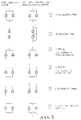
Ein Ausführungsbeispiel der Erfindung ist in der Zeichnung dargestellt und wird im folgenden näher beschrieben. Es zeigen:
- Fig. 1
- eine Seitenansicht der Pumpe auf die flache Seitenwand und
- Fig. 2
- einen axialen Schnitt durch die Pumpe bei nicht geschnittenem Motor,
- Fig. 3
- verschieden Anwendungsfälle der erfindungsgemäßen Pumpe.
- Fig. 1
- a side view of the pump on the flat side wall and
- Fig. 2
- an axial section through the pump with the motor not cut,
- Fig. 3
- different applications of the pump according to the invention.
Die Doppelpumpe weist zwei Spaltrohrpumpen auf und kann als Warmwasserpumpe, insbesondere in Heizungsanlagen eingesetzt werden. Die Pumpe 1 besitzt ein Pumpengehäuse 2, insbesondere aus Kunststoff oder Metall, in dem zwei Laufräder achsparallel angeordnet sind und in dem ein rohrförmiger Einlaß achsial eingeformt ist. Um die Laufräder herum befindet sich jeweils ein sich spiralfärmig erweiternder Auslaßkanal. Das Gehäuse 2 ist kreisscheibenförmig, wobei die Höhe H der zylindrischen Außenwand wesentlich geringer ist als der Durchmesser D der kreisförmigen ebenen, flachen Pumpenseitenwand. 6.The double pump has two canned pumps and can be used as a hot water pump, especially in heating systems. The
In der Seitenwand 6 münden die Einlässe 7 und 8 mit den Einlaßöffnungen 7, 8 und der Auslaßkanal mit einer Auslaßöffnung 4. Die Öffnungen 4, 7 und 8 befinden sich in der Ebene der Seitenwand 6. Auf der der Seitenwand 6 gegenüberliegenden Seite des Pumpengehäuses 2 sind zwei Spaltrohr-Elektromotoren 9 koaxial zu den Laufrädern befestigt.The
Das Pumpengehäuse 2 besitzt einen inneren Einsatz 3, der die Laufräder eng umgibt und die spiralförmig erweiternde Auslaßkanäle um die Laufräder herum bildet, und einen den Einsatz 3 umgebendes Außengehäuse 11, das an den Elektromotoren 9 befestigt ist und das Dichtungen 13 trägt, die in der Ebene der Seitenwand 6 liegen. Der Einsatz 3 bildet somit zusammen mit dem Gehäuserand die ebene Schnittstelle zu den Verbrauchs- oder Anschlußvorrichtungen. Besonders vorteilhaft ist es, daß die Öffnung 5 in der flachen Seitenwand 6 für den Einsatz 3 kreisförmig ist und in einen zylindrischen Innenraum 2a des Pumpengehäuses übergeht.The
Das als Druckbehälter wirkende Außengehäuse 11 bildet parallel zur Seitenwand 6 Flansche 12 aus, die Bohrungen 14 besitzen, um Schrauben aufnehmen zu können. Mit diesen nicht dargestellten Schrauben ist das Außengehäuse 11 und damit die gesamte Pumpe an Verbrauchsvorrichtungen befestigbar. In dieses Außengehäuse 11 können Laufräder 3 und Einsätze 3 unterschiedlicher Leistungen und Bauweisen eingeschoben werden.The outer housing 11, which acts as a pressure vessel, forms
Hierzu können nicht nur die Laufräder durch unterschiedlich geformte Laufräder ersetzt werden, sondern es können auch die Laufräder umgebenden spiralförmigen Kanäle als auch der Einlaß an die jeweiligen Laufräder und die gewünschte Leistung als auch an den jeweiligen Drehzahlbereich angepaßt sein. Ferner können die im Einsatz 3 befindlichen Einlaß- und Auslaßöffnungen 4, 7, 8 in ihrem Abstand zueinander, als auch in ihrer Anordnung in der ebenen Seitenwand 6, an die Gegebenheiten der Verbrauchs- oder Anschlußvorrichtungen angepaßt sein. Es genügt, den Einsatz 3 zu wechseln. um den gestellten Anforderungen gerecht zu werden.For this purpose, not only can the impellers be replaced by differently shaped impellers, but also the spiral channels surrounding the impellers and the inlet can be adapted to the respective impellers and the desired power as well as to the respective speed range be. Furthermore, the inlet and
Die Kanäle können im Einsatz 3 unterschiedlich geformt, als auch angeordnet sein Asperrorgane 4 z.b. Umschlagklappen oder Rückschlagventile befestigt (gelagert) sein, die dem jeweiligen Einsatzzweck entsprechen.The channels can be shaped differently in the
Der innere Einsatz 3 kann kleiner als in den Figuren dargestellt ausgeführt sein. Es kann ausreichen, wenn er nur die Einlaßöffnung 7 und den Leitapparat für das Laufrad bildet. Der Einsatz 3 kann auch aus mehreren Teilen bestehen. Besonders einfach in der Herstellung ist er dann, wenn er aus Kunststoff besteht. Insbesondere hierdurch wird es möglich und wirtschaftlich vertretbar, der Pumpe verschieden geformte Einsätze beizulegen, so daß der Anwender vor dem Einbau die Pumpenfunktion oder -leistung ändern kann.The
Claims (6)
Priority Applications (1)
| Application Number | Priority Date | Filing Date | Title |
|---|---|---|---|
| AT91108395T ATE98000T1 (en) | 1990-07-06 | 1991-05-24 | DOUBLE CENTRIFUGAL PUMP. |
Applications Claiming Priority (2)
| Application Number | Priority Date | Filing Date | Title |
|---|---|---|---|
| DE4021410 | 1990-07-06 | ||
| DE4021410A DE4021410A1 (en) | 1990-07-06 | 1990-07-06 | DOUBLE CENTRIFUGAL PUMP |
Publications (3)
| Publication Number | Publication Date |
|---|---|
| EP0464355A2 true EP0464355A2 (en) | 1992-01-08 |
| EP0464355A3 EP0464355A3 (en) | 1992-02-26 |
| EP0464355B1 EP0464355B1 (en) | 1993-12-01 |
Family
ID=6409706
Family Applications (1)
| Application Number | Title | Priority Date | Filing Date |
|---|---|---|---|
| EP91108395A Expired - Lifetime EP0464355B1 (en) | 1990-07-06 | 1991-05-24 | Duplex centrifugal pump |
Country Status (6)
| Country | Link |
|---|---|
| US (1) | US5178520A (en) |
| EP (1) | EP0464355B1 (en) |
| KR (1) | KR970007394B1 (en) |
| AT (1) | ATE98000T1 (en) |
| DE (2) | DE4021410A1 (en) |
| ES (1) | ES2046823T3 (en) |
Cited By (4)
| Publication number | Priority date | Publication date | Assignee | Title |
|---|---|---|---|---|
| EP0667455A1 (en) * | 1994-02-07 | 1995-08-16 | WILO GmbH | Double pump |
| EP0735272A1 (en) * | 1995-03-28 | 1996-10-02 | WILO GmbH | Centrifugal pump with venting |
| EP1079113A1 (en) * | 1999-08-21 | 2001-02-28 | Grundfos A/S | Centrifugal pump casing for a circulating pump for two fluid circuits |
| DE102018220150A1 (en) * | 2018-11-23 | 2020-05-28 | Mahle International Gmbh | Pump module for coolant |
Families Citing this family (21)
| Publication number | Priority date | Publication date | Assignee | Title |
|---|---|---|---|---|
| US5474431A (en) * | 1993-11-16 | 1995-12-12 | Copeland Corporation | Scroll machine having discharge port inserts |
| DE19702477B4 (en) * | 1997-01-24 | 2006-02-02 | Wilo Ag | double pump |
| US6543243B2 (en) | 2001-06-21 | 2003-04-08 | Visteon Global Technologies, Inc. | Hybrid compressor |
| AU2003200332B2 (en) * | 2002-02-08 | 2005-11-17 | Sanden Corporation | Hybrid compressor |
| FR2893092B1 (en) * | 2005-11-08 | 2008-10-10 | Koyo Hpi Soc Par Actions Simpl | ELECTRO-PUMP GROUP, OF THE TYPE COMPRISING AT LEAST ONE HYDRAULIC PUMP, IN PARTICULAR A GEAR, DRIVEN IN ROTATION BY A MOTOR DEVICE |
| US7507066B2 (en) * | 2006-03-27 | 2009-03-24 | Koenig Kevin J | Pump header body and modular manifold |
| DE102011116957A1 (en) * | 2011-10-26 | 2013-05-02 | Vaillant Gmbh | Multiple coaxial pump |
| DE102012204212B4 (en) * | 2012-03-16 | 2024-02-29 | Mahle International Gmbh | Pump module with a housing |
| US9562534B2 (en) | 2012-05-04 | 2017-02-07 | Ghsp, Inc. | In-line dual pump and motor with control device |
| US9115720B2 (en) | 2012-05-04 | 2015-08-25 | Ghsp, Inc. | Dual pump and motor with control device |
| US9752590B2 (en) * | 2013-03-13 | 2017-09-05 | Ghsp, Inc. | Two pump design with coplanar interface surface |
| US9739284B2 (en) * | 2013-11-19 | 2017-08-22 | Charles Wayne Zimmerman | Two piece impeller centrifugal pump |
| US11015585B2 (en) | 2014-05-01 | 2021-05-25 | Ghsp, Inc. | Submersible pump assembly |
| US10087927B2 (en) | 2014-05-01 | 2018-10-02 | Ghsp, Inc. | Electric motor with flux collector |
| US10711788B2 (en) | 2015-12-17 | 2020-07-14 | Wayne/Scott Fetzer Company | Integrated sump pump controller with status notifications |
| CN110177949A (en) | 2017-01-27 | 2019-08-27 | 塞阿姆斯特朗有限公司 | Binary variable duty ratio performance optimizes pump unit |
| CA172776S (en) | 2017-01-27 | 2017-10-23 | S A Armstrong Ltd | Control pump |
| USD893552S1 (en) | 2017-06-21 | 2020-08-18 | Wayne/Scott Fetzer Company | Pump components |
| USD890211S1 (en) | 2018-01-11 | 2020-07-14 | Wayne/Scott Fetzer Company | Pump components |
| USD940205S1 (en) * | 2019-11-06 | 2022-01-04 | Leistritz Pumpen Gmbh | Pump for liquids |
| RU196491U1 (en) * | 2019-12-18 | 2020-03-03 | Сергей Викторович Яблочко | Two-section electric pump unit |
Citations (3)
| Publication number | Priority date | Publication date | Assignee | Title |
|---|---|---|---|---|
| CH557473A (en) * | 1973-08-28 | 1974-12-31 | Bieri Pumpenbau Ag | Pumping unit for central heating systems - has two independent separately driven rotary pumps which are connected to a common inlet and outlet |
| DE2808741A1 (en) * | 1978-03-01 | 1979-09-06 | Loewe Pumpenfabrik Gmbh | Casing section for rotary pump - has flexible plastics inner part supported in rigid metal outer section |
| DE3624917A1 (en) * | 1985-09-21 | 1987-03-26 | Oplaender Wilo Werk Gmbh | CENTRIFUGAL PUMP |
Family Cites Families (10)
| Publication number | Priority date | Publication date | Assignee | Title |
|---|---|---|---|---|
| US2810345A (en) * | 1953-02-12 | 1957-10-22 | Flygts Pumpar Ab | Pump device |
| DE1715520U (en) * | 1955-11-11 | 1956-01-19 | Kloeckner Humboldt Deutz Ag | CENTRIFUGAL FIRE PUMP. |
| US3500755A (en) * | 1968-05-17 | 1970-03-17 | Crane Co | Combined drag pump and electric motor |
| FR2186123A5 (en) * | 1972-05-26 | 1974-01-04 | Materiel Telephonique | |
| DE2235505B1 (en) * | 1972-07-20 | 1973-12-20 | Klein, Schanzlin & Becker Ag, 6710 Frankenthal | DOUBLE PUMP UNIT |
| FR2408739A1 (en) * | 1977-11-10 | 1979-06-08 | Materiel Telephonique | MONOBLOC PUMPING DEVICE WITH AMBIVALENT OPERATION |
| US4178131A (en) * | 1978-08-07 | 1979-12-11 | Roy E. Roth Company | Centrifugal impellers |
| US4738584A (en) * | 1986-07-28 | 1988-04-19 | Carl Price | Multiple impeller pump |
| US5020420A (en) * | 1989-05-16 | 1991-06-04 | Lamar Ellis | Vacuum adapter plate |
| US5076758A (en) * | 1990-07-18 | 1991-12-31 | Ingersoll-Rand Company | Centrifugal pumps |
-
1990
- 1990-07-06 DE DE4021410A patent/DE4021410A1/en not_active Withdrawn
-
1991
- 1991-05-24 EP EP91108395A patent/EP0464355B1/en not_active Expired - Lifetime
- 1991-05-24 ES ES199191108395T patent/ES2046823T3/en not_active Expired - Lifetime
- 1991-05-24 AT AT91108395T patent/ATE98000T1/en not_active IP Right Cessation
- 1991-05-24 DE DE91108395T patent/DE59100652D1/en not_active Expired - Fee Related
- 1991-06-20 US US07/718,552 patent/US5178520A/en not_active Expired - Fee Related
- 1991-06-28 KR KR1019910010965A patent/KR970007394B1/en not_active IP Right Cessation
Patent Citations (3)
| Publication number | Priority date | Publication date | Assignee | Title |
|---|---|---|---|---|
| CH557473A (en) * | 1973-08-28 | 1974-12-31 | Bieri Pumpenbau Ag | Pumping unit for central heating systems - has two independent separately driven rotary pumps which are connected to a common inlet and outlet |
| DE2808741A1 (en) * | 1978-03-01 | 1979-09-06 | Loewe Pumpenfabrik Gmbh | Casing section for rotary pump - has flexible plastics inner part supported in rigid metal outer section |
| DE3624917A1 (en) * | 1985-09-21 | 1987-03-26 | Oplaender Wilo Werk Gmbh | CENTRIFUGAL PUMP |
Cited By (4)
| Publication number | Priority date | Publication date | Assignee | Title |
|---|---|---|---|---|
| EP0667455A1 (en) * | 1994-02-07 | 1995-08-16 | WILO GmbH | Double pump |
| EP0735272A1 (en) * | 1995-03-28 | 1996-10-02 | WILO GmbH | Centrifugal pump with venting |
| EP1079113A1 (en) * | 1999-08-21 | 2001-02-28 | Grundfos A/S | Centrifugal pump casing for a circulating pump for two fluid circuits |
| DE102018220150A1 (en) * | 2018-11-23 | 2020-05-28 | Mahle International Gmbh | Pump module for coolant |
Also Published As
| Publication number | Publication date |
|---|---|
| KR920002938A (en) | 1992-02-28 |
| ES2046823T3 (en) | 1994-02-01 |
| DE4021410A1 (en) | 1992-01-16 |
| US5178520A (en) | 1993-01-12 |
| KR970007394B1 (en) | 1997-05-08 |
| EP0464355B1 (en) | 1993-12-01 |
| ATE98000T1 (en) | 1993-12-15 |
| DE59100652D1 (en) | 1994-01-13 |
| EP0464355A3 (en) | 1992-02-26 |
Similar Documents
| Publication | Publication Date | Title |
|---|---|---|
| EP0464355B1 (en) | Duplex centrifugal pump | |
| DE2246264C3 (en) | Device to prevent the backflow of centrifugal pumps connected in parallel in a circuit | |
| EP0884479B1 (en) | Feed pump | |
| DE2148574A1 (en) | Vacuum cleaner unit | |
| EP0290033A1 (en) | Homogenising machine for the production of fluid products | |
| DE3545907A1 (en) | ROTARY VALVE | |
| DE60218820T2 (en) | SELF-SUCKING PUMP UNIT | |
| EP2378127B1 (en) | Flow guiding component with pump and fitting | |
| EP0218031B1 (en) | Centrifugal pump | |
| DE4039712C2 (en) | Peripheral pump | |
| EP0694698B1 (en) | Centrifugal pump | |
| DE19749404C1 (en) | Feed pump for motor vehicle fuel tank | |
| DE3821030A1 (en) | CANOPY PUMP | |
| DE3816280C2 (en) | Housing part for centrifugal pumps | |
| EP0735272B1 (en) | Centrifugal pump with venting | |
| DE2845246A1 (en) | Centrifugal pump for central heating applications - has two separate outlets from casing volute for separate circuits to enable independent closure of one circuit | |
| DE1895968U (en) | CIRCULATING PUMP. | |
| WO2019057482A1 (en) | Set of parts and method for producing a radial fan | |
| EP1055826B1 (en) | Valve with replaceable closure element | |
| DE10007072B4 (en) | Multi-way valve and system with such a multi-way valve | |
| EP0849473A1 (en) | Centrifugal pump casing | |
| DE102022213733A1 (en) | centrifugal pump assembly | |
| EP0224755B1 (en) | Stage housing | |
| DE202020006007U1 (en) | check valve | |
| EP0411368A2 (en) | Rotary disk valve |
Legal Events
| Date | Code | Title | Description |
|---|---|---|---|
| PUAI | Public reference made under article 153(3) epc to a published international application that has entered the european phase |
Free format text: ORIGINAL CODE: 0009012 |
|
| PUAL | Search report despatched |
Free format text: ORIGINAL CODE: 0009013 |
|
| AK | Designated contracting states |
Kind code of ref document: A2 Designated state(s): AT BE CH DE DK ES FR GB GR IT LI LU NL SE |
|
| AK | Designated contracting states |
Kind code of ref document: A3 Designated state(s): AT BE CH DE DK ES FR GB GR IT LI LU NL SE |
|
| 17P | Request for examination filed |
Effective date: 19920221 |
|
| RAP1 | Party data changed (applicant data changed or rights of an application transferred) |
Owner name: WILO GMBH |
|
| 17Q | First examination report despatched |
Effective date: 19930205 |
|
| GRAA | (expected) grant |
Free format text: ORIGINAL CODE: 0009210 |
|
| AK | Designated contracting states |
Kind code of ref document: B1 Designated state(s): AT BE CH DE DK ES FR GB GR IT LI LU NL SE |
|
| PG25 | Lapsed in a contracting state [announced via postgrant information from national office to epo] |
Ref country code: GR Free format text: LAPSE BECAUSE OF FAILURE TO SUBMIT A TRANSLATION OF THE DESCRIPTION OR TO PAY THE FEE WITHIN THE PRESCRIBED TIME-LIMIT Effective date: 19931201 Ref country code: DK Effective date: 19931201 Ref country code: SE Effective date: 19931201 |
|
| REF | Corresponds to: |
Ref document number: 98000 Country of ref document: AT Date of ref document: 19931215 Kind code of ref document: T |
|
| GBT | Gb: translation of ep patent filed (gb section 77(6)(a)/1977) |
Effective date: 19931209 |
|
| REF | Corresponds to: |
Ref document number: 59100652 Country of ref document: DE Date of ref document: 19940113 |
|
| ITF | It: translation for a ep patent filed |
Owner name: SOCIETA' ITALIANA BREVETTI S.P.A. |
|
| REG | Reference to a national code |
Ref country code: ES Ref legal event code: FG2A Ref document number: 2046823 Country of ref document: ES Kind code of ref document: T3 |
|
| ET | Fr: translation filed | ||
| PG25 | Lapsed in a contracting state [announced via postgrant information from national office to epo] |
Ref country code: LI Effective date: 19940531 Ref country code: LU Free format text: LAPSE BECAUSE OF NON-PAYMENT OF DUE FEES Effective date: 19940531 Ref country code: CH Effective date: 19940531 |
|
| PLBE | No opposition filed within time limit |
Free format text: ORIGINAL CODE: 0009261 |
|
| STAA | Information on the status of an ep patent application or granted ep patent |
Free format text: STATUS: NO OPPOSITION FILED WITHIN TIME LIMIT |
|
| 26N | No opposition filed | ||
| REG | Reference to a national code |
Ref country code: CH Ref legal event code: PL |
|
| PGFP | Annual fee paid to national office [announced via postgrant information from national office to epo] |
Ref country code: AT Payment date: 19960430 Year of fee payment: 6 |
|
| PGFP | Annual fee paid to national office [announced via postgrant information from national office to epo] |
Ref country code: NL Payment date: 19960529 Year of fee payment: 6 |
|
| PGFP | Annual fee paid to national office [announced via postgrant information from national office to epo] |
Ref country code: BE Payment date: 19960531 Year of fee payment: 6 |
|
| PG25 | Lapsed in a contracting state [announced via postgrant information from national office to epo] |
Ref country code: AT Effective date: 19970524 |
|
| PG25 | Lapsed in a contracting state [announced via postgrant information from national office to epo] |
Ref country code: BE Effective date: 19970531 |
|
| BERE | Be: lapsed |
Owner name: WILO G.M.B.H. Effective date: 19970531 |
|
| PG25 | Lapsed in a contracting state [announced via postgrant information from national office to epo] |
Ref country code: NL Effective date: 19971201 |
|
| NLV4 | Nl: lapsed or anulled due to non-payment of the annual fee |
Effective date: 19971201 |
|
| REG | Reference to a national code |
Ref country code: GB Ref legal event code: IF02 |
|
| PGFP | Annual fee paid to national office [announced via postgrant information from national office to epo] |
Ref country code: ES Payment date: 20020510 Year of fee payment: 12 |
|
| PG25 | Lapsed in a contracting state [announced via postgrant information from national office to epo] |
Ref country code: ES Free format text: LAPSE BECAUSE OF NON-PAYMENT OF DUE FEES Effective date: 20030526 |
|
| REG | Reference to a national code |
Ref country code: ES Ref legal event code: FD2A Effective date: 20030526 |
|
| PGFP | Annual fee paid to national office [announced via postgrant information from national office to epo] |
Ref country code: DE Payment date: 20070517 Year of fee payment: 17 |
|
| PGFP | Annual fee paid to national office [announced via postgrant information from national office to epo] |
Ref country code: GB Payment date: 20070523 Year of fee payment: 17 |
|
| PGFP | Annual fee paid to national office [announced via postgrant information from national office to epo] |
Ref country code: IT Payment date: 20070528 Year of fee payment: 17 |
|
| PGFP | Annual fee paid to national office [announced via postgrant information from national office to epo] |
Ref country code: FR Payment date: 20070510 Year of fee payment: 17 |
|
| GBPC | Gb: european patent ceased through non-payment of renewal fee |
Effective date: 20080524 |
|
| REG | Reference to a national code |
Ref country code: FR Ref legal event code: ST Effective date: 20090119 |
|
| PG25 | Lapsed in a contracting state [announced via postgrant information from national office to epo] |
Ref country code: DE Free format text: LAPSE BECAUSE OF NON-PAYMENT OF DUE FEES Effective date: 20081202 Ref country code: FR Free format text: LAPSE BECAUSE OF NON-PAYMENT OF DUE FEES Effective date: 20080602 |
|
| PG25 | Lapsed in a contracting state [announced via postgrant information from national office to epo] |
Ref country code: GB Free format text: LAPSE BECAUSE OF NON-PAYMENT OF DUE FEES Effective date: 20080524 |
|
| PG25 | Lapsed in a contracting state [announced via postgrant information from national office to epo] |
Ref country code: IT Free format text: LAPSE BECAUSE OF NON-PAYMENT OF DUE FEES Effective date: 20080524 |