EP0463358A1 - Method of manufacture of large volume fuel tanks - Google Patents
Method of manufacture of large volume fuel tanks Download PDFInfo
- Publication number
- EP0463358A1 EP0463358A1 EP91108092A EP91108092A EP0463358A1 EP 0463358 A1 EP0463358 A1 EP 0463358A1 EP 91108092 A EP91108092 A EP 91108092A EP 91108092 A EP91108092 A EP 91108092A EP 0463358 A1 EP0463358 A1 EP 0463358A1
- Authority
- EP
- European Patent Office
- Prior art keywords
- membrane
- tank
- panels
- membrane frame
- fuel tanks
- Prior art date
- Legal status (The legal status is an assumption and is not a legal conclusion. Google has not performed a legal analysis and makes no representation as to the accuracy of the status listed.)
- Ceased
Links
Images

Classifications
-
- B—PERFORMING OPERATIONS; TRANSPORTING
- B21—MECHANICAL METAL-WORKING WITHOUT ESSENTIALLY REMOVING MATERIAL; PUNCHING METAL
- B21D—WORKING OR PROCESSING OF SHEET METAL OR METAL TUBES, RODS OR PROFILES WITHOUT ESSENTIALLY REMOVING MATERIAL; PUNCHING METAL
- B21D26/00—Shaping without cutting otherwise than using rigid devices or tools or yieldable or resilient pads, i.e. applying fluid pressure or magnetic forces
- B21D26/02—Shaping without cutting otherwise than using rigid devices or tools or yieldable or resilient pads, i.e. applying fluid pressure or magnetic forces by applying fluid pressure
- B21D26/021—Deforming sheet bodies
-
- B—PERFORMING OPERATIONS; TRANSPORTING
- B21—MECHANICAL METAL-WORKING WITHOUT ESSENTIALLY REMOVING MATERIAL; PUNCHING METAL
- B21D—WORKING OR PROCESSING OF SHEET METAL OR METAL TUBES, RODS OR PROFILES WITHOUT ESSENTIALLY REMOVING MATERIAL; PUNCHING METAL
- B21D26/00—Shaping without cutting otherwise than using rigid devices or tools or yieldable or resilient pads, i.e. applying fluid pressure or magnetic forces
- B21D26/02—Shaping without cutting otherwise than using rigid devices or tools or yieldable or resilient pads, i.e. applying fluid pressure or magnetic forces by applying fluid pressure
- B21D26/053—Shaping without cutting otherwise than using rigid devices or tools or yieldable or resilient pads, i.e. applying fluid pressure or magnetic forces by applying fluid pressure characterised by the material of the blanks
- B21D26/059—Layered blanks
-
- B—PERFORMING OPERATIONS; TRANSPORTING
- B64—AIRCRAFT; AVIATION; COSMONAUTICS
- B64D—EQUIPMENT FOR FITTING IN OR TO AIRCRAFT; FLIGHT SUITS; PARACHUTES; ARRANGEMENTS OR MOUNTING OF POWER PLANTS OR PROPULSION TRANSMISSIONS IN AIRCRAFT
- B64D37/00—Arrangements in connection with fuel supply for power plant
- B64D37/02—Tanks
- B64D37/06—Constructional adaptations thereof
Definitions
- the invention relates to a process for the manufacture of large volume fuel tanks using thermoplastic materials, e.g. for aircraft and rockets according to the generic concept of claim 1.
- thermomechanical stresses between the structure and the tank are reduced by creating changes in the length and shape of the tank wall that are as free as possible.
- Internal pressures are optimally absorbed by preformed membranes, which allows a reduction in the membrane wall thickness.
- thermoplastic deformable materials cut to shape flat membrane panels 10 are welded together at their edges 13 and welded into a membrane frame 11.
- the latter is thermoplastic deformed under the temperature and the internal pressure required for the selected material, as a result of which the membranes are shaped to be optimal in terms of tension.
- the tank then undergoes a cooling process under an internal pressure in which the shape obtained is retained.
- the tank cross-section is easily adaptable to the aircraft design 101 for an LH3 membrane tank.
- this manufacturing process is particularly suitable for superplastic or hot plastic deformable materials, especially for titanium alloys and if the degrees of deformation are not significantly higher than 10% also for other materials.
Abstract
Description
Die Erfindung bezieht sich auf ein Verfahren zur Herstellung großvolumiger Treibstofftanks unter Verwendung warmplastisch verformbarer Materialien, z.B. für Flugzeuge und Raketen gemäß dem Gattungsbgeriff des Anspruchs 1.The invention relates to a process for the manufacture of large volume fuel tanks using thermoplastic materials, e.g. for aircraft and rockets according to the generic concept of claim 1.
Für die Triebwerke von Hochleistungsflugzeugen, insbesondere von solchen der sogenannten SÄNGER-Unter- und Oberstufe sind als Energieträger Wasserstoff und Sauerstoff vorgesehen. Hierbei müssen für die Oberstufe beide Stoffe und für die Unterstufe nur Wasserstoff in flüssiger Form in entsprechenden Tanks gespeichert und mitgeführt werden. Nun ergeben sich aufgrund der relativ geringen Dichte des flüssigen Wasserstoffes sehr große Volumenerfordernisse für die Tanks, die in einem vorliegenden Fall ungefähr 1.600 m³ betragen. Es ist daher leicht verständlich, daß solche voluminösen Bauteile einen entscheidenden Einfluß auf das Strukturkonzept des Flugzeugrumpfes ausüben. Hinzu kommt noch, daß solche Flüssigwasserstofftanks wegen der SÄNGER-spezifischen technischen Randbedingungen und die erforderlichen Wärmedämmungen äußerst kritische Bauteile darstellen.For the engines of high-performance aircraft, especially those of the so-called SÄNGER lower and upper stages, hydrogen and oxygen are provided as energy sources. Both substances have to be stored in the appropriate tanks for the upper stage and only hydrogen in liquid form for the lower stage. Now, due to the relatively low density of the liquid hydrogen, there are very large volume requirements for the tanks, which in this case are approximately 1,600 m³. It is therefore easy to understand that such voluminous components have a decisive influence on the structural concept of the fuselage. In addition, such liquid hydrogen tanks are extremely critical components due to the SÄNGER-specific technical boundary conditions and the required thermal insulation.
Ein Aufbau des Tanks aus gewölbten Membranformen ermöglicht eine Reduktion der Wandstärken und damit des Gewichtes, da die gewölbten Membranformen eine im Betriebsfall nahezu spannungsoptimale Form haben können.Building the tank out of curved membrane shapes enables a reduction in the wall thicknesses and thus the weight, since the curved membrane shapes can have an almost stress-optimal shape in operation.
Aus der DE-OS 30 45 417 ist ein Verbundmaterial zur Herstellung von Behältern mit biegsamen Wandungen bekanntgeworden, das sich aus Geweben und Garnen zusammensetzt. Für die Verwendung zur Herstellung der eingangs genannten Tanks ist dieses Material jedoch nicht geeignet.From DE-OS 30 45 417 a composite material for the production of containers with flexible walls has become known, which is composed of fabrics and yarns. However, this material is not suitable for use in the manufacture of the tanks mentioned at the outset.
Aus der DE-OS 31 04 919 ist ein Verfahren zur Herstellung metallischer Gegenstände aus superplastisch deformierbarem Material bekanntgeworden, wobei die verwendeten Bleche auf einen Temperaturbereich aufgeheizt werden, in dem eine superplastische Deformation erfolgt und dann diese Bleche unter Anwendung eines Gasdruckes an bestimmten Stellen gegeneinander gepreßt werden, wobei die sich berührenden Stellen dann miteinander verbunden werden. Dieses Verfahren ist zur Herstellung von großvolumigen Flugzeug- und Treibstofftanks nicht geeignet, denn durch die dann erforderlichen zahlreichen Naht-Schweißungen werden hohe Materialspannungen in die Tankhaut eingebracht, die zu bald auftretenden Rißbildungen und Materialermüdungen führen.From DE-OS 31 04 919 a process for the production of metallic objects from superplastic deformable material has become known, the sheets used being heated to a temperature range in which a superplastic deformation takes place and then this Sheets are pressed against one another at certain points using a gas pressure, the contacting points then being connected to one another. This process is not suitable for the production of large-volume aircraft and fuel tanks, because the numerous seam welds that are then required bring high material stresses into the tank skin, which can lead to cracking and material fatigue.
Der vorliegenden Erfindung liegt die Aufgabe zugrunde, ein Verfahren der eingangs genannten Art aufzuzeigen, bei dem die durch die Verformungen und die Verschweißungen auftretenden Restspannungen im Tanksystem weitgehend eliminiert und die Tankgesamtgewichte sowie die Sicherheit und Lebensdauer wesentlich erhöht sind,
Diese Aufgabe wird durch die im Anspruch 1 aufgezeigten Maßnahmen gelöst. In den Unteransprüchen sind Ausgestaltungen und Weiterbildungen angegeben und in der nachfolgenden Beschreibung ist ein Ausführungsbeispiel erläutert. Auch die Figuren der Zeichung dienen der näheren Erläuterung. Es zeigen:
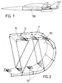
- Fig. 1
- ein Schemabild einer Seitenansicht eines Flugzeugs mit Triebwerken der SÄNGER-Unter- und Oberstufe mit LH²-Treibstofftank,
- Fig. 2
- eine perspektivische Teilansicht eines halben Tankquerschnittes einer Breite eines Membranstreifens,
- Fig. 3
- einen Oberflächenausschnitt des Membrantanks.
This object is achieved by the measures indicated in claim 1. Refinements and developments are specified in the subclaims and an exemplary embodiment is explained in the following description. The figures in the drawing also serve for a more detailed explanation. Show it:
- Fig. 1
- a schematic image of a side view of an aircraft with engines of the SÄNGER lower and upper stage with LH² fuel tank,
- Fig. 2
- 2 shows a perspective partial view of a half tank cross section with a width of a membrane strip,
- Fig. 3
- a surface cutout of the membrane tank.
Der allgemeine Erfindungsgedanke, der dem nachfolgend beschriebenen Ausführungsbeispiel zugrundeliegt, stellt eine Reduktion der thermomechanischen Spannungen zwischen Struktur und Tank durch Schaffung möglichst freier Längen- und Formänderungen der Tankwand sicher. Innendrücke werden spannungsoptimal durch vorgeformte Membranen aufgenommen, was eine Reduktion der Membranwandstärken erlaubt. Hierzu wird nun vorgeschlagen, daß unter Verwendung warmplastischer verformbarer Materialien auf Form geschnittene plane Membranpaneele 10 an ihren Rändern 13 miteinander verschweißt und in einen Membran-Rahmen 11 eingeschweißt werden. Nach Fertigstellung des Tanks 100 wird dieser unter der für das gewählte Material erforderlichen Temperatur und dem erforderlichen Innendruck warmplastisch verformt, wodurch eine spannungsoptimale Form der Membranen erreicht wird. Anschließend erfährt der Tank einen Abkühlprozeß unter einem Innendruck, bei dem die erzielte Form erhalten bleibt.The general inventive concept on which the exemplary embodiment described below is based ensures that the thermomechanical stresses between the structure and the tank are reduced by creating changes in the length and shape of the tank wall that are as free as possible. Internal pressures are optimally absorbed by preformed membranes, which allows a reduction in the membrane wall thickness. For this now proposed that using thermoplastic deformable materials cut to shape
Durch dieses Verfahren werden die zwangsläufig auftretenden Restspannungen, hervorgerufen durch Membranumformung und Verschweißung, weitgehend vermindert. Die Schweißverzüge der planen Membranpaneele können bei der Schweißnaht zur vollständigen Schließung des Treibstofftanks wesentlich leichter korrigiert werden als bei gekrümmten Membranpaneelen. Aus Dichtheitsgründen müssen nämlich die sehr dünnwandigen und in ihrer Mitte typischerweise nur etwa 0,5 mm Dicke betragenden Membranpaneele 10 an den Stoßstellen zur Innenstrukturbildung geschweißt werden. Aufgrund der Vielzahl der Schweißnähte, die oft eine Gesamtlänge von mehreren Kilometern erreichen, und vor allem der Überkreuzungspunkte mit den Membranstützen 12 werden hohe Materialspannungen in die Tankhaut eingebracht. Dies führt - wie bereits angeführt - unweigerlich zu beschleunigten Rißbildungen bzw. zu Materialermüdungen. Diese Gefahr ist aber nunmehr durch die oben vorgeschlagenen Maßnahmen beseitigt worden.This procedure largely reduces the inevitable residual stresses caused by membrane forming and welding. The welding distortions of the flat membrane panels can be corrected much more easily in the weld seam to completely close the fuel tank than in the case of curved membrane panels. For reasons of tightness, the very thin-
Kaltverformung der Membranelemente 10 ist für Al-Bleche möglich, wobei allerdings keine hohen und erforderlichen Formgenauigkeiten aufgrund der Rückfederung entsprechend der Blechdickentoleranz erreicht werden. Entsprechend dem Umformgrad verbleiben Spannungen in den Blechen, die nach dem Paneel-Zuschnitt jedoch zu Formabweichungen führen.Cold deformation of the
Es zeigt sich also, daß sowohl durch die Vorformung der Membranen wie durch den Schweißprozeß zum Teil beträchtliche Restspannungen im Tank auftreten, welche die Sicherheit während der Lebensdauer von ca. 20 Jahren nachteilig beeinflussen. Dies ist jedoch durch das vorgeschlagene Verfahren - wie bereits ausgeführt - weitestgehend beseitigt worden.It can thus be seen that both the preforming of the membranes and the welding process sometimes result in considerable residual stresses in the tank, which adversely affect safety over the life of approximately 20 years. However, as already explained, this has largely been eliminated by the proposed method.
Durch den fachwerkartig ausgebildeten Membranrahmen 11, der an jedem Schnitt- bzw. Kreuzungspunkt mit einer Membranstütze 12 versehen ist, wobei sowohl die Verteilung der Wandstärken der Membranpaneele 10 als auch die Temperaturverteilung über diesen Paneelen inhomogen sein kann, ist ein an die Flugzeugkonzeption leicht anpaßbarer Tankinnenquerschnitt 101 für einen LH³-Membrantank geschaffen worden. Hierbei ist dieses Fertigungsverfahren für superplastisch bzw. warmplastisch verformbare Materialien besonders geeignet und zwar besonders für Titanlegierungen und wenn die Umformgrade nicht wesentlich höher als 10% betragen auch für andere Werkstoffe.Due to the truss-
Claims (8)
Applications Claiming Priority (2)
| Application Number | Priority Date | Filing Date | Title |
|---|---|---|---|
| DE4020850 | 1990-06-29 | ||
| DE19904020850 DE4020850A1 (en) | 1990-06-29 | 1990-06-29 | METHOD FOR THE PRODUCTION OF LARGE VOLUME FUEL TANKS |
Publications (1)
| Publication Number | Publication Date |
|---|---|
| EP0463358A1 true EP0463358A1 (en) | 1992-01-02 |
Family
ID=6409406
Family Applications (1)
| Application Number | Title | Priority Date | Filing Date |
|---|---|---|---|
| EP91108092A Ceased EP0463358A1 (en) | 1990-06-29 | 1991-05-18 | Method of manufacture of large volume fuel tanks |
Country Status (2)
| Country | Link |
|---|---|
| EP (1) | EP0463358A1 (en) |
| DE (1) | DE4020850A1 (en) |
Cited By (2)
| Publication number | Priority date | Publication date | Assignee | Title |
|---|---|---|---|---|
| FR2953194A1 (en) * | 2009-11-30 | 2011-06-03 | Airbus Operations Sas | Aircraft i.e. aerodyne, has sections that are arranged such that angle is obtained by specific relationship comprising parameters such as distances between cores of intermediate unit, where distances are different from each other |
| CN112278298A (en) * | 2020-10-20 | 2021-01-29 | 北京机电工程研究所 | Bionic aircraft oil tank |
Families Citing this family (1)
| Publication number | Priority date | Publication date | Assignee | Title |
|---|---|---|---|---|
| DE102014102254A1 (en) * | 2014-02-21 | 2015-08-27 | Dr. Ing. H.C. F. Porsche Aktiengesellschaft | Method of manufacturing a fuel tank and fuel tank |
Citations (5)
| Publication number | Priority date | Publication date | Assignee | Title |
|---|---|---|---|---|
| DE1901767A1 (en) * | 1969-01-15 | 1970-07-30 | Atlas Mak Maschb Gmbh | Explosive forming of non-ferrous materials - in steel container ends |
| DE2426601A1 (en) * | 1973-10-02 | 1975-04-10 | Alter Licensing Ets | METHOD OF MANUFACTURING A CONTAINER FROM A SUPERPLASTIC ALLOY BY BLOWING |
| DE2361215A1 (en) * | 1973-12-08 | 1975-06-12 | Volkswagenwerk Ag | Closed container made from two sheet metal plates - which are simultaneously formed on single press tool |
| US4026503A (en) * | 1974-12-19 | 1977-05-31 | British Aircraft Corporation Limited | Fuel storage means |
| EP0138120A2 (en) * | 1983-09-30 | 1985-04-24 | The Boeing Company | A truss supporting structure for a toroidal tank |
Family Cites Families (4)
| Publication number | Priority date | Publication date | Assignee | Title |
|---|---|---|---|---|
| US2579646A (en) * | 1947-06-30 | 1951-12-25 | Mcnamar Boiler & Tank Company | Method of forming spherical containers |
| US2503191A (en) * | 1947-06-30 | 1950-04-04 | Mcnamar Boiler & Tank Company | Method of forming tanks of spherical configuration |
| DE3104919A1 (en) * | 1980-02-15 | 1981-12-17 | British Aerospace Public Ltd. Co., London | METHOD FOR PRODUCING METAL ITEMS |
| DE3045417A1 (en) * | 1980-12-02 | 1982-08-19 | Goodyear Aerospace Corp., 44316 Akron, Ohio | Fabric reinforced composite for making container - and nonionic surfactant as stabilisers |
-
1990
- 1990-06-29 DE DE19904020850 patent/DE4020850A1/en active Granted
-
1991
- 1991-05-18 EP EP91108092A patent/EP0463358A1/en not_active Ceased
Patent Citations (5)
| Publication number | Priority date | Publication date | Assignee | Title |
|---|---|---|---|---|
| DE1901767A1 (en) * | 1969-01-15 | 1970-07-30 | Atlas Mak Maschb Gmbh | Explosive forming of non-ferrous materials - in steel container ends |
| DE2426601A1 (en) * | 1973-10-02 | 1975-04-10 | Alter Licensing Ets | METHOD OF MANUFACTURING A CONTAINER FROM A SUPERPLASTIC ALLOY BY BLOWING |
| DE2361215A1 (en) * | 1973-12-08 | 1975-06-12 | Volkswagenwerk Ag | Closed container made from two sheet metal plates - which are simultaneously formed on single press tool |
| US4026503A (en) * | 1974-12-19 | 1977-05-31 | British Aircraft Corporation Limited | Fuel storage means |
| EP0138120A2 (en) * | 1983-09-30 | 1985-04-24 | The Boeing Company | A truss supporting structure for a toroidal tank |
Cited By (2)
| Publication number | Priority date | Publication date | Assignee | Title |
|---|---|---|---|---|
| FR2953194A1 (en) * | 2009-11-30 | 2011-06-03 | Airbus Operations Sas | Aircraft i.e. aerodyne, has sections that are arranged such that angle is obtained by specific relationship comprising parameters such as distances between cores of intermediate unit, where distances are different from each other |
| CN112278298A (en) * | 2020-10-20 | 2021-01-29 | 北京机电工程研究所 | Bionic aircraft oil tank |
Also Published As
| Publication number | Publication date |
|---|---|
| DE4020850C2 (en) | 1992-06-17 |
| DE4020850A1 (en) | 1992-01-09 |
Similar Documents
| Publication | Publication Date | Title |
|---|---|---|
| DE2432929C3 (en) | Method of bending a sandwich panel | |
| DE3314264A1 (en) | METHOD FOR PRODUCING STEEL COMPOSITE TUBES | |
| DE1264160B (en) | Liquid-cooled components such as rocket combustion chambers and processes for their manufacture | |
| DE2616448A1 (en) | COMPOSITE METAL OBJECTS AND THE PROCESS FOR THEIR MANUFACTURING | |
| DE2747186A1 (en) | MODULAR GETTER PUMP | |
| CH661232A5 (en) | METHOD FOR DIFFUSION WELDING. | |
| DE19915082C1 (en) | Regeneratively cooled rocket motor nozzle comprizes spiraled coolant-flowed tubing subsequently sprayed with loadbearing and fixing layers once exterior mandrel former is stripped off. | |
| EP0082920B1 (en) | Metal tank, particularly in chemical apparatus constructions, and process for manufacturing such a tank | |
| DE2543970A1 (en) | PRE-SHAPING OF A CLADDING PLATE FOR A CONVEX-CONCAVE SUBSTRATE | |
| DE102019005917A1 (en) | Method and device for manufacturing a component from a fiber composite material | |
| DE4017691A1 (en) | WELDING SINTERED, FILLED POLYTETRAFLUORAETHYLENE | |
| DE19713963C1 (en) | Fluid guide element | |
| DE2648877B2 (en) | Process for making pipes | |
| DE4341281C1 (en) | Method for the production of parts by superplastic forming | |
| DE1752486B1 (en) | PROCESS FOR GENERATING THE FINAL DIMENSIONS IN THE MANUFACTURE OF A WELDED PRECISION TUBE FOR CORE REACTORS AND THORN FOR EXECUTING THE PROCESS | |
| EP0463358A1 (en) | Method of manufacture of large volume fuel tanks | |
| WO1999001390B1 (en) | Processes and devices for producing glass foils and composite bodies produced therefrom | |
| DE3515323C1 (en) | Substructure for aircraft supporting structures and tail units | |
| DE2638427C2 (en) | Laminate strips and their use as insulation strips in spiral winding devices | |
| EP3016775B1 (en) | Method for producing hollow bodies from heat resistant steel | |
| DE3625755C2 (en) | ||
| DE2648007C3 (en) | Process for diffusion welding of metallic workpieces and use of the process | |
| DE3121126C1 (en) | Device for superplastic deformation | |
| DE102016122603B4 (en) | Process for producing a heat exchanger element and heat exchanger element | |
| DE1752486C (en) | Process for producing the final dimensions in the manufacture of a welded precision tube for nuclear reactors and a mandrel for carrying out the process |
Legal Events
| Date | Code | Title | Description |
|---|---|---|---|
| PUAI | Public reference made under article 153(3) epc to a published international application that has entered the european phase |
Free format text: ORIGINAL CODE: 0009012 |
|
| AK | Designated contracting states |
Kind code of ref document: A1 Designated state(s): AT BE CH DE DK ES FR GB GR IT LI LU NL SE |
|
| 17P | Request for examination filed |
Effective date: 19920627 |
|
| 17Q | First examination report despatched |
Effective date: 19930428 |
|
| STAA | Information on the status of an ep patent application or granted ep patent |
Free format text: STATUS: THE APPLICATION HAS BEEN REFUSED |
|
| 18R | Application refused |
Effective date: 19931120 |