EP0463057B1 - Floating aquatic plant water treatment system - Google Patents
Floating aquatic plant water treatment system Download PDFInfo
- Publication number
- EP0463057B1 EP0463057B1 EP90905008A EP90905008A EP0463057B1 EP 0463057 B1 EP0463057 B1 EP 0463057B1 EP 90905008 A EP90905008 A EP 90905008A EP 90905008 A EP90905008 A EP 90905008A EP 0463057 B1 EP0463057 B1 EP 0463057B1
- Authority
- EP
- European Patent Office
- Prior art keywords
- grid
- segments
- floating
- fold
- water
- Prior art date
- Legal status (The legal status is an assumption and is not a legal conclusion. Google has not performed a legal analysis and makes no representation as to the accuracy of the status listed.)
- Expired - Lifetime
Links
- XLYOFNOQVPJJNP-UHFFFAOYSA-N water Substances O XLYOFNOQVPJJNP-UHFFFAOYSA-N 0.000 title claims abstract description 95
- 238000007667 floating Methods 0.000 title claims abstract description 62
- 230000004888 barrier function Effects 0.000 claims description 17
- 238000005188 flotation Methods 0.000 claims description 17
- 239000002028 Biomass Substances 0.000 claims description 14
- 238000000034 method Methods 0.000 claims description 8
- 230000002441 reversible effect Effects 0.000 claims description 5
- 210000002457 barrier cell Anatomy 0.000 claims description 2
- 210000004027 cell Anatomy 0.000 claims 3
- 241000196324 Embryophyta Species 0.000 description 55
- 239000007921 spray Substances 0.000 description 18
- 239000000463 material Substances 0.000 description 14
- 238000010276 construction Methods 0.000 description 12
- 239000002351 wastewater Substances 0.000 description 11
- 238000004065 wastewater treatment Methods 0.000 description 11
- 235000015097 nutrients Nutrition 0.000 description 10
- 238000003306 harvesting Methods 0.000 description 8
- 241000209499 Lemna Species 0.000 description 7
- 244000207740 Lemna minor Species 0.000 description 7
- 239000003344 environmental pollutant Substances 0.000 description 6
- 231100000719 pollutant Toxicity 0.000 description 6
- 235000006439 Lemna minor Nutrition 0.000 description 5
- 235000001855 Portulaca oleracea Nutrition 0.000 description 5
- 239000000835 fiber Substances 0.000 description 5
- 238000005507 spraying Methods 0.000 description 5
- 238000004804 winding Methods 0.000 description 5
- 230000009471 action Effects 0.000 description 3
- 230000008901 benefit Effects 0.000 description 3
- 239000000428 dust Substances 0.000 description 3
- 244000005700 microbiome Species 0.000 description 3
- 239000011148 porous material Substances 0.000 description 3
- 241000607479 Yersinia pestis Species 0.000 description 2
- 230000007704 transition Effects 0.000 description 2
- 244000307697 Agrimonia eupatoria Species 0.000 description 1
- 235000016626 Agrimonia eupatoria Nutrition 0.000 description 1
- 241000758794 Asarum Species 0.000 description 1
- 241001532704 Azolla Species 0.000 description 1
- 241000894006 Bacteria Species 0.000 description 1
- 240000003826 Eichhornia crassipes Species 0.000 description 1
- 244000052355 Hydrilla verticillata Species 0.000 description 1
- 235000003283 Pachira macrocarpa Nutrition 0.000 description 1
- 244000207867 Pistia stratiotes Species 0.000 description 1
- 235000006440 Pistia stratiotes Nutrition 0.000 description 1
- 240000001085 Trapa natans Species 0.000 description 1
- 235000014364 Trapa natans Nutrition 0.000 description 1
- 231100000693 bioaccumulation Toxicity 0.000 description 1
- 230000005465 channeling Effects 0.000 description 1
- 238000004140 cleaning Methods 0.000 description 1
- 239000004035 construction material Substances 0.000 description 1
- 239000000356 contaminant Substances 0.000 description 1
- 230000003247 decreasing effect Effects 0.000 description 1
- 230000000994 depressogenic effect Effects 0.000 description 1
- 238000007865 diluting Methods 0.000 description 1
- 230000007613 environmental effect Effects 0.000 description 1
- 239000003337 fertilizer Substances 0.000 description 1
- 239000002657 fibrous material Substances 0.000 description 1
- 235000013305 food Nutrition 0.000 description 1
- 229910052751 metal Inorganic materials 0.000 description 1
- 239000002184 metal Substances 0.000 description 1
- 150000002739 metals Chemical class 0.000 description 1
- 230000000813 microbial effect Effects 0.000 description 1
- 235000016709 nutrition Nutrition 0.000 description 1
- 239000002245 particle Substances 0.000 description 1
- 230000008569 process Effects 0.000 description 1
- 230000003014 reinforcing effect Effects 0.000 description 1
- 230000008439 repair process Effects 0.000 description 1
- 235000009165 saligot Nutrition 0.000 description 1
- 238000012216 screening Methods 0.000 description 1
- 239000002364 soil amendment Substances 0.000 description 1
- 239000007787 solid Substances 0.000 description 1
- 238000003860 storage Methods 0.000 description 1
- 239000002699 waste material Substances 0.000 description 1
- 239000003643 water by type Substances 0.000 description 1
Images






Classifications
-
- C—CHEMISTRY; METALLURGY
- C02—TREATMENT OF WATER, WASTE WATER, SEWAGE, OR SLUDGE
- C02F—TREATMENT OF WATER, WASTE WATER, SEWAGE, OR SLUDGE
- C02F3/00—Biological treatment of water, waste water, or sewage
- C02F3/02—Aerobic processes
- C02F3/06—Aerobic processes using submerged filters
-
- C—CHEMISTRY; METALLURGY
- C02—TREATMENT OF WATER, WASTE WATER, SEWAGE, OR SLUDGE
- C02F—TREATMENT OF WATER, WASTE WATER, SEWAGE, OR SLUDGE
- C02F3/00—Biological treatment of water, waste water, or sewage
- C02F3/02—Aerobic processes
- C02F3/10—Packings; Fillings; Grids
-
- C—CHEMISTRY; METALLURGY
- C02—TREATMENT OF WATER, WASTE WATER, SEWAGE, OR SLUDGE
- C02F—TREATMENT OF WATER, WASTE WATER, SEWAGE, OR SLUDGE
- C02F3/00—Biological treatment of water, waste water, or sewage
- C02F3/32—Biological treatment of water, waste water, or sewage characterised by the animals or plants used, e.g. algae
- C02F3/327—Biological treatment of water, waste water, or sewage characterised by the animals or plants used, e.g. algae characterised by animals and plants
-
- Y—GENERAL TAGGING OF NEW TECHNOLOGICAL DEVELOPMENTS; GENERAL TAGGING OF CROSS-SECTIONAL TECHNOLOGIES SPANNING OVER SEVERAL SECTIONS OF THE IPC; TECHNICAL SUBJECTS COVERED BY FORMER USPC CROSS-REFERENCE ART COLLECTIONS [XRACs] AND DIGESTS
- Y02—TECHNOLOGIES OR APPLICATIONS FOR MITIGATION OR ADAPTATION AGAINST CLIMATE CHANGE
- Y02W—CLIMATE CHANGE MITIGATION TECHNOLOGIES RELATED TO WASTEWATER TREATMENT OR WASTE MANAGEMENT
- Y02W10/00—Technologies for wastewater treatment
- Y02W10/10—Biological treatment of water, waste water, or sewage
-
- Y—GENERAL TAGGING OF NEW TECHNOLOGICAL DEVELOPMENTS; GENERAL TAGGING OF CROSS-SECTIONAL TECHNOLOGIES SPANNING OVER SEVERAL SECTIONS OF THE IPC; TECHNICAL SUBJECTS COVERED BY FORMER USPC CROSS-REFERENCE ART COLLECTIONS [XRACs] AND DIGESTS
- Y02—TECHNOLOGIES OR APPLICATIONS FOR MITIGATION OR ADAPTATION AGAINST CLIMATE CHANGE
- Y02W—CLIMATE CHANGE MITIGATION TECHNOLOGIES RELATED TO WASTEWATER TREATMENT OR WASTE MANAGEMENT
- Y02W10/00—Technologies for wastewater treatment
- Y02W10/30—Wastewater or sewage treatment systems using renewable energies
- Y02W10/33—Wastewater or sewage treatment systems using renewable energies using wind energy
Definitions
- the present invention relates to a biomass producing system and in particular to a wastewater treatment system using floating aquatic plants for removing pollutants as the water passes through the treatment system.
- Floating aquatic plants have been used in the treatment of wastewater and/or for improved water quality, see for example J. Zirschky et al . Journal WP CF, Vol.60, No.7, pp 1253-1258.
- plants of the duckweed and liverwort families, water hyacinths, water chestnuts, water lettuce, heartleaf, hydrillas, and azollas have proven effective for water treatment.
- algal turf formed from microalgae has been used to remove nutrients and other contaminants from polluted waters - see US-A-4 333 263.
- the duckweed family of plants provides for a biomass producing system wherein unwanted nutrients are harvested from aquatic systems by means of bioaccumulation to treat wastewater and/or improve water quality, and the plants are harvested as a cash crop.
- Duckweed is particularly suited to this purpose as it is native to most of the world including the United States and has the capability of rapidly taking up nutrients from an aquatic environment to provide a food source with a high nutritional and protein content.
- the natural development of these plants has produced strains which can grow throughout the year given an open water condition.
- these plants have developed a pest resistance which is missing in most other cash crops. Natural resistance to pests provides for a nearly pesticide-free and herbicide-free operation.
- the present invention solves these and other problems related to using floating aquatic plants and with treatment of wastewater and enabling harvesting as a cash crop, economically.
- the invention provides a buoyant containing grid section for an aquatic biomass containment grid structure, as defined in Claim 4 below.
- the invention also provides a floating aquatic biomass containment barrier cell as set forth in Claim 5, a network of floating aquatic biomass containment barriers as set forth in Claim 6 and a method of deploying a floating point containment system as set forth in Claim 7.
- the floating grids and containment systems of the invention can be used in a system for the treatment of waste water in which a dividing wall, preferably a berm, is used to channel waste water along a winding path wherein pollutants are removed.
- Berms are constructed so that the material removed from the channel and placed on the berms is of approximately equal volume. In this manner, little material is required to be hauled in or away from the waster water treatment area.
- the channel is constructed having parallel straight portions connected by U-turns.
- the channel is constructed such that the flow is between turbulent and laminar flow regimes.
- the channel is also constructed so that the straight portions are perpendicular to the direction of the prevailing wind, thereby reducing the wind fetch, and maximizing the use of berms as a wind break.
- the U-turns may have a curvilinear guide to aid in directing the flow of water around the turn and onto the next straight portion to decrease wearing at the turn.
- the berms will have trees or shrubs planted
- the wastewater treatment channel is preferably constructed in modules so that a portion of the channel may be constructed and used before the remainder of the channel. In this manner where time is important on a construction schedule, a wastewater treatment system can be implemented much faster. Furthermore the winding configuration provides for use of control structures along the channel so that the water may enter or exit the system along an intermediate portion of the channel should the entire channel length not be required.
- the channel includes an access so that a harvester or barge may be launched onto the water and retrieved.
- the winding channel configuration is especially advantageous when combined with a grid containment system for containing duckweed plants used in wastewater treatment.
- the channel may also include baffles extending across the channel to further advantage, as explained hereinafter.
- the channel structure is especially effective when combined with a grid system of the present invention for containing floating aquatic plants used in treating wastewater.
- the floating containment grid structure is constructed of individual grid sections which are reversible and float on the surface of the water.
- the grid sections include flotation chambers so that the grid sections are buoyant and extend above the water to a height sufficient to contain the floating aquatic plants.
- the grid segments may have any length, but are preferably of the same length for a given body of water for interchanging, so that the segments may be easily replaced. The reversibility allows the segments to be flipped upside down should the exposed portion of a flotation chamber be damaged.
- the individual grid sections are connected at the end portions which are bent slightly from the longitudinal direction of the grid section so that they may be connected to the adjacent grid section having an end portion bent toward the first grid section.
- a hollow connecting tube is inserted into holes in meshing fingers of the end portions so that a hinged connection is made when the hollow tube is inserted.
- the slightly bent end portions allow the grid sections to be folded against one another in a parallel arrangement.
- the floating chambers are preferably staggered so that they do not impinge on floating chambers of the adjacent grid sections. With this construction, a multiplicity of grid sections may be connected to form a Z-fold bundle for transporting to a deployment site.
- the unique structure in the Z-fold connections allows for easy deployment of the grid sections to form a containment grid.
- the grid sections are preferably connected to form a Z-fold bundle which, when unfolded and deployed, extends the width of the body of water.
- the Z-fold bundles When the Z-fold bundles have been transported to the shore of the body of water, the Z-fold bundles are connected at the hinges to adjacent Z-fold bundles by inserting a U-bolt through the hollow connecting tubes at the hinged portions of the Z-fold bundles.
- the connected Z-fold bundles are then towed across the body of water with additional Z-fold bundles being added as required until the Z-fold bundles extend the length of the body of water.
- the Z-fold bundles are unfolded down the length of a channel and anchored to the shore. Additional Z-fold bundles are added and unfolded until the channel portion is covered by the grid structure and ready for containment of floating aquatic plants.
- the grid structure remains buoyant so that the floating aquatic plants are contained, but has the flexibility so that if a harvester is floated across the water surface, the grid may be depressed under the water's surface so that the aquatic plants may be harvested.
- Spraying water onto the plants helps control temperatures for optimum performance. In hot climates, cooler water from the bottom of the channel may be sprayed on the top portion to keep temperatures down. In very cold temperatures, water may be sprayed on the surface to prevent ice from forming and to provide heat to the floating aquatic plants.
- a further advantage in spraying over the floating plants is the cleaning of dust and debris from the plant surfaces. Nutrients may be added to the spray water and sprayed over the plants. This significantly reduces the amount of nutrients needed because the entire water column does not have to be injected with these nutrients.
- Sprayers may be mounted in a number of configurations to insure complete coverage of the water's surface.
- Sprayers may be mounted on the berms so that the spray direction is out over the water.
- the sprayers are preferably mounted so that the spray pattern covers a substantial portion of the water's surface; for example, sprayers may be mounted onto the floating containment grid.
- Spray nozzles are clipped onto the grid section connections with mounting brackets and may be placed so that a rotation of 360° is possible for complete coverage of the water.
- Sprayers are also mounted on a watercraft so that the surface area is sprayed as the watercraft proceeds down the channel.
- the watercraft travels up and down the channel and covers the surface area with a spray pattern.
- the sprayers When the sprayers are mounted on the watercraft, the water may be drawn directly from the water body. Care should be taken at the intake to insure that floating aquatic plants or other debris are not drawn into the sprayer, causing possible clogging in the sprayer system.
- the harvester is equipped with fins to direct the floating aquatic plants away from an intake.
- the intake is fitted with a cover screen which prevents the plants from entering the sprayer system.
- the water treatment system described hereinabove provides an economical and environmentally harmless system for treating wastewater with floating aquatic plants and providing a cash crop.
- the system allows floating aquatic plants be used on a large scale commercial basis to reduce nutrient loading, trace metals, suspended solids, etc., and to treat wastewater effluents and for a variety of other water quality problems.
- a containment system used in wastewater treatment systems in conjunction with floating aquatic plants is shown generally at 31 in Figure 1.
- a winding channel 36 is formed by dividing walls 34 constructed out of earth or other suitable materials, for directing water along a winding flow path. Water enters at an inlet 38, flows through the serpentine channel 36 and is treated before leaving at exit 40.
- the channel 36 winds back and forth along a substantially rectangular area so that the distance travelled by the water in a small area is increased.
- the channel 36 is constructed so that the water flows very slowly, thereby increasing treatment time. The flow is in the transition between the laminar and turbulent regimes. This induces good mixing in the water column for maximum contact of the pollutants with the floating aquatic plants.
- the presence of a dense mat of floating aquatic plants and a floating grid creates a quiescent water surface so that no riprapping is required, decreasing construction costs.
- the turns have curvilinear outside shapes to prevent stagnation zones in the channels 36.
- Midstream curvilinear guides 44 may also be included to aid in flow direction of the water and eliminating water stagnation zones.
- the system includes a grid structure 32 floating on the water's surface for containing floating aquatic plants.
- the floating plants in the grid structure 32 create an environment that eliminates harmful waste from the water as explained hereinafter.
- the system further includes porous baffles 46 extending transversely of the wastewater flow for controlling water flow and providing sites for flora such as bacteria to aid in water treatment.
- the channel 36 is preferably constructed so that launch ramps 55 are provided for placing a harvester or watering craft onto the channel 36.
- the channel 36 is constructed so that the water surface remains as calm as possible so the floating plants are evenly distributed.
- the straight portions of the channel 36 are constructed in a direction perpendicular to the prevailing direction of the wind as shown by arrow A.
- the dividing walls 34 are earthen berms
- trees 56 and shrubbery 58 may be planted along the periphery of the treatment system and along the downwind side of berms 34 to decrease the wind velocity.
- the berms 34 have sprayers 62 and the trees 56 near the water's edge so that vehicles may be driven along the top of the berms 34.
- the channel is constructed so that the water flow is characterized by a Reynolds number between 2,000 and 5,000, and therefore in the transition between laminar and turbulent flow.
- the berms 34 may include a sprayer system including the sprayer 62 mounted on the berms 34.
- the special pattern of the serpentine channels 36 with parallel straight sections provides for complete spraying coverage of the water's surface by placing the sprayers 62 on the berms 34.
- the straight sections also provide for substantially complete coverage of the water's surface with the containment grids 32 as shown in Figure 1 without special shapes being required to cover the water's surface.
- the straight sections provide for easier deployment of the containment grid 32.
- the straight portions of the channel 36 are constructed such that the length to width ratio is no greater than 10:1 and no less than 3:1.
- the water treatment system further provides construction economies by providing for modular construction and/or operation.
- Hydraulic control structures 50 and 52 such as valves or gates, provide for construction of a first portion of the treatment system and operation of that first portion independently of the remaining portion.
- the control structures 50 and 52 may be a pipe or passage including control valves or gates under the berms 34.
- an additional portion is constructed up to the control structure 52. This allows use of the further portion of the channel 36.
- a third portion of the channel 36 may be constructed and fully utilized.
- the use of control structures 50 and 52 in conjunction with alternative inlets 51 and alternative outlets 53 allows any portion of the system to be used independently of the other portions.
- each modular portion preferably includes launch ramps 55 for putting a watercraft on the water in each portion.
- the harvested plants may be placed in the biomass harvest areas 54 and dried before removal for other uses.
- the biomass can also be spread thin on the harvest areas 54 as a soil amendment, therefore eliminating the need to transport if off-site.
- the floating plants In systems using floating aquatic plants in wastewater treatment, the floating plants should be maintained so that a substantial portion of the water's surface is covered and to maximize the surface contact between the plants and the water for better growth and reproduction. Furthermore, it is preferred that the plants can be harvested from time to time so that the correct coverage of plants is maintained for efficient wastewater treatment. If the plants are left free to float, wind blows the plants to one edge of the water's surface and the coverage is not evenly distributed for improved treatment conditions. Therefore the grid system 32 of the invention is implemented to contain the floating plants and provide a substantially even distribution upon the water's surface. As shown in Figure 1, the grid system 32 covers a large portion of the channel 36 along the straight portions and may be deployed to cover the turns, or a portion thereof.
- a typical plant may be the Lemna plant 72, commonly referred to as duckweed, which floats on the surface of the water and is readily adaptable to a variety of conditions.
- the Lemna plant 72 is also efficient in treating pollutants in the water and has characteristics that make it feasible for harvesting as a cash crop.
- individual grid segments 70 which make up the grid structure 32 are connected to preferably form a substantially square containment zone 68.
- the containment zone 68 eliminates wave action to provide for even distribution of the Lemna plants 72.
- the grid segments 70 as shown in Figure 5 include flotation chambers 76 which provide buoyancy such that the grid structure 32 floats in the water at a depth such that the plants are contained by the grid segments 70 under maximum fetch.
- the flotation chambers 76 are distributed symmetrically along a longitudinal axis of the grid segment 70.
- the shape of the flotation chambers 76 has a substantially V-shaped cross-section below the waterline for increased stability as shown in Figure 6, however, it can be appreciated that any number of shapes may be used wherein the grid segments 70 may be folded.
- the grid segment 70 includes meshing end finger portions 78 as shown in Figures 7 and 10. The finger portions 78 interlock with adjacent finger portions 78 of another grid segment 70.
- a hollow connecting tube 80 is placed through the meshing finger portions 78 of the adjacent grid segments 70 so that the segments 70 are connected as shown in Figure 9.
- Three grid segments 70 are connected in this fashion as shown in Figure 9 to form a Z-fold 84.
- a number of grid segments 70 may be connected to form a Z-fold bundle 88 as shown in Figure 13.
- the length of the grid segments 70 as compared to the width is very great, for example in a Z-fold bundle 88, an average width of a folded segment 70 is 4 cm, while a typical length may be 3 meters.
- the Z-fold bundles 88 are then connected at the hinge through tube 80 to adjacent Z-fold bundles 88 by means of a U-bolt 82 as shown in Figure 12.
- the U-bolt is inserted into the hollow connecting tubes 80 as shown in Figure 11 to form connections at the hinges between the adjacent Z-fold bundles 88. In this manner adjacent Z-fold bundles 88 are connected as shown in Figure 13.
- the flotation chambers 76 are spaced such that when adjacent grid segments 70 are connected and folded back upon one another, the flotation chambers 76 do not contact the flotation chambers 76 on the adjacent grid segment 70, as shown in Figure 9. In this manner, the Z-fold bundles 88 are stored and transported in a much smaller space. For convenience and safety, the Z-fold bundles 88 are strapped together in a tight bundle during storage and shipping.
- the connections allow the Z-fold bundles 88 to be stretched out toward shore as shown by the arrows, to form containment zones 68 as shown in Figure 4.
- the grid segments 70 are reversible so that replacement of damaged segments 70 is easily accomplished by interchanging another identical grid segment 70. It can also be appreciated that should an exposed portion of the grid segment 70 become damaged, it is possible for the grid segment 70 to be flipped over, thereby avoiding replacement.
- the unique connections and assembly of the grid structure 32 allows easy deployment as shown in Figures 14-16.
- the Z-fold bundles 88 are taken directly off a truck or trailer 92 parked on shore.
- the Z-fold bundles 88 are preferably preassembled and are then attached to the adjacent Z-fold bundles 88 and connected to a cable 90.
- the Z-fold bundles 88 are gradually unstrapped and stretched out across the width of the body of water to a deployed position.
- the ends of the grid 32 are attached to the shore at previously installed anchors 60. The process is continued down the length of the body of water until the grid 32 is fully deployed as shown in Figure 16.
- this method of deployment provides an easy method of assembling the grid structure 32 and provides for substantial preassembly of the Z-fold bundles 88.
- the unique structure of the Z-fold bundles 88 allows them to be folded so that a small space is occupied and the bundles 88 may be transported at a lower cost.
- the method provides for deploying the segments 70 over the entire length of the water, while avoiding difficult on-water construction.
- sprayers are used for improved control of growth conditions.
- a spray system helps to control temperatures and keeps the plants clean of dust and debris. Fertilizers may be injected into the sprayed water so that the floating aquatic plants have sufficient nutrients for growth.
- An advantage in spraying is achieved as nutrients are applied only at the water's surface where they are needed, instead of diluting with the flow of the water.
- the sprayers are mounted in a variety of configurations so that the water surface is covered with the spray pattern; for example sprayers 62 are mounted on the berms 34 as shown in Figure 3.
- a standard sprayer 62 provides a spray pattern such as that shown in Figure 18.
- the configuration of the berms 34 provides access to the majority of the surface area of water channel 36 so that additional sprayers are not required.
- the sprayers 62 are mounted on brackets 124, shown in Figure 27, and mounted directly to the grid system 32 to form a spray pattern as shown in Figure 17.
- the brackets 124 are clipped directly to the floating grid 32 at the U-bolt connection 82 and may be fed by a pump on shore.
- the sprayers 62 may be mounted on a watercraft 126, such as a barge or harvester, as shown in Figures 28 and 29.
- the sprayer 62 may have a 360° spray pattern as shown in Figure 19, the spray pattern may spray over an angle of 180° as shown in Figure 20. In this manner, the entire surface is sprayed as the watercraft 126 moves along the channel 36.
- the watercraft 126 may intake water through an inlet 128, as shown in Figure 29, as long as there is a proper screening 130 to prevent intake of unwanted debris.
- the watercraft 126 includes fins 132 to direct the Lemna plants 72 away from the inlet 128.
- sprayers may be used to clean the plant's surface and control temperatures with a grid mounted sprayer system and nutrients may be intermittently added when required through a watercraft mounted system.
- a porous baffle 46 is deployed which extends substantially across the width of the channel 36 and is attached by a cable 66 to anchors 60 on the berms 34.
- the porous baffle 46 includes a top float 102 extending substantially along the top edge of the baffle 46. Sheets of porous material 104 are supported by the top float 102 and extend substantially to the bottom of the channel 36.
- the porous baffle 46 preferably includes a weighted chain 110 at the bottom of the baffle 46 for insuring that the porous baffle sheets 104 extend fully to the bottom of the channel 36.
- the porous baffle 46 preferably uses a number of sheets of porous material 104 so that flowing water is more evenly distributed across the entire channel to force an intimate contact with the entire surface of the baffle fibers 122 as shown in Figure 26.
- Two or more sheets of baffle material 104 can be connected at an intermediate portion by rivets 106 as shown in Figure 21.
- the material 104 is a loosely packed fibrous material.
- the fibers 122 provide a large surface area so that flora and other organisms may attach to the fibers 122 and have a greater chance of contacting the pollutants in the water.
- the porous material 104 provides a surface area at least seven times the surface area of the square section of the material 104.
- a top float 112 similar to a grid segment 70 is used instead of the float 102 shown in Figure 21.
- the alternate embodiment further includes bolts 114 and reinforcing plates 116 for connecting adjacent portions of the porous baffle sheets 104.
- Baffle sections 46 are tied in bundles as shown in Figure 23. When deployed, the baffles 46 are untied and the bottom ballast 110 drops the baffle 46 to the bottom of the channel 36.
- the baffle 46 when fully deployed, the baffle 46 further includes a ballast 120 at an intermediate position between the top float 102 and the bottom chain 110.
- the middle ballast 120 serves to keep the porous baffle vertical at low water levels, as shown in Figure 25.
- the porous baffles 46 are installed in conditions that are predominantly anaerobic, induced by the mat of floating aquatic plants 72 and the grid 32. This prevents thick aerobic slimes from building up on the porous baffles 46 and maintains the open structure to allow intimate contact of the wastewater with the thin anaerobic microbial slime on the fibers 122. In most ponds, the majority of the organisms which treat the water are at the bottom of the pond so that very little of the water comes into contact with the microorganisms. With the porous baffle 46, the water flows through the sheets of baffle material 104 and greatly improves the opportunity for contact with the microorganisms, yet prevents clogging resulting from heavy slime buildup. As shown in Figure 26, the baffle fibers 122 allow free flow through the porous baffle 46 and provide a large surface area for the microorganisms to colonize.
Landscapes
- Life Sciences & Earth Sciences (AREA)
- Engineering & Computer Science (AREA)
- Water Supply & Treatment (AREA)
- Chemical & Material Sciences (AREA)
- Biodiversity & Conservation Biology (AREA)
- Microbiology (AREA)
- Hydrology & Water Resources (AREA)
- Environmental & Geological Engineering (AREA)
- Organic Chemistry (AREA)
- Botany (AREA)
- Biotechnology (AREA)
- Purification Treatments By Anaerobic Or Anaerobic And Aerobic Bacteria Or Animals (AREA)
- Hydroponics (AREA)
- Physical Water Treatments (AREA)
- Catching Or Destruction (AREA)
- Breeding Of Plants And Reproduction By Means Of Culturing (AREA)
- Activated Sludge Processes (AREA)
- Nozzles (AREA)
Abstract
Description
- The present invention relates to a biomass producing system and in particular to a wastewater treatment system using floating aquatic plants for removing pollutants as the water passes through the treatment system. Floating aquatic plants have been used in the treatment of wastewater and/or for improved water quality, see for example J. Zirschky et al. Journal WP CF, Vol.60, No.7, pp 1253-1258. For example, plants of the duckweed and liverwort families, water hyacinths, water chestnuts, water lettuce, heartleaf, hydrillas, and azollas have proven effective for water treatment. Also algal turf formed from microalgae has been used to remove nutrients and other contaminants from polluted waters - see US-A-4 333 263. The duckweed family of plants provides for a biomass producing system wherein unwanted nutrients are harvested from aquatic systems by means of bioaccumulation to treat wastewater and/or improve water quality, and the plants are harvested as a cash crop. Duckweed is particularly suited to this purpose as it is native to most of the world including the United States and has the capability of rapidly taking up nutrients from an aquatic environment to provide a food source with a high nutritional and protein content. The natural development of these plants has produced strains which can grow throughout the year given an open water condition. In addition, these plants have developed a pest resistance which is missing in most other cash crops. Natural resistance to pests provides for a nearly pesticide-free and herbicide-free operation.
- The use of small ponds to reduce the fetch, or linear measure of area that the wind acts on to create waves, such that the wave action is minimized, has not proven to be an effective or cost effective means of utilizing the duckweed in wastewater treatment. It has become necessary to provide containment systems for controlling the coverage of the duckweed plants. The use of a containment system also limits the fetch and reduces wave action. Such a system is disclosed in U.S. Patent 4,536,988 to Hogen, dated August 27, 1985 and assigned to the Lemna Corporation. The Hogen patent discloses a containment system for floating aquatic plants. The Hogen system has inherent problems in deployment, in properly containing the Lemna plants, and in withstanding a range of environmental conditions. The Hogen patent also is somewhat difficult to maintain and repair and is not well adapted for differing sizes and shapes of water areas.
- An efficient channeling system for containing such a containment system has not been developed. A floating grid system which is easily deployed and easy to maintain is not yet available. Controlling the water temperature and removing dust particles and other harmful debris from the plants has also been proven to be a problem as well as bringing the waste water into contact the floating aquatic plants or treatment organisms and flora.
- The present invention solves these and other problems related to using floating aquatic plants and with treatment of wastewater and enabling harvesting as a cash crop, economically.
- According to the invention, in one aspect there is provided a reversible floating grid segment as set forth in Claim 1 below.
- In another aspect, there is provided a floating plant containment system as set forth in
Claim 2 and Claim 3. - In another aspect, the invention provides a buoyant containing grid section for an aquatic biomass containment grid structure, as defined in Claim 4 below.
- The invention also provides a floating aquatic biomass containment barrier cell as set forth in Claim 5, a network of floating aquatic biomass containment barriers as set forth in
Claim 6 and a method of deploying a floating point containment system as set forth inClaim 7. - The floating grids and containment systems of the invention can be used in a system for the treatment of waste water in which a dividing wall, preferably a berm, is used to channel waste water along a winding path wherein pollutants are removed. Berms are constructed so that the material removed from the channel and placed on the berms is of approximately equal volume. In this manner, little material is required to be hauled in or away from the waster water treatment area. The channel is constructed having parallel straight portions connected by U-turns. The channel is constructed such that the flow is between turbulent and laminar flow regimes. The channel is also constructed so that the straight portions are perpendicular to the direction of the prevailing wind, thereby reducing the wind fetch, and maximizing the use of berms as a wind break. The U-turns may have a curvilinear guide to aid in directing the flow of water around the turn and onto the next straight portion to decrease wearing at the turn. Preferably the berms will have trees or shrubs planted thereon as a windbreak.
- The wastewater treatment channel is preferably constructed in modules so that a portion of the channel may be constructed and used before the remainder of the channel. In this manner where time is important on a construction schedule, a wastewater treatment system can be implemented much faster. Furthermore the winding configuration provides for use of control structures along the channel so that the water may enter or exit the system along an intermediate portion of the channel should the entire channel length not be required.
- Preferably the channel includes an access so that a harvester or barge may be launched onto the water and retrieved. The winding channel configuration is especially advantageous when combined with a grid containment system for containing duckweed plants used in wastewater treatment. The channel may also include baffles extending across the channel to further advantage, as explained hereinafter.
- The channel structure is especially effective when combined with a grid system of the present invention for containing floating aquatic plants used in treating wastewater. The floating containment grid structure is constructed of individual grid sections which are reversible and float on the surface of the water. The grid sections include flotation chambers so that the grid sections are buoyant and extend above the water to a height sufficient to contain the floating aquatic plants. The grid segments may have any length, but are preferably of the same length for a given body of water for interchanging, so that the segments may be easily replaced. The reversibility allows the segments to be flipped upside down should the exposed portion of a flotation chamber be damaged.
- The individual grid sections are connected at the end portions which are bent slightly from the longitudinal direction of the grid section so that they may be connected to the adjacent grid section having an end portion bent toward the first grid section. A hollow connecting tube is inserted into holes in meshing fingers of the end portions so that a hinged connection is made when the hollow tube is inserted. The slightly bent end portions allow the grid sections to be folded against one another in a parallel arrangement. The floating chambers are preferably staggered so that they do not impinge on floating chambers of the adjacent grid sections. With this construction, a multiplicity of grid sections may be connected to form a Z-fold bundle for transporting to a deployment site.
- The unique structure in the Z-fold connections allows for easy deployment of the grid sections to form a containment grid. The grid sections are preferably connected to form a Z-fold bundle which, when unfolded and deployed, extends the width of the body of water. When the Z-fold bundles have been transported to the shore of the body of water, the Z-fold bundles are connected at the hinges to adjacent Z-fold bundles by inserting a U-bolt through the hollow connecting tubes at the hinged portions of the Z-fold bundles. The connected Z-fold bundles are then towed across the body of water with additional Z-fold bundles being added as required until the Z-fold bundles extend the length of the body of water. The Z-fold bundles are unfolded down the length of a channel and anchored to the shore. Additional Z-fold bundles are added and unfolded until the channel portion is covered by the grid structure and ready for containment of floating aquatic plants.
- The grid structure remains buoyant so that the floating aquatic plants are contained, but has the flexibility so that if a harvester is floated across the water surface, the grid may be depressed under the water's surface so that the aquatic plants may be harvested.
- It is advantageous to use a sprayer system in conjunction with floating aquatic plants for increased productivity. Spraying water onto the plants helps control temperatures for optimum performance. In hot climates, cooler water from the bottom of the channel may be sprayed on the top portion to keep temperatures down. In very cold temperatures, water may be sprayed on the surface to prevent ice from forming and to provide heat to the floating aquatic plants. A further advantage in spraying over the floating plants is the cleaning of dust and debris from the plant surfaces. Nutrients may be added to the spray water and sprayed over the plants. This significantly reduces the amount of nutrients needed because the entire water column does not have to be injected with these nutrients.
- Sprayers may be mounted in a number of configurations to insure complete coverage of the water's surface. Sprayers may be mounted on the berms so that the spray direction is out over the water. The sprayers are preferably mounted so that the spray pattern covers a substantial portion of the water's surface; for example, sprayers may be mounted onto the floating containment grid. Spray nozzles are clipped onto the grid section connections with mounting brackets and may be placed so that a rotation of 360° is possible for complete coverage of the water.
- Sprayers are also mounted on a watercraft so that the surface area is sprayed as the watercraft proceeds down the channel. The watercraft travels up and down the channel and covers the surface area with a spray pattern. When the sprayers are mounted on the watercraft, the water may be drawn directly from the water body. Care should be taken at the intake to insure that floating aquatic plants or other debris are not drawn into the sprayer, causing possible clogging in the sprayer system. To prevent pluggage and to aid harvesting, the harvester is equipped with fins to direct the floating aquatic plants away from an intake. The intake is fitted with a cover screen which prevents the plants from entering the sprayer system.
- The water treatment system described hereinabove provides an economical and environmentally harmless system for treating wastewater with floating aquatic plants and providing a cash crop. The system allows floating aquatic plants be used on a large scale commercial basis to reduce nutrient loading, trace metals, suspended solids, etc., and to treat wastewater effluents and for a variety of other water quality problems.
- In the drawings wherein like reference numerals and letters indicate corresponding elements throughout the several views:
- FIGURE 1 is an overall view of an embodiment of a floating aquatic plant wastewater treatment system wherein an aquatic plant containment grid is deployed according to the principles of the present invention;
- FIGURE 2 is a view of the wastewater treatment system shown in Figure 1 wherein trees are planted around the system;
- FIGURE 3 is a cross section of a channel in the treatment system shown in Figure 1 showing sections of two straight portions of the channel and a separating berm;
- FIGURE 4 shows a portion of the grid system shown in Figure 1 in a deployed position with floating aquatic plants covering a portion of the surface;
- FIGURE 5 is a side view of a grid segment shown in Figure 4;
- FIGURE 6 is a cross-sectional view of a flotation chamber of the grid segment taken along line 6-6 in Figure 5;
- FIGURE 7 is a cross-sectional view of an end portion of the grid segment taken along line 7-7 in Figure 5;
- FIGURE 8 shows a detail of Lemna plants;
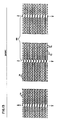
- FIGURE 9 is a top view of the grid segments shown in Figure 5 connected to adjacent grid segments in a "Z-fold" fashion to form a "Z-fold";
- FIGURE 10 is a side view showing a detail of meshing finger portions of connected grid segments shown in Figure 5;
- FIGURE 11 is a top view of a detail of the meshing finger portions of four grid segments in a hinged connection to the adjacent hinged connection by a U-bolt;
- FIGURE 12 is a view of the U-bolt used in connecting the Z-fold bundles as shown in Figure 11;
- FIGURE 13 is a top view of the Z-fold bundles connected to adjacent Z-fold bundles in a closely folded position;
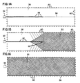
- FIGURE 14 shows a method of deploying the grid system shown in Figure 1, wherein the Z-fold bundles are towed across the water surface;
- FIGURE 15 shows the grid system being deployed wherein a portion of the grid structure is deployed;
- FIGURE 16 shows the water area of Figure 14 with the grid system substantially deployed;
- FIGURE 17 shows a spray pattern wherein sprayers are mounted on the grid structure;
- FIGURE 18 shows a sprayer pattern wherein sprayers are mounted on berms;
- FIGURE 19 shows a spray pattern wherein a sprayer is mounted on a barge or harvester and sprays in a 360° pattern;
- FIGURE 20 shows a spray pattern wherein a sprayer is mounted on a barge or harvester and sprays a pattern in an arc of 180°;
- FIGURE 21 is a cross-sectional end view of a preferred embodiment of a baffle;
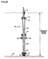
- FIGURE 22 is an end view of an alternate embodiment of a baffle;
- FIGURE 23 is a view of the baffle shown in Figure 21, wherein the baffle is bundled before deployment;
- FIGURE 24 shows the baffle of Figure 21 deployed in a depth wherein the bottom edge is substantially fully extended;
- FIGURE 25 shows a baffle of Figure 21 in low water conditions wherein the baffle uses ballast mounted at a middle distance for extending to the bottom;
- FIGURE 26 shows a detail of the fibrous baffle material;
- FIGURE 27 shows a sprayer mounting bracket for clipping to the grid system;
- FIGURE 28 shows a front view of barge or harvester vehicle; and
- FIGURE 29 shows a side view of the vehicle of Figure 28.
- A containment system used in wastewater treatment systems in conjunction with floating aquatic plants is shown generally at 31 in Figure 1. A winding
channel 36 is formed by dividingwalls 34 constructed out of earth or other suitable materials, for directing water along a winding flow path. Water enters at aninlet 38, flows through theserpentine channel 36 and is treated before leaving atexit 40. Thechannel 36 winds back and forth along a substantially rectangular area so that the distance travelled by the water in a small area is increased. Thechannel 36 is constructed so that the water flows very slowly, thereby increasing treatment time. The flow is in the transition between the laminar and turbulent regimes. This induces good mixing in the water column for maximum contact of the pollutants with the floating aquatic plants. The presence of a dense mat of floating aquatic plants and a floating grid creates a quiescent water surface so that no riprapping is required, decreasing construction costs. - The turns have curvilinear outside shapes to prevent stagnation zones in the
channels 36. Midstream curvilinear guides 44 may also be included to aid in flow direction of the water and eliminating water stagnation zones. - The system includes a
grid structure 32 floating on the water's surface for containing floating aquatic plants. The floating plants in thegrid structure 32 create an environment that eliminates harmful waste from the water as explained hereinafter. The system further includesporous baffles 46 extending transversely of the wastewater flow for controlling water flow and providing sites for flora such as bacteria to aid in water treatment. Thechannel 36 is preferably constructed so that launch ramps 55 are provided for placing a harvester or watering craft onto thechannel 36. - As shown in Figure 2, the
channel 36 is constructed so that the water surface remains as calm as possible so the floating plants are evenly distributed. To achieve this condition, the straight portions of thechannel 36 are constructed in a direction perpendicular to the prevailing direction of the wind as shown by arrow A. Furthermore, in the case where the dividingwalls 34 are earthen berms,trees 56 andshrubbery 58 may be planted along the periphery of the treatment system and along the downwind side ofberms 34 to decrease the wind velocity. Preferably theberms 34 havesprayers 62 and thetrees 56 near the water's edge so that vehicles may be driven along the top of theberms 34. - Other economies can be achieved by construction methods wherein the material removed from the
channel 36 is equal to the material added to theberms 34 andbiomass harvest areas 54 near the turns. As shown in Figure 3, the normal level of the ground before construction, as indicated by the dashed line, is such that the material added above the line to theberms 34 and thebiomass harvest areas 54 surrounding the channel is equal to that removed below the dashed line from thechannel 36. A major problem in creating most water treatment impoundments is the need for removal of material from the site or the addition of material for special berm construction. With theserpentine channel 36 and the floatinggrid system 32 of the present invention, special riprapping materials are not required and do not need to be hauled to the site. The lower grade construction materials used results in greater economies than has been possible with prior water treatment impoundments. - Preferably the channel is constructed so that the water flow is characterized by a Reynolds number between 2,000 and 5,000, and therefore in the transition between laminar and turbulent flow. The Reynolds number, R, is defined by the formula:


- As can be further shown in Figure 3, the
berms 34 may include a sprayer system including thesprayer 62 mounted on theberms 34. In this manner, the conditions can be controlled for better growth of the floating aquatic plants for removal of pollutants from the water. The special pattern of theserpentine channels 36 with parallel straight sections provides for complete spraying coverage of the water's surface by placing thesprayers 62 on theberms 34. The straight sections also provide for substantially complete coverage of the water's surface with thecontainment grids 32 as shown in Figure 1 without special shapes being required to cover the water's surface. The straight sections provide for easier deployment of thecontainment grid 32. Preferably the straight portions of thechannel 36 are constructed such that the length to width ratio is no greater than 10:1 and no less than 3:1. - As further shown in Figure 1, the water treatment system further provides construction economies by providing for modular construction and/or operation.
Hydraulic control structures control structures berms 34. During a second phase of construction an additional portion is constructed up to thecontrol structure 52. This allows use of the further portion of thechannel 36. And finally, a third portion of thechannel 36 may be constructed and fully utilized. The use ofcontrol structures alternative inlets 51 andalternative outlets 53 allows any portion of the system to be used independently of the other portions. In the system shown in Figure 1, there are twoalternative inlets 51 and twoalternative outlets 53 for 3 modules. Thealternative inlets 51 andoutlets 53 can also be a pipe or passage under theberm 34 with control valves or gates similar tocontrol structures - The
biomass harvest areas 54 located at the ends of the straight channels near the turns, provide areas for storing harvested aquatic plants from the treatment system. The harvested plants may be placed in thebiomass harvest areas 54 and dried before removal for other uses. The biomass can also be spread thin on theharvest areas 54 as a soil amendment, therefore eliminating the need to transport if off-site. - In systems using floating aquatic plants in wastewater treatment, the floating plants should be maintained so that a substantial portion of the water's surface is covered and to maximize the surface contact between the plants and the water for better growth and reproduction. Furthermore, it is preferred that the plants can be harvested from time to time so that the correct coverage of plants is maintained for efficient wastewater treatment. If the plants are left free to float, wind blows the plants to one edge of the water's surface and the coverage is not evenly distributed for improved treatment conditions. Therefore the
grid system 32 of the invention is implemented to contain the floating plants and provide a substantially even distribution upon the water's surface. As shown in Figure 1, thegrid system 32 covers a large portion of thechannel 36 along the straight portions and may be deployed to cover the turns, or a portion thereof. As shown in Figure 8, a typical plant may be theLemna plant 72, commonly referred to as duckweed, which floats on the surface of the water and is readily adaptable to a variety of conditions. TheLemna plant 72 is also efficient in treating pollutants in the water and has characteristics that make it feasible for harvesting as a cash crop. - As shown in Figure 4,
individual grid segments 70 which make up thegrid structure 32 are connected to preferably form a substantially square containment zone 68. The containment zone 68 eliminates wave action to provide for even distribution of the Lemna plants 72. - In the preferred embodiment, the portion of the
grid structure 32 which will be above the water surface will be such that it exceeds the maximum achievable wave height which is described by the formula:

Fetch is the linear measure of space that the wind may blow over to create waves. - The
grid segments 70 as shown in Figure 5 includeflotation chambers 76 which provide buoyancy such that thegrid structure 32 floats in the water at a depth such that the plants are contained by thegrid segments 70 under maximum fetch. In a preferred embodiment, theflotation chambers 76 are distributed symmetrically along a longitudinal axis of thegrid segment 70. In a preferred embodiment, the shape of theflotation chambers 76 has a substantially V-shaped cross-section below the waterline for increased stability as shown in Figure 6, however, it can be appreciated that any number of shapes may be used wherein thegrid segments 70 may be folded. Thegrid segment 70 includes meshingend finger portions 78 as shown in Figures 7 and 10. Thefinger portions 78 interlock withadjacent finger portions 78 of anothergrid segment 70. For connection, a hollow connectingtube 80 is placed through the meshingfinger portions 78 of theadjacent grid segments 70 so that thesegments 70 are connected as shown in Figure 9. Threegrid segments 70 are connected in this fashion as shown in Figure 9 to form a Z-fold 84. - A number of
grid segments 70 may be connected to form aZ-fold bundle 88 as shown in Figure 13. The length of thegrid segments 70 as compared to the width is very great, for example in aZ-fold bundle 88, an average width of a foldedsegment 70 is 4 cm, while a typical length may be 3 meters. The Z-fold bundles 88 are then connected at the hinge throughtube 80 to adjacent Z-fold bundles 88 by means of a U-bolt 82 as shown in Figure 12. The U-bolt is inserted into the hollow connectingtubes 80 as shown in Figure 11 to form connections at the hinges between the adjacent Z-fold bundles 88. In this manner adjacent Z-fold bundles 88 are connected as shown in Figure 13. Theflotation chambers 76 are spaced such that whenadjacent grid segments 70 are connected and folded back upon one another, theflotation chambers 76 do not contact theflotation chambers 76 on theadjacent grid segment 70, as shown in Figure 9. In this manner, the Z-fold bundles 88 are stored and transported in a much smaller space. For convenience and safety, the Z-fold bundles 88 are strapped together in a tight bundle during storage and shipping. - When the Z-fold bundles 88 have been connected with the U-bolts 82 as shown in Figure 13, the connections allow the Z-fold bundles 88 to be stretched out toward shore as shown by the arrows, to form containment zones 68 as shown in Figure 4. The
grid segments 70 are reversible so that replacement of damagedsegments 70 is easily accomplished by interchanging anotheridentical grid segment 70. It can also be appreciated that should an exposed portion of thegrid segment 70 become damaged, it is possible for thegrid segment 70 to be flipped over, thereby avoiding replacement. - The unique connections and assembly of the
grid structure 32 allows easy deployment as shown in Figures 14-16. As shown in Figure 14, the Z-fold bundles 88 are taken directly off a truck ortrailer 92 parked on shore. The Z-fold bundles 88 are preferably preassembled and are then attached to the adjacent Z-fold bundles 88 and connected to acable 90. As the Z-fold bundles 88 are towed across the length of the body of water, as shown in Figure 15, the Z-fold bundles 88 are gradually unstrapped and stretched out across the width of the body of water to a deployed position. When fully stretched out, the ends of thegrid 32 are attached to the shore at previously installed anchors 60. The process is continued down the length of the body of water until thegrid 32 is fully deployed as shown in Figure 16. - It can be appreciated that this method of deployment provides an easy method of assembling the
grid structure 32 and provides for substantial preassembly of the Z-fold bundles 88. The unique structure of the Z-fold bundles 88 allows them to be folded so that a small space is occupied and thebundles 88 may be transported at a lower cost. The method provides for deploying thesegments 70 over the entire length of the water, while avoiding difficult on-water construction. - In conjunction with a floating aquatic plant wastewater treatment system, sprayers are used for improved control of growth conditions. A spray system helps to control temperatures and keeps the plants clean of dust and debris. Fertilizers may be injected into the sprayed water so that the floating aquatic plants have sufficient nutrients for growth. An advantage in spraying is achieved as nutrients are applied only at the water's surface where they are needed, instead of diluting with the flow of the water.
- The sprayers are mounted in a variety of configurations so that the water surface is covered with the spray pattern; for
example sprayers 62 are mounted on theberms 34 as shown in Figure 3. Astandard sprayer 62 provides a spray pattern such as that shown in Figure 18. The configuration of theberms 34 provides access to the majority of the surface area ofwater channel 36 so that additional sprayers are not required. - Alternatively the
sprayers 62 are mounted onbrackets 124, shown in Figure 27, and mounted directly to thegrid system 32 to form a spray pattern as shown in Figure 17. Thebrackets 124 are clipped directly to the floatinggrid 32 at theU-bolt connection 82 and may be fed by a pump on shore. - In another method of spraying, the
sprayers 62 may be mounted on awatercraft 126, such as a barge or harvester, as shown in Figures 28 and 29. Thesprayer 62 may have a 360° spray pattern as shown in Figure 19, the spray pattern may spray over an angle of 180° as shown in Figure 20. In this manner, the entire surface is sprayed as thewatercraft 126 moves along thechannel 36. Thewatercraft 126 may intake water through aninlet 128, as shown in Figure 29, as long as there is aproper screening 130 to prevent intake of unwanted debris. As shown in Figure 28, thewatercraft 126 includesfins 132 to direct the Lemna plants 72 away from theinlet 128. - Other spray patterns are possible wherein a combination of berm mounted, grid mounted, and watercraft mounted sprayers are combined. For example, sprayers may be used to clean the plant's surface and control temperatures with a grid mounted sprayer system and nutrients may be intermittently added when required through a watercraft mounted system.
- As shown in Figure 3, a
porous baffle 46 is deployed which extends substantially across the width of thechannel 36 and is attached by acable 66 toanchors 60 on theberms 34. Theporous baffle 46 includes atop float 102 extending substantially along the top edge of thebaffle 46. Sheets ofporous material 104 are supported by thetop float 102 and extend substantially to the bottom of thechannel 36. As shown in Figure 21, theporous baffle 46 preferably includes aweighted chain 110 at the bottom of thebaffle 46 for insuring that theporous baffle sheets 104 extend fully to the bottom of thechannel 36. Theporous baffle 46 preferably uses a number of sheets ofporous material 104 so that flowing water is more evenly distributed across the entire channel to force an intimate contact with the entire surface of thebaffle fibers 122 as shown in Figure 26. Two or more sheets ofbaffle material 104 can be connected at an intermediate portion byrivets 106 as shown in Figure 21. - As shown in Figure 26, the
material 104 is a loosely packed fibrous material. Thefibers 122 provide a large surface area so that flora and other organisms may attach to thefibers 122 and have a greater chance of contacting the pollutants in the water. In a preferred embodiment theporous material 104 provides a surface area at least seven times the surface area of the square section of thematerial 104. - In an alternative embodiment shown in Figure 22, a
top float 112 similar to agrid segment 70 is used instead of thefloat 102 shown in Figure 21. The alternate embodiment further includesbolts 114 and reinforcingplates 116 for connecting adjacent portions of theporous baffle sheets 104. -
Baffle sections 46 are tied in bundles as shown in Figure 23. When deployed, thebaffles 46 are untied and thebottom ballast 110 drops thebaffle 46 to the bottom of thechannel 36. - As shown in Figure 24, when fully deployed, the
baffle 46 further includes aballast 120 at an intermediate position between thetop float 102 and thebottom chain 110. Themiddle ballast 120 serves to keep the porous baffle vertical at low water levels, as shown in Figure 25. - The porous baffles 46 are installed in conditions that are predominantly anaerobic, induced by the mat of floating
aquatic plants 72 and thegrid 32. This prevents thick aerobic slimes from building up on theporous baffles 46 and maintains the open structure to allow intimate contact of the wastewater with the thin anaerobic microbial slime on thefibers 122. In most ponds, the majority of the organisms which treat the water are at the bottom of the pond so that very little of the water comes into contact with the microorganisms. With theporous baffle 46, the water flows through the sheets ofbaffle material 104 and greatly improves the opportunity for contact with the microorganisms, yet prevents clogging resulting from heavy slime buildup. As shown in Figure 26, thebaffle fibers 122 allow free flow through theporous baffle 46 and provide a large surface area for the microorganisms to colonize.
Claims (7)
- A reversible floating grid segment (70) comprising:
a barrier portion;
connecting portions (78), extending from the ends of the grid segment, the connecting portions (78) extending at an angle of greater than O degrees from the longitudinal axis of the barrier portion, the connecting portions including finger portions (78) having apertures therethrough such that the finger portions mesh with finger portions (78) of an adjacent grid segment (70) such that the apertures are aligned with one another, wherein the grid segments may be connected by inserting connecting means (80) into the apertures of the finger portions (78) of adjacent grid segments (70); and
flotation chambers (76) spaced along the barrier portion of the grid segment (70) wherein the chambers (76) are spaced so that the flotation chambers (76) do not contact flotation chambers (76) of an adjacent connected grid segment (70) when the grid segment (70) is connected to the adjacent grid segment (70) and when the segments are folded about the connected finger portions (78). - A floating plant containment system comprising reversible floating barriers (70) having flotation means (76) for giving buoyancy to the barriers and meshing end portions (78); the meshing end portions (78) connected by a hollow connecting tube (80) inserted into aligned apertures of the meshing end portions (78) of adjacent barriers (70), to form a Z-fold bundle (88), the Z-fold bundle (88) being connected to adjacent Z-fold bundles (88) by U-bolts (82) inserted into the connecting tubes (80), so that the barriers (70) form a substantially square containment zone.
- A floating aquatic plant containment system comprising floating barrier segments (70) connected in a floating grid structure (32), wherein the barrier segments have flotation means (76) for giving buoyancy to the barrier segments (70) and end portions (78), wherein the end portions have meshing fingers having apertures therethrough, and wherein the barrier segments (70) are connected to an adjacent barrier segment (70) by a hollow connecting tube (80) inserted through the apertures in the meshing fingers (78) to form a Z-fold bundle (88), and wherein the Z-fold bundles (88) are connected to adjacent Z-fold bundles (88) by U-bolts (82) inserted through the hollow connecting tubes (80) of the Z-fold bundle (88) and the adjacent Z-fold bundles (88) so that a grid structure (32) is created by unfolding the connected Z-fold bundles (88).
- A buoyant containing grid section for an aquatic biomass containment grid structure, comprising:
an extended generally linear member (70) having two ends and having flotation means (76) for giving buoyancy to the linear member, the flotation means (76) comprising flotation chambers (76) within the linear member (70) located between the two ends (78) of the linear member, the linear member (70) having a hinge section (78) at each of the two ends, the hinge section each having protruding hinge knuckles (78) whereby a plurality of grid segments (70) may be pin connected through apertures in the protruding hinge knuckles (78) of the hinge section and compactly folded to lie against one another. - A floating aquatic biomass containment barrier cell (32) comprising:
at least three grid segments (70), as defined in Claim 4, the protruding hinge knuckles (78) having portions defining an aperture, wherein the grid segments (70) are joined end-to-end by interconnected hinge knuckles (78) of adjoining segments (70) and wherein hinge hollow tubes (80) are inserted through three aligned hinged knuckles (78) to connect the segments (70) to form a closed cell (32) and wherein the hinge sections allow the grid segments (70), when not connected to form a closed cell, to be folded to lie against one another, generally parallel to one another. - A network of floating aquatic biomass containment barriers, comprising:
a plurality of containment grid segments (70), as defined in Claim 4 or 5 and wherein the segments are joined to form a network of cells to restrain a floating aquatic biomass. - A method of deploying a floating point containment system at a deployment site comprising the steps of: attaching a floating barrier segment (70) to adjacent barrier segments (70) by inserting a hollow connecting tube (80) through a hole at meshing ends of the barrier segments to form a Z-fold bundle (88);
transporting the Z-fold bundles (88) to the deployment site;
attaching adjacent Z-fold bundles (88) by inserting a U-bolt (82) through the hollow connecting tubes (80) of the Z-fold bundles (88) and the adjacent Z-fold bundles (88);
towing the attached Z-fold bundles (88) onto the water surface;
stretching the attached Z-fold bundles (88) laterally from the towing direction to cover the water surface; adding Z-fold bundles (88) until a sufficient number are attached to form a deployed grid (32) which covers the water surface; and
securing the deployed grid (32) to shore.
Applications Claiming Priority (3)
| Application Number | Priority Date | Filing Date | Title |
|---|---|---|---|
| US07/323,022 US5096577A (en) | 1989-03-17 | 1989-03-17 | Floating aquatic plant water treatment system |
| US323022 | 1989-03-17 | ||
| PCT/US1990/001212 WO1990011255A1 (en) | 1989-03-17 | 1990-03-06 | Floating aquatic plant water treatment system |
Publications (2)
| Publication Number | Publication Date |
|---|---|
| EP0463057A1 EP0463057A1 (en) | 1992-01-02 |
| EP0463057B1 true EP0463057B1 (en) | 1995-04-26 |
Family
ID=23257460
Family Applications (1)
| Application Number | Title | Priority Date | Filing Date |
|---|---|---|---|
| EP90905008A Expired - Lifetime EP0463057B1 (en) | 1989-03-17 | 1990-03-06 | Floating aquatic plant water treatment system |
Country Status (12)
| Country | Link |
|---|---|
| US (3) | US5096577A (en) |
| EP (1) | EP0463057B1 (en) |
| AT (1) | ATE121709T1 (en) |
| AU (5) | AU632017B2 (en) |
| BG (1) | BG95111A (en) |
| BR (1) | BR9007226A (en) |
| DE (1) | DE69018983T2 (en) |
| ES (1) | ES2074159T3 (en) |
| HU (1) | HUT75208A (en) |
| IL (1) | IL93699A (en) |
| MX (1) | MX174352B (en) |
| WO (1) | WO1990011255A1 (en) |
Families Citing this family (35)
| Publication number | Priority date | Publication date | Assignee | Title |
|---|---|---|---|---|
| JPH07508451A (en) * | 1991-09-20 | 1995-09-21 | スペース バイオスフェアーズ ベンチャー | wastewater treatment equipment |
| WO1994006720A1 (en) * | 1992-09-16 | 1994-03-31 | The Lemna Corporation | Floating nitrification reactor in a treatment pond |
| ES2126657T3 (en) * | 1992-10-07 | 1999-04-01 | Ozkorp Pty Limited | SYSTEM FOR THE TREATMENT OF RESIDUAL WATERS WITH ODOR CONTROL. |
| US6033559A (en) * | 1993-03-31 | 2000-03-07 | Microbial Aquatic Treatment | Compositions and methods of use of constructed microbial mats |
| US6008028A (en) * | 1993-03-31 | 1999-12-28 | Microbial And Aquatic Treatment Systems | Compositions of constructed microbial mats |
| US5614097A (en) * | 1993-03-31 | 1997-03-25 | Microbial And Aquatic Treatment Systems, Inc. | Compositions and method of use of constructed microbial mats |
| DK0691938T3 (en) * | 1993-03-31 | 1998-03-23 | Microbial & Aquatic Treatment | Silage microbial mat system and method |
| US5593575A (en) * | 1994-04-14 | 1997-01-14 | Cretini; Gus R. | Floating cover and baffle system |
| US5528856A (en) * | 1995-02-15 | 1996-06-25 | Landmark Reclamation, Inc. | Biomass impoundment management system for purifying water |
| US5736047A (en) * | 1995-02-28 | 1998-04-07 | Lemna Corporation | Hybrid biological nutrient removal system |
| US5736048A (en) * | 1995-05-24 | 1998-04-07 | Spelman College | Biological process of remediating chemical contamination of a pond |
| DE19648646A1 (en) * | 1996-11-18 | 1998-06-25 | Bioaqua Umwelttechnik Gmbh Oek | Waste water treated by fermentive coagulation and bio-reactor system |
| ES2120388B1 (en) * | 1997-04-04 | 1999-03-01 | Univ Madrid Politecnica | PROCEDURE FOR THE TREATMENT OF WASTEWATER AND POLLUTANT DISCHARGES BASED ON CROPS OF EMERGING MACROPHYTES CONVERTED INTO FLOATS. |
| US5861095A (en) * | 1997-04-09 | 1999-01-19 | Lemna Corporation | Method and device for treating wastewater |
| US5836108A (en) * | 1997-04-28 | 1998-11-17 | Scheuer; David W. | Floating planter box |
| RU2142919C1 (en) * | 1999-03-01 | 1999-12-20 | Общество с ограниченной ответственностью Научно-производственное объединение "Эколандшафт" | Method of cleaning natural and waste water and device "floating bank" for realization of this method |
| RU2157794C1 (en) * | 1999-05-07 | 2000-10-20 | Серпокрылов Николай Сергеевич | Device for tertiary treatment of sewage |
| US6851891B2 (en) | 2000-02-03 | 2005-02-08 | Baumgartner Environics, Inc. | Organic slurry storage basin cover |
| US6659688B2 (en) | 2000-02-03 | 2003-12-09 | Baumgartner Environics, Inc. | Organic slurry basin storage cover and method of fabricating and deploying cover |
| US6673241B1 (en) | 2000-05-03 | 2004-01-06 | Monsanto Company | Self-floating cover system for a body of water |
| US6773595B2 (en) | 2001-03-29 | 2004-08-10 | Charles J. Gantzer | Compartmentalized facultative lagoon and method of creating and maintaining such a lagoon |
| WO2002088474A2 (en) * | 2001-04-26 | 2002-11-07 | Gunderboom, Inc. | Y-panel anchoring system for boom installation |
| US20070217867A1 (en) * | 2006-03-15 | 2007-09-20 | Son Rae S | Floating barriers for retaining substances in confined area, and barrier systems usable for treating oil spill in the water and for other applications |
| US7632407B1 (en) | 2006-08-07 | 2009-12-15 | Debusk Thomas A | Rapid proliferation of aquatic plant growth facilitation system and associated methods |
| US7575058B2 (en) | 2007-07-10 | 2009-08-18 | Baker Hughes Incorporated | Incremental annular choke |
| MX2010012591A (en) * | 2008-05-23 | 2011-04-11 | Macrofitas S L | Floating cell and island with a floating macrophyte filter. |
| ES2331556B2 (en) * | 2009-04-29 | 2010-10-14 | Universidad Politecnica De Madrid | PLANTATION UNIT FOR THE CROP OF HELOPHIT PLANTS AND PLANTATION SYSTEM THAT INCLUDES THE SAME. |
| RU2421270C1 (en) * | 2009-10-05 | 2011-06-20 | Общество с ограниченной ответственностью "Аквафор" | Filtered water unit for water treatment system, water treatment system storage unit (versions), and water treatment system (versions) |
| CA2686250C (en) * | 2009-11-12 | 2016-10-11 | Fountainhead, Llc | Floating treatment streambed |
| US8920071B2 (en) * | 2011-09-07 | 2014-12-30 | Hazard Mitigation, Inc. | Apparatus and method for limiting ice formation |
| US8889006B2 (en) | 2013-01-21 | 2014-11-18 | Leon A. Lassovsky | System for wastewater treatment using aquatic plants |
| WO2014113768A1 (en) * | 2013-01-21 | 2014-07-24 | Lassovsky Leon A | System for wastewater treatment using aquatic plants |
| RU2555896C1 (en) * | 2014-02-20 | 2015-07-10 | Общество С Ограниченной Ответственностью "Эковолга" | Device for cleaning water reservoirs from blue-green algae |
| US20220274856A1 (en) * | 2019-07-31 | 2022-09-01 | Arizona Board Of Regents On Behalf Of The University Of Arizona | Phyto-mediated wastewater treatment bioreactor (pwbr) |
| US12593764B2 (en) | 2023-07-21 | 2026-04-07 | Rutgers, The State University Of New Jersey | Automated growth system for floating aquatic plants and method |
Family Cites Families (35)
| Publication number | Priority date | Publication date | Assignee | Title |
|---|---|---|---|---|
| DE277905C (en) * | ||||
| US2283472A (en) * | 1939-10-25 | 1942-05-19 | Blaine M Tuxhorn | Apparatus for establishing fish habitats |
| US3155609A (en) * | 1960-05-09 | 1964-11-03 | Pampel Leonard Fredrick | Stabilization of a closed or open water system through the selective utilization of light |
| AT241896B (en) * | 1964-01-22 | 1965-08-10 | Heinrich Sterlich | Hydroponic culture method for growing floating plants or seeds and device for carrying out the method |
| US3385786A (en) * | 1966-10-28 | 1968-05-28 | Interior Usa | System for biological treatment of sewage |
| US3456385A (en) * | 1966-11-18 | 1969-07-22 | Charles F Plath | Plant cutting supports |
| US3653192A (en) * | 1970-12-14 | 1972-04-04 | Bryant Charles B | Method and apparatus for harvesting aquatic vegetation |
| US3839198A (en) * | 1971-01-25 | 1974-10-01 | G Shelef | Process for sewage treatment and wastewater reclamation |
| US3760946A (en) * | 1971-03-31 | 1973-09-25 | Cherne Ind Inc | Combination sewage treatment and cooling system |
| US3911514A (en) * | 1971-06-05 | 1975-10-14 | Sumitomo Bakelite Co | Raft materials for aquatic cultivation |
| GB1373035A (en) * | 1972-02-22 | 1974-11-06 | Hemberg E F C | Method of and means for breaking or dissipating the force of waves |
| FR2239120A5 (en) * | 1973-07-27 | 1975-02-21 | Reconquete Milieux Naturels | Fixtures for marine plant cuttings - are concrete rings with handling loops and upper slots |
| US3852378A (en) * | 1973-10-03 | 1974-12-03 | R Guida | Water-purifying attachment for boats |
| US3959923A (en) * | 1974-12-04 | 1976-06-01 | Erno Raumfahrttechnik Gmbh | Equipment for growing algae |
| US3927491A (en) * | 1974-12-30 | 1975-12-23 | Robert S Farnsworth | Process and apparatus for growing plants |
| FR2361060A1 (en) * | 1976-08-13 | 1978-03-10 | British Petroleum Co | Industrial cultivation of photosynthetic material by solar irradiation - with heat trap screens to supply electricity from surplus solar energy |
| HU174397B (en) * | 1977-08-04 | 1979-12-28 | Varosepitesi Tudomanyos | Process for refining waters poured into the receptive water and containing materials causing the latter's eutrphysation, and apparatus for this process |
| US4209943A (en) * | 1977-09-02 | 1980-07-01 | Hunt James P | Process and apparatus for commercial farming of marine and freshwater hydrophytes |
| US4169050A (en) * | 1977-11-03 | 1979-09-25 | Solar Aquasystems, Inc. | Buoyant contact surfaces in waste treatment pond |
| US4133141A (en) * | 1977-12-16 | 1979-01-09 | Lee Choong W | Apparatus and method for growing plants |
| US4320594A (en) * | 1978-12-28 | 1982-03-23 | Battelle Memorial Institute | Mass algal culture system |
| US4324067A (en) * | 1980-02-04 | 1982-04-13 | The University Of Arizona Foundation | Algal cell harvesting |
| SU906455A1 (en) * | 1980-02-27 | 1982-02-23 | Украинский Ордена "Знак Почета" Научно-Исследовательский Институт Лесного Хозяйства И Агролесомелиорации Им.Г.Н.Высоцкого | Device for substrateless growing of water and semiwater plants |
| GB2075323B (en) * | 1980-03-25 | 1983-08-10 | Greenterior Co Ltd | Soil-less plant growing device |
| US4333827A (en) * | 1980-08-14 | 1982-06-08 | Apt Inc. | Automatic engine shut down device and systems employing the same |
| US4333263A (en) * | 1980-10-07 | 1982-06-08 | The Smithsonian Institution | Algal turf scrubber |
| JPS607956B2 (en) * | 1981-10-21 | 1985-02-28 | 東亜建設工業株式会社 | Water purification method using aquatic plants |
| US4487588A (en) * | 1982-08-10 | 1984-12-11 | Mangrove Systems, Inc. | Submersible raft for the cultivation of plant life |
| US4536988A (en) * | 1984-01-31 | 1985-08-27 | The Lemna Corporation | Aquatic biomass containment barrier and method of assembling same |
| US4806251A (en) * | 1986-09-16 | 1989-02-21 | Aeration Industries, Inc. | Oscillating propeller type aerator apparatus and method |
| US4872985A (en) * | 1986-11-10 | 1989-10-10 | Ray Dinges | Method for application of wastewater to plants for improved wastewater treatment |
| US4747958A (en) * | 1987-07-20 | 1988-05-31 | Eberhardt Thomas E | Method and apparatus for treating bodies of water |
| US4738563A (en) * | 1987-07-22 | 1988-04-19 | Clark Stephen E | Buoyant marine fence |
| DD277905A1 (en) * | 1988-12-09 | 1990-04-18 | Wasserwirtschaftsdirektion Ber | METHOD AND DEVICE FOR CLEANING EQUIPMENT AND SMALL PROPUTS |
| US5011604A (en) * | 1990-02-07 | 1991-04-30 | Wilde Edward W | Use of microalgae to remove pollutants from power plant discharges |
-
1989
- 1989-03-17 US US07/323,022 patent/US5096577A/en not_active Expired - Fee Related
-
1990
- 1990-03-06 DE DE69018983T patent/DE69018983T2/en not_active Expired - Fee Related
- 1990-03-06 HU HU902776A patent/HUT75208A/en unknown
- 1990-03-06 WO PCT/US1990/001212 patent/WO1990011255A1/en not_active Ceased
- 1990-03-06 BR BR909007226A patent/BR9007226A/en not_active Application Discontinuation
- 1990-03-06 EP EP90905008A patent/EP0463057B1/en not_active Expired - Lifetime
- 1990-03-06 AT AT90905008T patent/ATE121709T1/en not_active IP Right Cessation
- 1990-03-06 ES ES90905008T patent/ES2074159T3/en not_active Expired - Lifetime
- 1990-03-06 AU AU52878/90A patent/AU632017B2/en not_active Ceased
- 1990-03-11 IL IL9369990A patent/IL93699A/en unknown
- 1990-03-16 MX MX1993990A patent/MX174352B/en unknown
-
1991
- 1991-09-16 BG BG095111A patent/BG95111A/en unknown
-
1993
- 1993-01-13 AU AU31154/93A patent/AU657026B2/en not_active Ceased
- 1993-01-13 AU AU31153/93A patent/AU3115393A/en not_active Abandoned
- 1993-01-13 AU AU31158/93A patent/AU3115893A/en not_active Abandoned
- 1993-01-13 AU AU31157/93A patent/AU3115793A/en not_active Abandoned
- 1993-02-11 US US08/017,340 patent/US5342512A/en not_active Expired - Fee Related
- 1993-07-06 US US08/087,031 patent/US5409601A/en not_active Expired - Fee Related
Also Published As
| Publication number | Publication date |
|---|---|
| AU632017B2 (en) | 1992-12-10 |
| MX174352B (en) | 1994-05-10 |
| US5409601A (en) | 1995-04-25 |
| US5096577A (en) | 1992-03-17 |
| AU5287890A (en) | 1990-10-22 |
| ATE121709T1 (en) | 1995-05-15 |
| US5342512A (en) | 1994-08-30 |
| BG95111A (en) | 1993-12-24 |
| AU3115493A (en) | 1993-03-11 |
| IL93699A0 (en) | 1990-12-23 |
| AU3115393A (en) | 1993-03-11 |
| DE69018983T2 (en) | 1995-09-28 |
| AU3115793A (en) | 1993-03-11 |
| AU657026B2 (en) | 1995-02-23 |
| EP0463057A1 (en) | 1992-01-02 |
| IL93699A (en) | 1994-07-31 |
| BR9007226A (en) | 1991-11-26 |
| HUT75208A (en) | 1997-04-28 |
| AU3115893A (en) | 1993-03-11 |
| HU902776D0 (en) | 1992-01-28 |
| DE69018983D1 (en) | 1995-06-01 |
| WO1990011255A1 (en) | 1990-10-04 |
| ES2074159T3 (en) | 1995-09-01 |
Similar Documents
| Publication | Publication Date | Title |
|---|---|---|
| US5409601A (en) | Floating aquatic plant treatment system | |
| US4536988A (en) | Aquatic biomass containment barrier and method of assembling same | |
| US8250808B2 (en) | Super-enhanced, adjustably buoyant floating island | |
| US4169050A (en) | Buoyant contact surfaces in waste treatment pond | |
| AU743448B2 (en) | Purification system for disposal of polluted or waste water using water plants | |
| EP0952121B1 (en) | Process for purification of waste waters and contaminant spills based on the use of cultivated emergent macrophytes converted into floating cultures | |
| US5264127A (en) | Floating aquatic plant water treatment system with sprayer system | |
| US5180501A (en) | Floating aquatic plant water treatment system | |
| JP2002102884A (en) | Unit type wastewater treatment apparatus employing ecological system and wastewater treatment method using the same | |
| CA2879781C (en) | Floating treatment bed for plants | |
| CN104803557A (en) | Compound type ditch pond wetland system with functions of farmland drainage purification and ecological restoration | |
| KR20030065039A (en) | Emerged plant vegetation floater and purification the water quality using the floater | |
| DE69918110T2 (en) | BIOLOGICAL TREATMENT OF WATER FOR DRINKING WATER TREATMENT | |
| CN204529619U (en) | The ditch pool wet land system of composite type purifying farmland drainage and restoration of the ecosystem | |
| JP2001321158A (en) | Method for producing filamentous diatoms | |
| KR101065372B1 (en) | Biotope floating on water | |
| KR100356327B1 (en) | Raft-Type Artificial Plant Island | |
| KR100281524B1 (en) | The hydroponics structure using waste tires and hydroponic agriculture and water purification method with that | |
| KR200293165Y1 (en) | Float box for planting water plant for water purifying | |
| Driebergen | Environmental development in two of the border-lakes of the IJsselmeerpolders in the Netherlands | |
| WO2023225737A1 (en) | Septic tank for treating wastewater | |
| EP0035611A1 (en) | Process and apparatus for commercial farming of marine and freshwater macrophytes | |
| JP2002143836A (en) | Device and method for purifying water in rice field or the like and countermeasure against flood by using rice field or the like | |
| Leffler | CONSTRUCTED WETLANDS FOR WASTEWATER TREATMENT AND EDUCATION |
Legal Events
| Date | Code | Title | Description |
|---|---|---|---|
| PUAI | Public reference made under article 153(3) epc to a published international application that has entered the european phase |
Free format text: ORIGINAL CODE: 0009012 |
|
| 17P | Request for examination filed |
Effective date: 19910911 |
|
| AK | Designated contracting states |
Kind code of ref document: A1 Designated state(s): AT BE DE DK ES FR GB IT NL SE |
|
| 17Q | First examination report despatched |
Effective date: 19920812 |
|
| GRAA | (expected) grant |
Free format text: ORIGINAL CODE: 0009210 |
|
| AK | Designated contracting states |
Kind code of ref document: B1 Designated state(s): AT BE DE DK ES FR GB IT NL SE |
|
| PG25 | Lapsed in a contracting state [announced via postgrant information from national office to epo] |
Ref country code: DK Effective date: 19950426 Ref country code: AT Effective date: 19950426 |
|
| REF | Corresponds to: |
Ref document number: 121709 Country of ref document: AT Date of ref document: 19950515 Kind code of ref document: T |
|
| ET | Fr: translation filed | ||
| REF | Corresponds to: |
Ref document number: 69018983 Country of ref document: DE Date of ref document: 19950601 |
|
| ITF | It: translation for a ep patent filed | ||
| REG | Reference to a national code |
Ref country code: ES Ref legal event code: FG2A Ref document number: 2074159 Country of ref document: ES Kind code of ref document: T3 |
|
| PGFP | Annual fee paid to national office [announced via postgrant information from national office to epo] |
Ref country code: GB Payment date: 19960228 Year of fee payment: 7 |
|
| PLBE | No opposition filed within time limit |
Free format text: ORIGINAL CODE: 0009261 |
|
| STAA | Information on the status of an ep patent application or granted ep patent |
Free format text: STATUS: NO OPPOSITION FILED WITHIN TIME LIMIT |
|
| 26N | No opposition filed | ||
| PGFP | Annual fee paid to national office [announced via postgrant information from national office to epo] |
Ref country code: SE Payment date: 19970213 Year of fee payment: 8 Ref country code: FR Payment date: 19970213 Year of fee payment: 8 |
|
| PGFP | Annual fee paid to national office [announced via postgrant information from national office to epo] |
Ref country code: NL Payment date: 19970218 Year of fee payment: 8 |
|
| PGFP | Annual fee paid to national office [announced via postgrant information from national office to epo] |
Ref country code: DE Payment date: 19970225 Year of fee payment: 8 |
|
| PG25 | Lapsed in a contracting state [announced via postgrant information from national office to epo] |
Ref country code: GB Effective date: 19970306 |
|
| PGFP | Annual fee paid to national office [announced via postgrant information from national office to epo] |
Ref country code: ES Payment date: 19970317 Year of fee payment: 8 Ref country code: BE Payment date: 19970317 Year of fee payment: 8 |
|
| GBPC | Gb: european patent ceased through non-payment of renewal fee |
Effective date: 19970306 |
|
| PG25 | Lapsed in a contracting state [announced via postgrant information from national office to epo] |
Ref country code: SE Free format text: LAPSE BECAUSE OF NON-PAYMENT OF DUE FEES Effective date: 19980307 Ref country code: ES Free format text: LAPSE BECAUSE OF NON-PAYMENT OF DUE FEES Effective date: 19980307 |
|
| PG25 | Lapsed in a contracting state [announced via postgrant information from national office to epo] |
Ref country code: FR Free format text: THE PATENT HAS BEEN ANNULLED BY A DECISION OF A NATIONAL AUTHORITY Effective date: 19980331 Ref country code: BE Free format text: LAPSE BECAUSE OF NON-PAYMENT OF DUE FEES Effective date: 19980331 |
|
| BERE | Be: lapsed |
Owner name: THE LEMNA CORP. Effective date: 19980331 |
|
| PG25 | Lapsed in a contracting state [announced via postgrant information from national office to epo] |
Ref country code: NL Free format text: LAPSE BECAUSE OF NON-PAYMENT OF DUE FEES Effective date: 19981001 |
|
| NLV4 | Nl: lapsed or anulled due to non-payment of the annual fee |
Effective date: 19981001 |
|
| PG25 | Lapsed in a contracting state [announced via postgrant information from national office to epo] |
Ref country code: DE Free format text: LAPSE BECAUSE OF NON-PAYMENT OF DUE FEES Effective date: 19981201 |
|
| EUG | Se: european patent has lapsed |
Ref document number: 90905008.0 |
|
| REG | Reference to a national code |
Ref country code: FR Ref legal event code: ST |
|
| REG | Reference to a national code |
Ref country code: ES Ref legal event code: FD2A Effective date: 20000403 |
|
| PG25 | Lapsed in a contracting state [announced via postgrant information from national office to epo] |
Ref country code: IT Free format text: LAPSE BECAUSE OF NON-PAYMENT OF DUE FEES;WARNING: LAPSES OF ITALIAN PATENTS WITH EFFECTIVE DATE BEFORE 2007 MAY HAVE OCCURRED AT ANY TIME BEFORE 2007. THE CORRECT EFFECTIVE DATE MAY BE DIFFERENT FROM THE ONE RECORDED. Effective date: 20050306 |