EP0462580B1 - Optischer Faserkreisel mit Selbstdiagnosefunktion - Google Patents
Optischer Faserkreisel mit Selbstdiagnosefunktion Download PDFInfo
- Publication number
- EP0462580B1 EP0462580B1 EP91109997A EP91109997A EP0462580B1 EP 0462580 B1 EP0462580 B1 EP 0462580B1 EP 91109997 A EP91109997 A EP 91109997A EP 91109997 A EP91109997 A EP 91109997A EP 0462580 B1 EP0462580 B1 EP 0462580B1
- Authority
- EP
- European Patent Office
- Prior art keywords
- signal
- diagnostic
- fiber optic
- optic gyro
- light beam
- Prior art date
- Legal status (The legal status is an assumption and is not a legal conclusion. Google has not performed a legal analysis and makes no representation as to the accuracy of the status listed.)
- Expired - Lifetime
Links
Images




Classifications
-
- G—PHYSICS
- G01—MEASURING; TESTING
- G01C—MEASURING DISTANCES, LEVELS OR BEARINGS; SURVEYING; NAVIGATION; GYROSCOPIC INSTRUMENTS; PHOTOGRAMMETRY OR VIDEOGRAMMETRY
- G01C19/00—Gyroscopes; Turn-sensitive devices using vibrating masses; Turn-sensitive devices without moving masses; Measuring angular rate using gyroscopic effects
- G01C19/58—Turn-sensitive devices without moving masses
- G01C19/64—Gyrometers using the Sagnac effect, i.e. rotation-induced shifts between counter-rotating electromagnetic beams
- G01C19/72—Gyrometers using the Sagnac effect, i.e. rotation-induced shifts between counter-rotating electromagnetic beams with counter-rotating light beams in a passive ring, e.g. fibre laser gyrometers
- G01C19/726—Phase nulling gyrometers, i.e. compensating the Sagnac phase shift in a closed loop system
-
- G—PHYSICS
- G01—MEASURING; TESTING
- G01C—MEASURING DISTANCES, LEVELS OR BEARINGS; SURVEYING; NAVIGATION; GYROSCOPIC INSTRUMENTS; PHOTOGRAMMETRY OR VIDEOGRAMMETRY
- G01C19/00—Gyroscopes; Turn-sensitive devices using vibrating masses; Turn-sensitive devices without moving masses; Measuring angular rate using gyroscopic effects
- G01C19/58—Turn-sensitive devices without moving masses
- G01C19/64—Gyrometers using the Sagnac effect, i.e. rotation-induced shifts between counter-rotating electromagnetic beams
- G01C19/72—Gyrometers using the Sagnac effect, i.e. rotation-induced shifts between counter-rotating electromagnetic beams with counter-rotating light beams in a passive ring, e.g. fibre laser gyrometers
- G01C19/721—Details, e.g. optical or electronical details
Definitions
- the present invention relates to a closed loop type fiber optic gyro and, more particularly, to a fiber optic gyro which permits a fault diagnosis to be made.
- Fig. 1 shows a conventional closed loop type fiber optic gyro.
- a light source 12 is driven by a light source driver 11 to emit light.
- the light thus emitted from the light source 11 is provided via an optical coupler 13 to an optical splitter/coupler 15 which serves as interference means in an optical integrated circuit 14, and the light is incident therefrom, as a right-handed or clockwise light and a left-handed or counterclock wise light, to both ends of an optical fiber coil 16 serving as an optical path which makes at least one loop.
- the right-handed light and the left-handed light emitted from the optical fiber coil 16 after propagation therethrough are combined by the optical splitter/coupler 15 and interfere with each other.
- the resulting interference light is provided via the optical coupler 13 to a photodetector 17 used as photoelectric conversion means for conversion into an electric signal corresponding to the intensity of the interference light.
- a bias phase modulator 18 is connected in series between the optical splitter/coupler 15 and one end of the optical fiber coil 16.
- a square-wave bias phase modulating signal from a bias phase modulator driver 19 is applied to the bias phase modulator 18 to drive it, by which the right-handed light and the left-handed light passing therethrough are both subjected to a + ⁇ /4 rad. phase shift and a - ⁇ /4 rad. phase shift alternately every propagation time ⁇ of light through the optical fiber coil 16.
- the output of the photodetector 17 is synchronously detected by a synchronous detector 21 in synchronization with the phase shift.
- phase difference ⁇ R 4 ⁇ RL ⁇ C ⁇
- R the radius of the optical fiber coil 16
- L the length of the optical fiber coil 16
- ⁇ the wavelength of the light from the light source 12
- C the velocity of light in a vacuum
- ⁇ the input angular rate
- the output of the synchronous detector 21 is also zero, but when the input angular rate ⁇ develops, the synchronous detector 21 yields a DC output corresponding to the input angular rate ⁇ .
- the DC output is integrated by an integrator 22, whose output is applied to a ramp generator (sawtooth wave generator) 23 to drive it. That is, the ramp generator 23 repeatedly generates a voltage which linearly varies to a predetermined value at a slope corresponding to the magnitude of the integrated output and is reset when it reaches the predetermined value.
- this ramp output namely, a sawtooth wave output to a feedback phase modulator 24 connected in series between the optical splitter/coupler 15 and one end of the optical fiber coil 16 and serving as phase difference generating means
- the right-handed light and the left-handed light are phase modulated in the feedback phase modulator with said sawtooth wave output to cancel the phase difference ⁇ R therebetween.
- a closed loop for effecting negative feedback control so as to reduce the phase difference between the right-handed light and the left-handed light to zero is formed.
- the ramp generator 23 When the angular rate of forward rotation is provided to the optical fiber coil 16, the ramp generator 23 generates positive-going ramp waves and applies them to an output circuit 25, which, in turn, outputs a positive pulse for each ramp wave. When the angular rate of backward rotation is provided to the optical fiber coil 16, the ramp generator 23 applies negative-going ramp waves to the output circuit 25, which outputs a negative pulse for each ramp wave.
- the conventional closed loop type fiber optic gyro described above has no self-diagnositc feature; therefore, once it is built in an apparatus, it is impossible to know whether the fiber optic gyro is normal, unless a check is made of the output of the apparatus after physically providing thereto an input angular rate or the fiber optic gyro produces an abnormal output owing to its failure.
- the document JP-A-63-128225 discloses an open loop type fiber optic gyro having a fault diagnostic function.
- an oscillator provides a bias signal for a bias phase modulation of a clockwise travelling light beam and a counterclockwise travelling light beam by means of a phase modulator.
- the bias signal is directly applied to a a first and, via a frequency doubling frequency converter, a second synchronous detector.
- the output signals from the two synchronous detectors are supplied to a signal processing section which outputs a first signal corresponding to the angular velocity of the fiber optic coil.
- the output signals from the two synchronous detectors are supplied to an adder in which their absolute values are added, and this added output is supplied to a voltage comparator serving as a fault deciding section.
- the fault deciding section decides that the gyro has a fault in case the output of the adder exceeds either an upper or a lower limit. The upper limit and the lower limit are just beyond the ends of the range of the output of the adder that is to be expected during faultless operation.
- a diagnostic signal from diagnostic signal generating means is applied by signal coupling means to a closed loop, the resulting response signal is led out therefrom and a fault diagnosis is made by diagnostic means, based on the response signal.
- Fig. 2 illustrates in block form a first embodiment of the fiber optic gyro of the present invention, in which the parts corresponding to those in Fig. 1 are identified by the same reference numerals.
- a diagnostic unit. 26 is provided, which responds to a diagnostic instruction DINS to cause a diagnostic signal generator 27 to generate a diagnostic signal DS.
- the diagnostic signal DS is applied to a combiner 28, wherein it is superimposed on the output of the synchronous detector 21, and the combined output is provided to the integrator 22.
- the output RS of the synchronous detector 21 is branched by a signal extractor 29 to the diagnostic unit 26.
- the diagnostic unit 26 is formed by a microcomputer, for example.
- Fig. 3 shows its function.
- a diagnostic signal selecting part 26b is started, from which data specifying any one of DC diagnostic signals of a plurality of predetermined levels are output in digital form in a sequential order and data specifying any one of AC diagnostic signals of a predetermined level and a plurality of frequencies are also output in digital form in a sequential order.
- the signal input from the signal extractor 29 is checked by a diagnostic decision part 26c as to whether it has a predetermined level relative to the corresponding diagnostic signal DS and as to whether its delay behind the diagnostic signal DS is within a given limit, and when the signal DS is an AC signal, in addition thereto the follow-up property of the input signal and the sameness of its waveform with respect to the signal DS are also checked. Based on the results of such checking, the diagnostic decision part 26c decides whether the operation of the fiber optic gyro is normal and outputs the result of the decision as a diagnostic result DRES via the I/O signal processing part 26a for display on a display unit (not shown).
- the diagnostic signal generator 27 is constituted by a D/A converter.
- the signal extractor 29 extracts the output RS of the synchronous detector 21 by a buffer circuit of a high input impedance so as not to affect the loop of the fiber optic gyro and converts the extracted signal by an A/D converter into a digital signal for input into the diagnostic unit 26.
- the diagnostic signal DS from the diagnostic signal generator 27 is superimposed on the output of the synchronous detector 21, by which is provided the same state as if an angular rate corresponding to the diagnostic signal DS is input. Accordingly, the ramp generator 23 generates a ramp-like feedback phase modulating signal such as will cancel the phase difference based on the angular rate corresponding to the diagnostic signal DS.
- the feedback phase modulator 24 is driven by the feedback modulating signal to phase shift the right-handed light and the left-handed light, introducing a phase difference between the right-handed light and the left-handed light which are output from the optical fiber coil 16.
- the output RS corresponding to the phase difference is provided from the synchronous detector 21.
- the amplitude of the response signal RS which is extracted from the closed loop system is in proportion to the level of the diagnostic signal DS applied thereto, and if the frequency of the applied signal DS is increased, then the phase of the response signal RS changes but the response delay time remains unchanged.
- the diagnostic unit 26 decides whether the fiber optic gyro is normal or not and outputs the diagnostic result DRES.
- the diagnostic signal DS is a DC signal
- the level of the signal DS and the level of the response signal RS be represented by A and A′, respectively, and assuming that when the fiber optic gyro is normal, the level ratio A′/A is within the following limit: L2 ⁇ A′/A ⁇ L1, it is possible to make such diagnoses as mentioned below.
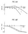
- diagnostic signal DS is an AC signal
- curves which define allowable limits of change are determined as indicated by the solid lines and are prestored in a memory 26M in the diagnostic decision part 26c shown in Fig. 3.
- the diagnostic signals DS of the frequencies f1, f2, ... f n are sequentially generated by the diagnostic signal generator 27 and the response signal RS at each frequency is provided via the signal extractor 29 to the diagnostic decision part 26c, wherein the amplitude ratio A′/A and the phase difference ⁇ ⁇ are calculated and are checked to see if they are within the allowable limits stored in the memory 26M.
- the amplitude ratio A′/A and the phase difference ⁇ ⁇ are calculated and are checked to see if they are within the allowable limits stored in the memory 26M.
- the waveform of the output signal RS of the synchronous detector 21, provided in response to the diagnostic signal DS is prestored, as a pattern corresponding to a fault of each part, in the memory 26M of the diagnostic decision part 26c for comparison with the waveform of the output signal RS of the synchronous detector 21 and in the case of coincidence, the corresponding faulty component is also output as the diagnostic result DRES.
- the waveforms of the diagnostic signal DS and the output signal RS of the synchronous detector 21 may also be displayed on a display for an operator to diagnose the fiber optic gyro. In such an instance, the displays may be provided in digital form, if the diagnostic signal DS is a DC signal.
- the diagnostic unit 26 may be formed by analog hardware.
- Fig. 7 illustrates in block form a second embodiment of the present invention, in which the parts corresponding to those in Fig. 1 are identified by the same reference numerals.
- the combiner 28 is provided between the output of the ramp generator 23 and the feedback phase modulator 24 and the diagnostic signal DS is added to the ramp voltage.
- the diagnostic unit 26 controls the diagnostic signal generator 27 to generate the diagnostic signal DS of the ramp waveform.
- a positive or negative ramp wave is selectively generated as the diagnostic signal DS.
- the diagnostic signal DS thus generated has the same amplitude as that of the output ramp wave signal of the ramp generator 23 and has a preset frequency. This diagnostic signal DS is superimposed on the output of the ramp generator 23.
- the diagnostic signal DS is applied to the feedback phase modulator 24 when the input angular rate is zero, a phase difference is introduced between the right-handed light and the left-handed light emitted from the optical fiber coil 16 as if an angular rate is input, and the ramp generator 23 generates such a ramp wave as to cancel the diagnostic signal DS.
- the output of the output circuit 25 at that time is input into the diagnostic unit 26 for deciding whether a correct output corresponding to the diagnostic signal DS can be obtained, and the diagnostic result is provided therefrom and is displayed on a display (not shown). Also in this case, it is possible to use an arrangement in which the output of the synchronous detector 21 is applied to the diagnostic unit 26 to diagnose the fiber optic gyro, depending on whether an output corresponding to the diagnostic signal DS can be obtained or not.
- Fig. 8 illustrates in block form a third embodiment of the present invention, in which phase modulating means for diagnostic use is provided and the ramp wave diagnostic signal DS is supplied thereto, although in Fig. 7 the ramp wave diagnostic signal DS is superimposed on the output of the ramp generator 23.
- a phase modulator for diagnostic use 38 is connected in series with the feedback phase modulator 24 in the optical integrated circuit 14 and the ramp wave diagnostic signal DS is applied directly to the phase modulator 38 from the diagnostic signal generator 27.
- the phase modulator 38 may also be connected in series with the bias phase modulator 18 as indicated by the broken lines 39.
- the phase modulator for diagnostic use 28 can be considered to be provided for injecting the diagnostic signal DS into the closed loop of the fiber optic gyro as is the case with the combiner 28 in the embodiments of Figs. 2 and 7.
- Fig. 9 illustrates in block form a fourth embodiment of the present invention, in which the ramp wave diagnostic signal DS from the diagnostic signal generator 27 is applied to the combiner 28, wherein it is superimposed on the bias phase modulating signal from the bias phase modulator driver 19, and the superimposed output is applied to the bias phase modulator 18.
- the fiber optic gyro of the present invention has the fault diagnostic function, and hence can be checked to see if it is normal or not, even after it is built in an apparatus, simply by providing a diagnostic instruction without the necessity of physically inputting the angular rate. Accordingly, the present invention is of great utility in practical use.
Landscapes
- Physics & Mathematics (AREA)
- Engineering & Computer Science (AREA)
- Power Engineering (AREA)
- Optics & Photonics (AREA)
- Electromagnetism (AREA)
- General Physics & Mathematics (AREA)
- Radar, Positioning & Navigation (AREA)
- Remote Sensing (AREA)
- Gyroscopes (AREA)
Claims (8)
- Lichtwellenleiter-Gyroskop, umfassend:
eine Lichtquelle (12) zur Emission eines Lichtstrahls zu einem optischen Weg;
eine Lichtwellenleiterspule (16) mit wenigstens einer Windung;
eine optische Teiler/Koppleranordnung (15) zum Aufspalten des Lichtstrahls von dem optischen Weg zur Eingabe in die beiden Enden der Lichtwellenleiterspule, zum Zusammenkoppeln der von den beiden Enden der Lichtwellenleiterspule nach Durchlaufen derselben als rechtsseitiger Lichtstrahl bzw. linksseitiger Lichtstrahl emittierten Lichtstrahlen, und zur Ausgabe des resultierenden Interferenzlichts zu dem optischen Weg;
eine Rückkopplungsphasenmodulationsanordnung (24), die in Reihe zwischen ein Ende der Lichtwellenleiterspule und die optische Teiler/Koppleranordnung geschaltet ist, um eine Phasendifferenz zwischen dem rechtsseitigen Lichtstrahl und dem linksseitigen Lichtstrahl zu bewirken;
eine photoelektrische Wandleranordnung (17), die das Interferenzlicht von dem optischen Weg erhält, um seine Intensität in ein elektrisches Signal umzusetzen;
eine Phasendetektoranordnung (21) zur Erfassung von Information hinsichtlich der Phasendifferenz zwischen dem rechtsseitigen Lichtstrahl und dem linksseitigen Lichtstrahl, die in dem elektrischen Signal von der photoelektrischen Wandleranordnung enthalten ist; und
eine Rampenwellengeneratoranordnung (23) zur Erzeugung einer Rampenwelle einer Frequenz entsprechend dem Pegel des Detektorsignals von der Phasendetektoranordnung,
wobei durch Lieferung der Rampenwelle an die Rückkopplungsphasenmodulationsanordnung (24) ein Regelkreis zur Ausführung einer Gegenkopplungsregelung gebildet wird derart, daß die Phasendifferenz zwischen dem rechtsseitigen Lichtstrahl und dem linksseitigen Lichtstrahl auf Null reduziert wird;
wobei das geregelte Lichtwellenleiter-Gyroskop dadurch gekennzeichnet ist, daß es einschließt
eine Diagnosesignalgeneratoranordnung (27) zur Erzeugung eines vorbestimmten Diagnosesignals (DS);
eine Signalkombiniereinrichtung (28; 38; 39) zum Einkoppeln des Diagnosesignals (DS) von der Diagnosesignalgenerartoranordnung (27) in den Regelkreis; und
eine Diagnoseeinrichtung (26), die als Antwort auf das Diagnosesignal (DS) ein Antwortsignal (RS) von dem Regelkreis erhält und auf der Grundlage dieses Antwortsignals (RS) eine Fehlerdiagnose ausführt. - Lichtwellenleiter-Gyroskop nach Anspruch 1, bei dem die Signalkombiniereinrichtung (28) eine zwischen die Phasendetektoranordnung (21) und die Rampenwellengeneratoranordnung (23) geschaltete Kombiniereinrichtung zur Überlagerung des Diagnosesignals (DS) mit dem Ausgangssignal der Phasendetektoranordnung (21) ist.
- Lichtwellenleiter-Gyroskop nach Anspruch 1, bei dem die Signalkombiniereinrichtung (28) eine zwischen die Rampenwellengeneratoranordnung (23) und die Rückkopplungsphasenmodulationsanordnung (24) geschaltete Kombiniereinrichtung zur Überlagerung des Ausgangssignals der Rampenwellengeneratoranordnung mit einer Rampenwelle für Diagnosezwecke von der Diagnosesignalgeneratoranordnung (27) als dem Diagnosesignal (DS).
- Lichtwellenleiter-Gyroskop nach Anspruch 1, bei dem die Signalkombiniereinrichtung (38; 39) eine Diagnosephasenmodulationsanordnung ist, die in Serie zwischen ein Ende der Lichtwellenleiterspule (16) und die optische Teiler/Koppleranordnung (15) geschaltet ist, und die Diagnosesignalgeneratoranordnung (27) eine Rampenwelle für Diagnosezwecke als das Diagnosesignal (DS) an die Diagnosephasenmodulationsanordnung zum Einspeisen der Rampenwelle in den Regelkreis liefert.
- Lichtwellenleiter-Gyroskop nach Anspruch 1, das ferner eine Grundphasenmodulationsanordnung (18) enthält, die in Serie zwischen ein Ende der Lichtwellenleiterspule (16) und die optische Teiler/Koppleranordnung (15) geschaltet ist, und eine Grundsignalgeneratoranordnung (19) zum Anlegen eines Grundphasenmodulationssignals an die Grundphasenmodulationsanordnung (18) derart, daß der rechtsseitige Lichtstrahl und der linksseitige Lichtstrahl, die die Lichtwellenleiterspule durchlaufen, eine Grundphase erhalten, die mit jeder Durchlaufzeit von Licht durch die Lichtwellenleiterspule wechselt, und bei dem die Signalkombiniereinrichtung (28) eine zwischen die Grundsignalgeneratoranordnung (19) und die Grundphasenmodulationsanordnung (18) geschaltete Kombiniereinrichtung zur Überlagerung des Diagnosesignals (DS) mit dem Grundphasenmodulationssignal ist.
- Lichtwellenleiter-Gyroskop nach Anspruch 1, 2, 3, 4 oder 5, bei dem das Antwortsignal (RS) von dem Regelkreis das Ausgangssignal der Phasendetektoranordnung (21) ist.
- Lichtwellenleiter-Gyroskop nach Anspruch 1, 2, 3, 4 oder 5, bei dem das Antwortsignal (RS) von dem Regelkreis das Ausgangssignal des Lichtwellenleiter-Gyroskops entsprechend der Rampenwelle ist.
- Lichtwellenleiter-Gyroskop nach einem der vorhergehenden Ansprüche, ferner umfassend eine Speicheranordnung (26M), in der eine Vielzahl von Antwortsignalwellenformen vorab gespeichert ist, von denen jede einer Antwort auf das vorbestimmte Diagnosesignal in Anwesenheit eines bestimmten Fehlers des Gyroskops entspricht, sowie eine Vergleichseinrichtung zum Vergleich des tatsächlichen Antwortsignals mit den vorgespeicherten Antwortsignalwellenformen zur Bestimmung eines besonderen Fehlers, falls ein solcher vorhanden ist.
Applications Claiming Priority (2)
| Application Number | Priority Date | Filing Date | Title |
|---|---|---|---|
| JP163162/90 | 1990-06-21 | ||
| JP2163162A JPH0752106B2 (ja) | 1990-06-21 | 1990-06-21 | 自己故障診断機能付光干渉角速度計 |
Publications (2)
| Publication Number | Publication Date |
|---|---|
| EP0462580A1 EP0462580A1 (de) | 1991-12-27 |
| EP0462580B1 true EP0462580B1 (de) | 1994-11-02 |
Family
ID=15768413
Family Applications (1)
| Application Number | Title | Priority Date | Filing Date |
|---|---|---|---|
| EP91109997A Expired - Lifetime EP0462580B1 (de) | 1990-06-21 | 1991-06-18 | Optischer Faserkreisel mit Selbstdiagnosefunktion |
Country Status (5)
| Country | Link |
|---|---|
| US (1) | US5108181A (de) |
| EP (1) | EP0462580B1 (de) |
| JP (1) | JPH0752106B2 (de) |
| CA (1) | CA2044850C (de) |
| DE (1) | DE69104912T2 (de) |
Families Citing this family (15)
| Publication number | Priority date | Publication date | Assignee | Title |
|---|---|---|---|---|
| US5386290A (en) * | 1992-04-30 | 1995-01-31 | Japan Aviation Electronics Industry Limited | Optical interferometric angular rate meter with a self-diagnostic capability |
| WO1994004969A1 (fr) * | 1992-08-24 | 1994-03-03 | Omron Corporation | Dispositif et procede de detection de defaillance |
| JP3011592B2 (ja) * | 1993-11-16 | 2000-02-21 | 日立電線株式会社 | 光ファイバジャイロの故障検出方法及び故障診断装置 |
| DE4447005A1 (de) * | 1994-12-29 | 1996-07-04 | Bosch Gmbh Robert | Vorrichtung zur Ermittlung einer Drehrate |
| US6732586B2 (en) | 1995-05-30 | 2004-05-11 | Matsushita Electric Industrial Co., Ltd. | Angular velocity sensor |
| US6705151B2 (en) | 1995-05-30 | 2004-03-16 | Matsushita Electric Industrial Co., Ltd. | Angular velocity sensor |
| US6912901B1 (en) | 1995-05-30 | 2005-07-05 | Matsushita Electric Industrial Co., Ltd. | Angular velocity sensor |
| EP0988507A2 (de) * | 1997-05-30 | 2000-03-29 | Honeywell Inc. | Verfahren und vorrichtung zur kontinuierlichen eingriffsfreien fehlerüberwachung |
| JP4843855B2 (ja) * | 2001-03-09 | 2011-12-21 | パナソニック株式会社 | 角速度センサ |
| US7274460B2 (en) * | 2004-06-02 | 2007-09-25 | Northrop Grumman Corporation | Stimulated rate optical power measurement in a fiber optic gyroscope |
| JP2007040764A (ja) * | 2005-08-01 | 2007-02-15 | Toyota Motor Corp | 光ファイバジャイロの異常検出装置 |
| JP5494477B2 (ja) * | 2008-04-10 | 2014-05-14 | パナソニック株式会社 | 慣性力センサ |
| CN102645230B (zh) * | 2012-04-11 | 2015-06-24 | 中航捷锐(北京)光电技术有限公司 | 光纤陀螺仪的故障检测方法及装置 |
| CN103884358B (zh) * | 2014-03-31 | 2016-06-01 | 北京控制工程研究所 | 一种数字闭环光纤陀螺全回路检测与仿真测试系统 |
| CN112595340B (zh) * | 2020-09-04 | 2024-11-12 | 北京理工导航控制科技股份有限公司 | 一种光纤陀螺仪在线故障检测方法 |
Family Cites Families (1)
| Publication number | Priority date | Publication date | Assignee | Title |
|---|---|---|---|---|
| US4998822A (en) * | 1987-03-27 | 1991-03-12 | Litton Systems, Inc. | Rotation rate nulling servo and method for fiber optic rotation sensor |
-
1990
- 1990-06-21 JP JP2163162A patent/JPH0752106B2/ja not_active Expired - Fee Related
-
1991
- 1991-06-17 US US07/716,280 patent/US5108181A/en not_active Expired - Lifetime
- 1991-06-18 DE DE69104912T patent/DE69104912T2/de not_active Expired - Lifetime
- 1991-06-18 EP EP91109997A patent/EP0462580B1/de not_active Expired - Lifetime
- 1991-06-18 CA CA002044850A patent/CA2044850C/en not_active Expired - Lifetime
Also Published As
| Publication number | Publication date |
|---|---|
| DE69104912T2 (de) | 1995-04-27 |
| DE69104912D1 (de) | 1994-12-08 |
| CA2044850A1 (en) | 1991-12-22 |
| US5108181A (en) | 1992-04-28 |
| EP0462580A1 (de) | 1991-12-27 |
| CA2044850C (en) | 1995-12-05 |
| JPH0452511A (ja) | 1992-02-20 |
| JPH0752106B2 (ja) | 1995-06-05 |
Similar Documents
| Publication | Publication Date | Title |
|---|---|---|
| US5108181A (en) | Fiber optic gyro with self-diagnostic function | |
| US5323415A (en) | Brillouin ring laser | |
| US6329648B1 (en) | Phase locked loop fiber optic sensor system | |
| EP0511684B1 (de) | Phasenmodulierter faseroptischer Kreisel | |
| US5386290A (en) | Optical interferometric angular rate meter with a self-diagnostic capability | |
| EP0476673A1 (de) | Optischer Faserkreisel | |
| JPH04503111A (ja) | 光フアイバジヤイロスコープ複数変調器位相差制御装置 | |
| GB2157823A (en) | Open loop thin film laser gyro | |
| US5116129A (en) | Digital phase ramp type fiber optic gyro | |
| JPH11287659A (ja) | 自己故障診断機能を有する光ファイバジャイロ | |
| EP0503600A1 (de) | Optische Abstandsmessvorrichtung | |
| JPH06103855B2 (ja) | 光ヘテロダイン受信装置 | |
| JPH09218130A (ja) | 周波数掃引誤差検出方法および回路、光周波数掃引光源、ならびに光周波数領域反射測定回路 | |
| US5098188A (en) | Method and apparatus for eliminating kerr effects in a ring gyro | |
| CA2061772C (en) | Synchronous detector | |
| US5345307A (en) | Linear phase ramp type fiber optic gyro having ramp reset and reset connection signals | |
| JP2514529B2 (ja) | 光干渉角速度計 | |
| JPS63128225A (ja) | 変調式光フアイバジヤイロ | |
| JP2532326B2 (ja) | 光干渉角速度計 | |
| JP2997826B2 (ja) | マルチヘッド型光学式変位計 | |
| EP0412468B1 (de) | Synthetische Sägezahnsteuerung für Faserkreisel | |
| JPH10111133A (ja) | 異常検出機能を持つ光干渉角速度計 | |
| EP0829013A1 (de) | Fiberoptischer messwandler | |
| JPS61235719A (ja) | フアイバ−・干渉計 | |
| AU710660B2 (en) | Fibre optic transducer |
Legal Events
| Date | Code | Title | Description |
|---|---|---|---|
| PUAI | Public reference made under article 153(3) epc to a published international application that has entered the european phase |
Free format text: ORIGINAL CODE: 0009012 |
|
| 17P | Request for examination filed |
Effective date: 19910618 |
|
| AK | Designated contracting states |
Kind code of ref document: A1 Designated state(s): DE FR GB |
|
| 17Q | First examination report despatched |
Effective date: 19930609 |
|
| GRAA | (expected) grant |
Free format text: ORIGINAL CODE: 0009210 |
|
| AK | Designated contracting states |
Kind code of ref document: B1 Designated state(s): DE FR GB |
|
| REF | Corresponds to: |
Ref document number: 69104912 Country of ref document: DE Date of ref document: 19941208 |
|
| ET | Fr: translation filed | ||
| PLBE | No opposition filed within time limit |
Free format text: ORIGINAL CODE: 0009261 |
|
| STAA | Information on the status of an ep patent application or granted ep patent |
Free format text: STATUS: NO OPPOSITION FILED WITHIN TIME LIMIT |
|
| 26N | No opposition filed | ||
| REG | Reference to a national code |
Ref country code: GB Ref legal event code: IF02 |
|
| PGFP | Annual fee paid to national office [announced via postgrant information from national office to epo] |
Ref country code: FR Payment date: 20100709 Year of fee payment: 20 |
|
| PGFP | Annual fee paid to national office [announced via postgrant information from national office to epo] |
Ref country code: GB Payment date: 20100616 Year of fee payment: 20 Ref country code: DE Payment date: 20100616 Year of fee payment: 20 |
|
| REG | Reference to a national code |
Ref country code: DE Ref legal event code: R071 Ref document number: 69104912 Country of ref document: DE |
|
| REG | Reference to a national code |
Ref country code: DE Ref legal event code: R071 Ref document number: 69104912 Country of ref document: DE |
|
| REG | Reference to a national code |
Ref country code: GB Ref legal event code: PE20 Expiry date: 20110617 |
|
| PG25 | Lapsed in a contracting state [announced via postgrant information from national office to epo] |
Ref country code: GB Free format text: LAPSE BECAUSE OF EXPIRATION OF PROTECTION Effective date: 20110617 |
|
| PG25 | Lapsed in a contracting state [announced via postgrant information from national office to epo] |
Ref country code: DE Free format text: LAPSE BECAUSE OF EXPIRATION OF PROTECTION Effective date: 20110619 |