EP0462565B1 - Multiwindow display control method and apparatus - Google Patents
Multiwindow display control method and apparatus Download PDFInfo
- Publication number
- EP0462565B1 EP0462565B1 EP91109959A EP91109959A EP0462565B1 EP 0462565 B1 EP0462565 B1 EP 0462565B1 EP 91109959 A EP91109959 A EP 91109959A EP 91109959 A EP91109959 A EP 91109959A EP 0462565 B1 EP0462565 B1 EP 0462565B1
- Authority
- EP
- European Patent Office
- Prior art keywords
- pixel data
- group
- frame memory
- memory control
- display
- Prior art date
- Legal status (The legal status is an assumption and is not a legal conclusion. Google has not performed a legal analysis and makes no representation as to the accuracy of the status listed.)
- Expired - Lifetime
Links
Images


Classifications
-
- G—PHYSICS
- G09—EDUCATION; CRYPTOGRAPHY; DISPLAY; ADVERTISING; SEALS
- G09G—ARRANGEMENTS OR CIRCUITS FOR CONTROL OF INDICATING DEVICES USING STATIC MEANS TO PRESENT VARIABLE INFORMATION
- G09G5/00—Control arrangements or circuits for visual indicators common to cathode-ray tube indicators and other visual indicators
- G09G5/14—Display of multiple viewports
Definitions
- the present invention relates to a multiwindow display control method and apparatus for a control of a multiwindow display.
- a multiwindow display provides an environment in which a plurality of windows are displayed on a single screen, whereby users can efficiently carry out various jobs at the same time, and the multiwindow display has become essential in the construction of a human interface such as a work station.
- a plurality of frame memories each of the same size as a display screen are provided, or a single frame memory having a size larger than the display screen is provided.
- each frame memory stores pixel data of a single window
- the larger size frame memory stores pixel data of a plurality of windows.
- conventionally hardware is used to directly synthesize the pixel data of each window in the frame memory, to thereby obtain a multiwindow display screen image which is displayed on a display screen.
- the hardware displays the windows on the display screen, based on the window display control data, by switching the reading location from the frame memory synchronously with the display timing.
- EP-A-0 349 455 discloses a method of displaying nested overlays, and the order or precedence of multiple nested overlays is selected and altered. This document discloses a plurality of windows, but no plurality of groups of windows.
- US-A-4 688 167 discloses the representation on the displayed screen without any overlapped portions of windows (view-ports), the areas are positioned side-by-side, and are divided by boundary lines. Therefore, the display control of display is performed within each window (view-port) area based on priority only.
- EP-A-0 249 696 discloses the control of a plurality of windows but no plurality of groups thereof and consequently it does not indicate the control of groups of windows.
- each page constitutes a group of windows including a plurality of windows.
- an overlapping display control is necessary, and in such an overlapping display, a plurality of groups of windows are simultaneously displayed on a screen.
- the overlapping display control is carried out by a single variable, i.e., a priority of each window with respect to the display order regardless of the group of windows to which the windows belong, and therefore, it is very difficult to carry out an overlapping display of the groups of windows.
- a priority of each window with respect to the display order regardless of the group of windows to which the windows belong
- the load on software is very heavy and thus the advantage of a satisfactory high speed display by hardware cannot be obtained.
- a group of windows is also hereinafter referred to as a group window.
- an object of the present invention is to solve the above mentioned problem and to provide a means capable of carrying out a simple control of a change of a display of a plurality of groups of windows each including a plurality of windows.
- a multiwindow display control method for controlling a display of multiwindows consisting of a plurality of groups of windows each including a plurality of windows, characterized in that: as parameters for controlling a display of said windows, each of said windows is provided with; a group number (GN) for identifying a group of windows to which the window belongs; and a priority number (PN) for indicating a priority of a display in said group of windows; the display control among said windows being carried out by combining one of said group numbers and one of said priority numbers assigned to each of said windows.
- GN group number
- PN priority number
- a multiwindow display control apparatus for controlling display of multiwindows consisting of a plurality of groups of windows each including a plurality of windows, comprising: a plurality of frame memory control units each storing pixel data to be displayed on one of the windows, a first group number of a group of windows to which the window belongs, and a priority number for identifying a display priority of the windows included in the same group of windows; an outline generating unit for generating second group numbers each identifying one of the group of windows; a pixel data arbitration unit, operatively connected to the frame memory control units and to the outline generating unit, for determining a group of windows having the first group number which coincides with the second group number, and for determining a window to be displayed having a highest priority number among the determined group of windows; and a display unit, operatively connected to the pixel data arbitration unit, for displaying pixel data of the determined window.
- a conventional hardware window system a general window basic operation, a group window basic operation for explaining the subject of the present invention, and a page turning operation as an example of an application of an overlapping change operation in the basic operation of the group window will be first described with reference to Fig. 23, Figs. 24A to 24D, Figs. 25A to 25D, and Figs. 26A to 26C, respectively.
- the conventional hardware window system has a single frame memory FM having a capacity larger than the region to be displayed.
- the system may have a plurality of frame memories each having a window with a capacity equal to the region to be displayed.
- a plurality of windows #1, #2, and #3 are stored in the frame memory FM shown in Fig. 23, and each window has the same size as the region to be displayed.
- Each window stores pixel data to be displayed as shown by dots or slash lines in the figure, and a multiwindow display screen image is obtained by reading data of each window from the frame memory FM in synchronization with a raster scan of a CRT display DSP, and by synthesizing the read data by hardware.
- a control memory CM is provided to control the reading operation, and window display control data such as a storing location of each window, display location of each window on the CRT display DSP, display priorities of the windows when overlapped, and so forth, are set in the control memory CM.
- window display control data such as a storing location of each window, display location of each window on the CRT display DSP, display priorities of the windows when overlapped, and so forth, are set in the control memory CM.
- the window #3 has the highest priority and the window #1 has the lowest priority, when these windows #1 to #3 are overlappingly displayed simultaneously on the CRT display DSP.
- the control memory CM controls a switch SW connected to the windows #1 to #3 so that the windows are displayed on the CRT display DSP.
- the control of the switching is effected in accordance with display clock signals obtained from the storing location, the display location, and the overlapping priority of each window.
- the basic operations as shown in Figs. 24A to 24D i.e., the basic operations such as a generation/erasing of a window as shown in Fig. 24A, a movement of a window as shown in Fig. 24B, a change of an overlapping as shown in Fig. 24C, or a change of the size of a window as shown in Fig. 24D, can be carried out.
- a plurality of windows W11 to W13 are included in one group of windows, and windows W21, W22, ... are included in another group of windows.
- These groups of windows are assumed to be pages of a book, and by turning the page including the windows W11 to W 13 through a touch panel or a mouse, the next page including the windows W21, W22, ... is partially and gradually displayed.
- This page turning operation is similar to the actual turning of the pages of a book.
- Figure 1 is a block diagram showing a principle of a multiwindow display control apparatus according to the present invention.
- two kinds of variables are employed for controlling an overlapping display of a group of windows.
- These two kinds of variables are group numbers each identifying a group of windows including a plurality of windows, and priority numbers each indicating the display order for the windows in the same group of windows when the windows are to be overlappingly displayed.
- the overlapping display control is carried out by a combination of the group number and the priority number. Namely, a plurality of windows are grouped by a group number; the group to be displayed in each pixel region on the display screen is determined in accordance with the group number; and the overlapping control of the windows is carried out in accordance with the priority number thereof in each group of windows.
- the multiwindow display control apparatus comprises an outline generating unit 10 for generating the group numbers for identifying a plurality of windows, a plurality of frame memory control units 12-1 to 12-n each storing pixel data to be displayed on the corresponding window, a pixel data arbitration unit 14 for selecting, based on the combination of a group number and a priority number indicating the order of the overlapping display in the same group of windows, picture data output from these frame memory control units 12-1 to 12-n, and a display interface unit 16 for providing an interface with a display screen.
- a processor for effecting data processing, a main memory, various peripheral units and so forth, not shown in Fig. 1, are connected to a system bus 17.
- the outline generating unit 10 generates, each time a pixel is to be displayed and under the control of the processor through the system bus 17, a group number which is the first variable indicating that a plurality of windows in the group of windows are to be treated as one group.
- the outline generating unit 10 has a group number storing frame memory 11 for storing the group numbers corresponding, for example, to respective pixels.
- the outline generating unit 10 may have a control register for individually generating a group number region for each group of windows, by setting data in the control register as later described with reference to Fig. 9.
- the outline generating unit 10 generates a group number of a group of windows to be displayed on the display for each pixel.
- Each frame memory control unit 12-i outputs a group number belonging to each group of windows, a priority number indicating the display priority order in the same group, and pixel data.
- the frame memory control unit 12-i also generates a display enable range of a window and so forth.
- the picture data arbitration unit 14 comprises pixel data arbitration circuits 15-i corresponding to the respective frame memory control units 12-i, and each picture pixel data arbitration circuit 15-i determines, for each pixel, whether or not the group number generated by the outline generating unit 10 coincides with the group number output from the frame memory control unit 12-i, and further, compares the priority number output from the frame memory control units 12-i belonging to the same group, as later described in more detail with reference to Figs. 15 to 21. Accordingly, the pixel data output from the frame memory control units are arbitrated by the pixel data arbitration circuits 15-i so that pixel data of one selected frame memory unit 13-i is output from the pixel data arbitration unit 14.
- the display interface unit 16 converts the pixel data output from the pixel data arbitration unit 14 into display signals.
- each of the frame memory control units 12-i may carry out the display position control of each window by using absolute coordinates of the regions corresponding to the display screen, or instead may carry out this control by using relative coordinates with respect to the region occupied by the group of windows.
- the window overlapping control is carried out by a combination of a group number and a priority number indicating the order of display priority in the same group.
- a plurality of windows can be linked in the same group of windows, and further, desired windows in the same group of windows can be displayed in accordance with the display priorities thereof.
- a same group number is provided to these windows, and a priority number is designated to each window, whereby the windows in each group are linked so that they can be operated as a group of windows, and thus various operations can be carried out by a simple control.
- FIGS. 2A to 2C are block diagrams showing a multiwindow display control apparatus according to an embodiment of the present invention. Note, throughout the drawings, the same reference numerals and symbols represent the same parts.
- a first page consists of windows W10, W11, and W12 as shown in Fig. 2A
- a second page consists of windows W20 and W21 as shown in Fig. 2B.
- These pages are to be overlapped as if they are pages of a book. It is assumed that the background of the overlapping pages is a window W30.
- a group number GN is set for each pixel of the subject to be displayed.
- the group number GN of the background part is assumed to be "3”
- the group number GN for the first page is assumed to be "1”
- the group number GN for the next page is assumed to be "2”. Therefore, in accordance with the page turning operation as illustrated by an arrow, the region in which the group number GN is "2" is gradually increased.
- the group number storing frame memory 11 is scanned, as shown in the figure by dotted lines, synchronously with the raster scan on the display, and the group number GN for each pixel is output from the frame memory 11 to the pixel data arbitration unit 14.
- Picture data, a group number GN, and a priority number PN are always output from the frame memory unit 13-i in each frame memory control unit 12-i to the pixel data arbitration unit 14.
- the pixel data arbitration unit 14 selects pixel data which has the highest priority in the outputs of a frame memory control unit 12-i having a group number GN which coincides with the group number GN from the group number storing frame memory 11, and sends the selected pixel data to the display interface unit 16.
- a group number GN 2 is output from the frame memory 11, and the window W20 or W21 of the second page shown in Fig. 2B is displayed.
- each of the frame memory units 13-i merely fixedly stores data relating to the own window.
- control registers are provided to correspond to the respective group numbers, and addresses of the regions of the group of windows are stored in the control registers.
- signals representing individual group number regions i.e., the group window rectangular region signals of the regions occupied by a group of windows of the respective group numbers, are generated from the control registers and these group window rectangular region signals are used for outputting the group numbers from the outline generator 10 (See Fig. 9).
- the pixel data arbitration unit 14 comprises a plurality of pixel data arbitration circuits 15-i corresponding to the respective frame memory control units 12-i, as shown in Fig. 1.
- Each of the pixel data arbitration circuits 15-i inputs and outputs a group number signal, a priority number signal, and a pixel data signal.
- each pixel data arbitration circuit 15-i inputs and outputs the group window rectangular region signal.
- the outline generating unit 10 there are two embodiments as mentioned before, i.e., one in which the group number storing frame memory 11 is provided, and another in which control registers are provided for generating the group window region signals.
- a display position control of a window there are two embodiments, i.e., one in which the control is carried out by an absolute coordinate on the display screen, and another in which the control is carried out by a relative coordinate with respect to a region occupied by a group of windows.
- the pixel data arbitration circuits 15-i can be constructed by providing calculators of two systems for calculating picture data to output the calculated result (See Fig. 17), and for displaying a cursor and so forth, a pixel data forcible changing mechanism (See Fig. 18) can be provided.
- the present invention can be embodied by combining these various embodiments.
- a first embodiment is shown in Fig. 8 in which the group number storing frame memory 11 is employed for generating the group number signal indicating the group number corresponding to each group window display region, in a state where a plurality of groups of windows each consisting of a plurality of windows are arbitrarily overlapped and displayed on a display.
- FIG. 9 A second embodiment is shown in Figs. 9 to Fig. 13 in which the group number signal is generated by setting an address in the control register.
- FIG. 14 A third embodiment is shown in Fig. 14 in which the outline generating unit 10 outputs not only the group number signal but also a group window region signal to be used for a display control by a relative coordinate.
- FIG. 15 and Fig. 16 A fourth embodiment is shown in Fig. 15 and Fig. 16 in which the pixel data arbitration units 15-i have a daisy chain structure and pixel data of two systems are exchanged.
- a fifth embodiment is shown in Fig. 17 in which a calculating mechanism of pixel data of two systems is added to the fourth embodiment.
- FIG. 18 A sixth embodiment is shown in Fig. 18 in which a pixel data forcible changing mechanism is added to the fourth embodiment or the fifth embodiment.
- a seventh embodiment is shown in Fig. 19 in which the third embodiment of the outline generating unit 10 and the fourth embodiment of the pixel data arbitration circuit 15-i are combined.
- FIG. 20 An eighth embodiment is shown in Fig. 20 in which the third embodiment of the outline generating unit 10 and the fifth embodiment of the pixel data arbitration circuit 15-i are combined.
- FIG. 21 A ninth embodiment is shown in Fig. 21 in which the third embodiment of the outline generating unit 10 and the sixth embodiment of the pixel data arbitration circuit 15-i are combined.
- FIG. 22 A tenth embodiment is shown in Fig. 22 in which the pixel data arbitration circuit 15-i has a bus structure.
- Figure 4 shows a construction of the frame memory control unit 12-i according to an embodiment of the present invention.
- the frame memory control unit 12-i comprises a group number register (GNR) 41 for storing a group number GN allocated to the window corresponding to this frame memory control unit, a priority number register (PNR) 42 for storing a priority number allocated to the window, a display control unit 43, used only when the display is effected by relative coordinates with respect to the group window region on the display screen, for instructing the frame memory unit 13 on the display range and position on the display screen, the frame memory unit 13 for storing pixel data of the window to be displayed on the display, and a display enable region signal generating circuit 44, optionally provided, for generating a signal to limit the range actually displayed on the display to an arbitrary shape, in accordance with preset masking data.
- GNR group number register
- PNR priority number register
- Figure 5 shows a block diagram of the display control unit 43 shown in Fig. 4.
- the display control unit 43 in Fig. 5 is used when the display position control is carried out by the relative coordinates with respect to the group window region.
- the display control unit 43 receives a group window region signal GW from the pixel data arbitration unit 14, and based on the group window region signal GW, a horizontal synchronization signal HS, a vertical synchronization signal VS, a pixel clock signal DCK, and signals DSPX and DSPY indicating the range of the group window region in the X direction and in the Y direction are generated.
- counters 51-1 and 51-2 for counting the group window region signal GW in response to the pixel clock DCK and the horizontal synchronization signal HS through the AND gates 50-1 and 50-2 respectively.
- the output of the counter 51-1 is the X coordinate GWX of the group window region
- the output of the counter 51-2 is the Y coordinate GWY of the group window region.
- a window display start X coordinate register 53 a window display end X coordinate register 54, a window display start Y coordinate register 55, and a window display end Y coordinate register 56, connected to the system bus 17.
- a start coordinate or an end coordinate of the window handled by the frame memory control unit 12-i is preset.
- the outputs of the flip-flops 58-1 and 58-2 become the signals DSPX and DSPY indicating the range of the group window region.
- the frame memory unit 13 shown in Fig. 4 has a construction as shown in Fig. 6.
- 61 is a bus interface circuit having an interface with address/data lines and control signal lines in the system bus 17, and a frame memory 67 is used for storing pixel data and is constructed by a dual port dynamic random access memory (RAM) having random ports and serial ports.
- RAM dynamic random access memory
- a refresh address/control signal generating circuit 62 is used for generating an address at the time of a refreshing of the frame memory 67 and control signals relating to the refreshing address.
- a serial port address/control signal generating circuit 63 is a circuit for receiving the signals DSPX and DSPY, from the display control unit 43, indicating the range of the group window region in the X direction and in the Y direction, and for generating an address of a serial port which outputs pixel data from the frame memory 67 and control signals.
- a timing generating circuit 65 is a circuit for generating a refresh timing of the dynamic RAM constituting the frame memory 67, a random port access timing by an external CPU and so forth, and a serial port access timing.
- a timing arbitration circuit 66 is a circuit for arbitrating the timing output from the timing generating circuit 65, and for controlling a selector 64.
- a pixel data multiplexing circuit 68 is used for multiplexing digital pixel data output from several serial ports in accordance with a pixel clock frequency.
- Pixel data to be displayed on the window is written into the frame memory 67 through the system bus 17 and the bus interface circuit 61 by processing from an external processor (CPU) and so forth, and pixel data is read from a serial port of the frame memory 67 by the signal generated from the serial port address/control signal generating circuit 63, and finally, in response to the pixel clock frequency, pixel data PD n is output from the pixel data multiplexing circuit 68.
- CPU central processing unit
- Figure 7 shows a block diagram of the display interface unit 16 according to an embodiment of the present invention.
- the display interface unit 16 comprises a D/A converter 71, a display synchronization signal generating circuit 72, and a display driving circuit 73.
- the D/A converter 71 is used for converting a digital signal of the pixel data PD, which is the output of the final stage pixel data arbitration circuit, into an analog signal.
- the display synchronization signal generating circuit 72 is used for preparing a horizontal synchronization signal or a vertical synchronization signal synchronized with a raster scan, and the display driving circuit 73 synthesizes the output of the D/A converter 71 and the output of the display synchronization signal preparing circuit 72 to generate a display signal.
- Figure 8 shows the first embodiment of the outline generating unit 10.
- a bus interface circuit 81 has an interface with the address/data lines and the control lines in the system bus 17, and the group number storing frame memory 11 is constructed by a dual port dynamic RAM having a random port and a serial port.
- a refresh address/control signal generating circuit 82 is used for generating an address of the group number storing frame memory 11 when it is refreshed, and a control signal related to the refreshing address, and a serial port address/control signal generating circuit 83 is used for generating an address and a control signal for a serial port from which a group number corresponding to pixel data is output.
- a timing generating circuit 85 is used for generating a refresh timing of the dynamic RAM which constructs the group number storing frame memory 11, a timing of an access of the random port by an external CPU and so forth, and a timing of a serial port access.
- a timing arbitration circuit 86 is used for arbitrating the output timings from the timing generating circuit 85 to control a selector 84. When the timings are in competition, an arbitration is carried out of the priority order from a serial port access timing, through a refresh timing, to a random port access timing.
- a pixel data multiplexing circuit 87 is used for multiplexing, in accordance with the pixel clock frequency, digital data having a group number GN corresponding to respective pixels output from several serial ports.
- Group numbers are written into the group number storing frame memory 11 through the system bus 17 and the bus interface circuit 81 by accessing from an external CPU and so forth, and a group number is read from the serial port of the group number storing frame memory 11, by a signal generated from the serial port address/control signal generating circuit 83, and a group number GN for each pixel is finally output by the pixel data multiplexing circuit 87 in response to the pixel clock frequency.
- various types of and arbitrary shaped group window regions can be generated, since the writing/updating of the group number into the group number storing frame memory 11 is carried out by software control by a processor.
- the group number signals can be generated by hardware instead of generating the group number signals by accessing the group number storing frame memory 11 shown in Fig. 8.
- the outline generating unit 10 shown in Fig. 9 comprises a display enable region address generating unit 91 for generating display addresses in the horizontal direction X and in the vertical direction Y, to be displayed on the display, a group window rectangular region generating unit 92 for generating rectangular region signals for the respective group windows GW#0, GW#1, GW#2, ..., and GW#n by the above-mentioned display addresses X and Y and values set by a processor connected through the system bus 17, a special region generating unit 93 for generating special group window region signals such as page turning pattern signals, a display priority sorting switch unit 94 for switching the group window region signals from a higher order of the display priority to a lower order of the display priority, a display priority determining unit 95 for determining a group window region signal having the highest priority among the effective plural group window region signals output from the display priority sorting switching unit 94 to enable the corresponding output signal, and a group number register unit 96 for outputting a group number GN which is set by the processor during
- the group window region signal is a signal indicating the maximum range which can be occupied by the grouped windows in the group of windows.
- the group window region signal is obtained by synthesizing the X direction signal S X and the Y direction signal S Y in accordance with the horizontal synchronization signal and the vertical synchronization signal.
- the X direction signal S X conforms with the X-direction side of the region GW0
- the Y direction signal S Y conforms with the Y-direction side of the region GW0.
- the signals output from the priority sorting switch unit 94 shown in Fig. 9 are, as shown in Fig. 10B for example, the respective group window region signals GW1 and GW2 arranged in the display priority order.
- the display priority determining unit 95 determines, as shown in Fig. 10C, that only the group window region signal having the highest priority is enabled.
- the group number register unit 96 replaces these group window region signals GW1 and GW2 with the group number signals GN1 and GN2, as shown in Fig. 10D, which are the values preset in the group number register 96.
- Figure 11 shows an example of the construction of the group window rectangular region generating unit 92 in the outline generating unit 10.
- the group window rectangular region generating unit 92 comprises region generating circuits 110-0 to 110-n corresponding to the respective group windows. These region generating circuits have the same structure having a group window display start X coordinate register 111, a group window display end X register 112, a group window display start Y coordinate register 113, and a group window display end Y register 114. In these registers, a start coordinate of the upper left and the end coordinate of the lower right of the rectangular region are set by a processor through the system bus 17.
- a comparator 115-1 compares the X address generated by the display enable region address generating unit 91 shown in Fig. 9 and the value in the group window display start X coordinate register 111, and when they coincide, a flip-flop 116-1 is set. When the X address coincides with the value of the group window display end X coordinate register 112, the flip-flop 116-1 is set.
- the special region generating unit 93 shown in Fig. 9 is used for generating a pattern of a special region other than a rectangular region.
- the special pattern is, for example, that used in the page turning operation when the group window rectangular region signals GW are used for determining the relative coordinates of the windows.
- the special region generating unit 93 has a construction as shown, for example, in Fig. 12.
- an X address counter 120 for counting pixel clocks DCK for each horizontal synchronization signal HS
- a Y address counter 121 for counting the horizontal synchronization signals HS for each vertical synchronization signal VS
- a change point coordinate memory 123 in which a set of coordinates indicating the boundaries of the group window region (referred to as change point coordinates) for each line are stored.
- the value read from the change point coordinate memory 123 and the output of the X address counter 120 are compared by a comparator 124, and when they coincide, a flip-flop 125 is set.
- the output of the flip-flop 125 is sent, as is or through an inverter 126 in accordance with a selection by a processor, to the display priority sorting switch unit 94, and is used as a signal of a group window region having a special shape.
- the special region generating unit 93 has a construction as shown in Fig. 13. Assuming that the size of the display screen is m dots x n lines.
- the change point coordinate memory 123 stores several sets which each include X coordinate values from the first line to the n-th line. In the example shown in Fig. 13, sets of the change point coordinates from first frame to ⁇ -th frame can be stored.
- the group window region signals GW are generated in such a way that, in the first line, the group window region starts or ends when the X address becomes 1000, and in the second line, the group window region starts or ends when the X address becomes 970. This is the same for the other lines.
- a region signal GWi or GWj is generated as shown in Fig. 13.
- the pixel data arbitration unit 14 and each frame memory control unit 12-i shown in Fig. 1 must know the position of the region occupied by the group window.
- the output signals of the group window rectangular region generating unit 92 i.e., the group window region signals GW#0, GW#1, GW#2, ..., and GW#n, are output to the pixel data arbitration unit 14 in the multiwindow display control apparatus shown in Fig. 1, and a corresponding one of these signals GW#0, GW#1, GW#2, ..., and GW#n is sent to each frame memory control unit 12-i through the pixel data arbitration unit 14.
- the circuit construction other than this output function is the same as that of the second embodiment shown in Fig. 9.
- the third embodiment has an advantage in that, when the display position of the group window is to be changed, each frame memory control unit 12-i can manage each window by the relative coordinates with respect to the group window region.
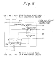
- Figure 15 shows an example of the pixel data arbitration circuit 15-n in the pixel data arbitration unit 14 having the daisy chain structure as shown in Fig. 3A.
- the signals of a group number GN n-1 , a priority number PN n-1 , and pixel data PD n-1 output from the n-1 th pixel data arbitration circuit become inputs of the n-th pixel data arbitration circuit 15-n.
- the signals of a group number GN n , a priority number PN n , pixel data PD n , and a display enable indication signal DE n indicating whether the pixel data PD n is effective or invalid and which are output from the n-th stage frame memory control unit, become inputs of the n-th pixel data arbitration circuit 15-n.
- the comparator 151 determines whether or not the group numbers GN n-1 and GN n coincide, and the comparator 152 determines whether or not the priority number PN n is larger than the priority number PN n-1 which has been sent from the previous stage.
- the output of the AND gate 153 becomes "H"
- the 2-1 selector 154 selects the signal of the B system and outputs it to the (n+1)-th stage pixel data arbitration circuit.
- the group number GN is not changed, the priority number PN and the pixel data PD are changed from those of the (n-1)-th stage to PN n and PD n of the n-th stage.
- PD1 to PD6 are pixel data
- GN1 to GN6 are group numbers
- PN1 to PN6 are priority numbers
- CNR is a group number register
- PNR is a priority number register
- FM is a frame memory unit 13-i for storing pixel data
- DE is a signal indicating validity of the display, i.e., when "1", the display is valid, and when "0", the display is invalid.
- each of the pixel data PD1 to PD6 includes four pixels, and the respective pixel data flow serially in synchronization with the pixel clock. To facilitate the processing speed, it is possible to process several pixels as one with parallel data during the process up to the final output.
- the outline generating unit 10 generates pixel data PD1 of the background, group numbers GN1 of "2", “1", “3”, and “1" for the respective pixels, and lowest priority numbers PN1 which are all "0".
- the pixel data arbitration circuit 15-1 receives the signals PD1 , GN1 , and PN1 pixel by pixel, finds a coincidence between the group number GN1 and a value "1" stored in the group number register GNR, and compares the priority number PN1 corresponding to the pixel data having the group number GN1 equal to the value in the group number register GNR.
- the group numbers of the second and fourth pixels are the same as the value "1" in the group number register GNR.
- the priority number register PNR in the frame memory control unit 12-1 stores "1", which is larger than the "0" in the priority numbers PN1 , and the display enable indication DE of the corresponding pixel is valid ("1")
- the corresponding pixel data and the priority numbers of the PN1 output from the outline generating unit 10 are replaced by the pixel data stored in the frame memory FM and the priority number of "1" in the priority number register PNR in the frame memory control unit 12-1.
- the replaced pixel data and the priority numbers are then output as pixel data PD2 and a priority number PN2 , from the pixel data arbitration circuit 15-1.
- the group number of the first pixel coincides with the value "2" in the group number register GNR, and therefore, by a similar comparison, the pixel data and a priority number of the first pixel output from the pixel data arbitration circuit 15-1 are replaced by the pixel data and the priority number in the frame memory control unit 12-2, and thus the pixel data arbitration circuit 15-2 outputs the pixel data PD3 and the priority numbers PN3 as illustrated.
- pixel data and priority numbers are replaced by the corresponding one of the pixel data arbitration circuit 15-1 to 15-5, and finally, pixel data having a group number which coincides with the group number generated from the outline generating unit 10, having the largest priority number, and having a display enable indication which indicates a validity of the display, are output and displayed through the display interface unit 16.
- a specific effect of this fourth embodiment employing the daisy chain structure is the enabling of a high transfer speed, and a reduction of the number of signal lines by multiplexing, since the transfer distance of signals and the synchronization among the signals are limited to between adjacent boards of the pixel data arbitration circuits. That is, because of the short distance between adjacent boards, and because each board independently performs a synchronization of timing of a receiving signal to transmit it to the next board, the requirement for system design relating to the timing is very loose so that the frequency of the transmitted signal can be made extremely high. Therefore, the signals can be transmitted by multiplexing, resulting in the decrease of the signal lines.
- Figure 17A shows a second example of the pixel data arbitration circuit in the pixel data arbitration unit 14 having a daisy chain structure.
- reference numeral 177 is a pixel data calculating unit having an A terminal and a B terminal as inputs.
- the pixel data calculating unit 177 selects the pixel data PD n output from the n-th stage frame memory control unit 12-n to be output as the pixel data PD n
- the calculating unit 177 selects the pixel data PD n-1 output from the previous stage pixel data arbitration circuit 15-(n-1) to be output as the pixel data PD n .
- the calculating unit 177 When the A terminal is at the "H” level and the B terminal is at the "L” level, the calculating unit 177 becomes a circuit having a raster operation function such as AND, OR, inversion, etc. between the two input data.
- a raster operation function such as AND, OR, inversion, etc. between the two input data.
- the kinds of the logical calculation in the raster operation can be instructed from, for example, an external processor not shown in the figure.
- the pixel data arbitration circuit 15-n shown in Fig. 17 is the same as that of the fourth embodiment explained with reference to Fig. 15. Therefore, an explanation thereof is omitted, and only the portions relating to the pixel data PD n-1 and PD n are explained.
- the pixel data calculating unit 177 selects the signal PD n from the n-th stage frame memory control unit 12-n and outputs it to the (n+1) system, and as a result, the pixel data is replaced from the PD n-1 output from the (n-1)-th stage pixel data arbitration circuit 15-(n-1) to the PD n output from the n-th stage frame memory control unit 12-n.
- the A terminal of the pixel data calculating unit 177 becomes "H” and the B terminal becomes "L”, through AND gates 174 and 175. Then, the pixel data calculating unit 177 performs a predetermined calculation among the pixel data PD n-1 of the (n-1)-th stage and the pixel data PD n of the n-th stage, and outputs the calculated result to the (n+1)-th stage.
- Figure 17B shows an example of the pixel data calculating unit 177 in the circuit shown in Fig. 17A.
- the pixel data calculating unit 17B includes a distributor 21, a fade-in/fade-out calculating circuit 22, a raster operation calculating circuit 23, and a switch 27.
- the raster operation calculating circuit 23 includes, for example, sixteen logic circuits OR, AND, NAND, etc.
- the fade-in/fade-out calculating circuit 22 includes two multipliers 25 and 26, and an adder 26.
- the distributor 21 receives the priority numbers PD n-1 and PD n and distributes them to the fade-in/fade-out calculating circuit 22 and to each logic circuits in the raster operation calculating circuit 23.
- multiplying coefficients c1 and c2 are set by a processor through the system bus 17.
- the multiplying coefficients c1 and c2 are between 0 and 1.
- the switch 27 selects, under the control of the processor through the system bus 17, one of the outputs from the system bus 17, one of the outputs from the fade-in/fade-out circuit 22 and the logic circuits in the raster operation calculating circuit 23.
- the priority number PD n output from the fade-in/fade-out calculating circuit 26 is gradually changed.
- the switch 27 selects the output form the fade-in/ fade-out calculating circuit 26, the screen transition of fade in or fade out can be realized.
- the sixteen raster operations are as follows.
- This fifth embodiment (5) provides a specific effect in that a screen transition such as fade in, fade out and so forth can be easily realized.
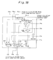
- Figure 18 shows an example of the pixel data arbitration circuit 15-n having a daisy chain structure in the pixel data arbitration unit 14, in which a pixel data forcible changing mechanism is provided.
- a forcible change instructing register (not shown in the figure) for instructing a forcible change of all of the group number GN, the priority number PN, and the pixel data PD, is newly added to the frame memory control unit 12 shown in Fig. 4.
- the frame memory control unit 12 or the pixel data arbitration circuit 15-i is used for displaying a cursor indication or a pop-up menu, for example, preferably the cursor or the pop-up menu can be forcibly displayed at a necessary position without rewriting the group number generated by the outline generating unit 10.
- a means for enabling a forcible change of the group number, the priority number, and the pixel data is provided.
- the pixel data arbitration circuit 15-n shown in Fig. 18 has, as basic construction elements, a comparator 181 for detecting a coincidence, a comparator 182 for comparing large and small values, AND gates 183 and 184, OR gates 185, and two selectors 186 and 187 each for selecting the A system when a control line S is "L" and for selecting the B system when it is "H".
- the operation of the pixel data arbitration circuit 15-n shown in Fig. 18, when the change request signal CG n is at the "L" level, is as follows.
- the signals of the group number GN n-1 , the priority number PN n-1 , and the pixel data PD n-1 output from the (n-1)-th stage pixel data arbitration circuit 15-(n-1) become the inputs of the n-th stage pixel data arbitration circuit 15-n.
- the signals of the group number GN n , the priority number PN n , the pixel data PD n , the group number changing request CG n , and the display enable DE n designating valid/invalid of the pixel data PD n become the inputs of the n-th stage pixel data arbitration circuit 15-n.
- the group number GN n-1 and the group number GN n are compared by the comparator 181 to detect a coincidence, and the comparator 182 carries out a comparison to determine whether the priority number PN n is larger than the priority number PN n-1 from the previous stage.
- the output of the AND gate 183 becomes "H" and the selector 186 selects the signals of the priority number PN n and the pixel data PD n of the B system and outputs them to the (n+1)-th stage.
- the signals PN n1-1 and the PD n-1 from the (n-1)-th stage are replaced by the PN n and the PD n of the n-th stage.
- the control signal line S of the two selectors 186 and 187 are forcibly set to "H” while the display enable indication DE n is "H", so that the group number GN n , the priority number PN n , and the pixel data PD n of the B system are selected to be output to the (n+1)-th stage.
- the group number register in the frame memory control unit a group number which is not used in the outline generating unit, it is ensured that the pixel data output from the n-th stage frame memory is displayed.
- Figure 19 shows another example of the pixel data arbitration circuit 15-n having a daisy chain structure in the pixel data arbitration unit 14; the example of the circuit being used in combination with the third embodiment of the outline generating unit 10 described with reference to Fig. 14.
- the pixel data arbitration circuit 15-n shown in Fig. 19 has a construction in which a selector 191 for selecting a group window region signal GW n is added to the pixel data arbitration circuit 15-n shown in Fig. 15.
- the selector 191 selects a corresponding group window region signal GW n from the group window region signals GW n-1 in a k-line bus output from the outline generating unit.
- the n-th stage frame memory control unit 12-n generates display coordinates of the group window, from the selected group window region signal GW n , and outputs pixel data to the position at which the pixel data is to be displayed.
- the position is indicated by relative coordinates with reference to the display coordinates.
- the display position of the individual window can be managed by relative coordinates with respect to the display coordinates of the group window, it is not necessary to change the coordinate of the display position of the individual window even when the position of the group window is changed. Therefore, an effect is obtained such that the change of the display of a group window is made easy.
- Figure 20 shows an another example of the pixel data arbitration circuit; the example of the circuit being used in combination with the third embodiment of the outline generating unit 10 described with reference to Fig. 14.
- the pixel data arbitration circuit 15-n shown in Fig. 20 has a construction in which, a selector 201 for selecting a group window region signal GW n is added to the pixel data arbitration circuit 15-n shown in Fig. 15.
- the selector 201 selects a corresponding group window region signal GW n from the group window region signals GW n-1 in the k-line bus, output from the outline generating unit.
- the n-th stage frame memory control unit generates display coordinates of the group window from the selected group window region signal GW n , and outputs pixel data to the position at which the pixel data is to be displayed.
- the position is indicated by relative coordinates with reference to the display coordinates.
- Figure 21 shows a still further example of the pixel data arbitration circuit 15-n, the example of the circuit being used in combination with the third embodiment of the outline generating unit 10 described with reference to Fig. 14.
- the pixel data arbitration circuit 15-n shown in Fig. 21 has a construction in which a selector 211 for selecting a group window region signal GW n is added to the pixel data arbitration circuit 15-n shown in Fig. 18.
- the selector 211 selects a corresponding group window region signal GW n from the group window region signal GW n-1 output from the outline generating unit.
- the n-th stage frame memory control unit 12-n generates display coordinates of the group window from the selected group window region signal GW n , and outputs pixel data to the position at which the pixel data is to be displayed. This position is indicated by relative coordinates with reference to the display coordinates.
- Figure 22A shows a still further example of the pixel data arbitration circuit 15-n having a bus structure in the pixel data arbitration unit 14.
- the pixel data arbitration unit 15-n in this embodiment has, as basic construction elements, two comparators 221 and 222 for detecting coincidences, an inverter 223, an NAND gate 224, and two tree-state buffers 225 and 226.
- the signal lines of the group number GN, the priority number PN, and the pixel data PD constitute a bus structure, and all are connected to the pixel data arbitration circuit 15-n.
- the group number GN generated by the outline generating unit 10 is sent through the signal line of the group number GN.
- the connection between the priority number PN and each of the pixel data arbitration circuits 15-i and 15-j is as shown in Fig. 22B.
- the priority is lowest when all are "H", and the priority becomes higher in accordance with an increase in the number of "L" level lines.
- the signal line level becomes "LLH” so that the output of the pixel data arbitration circuit 15-j, which has the highest priority, is enabled.
- the comparator 221 compares the group number GN generated by the outline generating unit 10 and the group number GN n output from the n-th stage frame memory control unit 12-n.
- an output control gate *OE of the three-state buffer 225 becomes active and the priority number PN n output from the n-th stage frame memory control unit 12-n is output through the three-state buffer 225 to the signal line of the priority number PN in the bus.
- the priority number PN is input to one of the inputs of the comparator 222, where it is determined whether it coincides with the priority number PN n output by the n-th stage frame memory control unit 12-n. If the priority of the signal line of the priority number PN is higher than the priority number PN n output from the n-th stage frame memory control unit 12-n, they do not coincide, and if not, they do coincide.
- the output control gate *OE of the three-state buffer 226 is made active so that the pixel data PD n is output to the signal line of the pixel data PD.
- each frame memory control unit has a responsibility to one window, but according to software control of the known art, it is possible to realize a plurality of windows of the frame memory in each frame memory control unit.
- the display priority order among groups of windows is managed by only the outline generating unit; the overlapping display priority in the same group of windows is managed by each frame memory control unit; and the pixel data arbitration unit only compares parameters from the outline generating unit and each frame memory control unit.
- the functions for synthesizing picture data are treated by separate circuits, and therefore, with respect to display controls associated with a plurality of windows, the display control among groups of windows and the display control within a group of windows can be effected separately, and thus the control becomes very simple.
Description
- The present invention relates to a multiwindow display control method and apparatus for a control of a multiwindow display.
- A multiwindow display provides an environment in which a plurality of windows are displayed on a single screen, whereby users can efficiently carry out various jobs at the same time, and the multiwindow display has become essential in the construction of a human interface such as a work station.
- In a conventional multiwindow display, a technique is required by which the required functions of a high speed display and high degree of freedom of the display are obtained.
- Therefore, in a conventional multiwindow system, a plurality of frame memories each of the same size as a display screen are provided, or a single frame memory having a size larger than the display screen is provided. In the former case, each frame memory stores pixel data of a single window, and in the latter case, the larger size frame memory stores pixel data of a plurality of windows. In both cases, to combine the pixel data of the windows, conventionally hardware is used to directly synthesize the pixel data of each window in the frame memory, to thereby obtain a multiwindow display screen image which is displayed on a display screen.
- For example, assuming that pixel data of the respective windows are stored in different locations in the larger size frame memory, and that window display control data such as storing location, display point, overlapping priority and so forth are set in a controller. Then, the hardware displays the windows on the display screen, based on the window display control data, by switching the reading location from the frame memory synchronously with the display timing.
- Therefore, in the conventional hardware window system, it is necessary only to set necessary window display control data corresponding to the respective windows in the controller, and thus there is obtained an advantage of a high speed display switching capability.
- EP-A-0 349 455 discloses a method of displaying nested overlays, and the order or precedence of multiple nested overlays is selected and altered. This document discloses a plurality of windows, but no plurality of groups of windows.
- US-A-4 688 167 discloses the representation on the displayed screen without any overlapped portions of windows (view-ports), the areas are positioned side-by-side, and are divided by boundary lines. Therefore, the display control of display is performed within each window (view-port) area based on priority only.
- EP-A-0 249 696 discloses the control of a plurality of windows but no plurality of groups thereof and consequently it does not indicate the control of groups of windows.
- Accordingly, basic operations such as the generating/erasing of a window, movement of a window, change of an overlapping of the windows, or a change of the size of a window, can be carried out by the above-mentioned conventional example, but it is difficult to manage the plurality of windows as a single group window.
- Because of the high degree of human interface in recent years, there is a need to provide a high degree of freedom of operation by which a linking among a plurality of windows, such as a page movement or page turning operation, can be obtained. Note, in this case, each page constitutes a group of windows including a plurality of windows.
- To realize such a high degree of freedom of operation such as a page turning operation or a page movement, an overlapping display control is necessary, and in such an overlapping display, a plurality of groups of windows are simultaneously displayed on a screen.
- Conventionally, the overlapping display control is carried out by a single variable, i.e., a priority of each window with respect to the display order regardless of the group of windows to which the windows belong, and therefore, it is very difficult to carry out an overlapping display of the groups of windows. Namely, in the conventional technique for effecting the overlapping display control of the group windows, the load on software is very heavy and thus the advantage of a satisfactory high speed display by hardware cannot be obtained. A group of windows is also hereinafter referred to as a group window.
- As described above, in the conventional example, a problem arises of a complexity of the control of a change of a display of a plurality of groups of windows each including a plurality of windows.
- Therefore, an object of the present invention is to solve the above mentioned problem and to provide a means capable of carrying out a simple control of a change of a display of a plurality of groups of windows each including a plurality of windows.
- To attain the above object, according to the present invention, there is provided a multiwindow display control method for
controlling a display of multiwindows consisting of a plurality of groups of windows each including a plurality of windows, characterized in that:
as parameters for controlling a display of said windows, each of said windows is provided with;
a group number (GN) for identifying a group of windows to which the window belongs; and
a priority number (PN) for indicating a priority of a display in said group of windows;
the display control among said windows being carried out by combining one of said group numbers and one of said priority numbers assigned to each of said windows. - Further, according to the present invention, there is provided a multiwindow display control apparatus for controlling display of multiwindows consisting of a plurality of groups of windows each including a plurality of windows, comprising: a plurality of frame memory control units each storing pixel data to be displayed on one of the windows, a first group number of a group of windows to which the window belongs, and a priority number for identifying a display priority of the windows included in the same group of windows; an outline generating unit for generating second group numbers each identifying one of the group of windows; a pixel data arbitration unit, operatively connected to the frame memory control units and to the outline generating unit, for determining a group of windows having the first group number which coincides with the second group number, and for determining a window to be displayed having a highest priority number among the determined group of windows; and a display unit, operatively connected to the pixel data arbitration unit, for displaying pixel data of the determined window.
- The above-described features and advantages of the present invention will be more apparent from the following description of the preferred embodiments, made with reference to the accompanying drawings, wherein:
- Fig. 1 is a principle block diagram of a multiwindow display control apparatus according to the present invention;
- Figs. 2A to 2C are diagrams explaining a multiwindow display control according to an embodiment of the present invention;
- Fig. 3A is a diagram showing a daisy chain connection of pixel data arbitration circuits according to an embodiment of the present invention;
- Fig. 3B is a diagram showing a bus connection of pixel data arbitration circuits according to another embodiment of the present invention;
- Fig. 4 is a diagram showing the construction of a frame memory control unit according to an embodiment of the present invention;
- Fig. 5 is a diagram showing an embodiment of the display control unit shown in Fig. 4;
- Fig. 6 is a diagram showing an embodiment of the frame memory unit shown in Fig. 4;
- Fig. 7 is a diagram showing the construction of a display interface unit according to an embodiment of the present invention;
- Fig. 8 is a diagram showing an example of the construction of an outline generating unit according to an embodiment of the present invention;
- Fig. 9 is a diagram showing another example of the construction of the outline generating unit according to an embodiment of the present invention;
- Figs. 10A to 10D are diagrams explaining signals relating to the outline generating unit shown in Fig. 9;
- Fig. 11 is a diagram showing an example of the construction of a group window rectangular region generating unit shown in Fig. 9;
- Fig. 12 is a diagram showing an example of the construction of a special region generating unit shown in Fig. 9;
- Fig. 13 is a diagram explaining the generation of the special region generated by the special region generating unit shown in Fig. 12;
- Fig. 14 is a diagram showing another example of the construction of the outline generating unit according to an embodiment of the present invention;
- Fig. 15 is a diagram showing an example of the pixel data arbitration circuit according to an embodiment of the present invention;
- Fig. 16 is a diagram explaining the overall operation of the multiwindow display control apparatus according to an embodiment of the present invention;
- Fig. 17A to Fig. 21 are diagrams showing examples of the pixel data arbitration circuits of a daisy chain structure according to the embodiments of the present invention, respectively;
- Figs. 22A and 22B are diagrams showing an example of the pixel data arbitration circuit of a bus structure according to an embodiment of the present invention;
- Fig. 23 is a diagram showing an example of a conventional hardware window system;
- Figs. 24A to 24D are diagrams explaining conventional basic window display operations;
- Figs. 25A to 25D are diagrams showing group window basic operations for explaining the subject of the present invention, and
- Figs. 26A to 26C are diagrams showing a page turning operation which is an applied example of the group window basic operation.
- For a better understanding of the present invention, a conventional hardware window system, a general window basic operation, a group window basic operation for explaining the subject of the present invention, and a page turning operation as an example of an application of an overlapping change operation in the basic operation of the group window will be first described with reference to Fig. 23, Figs. 24A to 24D, Figs. 25A to 25D, and Figs. 26A to 26C, respectively.
- In Fig. 23, the conventional hardware window system has a single frame memory FM having a capacity larger than the region to be displayed. Alternatively, the system may have a plurality of frame memories each having a window with a capacity equal to the region to be displayed. A plurality of
windows # 1, #2, and #3 are stored in the frame memory FM shown in Fig. 23, and each window has the same size as the region to be displayed. Each window stores pixel data to be displayed as shown by dots or slash lines in the figure, and a multiwindow display screen image is obtained by reading data of each window from the frame memory FM in synchronization with a raster scan of a CRT display DSP, and by synthesizing the read data by hardware. - A control memory CM is provided to control the reading operation, and window display control data such as a storing location of each window, display location of each window on the CRT display DSP, display priorities of the windows when overlapped, and so forth, are set in the control memory CM. In the example shown in Fig. 23, the
window # 3 has the highest priority and thewindow # 1 has the lowest priority, when thesewindows # 1 to #3 are overlappingly displayed simultaneously on the CRT display DSP. The control memory CM controls a switch SW connected to thewindows # 1 to #3 so that the windows are displayed on the CRT display DSP. The control of the switching is effected in accordance with display clock signals obtained from the storing location, the display location, and the overlapping priority of each window. - Therefore, in the conventional hardware window system, it is sufficient to set the necessary window display control data in hardware corresponding to the respective windows, and thus an advantage of a high speed display switching capability is obtained.
- In the above-mentioned conventional example, the basic operations as shown in Figs. 24A to 24D, i.e., the basic operations such as a generation/erasing of a window as shown in Fig. 24A, a movement of a window as shown in Fig. 24B, a change of an overlapping as shown in Fig. 24C, or a change of the size of a window as shown in Fig. 24D, can be carried out.
- Nevertheless, when a plurality of windows are to be treated as one group of windows, as shown in Figs. 25A to 25D, it is not easy to carry out the generation/erasing, movement, change of overlapping, or change of the size of the group of windows. This causes a problem in that, due to the high degree of human interface now required, there is a need for a high degree of freedom of operation in which a linking among a plurality of groups of windows each including a plurality of windows, such as page movement or page turning operation as shown in Fig. 26.
- In the page turning operation shown in Fig. 26, a plurality of windows W11 to W13 are included in one group of windows, and windows W21, W22, ... are included in another group of windows. These groups of windows are assumed to be pages of a book, and by turning the page including the windows W11 to
W 13 through a touch panel or a mouse, the next page including the windows W21, W22, ... is partially and gradually displayed. This page turning operation is similar to the actual turning of the pages of a book. - Figure 1 is a block diagram showing a principle of a multiwindow display control apparatus according to the present invention.
- In the multiwindow display control method according to the present invention, two kinds of variables are employed for controlling an overlapping display of a group of windows. These two kinds of variables are group numbers each identifying a group of windows including a plurality of windows, and priority numbers each indicating the display order for the windows in the same group of windows when the windows are to be overlappingly displayed. The overlapping display control is carried out by a combination of the group number and the priority number. Namely, a plurality of windows are grouped by a group number; the group to be displayed in each pixel region on the display screen is determined in accordance with the group number; and the overlapping control of the windows is carried out in accordance with the priority number thereof in each group of windows.
- The multiwindow display control apparatus according to the present invention comprises an
outline generating unit 10 for generating the group numbers for identifying a plurality of windows, a plurality of frame memory control units 12-1 to 12-n each storing pixel data to be displayed on the corresponding window, a pixeldata arbitration unit 14 for selecting, based on the combination of a group number and a priority number indicating the order of the overlapping display in the same group of windows, picture data output from these frame memory control units 12-1 to 12-n, and adisplay interface unit 16 for providing an interface with a display screen. - A processor for effecting data processing, a main memory, various peripheral units and so forth, not shown in Fig. 1, are connected to a
system bus 17. - The
outline generating unit 10 generates, each time a pixel is to be displayed and under the control of the processor through thesystem bus 17, a group number which is the first variable indicating that a plurality of windows in the group of windows are to be treated as one group. To this end, theoutline generating unit 10 has a group number storingframe memory 11 for storing the group numbers corresponding, for example, to respective pixels. Alternatively, instead of the group number storingframe memory 11, theoutline generating unit 10 may have a control register for individually generating a group number region for each group of windows, by setting data in the control register as later described with reference to Fig. 9. - Each of the frame memory control units 12-i (i = 1 to n) includes a frame memory unit 13-i which stores pixel data of one of the windows. Data indicating the group number and the priority number of the window is set in a group number register and a priority number register (see Fig. 4) in the frame memory control unit 12-i, by a processor through the
system bus 17. - The
outline generating unit 10 generates a group number of a group of windows to be displayed on the display for each pixel. Each frame memory control unit 12-i outputs a group number belonging to each group of windows, a priority number indicating the display priority order in the same group, and pixel data. Optionally, the frame memory control unit 12-i also generates a display enable range of a window and so forth. - The picture
data arbitration unit 14 comprises pixel data arbitration circuits 15-i corresponding to the respective frame memory control units 12-i, and each picture pixel data arbitration circuit 15-i determines, for each pixel, whether or not the group number generated by theoutline generating unit 10 coincides with the group number output from the frame memory control unit 12-i, and further, compares the priority number output from the frame memory control units 12-i belonging to the same group, as later described in more detail with reference to Figs. 15 to 21. Accordingly, the pixel data output from the frame memory control units are arbitrated by the pixel data arbitration circuits 15-i so that pixel data of one selected frame memory unit 13-i is output from the pixeldata arbitration unit 14. - The
display interface unit 16 converts the pixel data output from the pixeldata arbitration unit 14 into display signals. - Note that each of the frame memory control units 12-i may carry out the display position control of each window by using absolute coordinates of the regions corresponding to the display screen, or instead may carry out this control by using relative coordinates with respect to the region occupied by the group of windows.
- As will be seen from the above description, according to the present invention, two variables are employed for the window overlapping control, i.e., the window overlapping control is carried out by a combination of a group number and a priority number indicating the order of display priority in the same group.
- Accordingly, a plurality of windows can be linked in the same group of windows, and further, desired windows in the same group of windows can be displayed in accordance with the display priorities thereof.
- For example, when an operation in which a plurality of windows such as a window for a character text, a window for displaying an image, a window for displaying a moving picture, and so forth are collected and treated as if on one paper, is to be realized, a same group number is provided to these windows, and a priority number is designated to each window, whereby the windows in each group are linked so that they can be operated as a group of windows, and thus various operations can be carried out by a simple control.
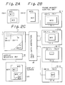
- Figures 2A to 2C are block diagrams showing a multiwindow display control apparatus according to an embodiment of the present invention. Note, throughout the drawings, the same reference numerals and symbols represent the same parts.
- Referring to Figs. 2A to 2C, an explanation is given of an example of realizing a page turning operation in which a first page consists of windows W10, W11, and W12 as shown in Fig. 2A, and a second page consists of windows W20 and W21 as shown in Fig. 2B. These pages are to be overlapped as if they are pages of a book. It is assumed that the background of the overlapping pages is a window W30.
- Assuming that the group number GN of the windows W10, W11, and W12 is "1", the group number GN of the windows W20 and W21 is "2", and the group number GN of the window W30 is "3".
- As shown in Fig. 2C, the pixel data of the respective windows W30 to W21 are stored in the frame memory units 13-i in the respective frame memory control units 12-i (i = 1 to 6). Also, in each frame memory unit, a group number GN and a priority number PN indicating the display priority order in the same group are set. In this embodiment, the larger the priority number PN, the higher the display priority order.
- For example, the windows W10 and W11 have the same group number GN = 1, and therefore, are included in one group of windows having the group number GN = 1. The priority numbers in this group of windows are PN = 1 for the window W10 and PN = 2 for the window W11. If these windows W10 and W11 are to be overlapped, the window W11 is preferentially displayed because it has a higher priority number than the priority number of the window W10. It should be noted that the frame memory control unit corresponding to the window W12 is omitted from Fig. 2, for simplicity.
- In the group number storing
frame memory 11 provided in theoutline generating unit 10 shown in Fig. 1, a group number GN is set for each pixel of the subject to be displayed. In the example shown in Fig. 2C, the group number GN of the background part is assumed to be "3", the group number GN for the first page is assumed to be "1", and the group number GN for the next page is assumed to be "2". Therefore, in accordance with the page turning operation as illustrated by an arrow, the region in which the group number GN is "2" is gradually increased. - The group number storing
frame memory 11 is scanned, as shown in the figure by dotted lines, synchronously with the raster scan on the display, and the group number GN for each pixel is output from theframe memory 11 to the pixeldata arbitration unit 14. - Picture data, a group number GN, and a priority number PN are always output from the frame memory unit 13-i in each frame memory control unit 12-i to the pixel
data arbitration unit 14. - The pixel
data arbitration unit 14 selects pixel data which has the highest priority in the outputs of a frame memory control unit 12-i having a group number GN which coincides with the group number GN from the group number storingframe memory 11, and sends the selected pixel data to thedisplay interface unit 16. - For example, at a scanning time point xa in the group number storing
frame memory 11, since a group number GN = 3 output from theframe memory 11 coincides with the group number output from theoutline generating unit 10, and since the priority of the window W30 is highest at the scanning point xa, pixel data of the window W30 stored in the frame memory unit 13-1 is displayed. - At a scanning time point xb, since a group number GN = 1 is output from the
frame memory 11, pixel data of the corresponding position in the window W10, W11, or W12 is displayed. When an overlapping of these windows occurs, the window thereamong having the largest priority number PN is displayed. - Similarly, at a scanning point xc, a group number GN = 2 is output from the
frame memory 11, and the window W20 or W21 of the second page shown in Fig. 2B is displayed. - Accordingly, by merely setting in the group number storing
frame memory 11, by a processor through thesystem bus 17, the group numbers corresponding to the respective pixels for a page turning operation, for example, the page turning operation and so forth can be simply realized without effecting a change of the contents of the frame memory units 13-i in the frame memory control units 12-i. Namely, according to the present invention, each of the frame memory units 13-i merely fixedly stores data relating to the own window. - Instead of providing the group number storing
frame memory 11 and rewriting the group numbers therein, it is also possible to prepare a plurality of control registers in theoutline generating unit 10, as described later in more detail with reference to Fig. 9. In this case, briefly, the control registers are provided to correspond to the respective group numbers, and addresses of the regions of the group of windows are stored in the control registers. Thus, signals representing individual group number regions, i.e., the group window rectangular region signals of the regions occupied by a group of windows of the respective group numbers, are generated from the control registers and these group window rectangular region signals are used for outputting the group numbers from the outline generator 10 (See Fig. 9). - The pixel
data arbitration unit 14 comprises a plurality of pixel data arbitration circuits 15-i corresponding to the respective frame memory control units 12-i, as shown in Fig. 1. Each of the pixel data arbitration circuits 15-i inputs and outputs a group number signal, a priority number signal, and a pixel data signal. Optionally, each pixel data arbitration circuit 15-i inputs and outputs the group window rectangular region signal. There are two embodiments relating to the connection of these signal lines. Namely, in one embodiment, as shown in Fig. 3A, the pixel data arbitration circuits 15-i are connected by a daisy chain, and in another embodiment, as shown in Fig. 3B, the pixel data arbitration circuits 15-i are connected by a bus. - Also, as a construction of the
outline generating unit 10, there are two embodiments as mentioned before, i.e., one in which the group number storingframe memory 11 is provided, and another in which control registers are provided for generating the group window region signals. - Further, as a display position control of a window, there are two embodiments, i.e., one in which the control is carried out by an absolute coordinate on the display screen, and another in which the control is carried out by a relative coordinate with respect to a region occupied by a group of windows.
- Still further, the pixel data arbitration circuits 15-i, can be constructed by providing calculators of two systems for calculating picture data to output the calculated result (See Fig. 17), and for displaying a cursor and so forth, a pixel data forcible changing mechanism (See Fig. 18) can be provided.
- The present invention can be embodied by combining these various embodiments.
- In the construction of the
outline generating unit 10, a first embodiment is shown in Fig. 8 in which the group number storingframe memory 11 is employed for generating the group number signal indicating the group number corresponding to each group window display region, in a state where a plurality of groups of windows each consisting of a plurality of windows are arbitrarily overlapped and displayed on a display. - A second embodiment is shown in Figs. 9 to Fig. 13 in which the group number signal is generated by setting an address in the control register.
- A third embodiment is shown in Fig. 14 in which the
outline generating unit 10 outputs not only the group number signal but also a group window region signal to be used for a display control by a relative coordinate. - A fourth embodiment is shown in Fig. 15 and Fig. 16 in which the pixel data arbitration units 15-i have a daisy chain structure and pixel data of two systems are exchanged.
- A fifth embodiment is shown in Fig. 17 in which a calculating mechanism of pixel data of two systems is added to the fourth embodiment.
- A sixth embodiment is shown in Fig. 18 in which a pixel data forcible changing mechanism is added to the fourth embodiment or the fifth embodiment.
- A seventh embodiment is shown in Fig. 19 in which the third embodiment of the
outline generating unit 10 and the fourth embodiment of the pixel data arbitration circuit 15-i are combined. - An eighth embodiment is shown in Fig. 20 in which the third embodiment of the
outline generating unit 10 and the fifth embodiment of the pixel data arbitration circuit 15-i are combined. - A ninth embodiment is shown in Fig. 21 in which the third embodiment of the
outline generating unit 10 and the sixth embodiment of the pixel data arbitration circuit 15-i are combined. - A tenth embodiment is shown in Fig. 22 in which the pixel data arbitration circuit 15-i has a bus structure.
- First, examples of the constructions of the frame memory control unit 12-i and the
display interface unit 16, which are common to these embodiments, are explained with reference to Fig. 4 to Fig. 6. (Examples of the constructions of the frame memory control unit 12-i) - Figure 4 shows a construction of the frame memory control unit 12-i according to an embodiment of the present invention.
- The frame memory control unit 12-i comprises a group number register (GNR) 41 for storing a group number GN allocated to the window corresponding to this frame memory control unit, a priority number register (PNR) 42 for storing a priority number allocated to the window, a
display control unit 43, used only when the display is effected by relative coordinates with respect to the group window region on the display screen, for instructing theframe memory unit 13 on the display range and position on the display screen, theframe memory unit 13 for storing pixel data of the window to be displayed on the display, and a display enable regionsignal generating circuit 44, optionally provided, for generating a signal to limit the range actually displayed on the display to an arbitrary shape, in accordance with preset masking data. - Figure 5 shows a block diagram of the
display control unit 43 shown in Fig. 4. Thedisplay control unit 43 in Fig. 5 is used when the display position control is carried out by the relative coordinates with respect to the group window region. - The
display control unit 43 receives a group window region signal GW from the pixeldata arbitration unit 14, and based on the group window region signal GW, a horizontal synchronization signal HS, a vertical synchronization signal VS, a pixel clock signal DCK, and signals DSPX and DSPY indicating the range of the group window region in the X direction and in the Y direction are generated. - To this end, there are provided counters 51-1 and 51-2 for counting the group window region signal GW in response to the pixel clock DCK and the horizontal synchronization signal HS through the AND gates 50-1 and 50-2 respectively. The output of the counter 51-1 is the X coordinate GWX of the group window region, and the output of the counter 51-2 is the Y coordinate GWY of the group window region.
- On the other hand, there are provided a window display start X coordinate
register 53, a window display end X coordinateregister 54, a window display start Y coordinateregister 55, and a window display end Y coordinateregister 56, connected to thesystem bus 17. In each of these registers, a start coordinate or an end coordinate of the window handled by the frame memory control unit 12-i is preset. - These outputs and the outputs of the counters 51-1 and 51-2 are compared by comparators 57-1 to 57-4 respectively. When the value GWX coincides with the X start coordinate in the
register 53, a flip-flop 58-1 is set. Similarly, when the value GWY coincides with the Y start coordinate in theregister 55, a flip-flop 58-2 is set. When the values GWX and GWY coincide with the end coordinates in theregisters - The outputs of the flip-flops 58-1 and 58-2 become the signals DSPX and DSPY indicating the range of the group window region.
- Note, if the display position control of each window is not effected by the relative coordinates, the construction shown in Fig. 5 can be further simplified.
- The
frame memory unit 13 shown in Fig. 4 has a construction as shown in Fig. 6. - In Fig. 6, 61 is a bus interface circuit having an interface with address/data lines and control signal lines in the
system bus 17, and aframe memory 67 is used for storing pixel data and is constructed by a dual port dynamic random access memory (RAM) having random ports and serial ports. - A refresh address/control
signal generating circuit 62 is used for generating an address at the time of a refreshing of theframe memory 67 and control signals relating to the refreshing address. - A serial port address/control
signal generating circuit 63 is a circuit for receiving the signals DSPX and DSPY, from thedisplay control unit 43, indicating the range of the group window region in the X direction and in the Y direction, and for generating an address of a serial port which outputs pixel data from theframe memory 67 and control signals. - A
timing generating circuit 65 is a circuit for generating a refresh timing of the dynamic RAM constituting theframe memory 67, a random port access timing by an external CPU and so forth, and a serial port access timing. Atiming arbitration circuit 66 is a circuit for arbitrating the timing output from thetiming generating circuit 65, and for controlling aselector 64. - A pixel
data multiplexing circuit 68 is used for multiplexing digital pixel data output from several serial ports in accordance with a pixel clock frequency. - Pixel data to be displayed on the window is written into the
frame memory 67 through thesystem bus 17 and thebus interface circuit 61 by processing from an external processor (CPU) and so forth, and pixel data is read from a serial port of theframe memory 67 by the signal generated from the serial port address/controlsignal generating circuit 63, and finally, in response to the pixel clock frequency, pixel data PDn is output from the pixeldata multiplexing circuit 68. - Figure 7 shows a block diagram of the
display interface unit 16 according to an embodiment of the present invention. - The
display interface unit 16 comprises a D/A converter 71, a display synchronizationsignal generating circuit 72, and adisplay driving circuit 73. - The D/
A converter 71 is used for converting a digital signal of the pixel data PD, which is the output of the final stage pixel data arbitration circuit, into an analog signal. The display synchronizationsignal generating circuit 72 is used for preparing a horizontal synchronization signal or a vertical synchronization signal synchronized with a raster scan, and thedisplay driving circuit 73 synthesizes the output of the D/A converter 71 and the output of the display synchronizationsignal preparing circuit 72 to generate a display signal. - Figure 8 shows the first embodiment of the
outline generating unit 10. - In Fig. 8, a
bus interface circuit 81 has an interface with the address/data lines and the control lines in thesystem bus 17, and the group number storingframe memory 11 is constructed by a dual port dynamic RAM having a random port and a serial port. - A refresh address/control
signal generating circuit 82 is used for generating an address of the group number storingframe memory 11 when it is refreshed, and a control signal related to the refreshing address, and a serial port address/controlsignal generating circuit 83 is used for generating an address and a control signal for a serial port from which a group number corresponding to pixel data is output. - A
timing generating circuit 85 is used for generating a refresh timing of the dynamic RAM which constructs the group number storingframe memory 11, a timing of an access of the random port by an external CPU and so forth, and a timing of a serial port access. - A
timing arbitration circuit 86 is used for arbitrating the output timings from thetiming generating circuit 85 to control aselector 84. When the timings are in competition, an arbitration is carried out of the priority order from a serial port access timing, through a refresh timing, to a random port access timing. - A pixel
data multiplexing circuit 87 is used for multiplexing, in accordance with the pixel clock frequency, digital data having a group number GN corresponding to respective pixels output from several serial ports. - Group numbers are written into the group number storing
frame memory 11 through thesystem bus 17 and thebus interface circuit 81 by accessing from an external CPU and so forth, and a group number is read from the serial port of the group number storingframe memory 11, by a signal generated from the serial port address/controlsignal generating circuit 83, and a group number GN for each pixel is finally output by the pixeldata multiplexing circuit 87 in response to the pixel clock frequency. - Note, when the display overlapping relationship of the windows in a window group is to be changed, the data in the group number storing
frame memory 11 is changed. By applying a technique used in an animation display and so forth, however, it is possible to reduce the frame memory capacity and to carry out a high speed control. This technique per se is not directly related to the gist of the present invention, and is not essential for the reduction the rest to practice, and thus a detailed explanation of this technique is omitted here. - As a specific effect in this embodiment, various types of and arbitrary shaped group window regions can be generated, since the writing/updating of the group number into the group number storing
frame memory 11 is carried out by software control by a processor. - By constructing the
outline generating unit 10 as shown in Fig. 9, for example, the group number signals can be generated by hardware instead of generating the group number signals by accessing the group number storingframe memory 11 shown in Fig. 8. - The
outline generating unit 10 shown in Fig. 9 comprises a display enable regionaddress generating unit 91 for generating display addresses in the horizontal direction X and in the vertical direction Y, to be displayed on the display, a group window rectangularregion generating unit 92 for generating rectangular region signals for the respective groupwindows GW# 0,GW# 1,GW# 2, ..., and GW#n by the above-mentioned display addresses X and Y and values set by a processor connected through thesystem bus 17, a specialregion generating unit 93 for generating special group window region signals such as page turning pattern signals, a display priority sortingswitch unit 94 for switching the group window region signals from a higher order of the display priority to a lower order of the display priority, a displaypriority determining unit 95 for determining a group window region signal having the highest priority among the effective plural group window region signals output from the display prioritysorting switching unit 94 to enable the corresponding output signal, and a groupnumber register unit 96 for outputting a group number GN which is set by the processor during the enabling of the signal output from the displaypriority determining unit 95. - The group window region signal is a signal indicating the maximum range which can be occupied by the grouped windows in the group of windows. When the region is a rectangular region GW0 as shown in Fig. 10A, the group window region signal is obtained by synthesizing the X direction signal SX and the Y direction signal SY in accordance with the horizontal synchronization signal and the vertical synchronization signal. The X direction signal SX conforms with the X-direction side of the region GW0, and the Y direction signal SY conforms with the Y-direction side of the region GW0.
- The signals output from the priority sorting
switch unit 94 shown in Fig. 9 are, as shown in Fig. 10B for example, the respective group window region signals GW1 and GW2 arranged in the display priority order. When there is an overlap between the group window regions also represented by GW1 and GW2, the displaypriority determining unit 95 determines, as shown in Fig. 10C, that only the group window region signal having the highest priority is enabled. - The group
number register unit 96 replaces these group window region signals GW1 and GW2 with the group number signals GN1 and GN2, as shown in Fig. 10D, which are the values preset in thegroup number register 96. - Figure 11 shows an example of the construction of the group window rectangular
region generating unit 92 in theoutline generating unit 10. - In Fig. 11, the group window rectangular
region generating unit 92 comprises region generating circuits 110-0 to 110-n corresponding to the respective group windows. These region generating circuits have the same structure having a group window display start X coordinateregister 111, a group window displayend X register 112, a group window display start Y coordinateregister 113, and a group window displayend Y register 114. In these registers, a start coordinate of the upper left and the end coordinate of the lower right of the rectangular region are set by a processor through thesystem bus 17. - A comparator 115-1 compares the X address generated by the display enable region
address generating unit 91 shown in Fig. 9 and the value in the group window display start X coordinateregister 111, and when they coincide, a flip-flop 116-1 is set. When the X address coincides with the value of the group window display end X coordinateregister 112, the flip-flop 116-1 is set. - With respect to the Y direction also, comparators 115-3 and 115-4 control the set/reset of the flip-flop 116-2, and when both the flip-flops 116-1 and 116-2 are set, the group window region signals GW#i (i = 0 to n) are output through an AND
gate 117. - The special
region generating unit 93 shown in Fig. 9 is used for generating a pattern of a special region other than a rectangular region. The special pattern is, for example, that used in the page turning operation when the group window rectangular region signals GW are used for determining the relative coordinates of the windows. The specialregion generating unit 93 has a construction as shown, for example, in Fig. 12. - As shown in Fig. 12, there are provided an
X address counter 120 for counting pixel clocks DCK for each horizontal synchronization signal HS, and aY address counter 121 for counting the horizontal synchronization signals HS for each vertical synchronization signal VS, and further, a change point coordinatememory 123 in which a set of coordinates indicating the boundaries of the group window region (referred to as change point coordinates) for each line are stored. - The value read from the change point coordinate
memory 123 and the output of theX address counter 120 are compared by acomparator 124, and when they coincide, a flip-flop 125 is set. The output of the flip-flop 125 is sent, as is or through aninverter 126 in accordance with a selection by a processor, to the display priority sortingswitch unit 94, and is used as a signal of a group window region having a special shape. - Practically, the special
region generating unit 93 has a construction as shown in Fig. 13. Assuming that the size of the display screen is m dots x n lines. The change point coordinatememory 123 stores several sets which each include X coordinate values from the first line to the n-th line. In the example shown in Fig. 13, sets of the change point coordinates from first frame to γ-th frame can be stored. - For example, when the data in the first frame is selected, and when the data is 1000 for the first line, 970 for the second line, ..., and 200 for the n-th line, then the group window region signals GW are generated in such a way that, in the first line, the group window region starts or ends when the X address becomes 1000, and in the second line, the group window region starts or ends when the X address becomes 970. This is the same for the other lines.
- As a result, a region signal GWi or GWj is generated as shown in Fig. 13.
- In this embodiment, since the change of the region occupied by each group number can be controlled by hardware, a specific effect of a high speed change is obtained.
- When the control of the display position of each window in one group window is effected by a relative coordinate with respect to the region occupied by the group window, the pixel
data arbitration unit 14 and each frame memory control unit 12-i shown in Fig. 1 must know the position of the region occupied by the group window. - To this end, in the third embodiment, as shown in Fig. 14, the output signals of the group window rectangular
region generating unit 92, i.e., the group window region signalsGW# 0,GW# 1,GW# 2, ..., and GW#n, are output to the pixeldata arbitration unit 14 in the multiwindow display control apparatus shown in Fig. 1, and a corresponding one of thesesignals GW# 0,GW# 1,GW# 2, ..., and GW#n is sent to each frame memory control unit 12-i through the pixeldata arbitration unit 14. The circuit construction other than this output function is the same as that of the second embodiment shown in Fig. 9. - The third embodiment has an advantage in that, when the display position of the group window is to be changed, each frame memory control unit 12-i can manage each window by the relative coordinates with respect to the group window region.
- Figure 15 shows an example of the pixel data arbitration circuit 15-n in the pixel
data arbitration unit 14 having the daisy chain structure as shown in Fig. 3A. - The n-th (n = 1, 2, ...) pixel data arbitration circuit 15-n has, as fundamental construction elements, a comparator 151 for detecting a coincidence between the group number GNn-1 from the previous stage pixel data arbitration circuit 15-(n-1) and the group number GNn from the n-th stage frame memory control unit 12-n, a comparator 152 for detecting whether the priority number from the previous stage pixel data arbitration circuit 15-(n-1) is smaller than the priority number GNn from the n-th stage frame memory control unit 12-n, an AND gate 153 having inputs for receiving the outputs of the comparators 151 and 152 and the display enable indication signal DEn from the n-th stage frame memory control unit 12-n, to output a control signal S, and a selector 154 for selecting a A group of the signals from the previous stage pixel data arbitration circuit 15-(n-1) when the control signal S is "L" and for selecting a B group of signals including the group number signal GNn-1 from the previous stage pixel data arbitration circuit 15-(n-1), the priority number signal PNn from the n-th stage frame memory control unit 12-n, and the pixel data PDn from the n-th stage frame memory control unit 12-n when the control signal S is "H".
- The signals of a group number GNn-1 , a priority number PNn-1 , and pixel data PDn-1 output from the n-1 th pixel data arbitration circuit become inputs of the n-th pixel data arbitration circuit 15-n.
- Also, the signals of a group number GNn , a priority number PNn , pixel data PDn , and a display enable indication signal DEn , indicating whether the pixel data PDn is effective or invalid and which are output from the n-th stage frame memory control unit, become inputs of the n-th pixel data arbitration circuit 15-n.
- The
comparator 151 determines whether or not the group numbers GNn-1 and GNn coincide, and thecomparator 152 determines whether or not the priority number PNn is larger than the priority number PNn-1 which has been sent from the previous stage. When these two conditions and a condition of the display enable indication signal DEn are satisfied, the output of the ANDgate 153 becomes "H", and the 2-1selector 154 selects the signal of the B system and outputs it to the (n+1)-th stage pixel data arbitration circuit. As a result, although the group number GN is not changed, the priority number PN and the pixel data PD are changed from those of the (n-1)-th stage to PNn and PDn of the n-th stage. - On the other hand, when the AND of the above-mentioned three conditions is not satisfied, all signals from the (n-1)-th stage are output to the (n+1)-th stage pixel data arbitration circuit of the next stage, without change.
- Next, the principle of the total operation of the multiwindow display control apparatus according to this fourth embodiment of the present invention is described according to Fig. 16.
- In Fig. 16, PD₁ to PD₆ are pixel data, GN₁ to GN₆ are group numbers, PN₁ to PN₆ are priority numbers, CNR is a group number register, PNR is a priority number register, FM is a frame memory unit 13-i for storing pixel data, and DE is a signal indicating validity of the display, i.e., when "1", the display is valid, and when "0", the display is invalid. Note, in Fig. 16, each of the pixel data PD₁ to PD₆ includes four pixels, and the respective pixel data flow serially in synchronization with the pixel clock. To facilitate the processing speed, it is possible to process several pixels as one with parallel data during the process up to the final output.
- The
outline generating unit 10 generates pixel data PD₁ of the background, group numbers GN₁ of "2", "1", "3", and "1" for the respective pixels, and lowest priority numbers PN₁ which are all "0". - At a position (1), the pixel data arbitration circuit 15-1 receives the signals PD₁ , GN₁ , and PN₁ pixel by pixel, finds a coincidence between the group number GN₁ and a value "1" stored in the group number register GNR, and compares the priority number PN₁ corresponding to the pixel data having the group number GN₁ equal to the value in the group number register GNR. In this example, the group numbers of the second and fourth pixels are the same as the value "1" in the group number register GNR. With respect to the second and fourth pixels, since the priority number register PNR in the frame memory control unit 12-1 stores "1", which is larger than the "0" in the priority numbers PN₁ , and the display enable indication DE of the corresponding pixel is valid ("1"), the corresponding pixel data and the priority numbers of the PN₁ output from the
outline generating unit 10 are replaced by the pixel data stored in the frame memory FM and the priority number of "1" in the priority number register PNR in the frame memory control unit 12-1. The replaced pixel data and the priority numbers are then output as pixel data PD₂ and a priority number PN₂ , from the pixel data arbitration circuit 15-1. - At a position (2), the group number of the first pixel coincides with the value "2" in the group number register GNR, and therefore, by a similar comparison, the pixel data and a priority number of the first pixel output from the pixel data arbitration circuit 15-1 are replaced by the pixel data and the priority number in the frame memory control unit 12-2, and thus the pixel data arbitration circuit 15-2 outputs the pixel data PD₃ and the priority numbers PN₃ as illustrated.
- A similar operation is carried out at a position (3).
- At a position (4), since the group number identical to "4" stored in the group number register GNR of the frame memory control unit 12-4 is not included in the group numbers GN₄ output from the
outline generating unit 10, PD₄ and PN₄ are output as PD₅ and PN₅ , without replacement. - At a position (5), the pixels which satisfy the condition that the group numbers are the same as each other and the priority in the PNR in the frame memory control unit 12-5 is larger than the priority number output from the pixel data arbitration circuit 15-4, are the second pixel and the fourth pixel. The display enable indication DE corresponding to the fourth pixel, however, is "0", i.e., invalid, and thus only the second pixel is the subject to be replaced.
- As described above, at each frame memory control unit, pixel data and priority numbers are replaced by the corresponding one of the pixel data arbitration circuit 15-1 to 15-5, and finally, pixel data having a group number which coincides with the group number generated from the
outline generating unit 10, having the largest priority number, and having a display enable indication which indicates a validity of the display, are output and displayed through thedisplay interface unit 16. - A specific effect of this fourth embodiment employing the daisy chain structure is the enabling of a high transfer speed, and a reduction of the number of signal lines by multiplexing, since the transfer distance of signals and the synchronization among the signals are limited to between adjacent boards of the pixel data arbitration circuits. That is, because of the short distance between adjacent boards, and because each board independently performs a synchronization of timing of a receiving signal to transmit it to the next board, the requirement for system design relating to the timing is very loose so that the frequency of the transmitted signal can be made extremely high. Therefore, the signals can be transmitted by multiplexing, resulting in the decrease of the signal lines.
- Figure 17A shows a second example of the pixel data arbitration circuit in the pixel
data arbitration unit 14 having a daisy chain structure. - In Fig. 17A,
reference numeral 177 is a pixel data calculating unit having an A terminal and a B terminal as inputs. When the A terminal is at the "L" level and the B terminal is at the "H" level, the pixeldata calculating unit 177 selects the pixel data PDn output from the n-th stage frame memory control unit 12-n to be output as the pixel data PDn , and when both the A terminal and the B terminal are at the "L" level, the calculatingunit 177 selects the pixel data PDn-1 output from the previous stage pixel data arbitration circuit 15-(n-1) to be output as the pixel data PDn. When the A terminal is at the "H" level and the B terminal is at the "L" level, the calculatingunit 177 becomes a circuit having a raster operation function such as AND, OR, inversion, etc. between the two input data. The kinds of the logical calculation in the raster operation can be instructed from, for example, an external processor not shown in the figure. - Other than the control of the signals of the group number GNn-1 , the priority number PNn-1 , and the pixel data PDn-1 output from the (n-1)-th stage pixel data arbitration circuit 15-(n-1), and the pixel data PDn sent from the n-th stage frame memory control unit 12-n, the pixel data arbitration circuit 15-n shown in Fig. 17 is the same as that of the fourth embodiment explained with reference to Fig. 15. Therefore, an explanation thereof is omitted, and only the portions relating to the pixel data PDn-1 and PDn are explained.
- When the conditions, i.e., the group numbers GNn-1 and GNn are equal, the priority number PNn is larger than the PNn-1 , and the display enable indication DEn is valid, are satisfied, the A terminal of the pixel
data calculating unit 177 becomes "L" and the B terminal becomes "H", through ANDgates data calculating unit 177 selects the signal PDn from the n-th stage frame memory control unit 12-n and outputs it to the (n+1) system, and as a result, the pixel data is replaced from the PDn-1 output from the (n-1)-th stage pixel data arbitration circuit 15-(n-1) to the PDn output from the n-th stage frame memory control unit 12-n. - On the other hand, when the conditions, i.e., the group numbers GNn-1 and GNn are equal, the priority number PNn is equal to the PNn-1 , and the display enable indication DEn is valid, are satisfied, the A terminal of the pixel
data calculating unit 177 becomes "H" and the B terminal becomes "L", through ANDgates data calculating unit 177 performs a predetermined calculation among the pixel data PDn-1 of the (n-1)-th stage and the pixel data PDn of the n-th stage, and outputs the calculated result to the (n+1)-th stage. - When both the A terminal "L" and the B terminal are "L", all signals from the (n-1)-th stage are output without change to the (n+1)-th stage pixel data arbitration circuit.
- Figure 17B shows an example of the pixel
data calculating unit 177 in the circuit shown in Fig. 17A. In Fig. 17B, the pixel data calculating unit 17B includes adistributor 21, a fade-in/fade-out calculatingcircuit 22, a rasteroperation calculating circuit 23, and aswitch 27. The rasteroperation calculating circuit 23 includes, for example, sixteen logic circuits OR, AND, NAND, etc. The fade-in/fade-out calculatingcircuit 22 includes twomultipliers adder 26. Thedistributor 21 receives the priority numbers PDn-1 and PDn and distributes them to the fade-in/fade-out calculatingcircuit 22 and to each logic circuits in the rasteroperation calculating circuit 23. In themultipliers system bus 17. The multiplying coefficients c1 and c2 are between 0 and 1. Theswitch 27 selects, under the control of the processor through thesystem bus 17, one of the outputs from thesystem bus 17, one of the outputs from the fade-in/fade-out circuit 22 and the logic circuits in the rasteroperation calculating circuit 23. - By continuously changing the coefficients c1 and c2, the priority number PDn output from the fade-in/fade-out calculating
circuit 26 is gradually changed. Thus, when theswitch 27 selects the output form the fade-in/ fade-out calculatingcircuit 26, the screen transition of fade in or fade out can be realized. - The sixteen raster operations are as follows.

- This fifth embodiment (5) provides a specific effect in that a screen transition such as fade in, fade out and so forth can be easily realized.
- Figure 18 shows an example of the pixel data arbitration circuit 15-n having a daisy chain structure in the pixel
data arbitration unit 14, in which a pixel data forcible changing mechanism is provided. - In this embodiment, a forcible change instructing register (not shown in the figure) for instructing a forcible change of all of the group number GN, the priority number PN, and the pixel data PD, is newly added to the frame
memory control unit 12 shown in Fig. 4. - When the frame
memory control unit 12 or the pixel data arbitration circuit 15-i is used for displaying a cursor indication or a pop-up menu, for example, preferably the cursor or the pop-up menu can be forcibly displayed at a necessary position without rewriting the group number generated by theoutline generating unit 10. To this end, in this embodiment, there is provided a means for enabling a forcible change of the group number, the priority number, and the pixel data. - The pixel data arbitration circuit 15-n shown in Fig. 18 has, as basic construction elements, a
comparator 181 for detecting a coincidence, acomparator 182 for comparing large and small values, ANDgates 183 and 184, ORgates 185, and twoselectors - When the forcible changing indication register is set to "0", i.e., when the change request signal CGn is "L" and inactive, the operation is almost the same as that of the fourth embodiment described with reference to Fig. 15.
- The operation of the pixel data arbitration circuit 15-n shown in Fig. 18, when the change request signal CGn is at the "L" level, is as follows. The signals of the group number GNn-1 , the priority number PNn-1 , and the pixel data PDn-1 output from the (n-1)-th stage pixel data arbitration circuit 15-(n-1) become the inputs of the n-th stage pixel data arbitration circuit 15-n. Also, the signals of the group number GNn , the priority number PNn , the pixel data PDn , the group number changing request CGn , and the display enable DEn designating valid/invalid of the pixel data PDn become the inputs of the n-th stage pixel data arbitration circuit 15-n.
- The group number GNn-1 and the group number GNn are compared by the
comparator 181 to detect a coincidence, and thecomparator 182 carries out a comparison to determine whether the priority number PNn is larger than the priority number PNn-1 from the previous stage. When the above-mentioned two conditions and the condition that the display enable indication DEn are satisfied, the output of the ANDgate 183 becomes "H" and theselector 186 selects the signals of the priority number PNn and the pixel data PDn of the B system and outputs them to the (n+1)-th stage. As a result, the signals PNn1-1 and the PDn-1 from the (n-1)-th stage are replaced by the PNn and the PDn of the n-th stage. - On the other hand, when the AND of the above-mentioned three conditions cannot be taken, all signals from the (n-1)-th stage are output to the next (n+1)-th stage pixel data arbitration circuit, without change.
- When the signal of the change request CGn is "H", the control signal line S of the two
selectors - In this embodiment, by providing a means for forcibly replacing a group number in the pixel data arbitration circuit 15-n, a specific effect is obtained in that a cursor display or a display of a pop-up menu can be carried out at a high speed.
- Figure 19 shows another example of the pixel data arbitration circuit 15-n having a daisy chain structure in the pixel
data arbitration unit 14; the example of the circuit being used in combination with the third embodiment of theoutline generating unit 10 described with reference to Fig. 14. - The pixel data arbitration circuit 15-n shown in Fig. 19 has a construction in which a
selector 191 for selecting a group window region signal GWn is added to the pixel data arbitration circuit 15-n shown in Fig. 15. - In response to the group number signal GNn output from the group number register in the n-th stage frame memory control unit 12-n, the
selector 191 selects a corresponding group window region signal GWn from the group window region signals GWn-1 in a k-line bus output from the outline generating unit. - The n-th stage frame memory control unit 12-n generates display coordinates of the group window, from the selected group window region signal GWn , and outputs pixel data to the position at which the pixel data is to be displayed. The position is indicated by relative coordinates with reference to the display coordinates.
- According to this embodiment, since the display position of the individual window can be managed by relative coordinates with respect to the display coordinates of the group window, it is not necessary to change the coordinate of the display position of the individual window even when the position of the group window is changed. Therefore, an effect is obtained such that the change of the display of a group window is made easy.
- Figure 20 shows an another example of the pixel data arbitration circuit; the example of the circuit being used in combination with the third embodiment of the
outline generating unit 10 described with reference to Fig. 14. - The pixel data arbitration circuit 15-n shown in Fig. 20 has a construction in which, a
selector 201 for selecting a group window region signal GWn is added to the pixel data arbitration circuit 15-n shown in Fig. 15. - In response to the output GNn from the group number register in the n-th stage frame memory control unit, the
selector 201 selects a corresponding group window region signal GWn from the group window region signals GWn-1 in the k-line bus, output from the outline generating unit. - The n-th stage frame memory control unit generates display coordinates of the group window from the selected group window region signal GWn , and outputs pixel data to the position at which the pixel data is to be displayed. The position is indicated by relative coordinates with reference to the display coordinates.
- According to this embodiment, in addition to the effect of the fifth embodiment, similar to the seventh embodiment, an effect is obtained such that the change of the display of the group window is made easy.
- Figure 21 shows a still further example of the pixel data arbitration circuit 15-n, the example of the circuit being used in combination with the third embodiment of the
outline generating unit 10 described with reference to Fig. 14. - The pixel data arbitration circuit 15-n shown in Fig. 21 has a construction in which a
selector 211 for selecting a group window region signal GWn is added to the pixel data arbitration circuit 15-n shown in Fig. 18. - In response to the output GNn from the group number register in the n-th stage frame memory control unit, the
selector 211 selects a corresponding group window region signal GWn from the group window region signal GWn-1 output from the outline generating unit. - The n-th stage frame memory control unit 12-n generates display coordinates of the group window from the selected group window region signal GWn , and outputs pixel data to the position at which the pixel data is to be displayed. This position is indicated by relative coordinates with reference to the display coordinates.
- According to this embodiment, in addition to the effect of the sixth embodiment, similar to that of the seventh embodiment, an effect is obtained such that the change of the display of the group window is made easy.
- Figure 22A shows a still further example of the pixel data arbitration circuit 15-n having a bus structure in the pixel
data arbitration unit 14. - The pixel data arbitration unit 15-n in this embodiment has, as basic construction elements, two
comparators inverter 223, anNAND gate 224, and two tree-state buffers - The signal lines of the group number GN, the priority number PN, and the pixel data PD constitute a bus structure, and all are connected to the pixel data arbitration circuit 15-n. The group number GN generated by the
outline generating unit 10 is sent through the signal line of the group number GN. - The connection between the priority number PN and each of the pixel data arbitration circuits 15-i and 15-j is as shown in Fig. 22B. For example, when three lines are provided as the signal lines of the priority number PN, the priority is lowest when all are "H", and the priority becomes higher in accordance with an increase in the number of "L" level lines.
- For example, with respect to the three lines of the priority number PN, when the pixel data arbitration circuit 15-i outputs "LHH" to the three lines of the priority number PN, and when the pixel data arbitration circuit 15-j outputs "LLH" to the three lines of the priority number PN, the signal line level becomes "LLH" so that the output of the pixel data arbitration circuit 15-j, which has the highest priority, is enabled.
- The operation of the pixel data arbitration circuit 15-i shown in Fig. 22 is as follows.
- In the n-th stage pixel data arbitration circuit 15-n, the
comparator 221 compares the group number GN generated by theoutline generating unit 10 and the group number GNn output from the n-th stage frame memory control unit 12-n. - When a coincidence is found an output control gate *OE of the three-
state buffer 225 becomes active and the priority number PNn output from the n-th stage frame memory control unit 12-n is output through the three-state buffer 225 to the signal line of the priority number PN in the bus. Simultaneously, the priority number PN is input to one of the inputs of thecomparator 222, where it is determined whether it coincides with the priority number PNn output by the n-th stage frame memory control unit 12-n. If the priority of the signal line of the priority number PN is higher than the priority number PNn output from the n-th stage frame memory control unit 12-n, they do not coincide, and if not, they do coincide. - When the priority number in the bus coincides with the priority number from the frame memory control unit, and when the display enable indication DEn represents that the display is valid, the output control gate *OE of the three-
state buffer 226 is made active so that the pixel data PDn is output to the signal line of the pixel data PD. - In this bus structure system, similar to the fifth embodiment, it is possible to provide a means for calculating pixel data under a specific condition, to thus easily realize a screen transition such as a fade in or fade out. It is also possible for a cursor display and so forth to provide, similar to the sixth embodiment, a means for forcibly replacing the group number.
- In the foregoing embodiments, the descriptions were made in which each frame memory control unit has a responsibility to one window, but according to software control of the known art, it is possible to realize a plurality of windows of the frame memory in each frame memory control unit.
- From the foregoing description, it will be apparent that, according to the present invention, the display priority order among groups of windows is managed by only the outline generating unit; the overlapping display priority in the same group of windows is managed by each frame memory control unit; and the pixel data arbitration unit only compares parameters from the outline generating unit and each frame memory control unit. Thus the functions for synthesizing picture data are treated by separate circuits, and therefore, with respect to display controls associated with a plurality of windows, the display control among groups of windows and the display control within a group of windows can be effected separately, and thus the control becomes very simple.
Claims (29)
- A multiwindow display control method for controlling a display of multiwindows consisting of a plurality of groups of windows each including a plurality of windows, characterized in that:
as parameters for controlling a display of said windows, each of said windows is provided with;
a group number (GN) for identifying a group of windows to which the window belongs; and
a priority number (PN) for indicating a priority of a display in said group of windows;
the display control among said windows being carried out by combining one of said group numbers and one of said priority numbers assigned to each of said windows. - A multiwindow display control method as claimed in claim 1 characterised by
storing pixel data in each of a plurality of frame memory control means (12-i) respectively corresponding to said windows;
storing a first group number (GN) in each of said frame memory control means, said first group number being used for identifying a group of windows to which the window belongs;
storing a priority number (PN) in each of said frame memory control units, said priority number being used for identifying a display priority in the windows included in the same group of windows,
generating a second group number (GN) of a window to be displayed from an outline generating means (10);
determining a group of windows having a first group number (GN) which coincides with said second group number;
determining a window having a highest priority number in the determined group of windows; and
displaying the pixel data of the determined window, said pixel data being read from the frame memory control means which corresponds to the determined window. - A multiwindow display control method as claimed in claim 2, wherein said steps of generating a second group number, of determining a group of windows, of determining a window and of displaying the pixel data, are carried out pixel by pixel.
- A multiwindow display control method as claimed in claim 2 or 3, further comprising, before the step of determining a group of windows, a step of storing a display enable region signal (DEn) in said frame memory control means, said display enable region signal indicating whether or not the display of pixels includes each pixel in each of said windows, said step of determining a window including a step of determining the window to be displayed when said display enable region signal indicates that the display of the pixel data can be made.
- A multiwindow display control method as claimed in any of claims 2 to 4, wherein said step of displaying pixels is carried out by absolute coordinates on a display screen.
- A multiwindow display control method as claimed in any of claims 2 to 5, wherein said step of generating a second group number is carried out group window by group window.
- A multiwindow display control method as claimed in any of claims 2 to 6, further comprising, after said step of storing a priority number, a step of generating a group window region signal (GW) representing the region of each group window when displayed on a display screen, said step of displaying a window is carried out by relative coordinates with respect to said group window region.
- A multiwindow display control method as claimed in claim 7, characterized in that:
a region of each of said group of windows on a display screen is individually determined, and
the display position of each window in each of said group of windows is controlled by relative coordinates with respect to said determined region. - A multiwindow display control apparatus for controlling a display of multiwindows consisting of a plurality of groups of windows each including a plurality of windows, comprising:
plurality of frame memory control means (12-i) each for storing pixel data to be displayed on one of said windows, a first group number of a group of windows to which the window belongs, and a priority number for identifying a display priority in the windows included in the same group of windows;
outline generating means (10) for generating a second group number each identifying one of said group of windows;
pixel data arbitration means (14), operatively connected to said frame memory control means (12-i) and to said outline generating means (10) for determining a group of windows having said first group number (GN) which coincides with said second group number, and for determining a window to be displayed having a priority number of the highest priority in the determined group of windows; and
display means (16), operatively connected to said pixel data arbitration means (14), for displaying pixel data of the determined window. - A multiwindow display control apparatus as claimed in claim 9, wherein said outline generating means (10) comprises a group number storing frame memory (11), said group number being read from said group number storing memory pixel by pixel, and said pixel data arbitration means (14) determines the window to be displayed pixel by pixel.
- A multiwindow display control apparatus as claimed in claim 9 or 10, wherein said pixel data arbitration means (14) comprises a plurality of pixel data arbitration circuits (15-i) respectively connected to said frame memory control means (12-i), said pixel data arbitration circuits (15-i) being connected to each other by a daisy chain structure.
- A multiwindow display control apparatus as claimed in claim 11, wherein each of said pixel data arbitration circuits (15-i) comprises:
first comparing means (151) for detecting a coincidence between said group number (GNn-1) generated from said outline generating means (10) and a group number (GNn) stored in the corresponding frame memory control means (12-n);
second comparing means (152) for detecting whether a priority number (PNn) stored in the corresponding frame memory control means (12-n) is larger than a priority number (PDn-1) sent from the previous stage pixel data arbitration circuit (15-(n-1)); and
selecting means (154) for outputting, when said first comparing means detects the coincidence and said second comparing means detects that the priority number (PNn) stored in the corresponding frame memory control means (12-n) is larger than the priority number (PDn-1) sent from the previous stage pixel data arbitration circuit, the priority number (PNn) and the pixel data (PDn) stored in the corresponding frame memory control means (12-n), and for outputting, when said first comparing means does not detect the coincidence or when said second comparing means detects that the priority number (PNn) stored in the corresponding frame memory control means (12-n) is smaller than the priority number (PDn-1) sent from the previous stage pixel data arbitration circuit, the priority number (PNn-1) and the pixel data (PDn-1) sent from the previous stage pixel data arbitration circuit, said group number (GNn-1) generated from said outline generating means (10) being passed to the next stage pixel data arbitration circuit (15-(n+1)). - A multiwindow display control apparatus as claimed in claim 12, wherein each of said frame memory control means (15-n) stores a display enable signal (DEn) indicating whether or not each pixel is allowed to be displayed, and said selecting means (154) selects said priority number (PNn) and the pixel data (PDn) stored in the corresponding frame memory control means (12-n) to be output to the next stage pixel data arbitration circuit (15-(n+1)) when said display enable signal (DEn) indicates that the pixel is allowed to be displayed.
- A multiwindow display control apparatus as claimed in claim 11, 12 or 13 wherein each of said pixel data arbitration circuits (15-i) comprises:
first comparing means (171) for detecting a coincidence between said group number (GNn-1) generated from said outline generating means (10) and a group number (GNn) stored in the corresponding frame memory control means (12-n);
second comparing means (172) for detecting whether a priority number (PNn) stored in the corresponding frame memory control means (12-n) is larger than a priority number (PDn-1) sent from the previous stage pixel data arbitration circuit (15-(n-1));
selecting means (176) for outputting, when said first comparing means detects a coincidence and said second comparing means detects that the priority number (PNn) stored in the corresponding frame memory control means (12-n) is larger than the priority number (PDn-1) sent from the previous stage pixel data arbitration circuit, the priority number (PNn) in the corresponding frame memory control means (12-n), and for outputting, when said first comparing means does not detect a coincidence or when said second comparing means detects that the priority number (PNn) stored in the corresponding frame memory control means (12-n) is smaller than the priority number (PDn-1) sent from the previous stage pixel data arbitration circuit, the priority number (PNn-1) sent from the previous stage pixel data arbitration circuit;
third comparing means (173) for detecting a coincidence between the priority number (PNn-1) sent from the previous stage pixel data arbitration circuit (15-(n-1)) and the priority number (PNn) stored in the corresponding frame memory control means (12-n); and
pixel data calculating means (177) for outputting, when said first comparing means detects a coincidence and said second comparing means detects that the priority number (PNn) stored in the corresponding frame memory control means (12-n) is larger than the priority number (PDn-1) sent from the previous stage pixel data arbitration circuit, the pixel data (PDn) in the corresponding frame memory control means (12-n); for outputting, when said first comparing means does not detect a coincidence or when said second comparing means detects that the priority number (PNn) stored in the corresponding frame memory control means (12-n) is smaller than the priority number (PDn-1) sent from the previous stage pixel data arbitration circuit, the pixel data (PDn-1) sent from the previous stage pixel data arbitration circuit; and for performing, when said first comparing means and said third comparing means respectively detect the coincidences, a predetermined calculation between said pixel data (PDn-1) sent from the previous stage pixel data arbitration circuit (15-(n-1)) and said pixel data (PDn) in the corresponding frame memory control means (12-n), and for outputting the calculated result;
said group number (GNn-1) generated from said outline generating means (10) being passed to the next stage pixel data arbitration circuit (15-(n+1)). - A multiwindow display control apparatus as claimed in claim 13 or 14, wherein each of said frame memory control means (15-n) stores a display enable signal (DEn) indicating whether or not each pixel is allowed to be displayed;
said selecting means (176) selecting said priority number (PNn) stored in the corresponding frame memory control means (12-n) to be output to the next stage pixel data arbitration circuit (15-(n+1)) when said display enable signal (DEn) indicates that the pixel is allowed to be displayed; and
said pixel data calculating means (177) outputting said pixel data (PDn) stored in the corresponding frame memory control means (15-n) or performing said predetermined calculation when said display enable signal (DEn) indicates that the pixel is allowed to be displayed. - A multiwindow display control apparatus as claimed in any of claims 9 to 15, characterized in that:
each of said pixel data arbitration circuits comprises means (186) for forcibly changing the group numbers, the priority numbers, and the pixel data signals; and
each of said frame memory control units comprises forcible change instructing means (CGn) for instructing the corresponding each pixel data arbitration circuit to forcibly change the signals,
when the forcibly change instructing means outputs an enable signal for a forcible change, all of the group number, the priority number, and the pixel data output from the previous stage pixel data arbitration circuit are forcibly replaced by the group number, the priority number, and the pixel data of the present stage frame memory control unit, and are output to the next stage pixel data arbitration circuit. - A multiwindow display control apparatus as claimed in any of claims 9 to 16, wherein:
each of said frame memory control means (12-i) comprises a forcible change signal generating means for generating a forcible change signal (CGn); and
each of said pixel data arbitration circuits (15-i) comprises:
first comparing means (181) for detecting a coincidence between said group number (GNn-1) generated from said outline generating means (10) and a group number (GNn) stored in the corresponding frame memory control means (12-n);
second comparing means (182) for detecting whether a priority number (PNn) stored in the corresponding frame memory control means (12-n) is larger than a priority number (PDn-1) sent from the previous stage pixel data arbitration circuit (15-(n-1));
first selecting means (187) for outputting, when said forcible change signal (CGn) is active, the group number (GNn) stored in the corresponding frame memory control means (12-n), and for outputting, when said forcible change signal (CGn) is not active, said group number (GNn-1) generated from said outline generating means (10);
second selecting means (186) for outputting, when said forcible change signal (CGn) is active or when said first comparing means detects the coincidence and said second comparing means detects that the priority number (PNn) stored in the corresponding frame memory control means (12-n) is larger than the priority number (PDn-1) sent from the previous stage pixel data arbitration circuit, the priority number (PNn) and the pixel data (PDn) stored in the corresponding frame memory control means (12-n), and for outputting, when said forcible change signal (CGn) is not active and when said first comparing means does not detect a coincidence or when said second comparing means detects that the priority number (PNn) stored in the corresponding frame memory control means (12-n) is smaller than the priority number (PDn-1) sent from the previous stage pixel data arbitration circuit, the priority number (PNn-1) and the pixel data (PDn-1) sent from the previous stage pixel data arbitration circuit. - A multiwindow display control apparatus as claimed in claim 17, wherein each of said frame memory control means (15-n) stores a display enable signal (DEn) indicating whether or not each pixel is allowed to be displayed, and said first selecting means (187) and said second selecting means (186) select said group number (GNn), said priority number (PNn), and the pixel data (PDn) stored in the corresponding frame memory control means (12-n) to be output to the next stage pixel data arbitration circuit (15-(n+1)) when said display enable signal (DEn) indicates that the pixel is allowed to be displayed.
- A multiwindow display control apparatus as claimed in any of claims 9 to 18, wherein said outline generating means (10) comprises:
display enable region address generating means (91);
group window rectangular region generating means (92), operatively connected to said display enable region address generating means (91), for generating group window rectangular region signals (GW#i) of said group of windows (GW);
special region generating means (93) for generating special region signals;
display priority sorting means (94), operatively connected to said group window region rectangular region generating means (92) and to said special region generating means (93), for sorting said group window rectangular region signals according to the desired order of the display priorities of said group of windows;
display priority determining means (95), operatively connected to said display priority sorting means (94), for making only one of said group window rectangular region signals having the highest display priority enabled; and
group number register means (96), operatively connected to said display priority determining means (95), for outputting a desired group number signal (GN) provided to said group window having the highest display priority. - A multiwindow display control apparatus as claimed in claim 19, wherein each of said group window rectangular region generating means (92) comprises:
X start address detecting means (111, 115-1) for detecting an X start address of the corresponding group window;
Y start address detecting means (112, 115-2) for detecting a Y start address of the corresponding group window;
X end address detecting means (113, 115-3) for detecting an X end address of the corresponding group window; and
Y end address detecting means (114, 115-4) for detecting a Y address of the corresponding group window. - A multiwindow display control apparatus as claimed in claim 19 or 20, wherein said special region generating means (93) comprises:
change point coordinate storing memory (123) for storing change points between two of said group of windows to be displayed on the display enable region. - A multiwindow display control apparatus as claimed in claim 19, 20 or 21 wherein said pixel data arbitration means (14) comprises a plurality of pixel data arbitration circuits (15-i) respectively connected to said frame memory control means (12-i), said pixel data arbitration circuits (15-i) being connected to each other by a daisy chain structure.
- A multiwindow display control apparatus as claimed in claim 22, wherein each of said pixel data arbitration circuits (15-i) comprises:
first comparing means (192) for detecting a coincidence between said group number (GNn-1) generated from said outline generating means (10) and a group number (GNn) stored in the corresponding frame memory control means (12-n);
second comparing means (193) for detecting whether a priority number (PNn) stored in the corresponding frame memory control means (12-n) is larger that a priority number (PDn-1) sent from the previous stage pixel data arbitration circuit (15-(n-1));
first selecting means (191) for selecting a group window rectangular region signal (GWn) of the corresponding group of windows (GW) in response to said group number signal (GNn) from the corresponding frame memory control means (12-i), said selected group window rectangular region signal (GWn) being supplied to the corresponding frame memory control means (12-i) for determining the display position of the pixel data by relative coordinates with respect to said group window rectangular region signal; and
second selecting means (208) for outputting, when said first comparing means detects the coincidence and said second comparing means detects that the priority number (PNn) stored in the corresponding frame memory control means (12-n) is larger than the priority number (PDn-1) sent from the previous stage pixel data arbitration circuit, the priority number (PNn) and the pixel data (PDn) stored in the corresponding frame memory control means (12-n), and for outputting, when said first comparing means does not detect a coincidence or when said second comparing means detects that the priority number (PNn) stored in the corresponding frame memory control means (12-n) is smaller than the priority number (PDn-1) sent from the previous stage pixel data arbitration circuit, the priority number (PNn-1) and the pixel data (PDn-1) sent from the previous stage pixel data arbitration circuit, said group number (GNn-1) generated from said outline generating means (10) being passed to the next stage pixel data arbitration circuit (15-(n+1)). - A multiwindow display control apparatus as claimed in claim 22 or 23, wherein each of said frame memory control means (15-n) stores a display enable signal (DEn) indicating whether or not each pixel is allowed to be displayed, and said selecting means (154) selects said priority number (PNn) and the pixel data (PDn) stored in the corresponding frame memory control means (12-n) to be output to the next stage pixel data arbitration circuit (15-(n+1)) when said display enable signal (DEn) indicates that the pixel is allowed to be displayed.
- A multiwindow display control apparatus as claimed in any of claims 9 to 24, wherein each of said pixel data arbitration circuits (15-i) comprises:
first selecting means (201) for selecting a group window rectangular region signal (GWn) of the corresponding group window (GW) in response to said group number signal (GNn) from the corresponding frame memory control means (12-i), said selected group window rectangular region signal (GWn) being supplied to the corresponding frame memory control means (12-i) for determining the display position of the pixel data by relative coordinates with respect to said group window rectangular region signal; and
first comparing means (202) for detecting a coincidence between said group number (GNn-1) generated from said outline generating means (10) and a group number (GNn) stored in the corresponding frame memory control means (12-n);
second comparing means (203) for detecting whether a priority number (PNn) stored in the corresponding frame memory control means (12-n) is larger that a priority number (PDn-1) sent from the previous stage pixel data arbitration circuit (15-(n-1));
second selecting means (208) for outputting, when said first comparing means detects the coincidence and said second comparing means detects that the priority number (PNn) stored in the corresponding frame memory control means (12-n) is larger than the priority number (PDn-1) sent from the previous stage pixel data arbitration circuit, the priority number (PNn) in the corresponding frame memory control means (12-n), and for outputting, when said first comparing means does not detect the coincidence or when said second comparing means detects that the priority number (PNn) stored in the corresponding frame memory control means (12-n) is smaller than the priority number (PDn-1) sent from the previous stage pixel data arbitration circuit, the priority number (PNn-1) sent from the previous stage pixel data arbitration circuit;
third comparing means (204) for detecting a coincidence between the priority number (PNn-1) sent from the previous stage pixel data arbitration circuit (15-(n-1)) and the priority number (PNn) stored in the corresponding frame memory control means (12-n); and
pixel data calculating means (207) for outputting, when said first comparing means detects the coincidence and said second comparing means detects that the priority number (PNn) stored in the corresponding frame memory control means (12-n) is larger than the priority number (PDn-1) sent from the previous stage pixel data arbitration circuit, the pixel data (PDn) in the corresponding frame memory control means (12-n); for outputting, when said first comparing means does not detect the coincidence or when said second comparing means detects that the priority number (PNn) stored in the corresponding frame memory control means (12-n) is smaller than the priority number (PDn-1) sent from the previous stage pixel data arbitration circuit, the pixel data (PDn-1) sent from the previous stage pixel data arbitration circuit; and for performing, when said first comparing means and said third comparing means respectively detect the coincidences, a predetermined calculation between said pixel data (PDn-1) sent from the previous stage pixel data arbitration circuit (15-(n-1)) and said pixel data (PDn) in the corresponding frame memory control means (12-n), and for outputting the calculated result;
said group number (GNn-1) generated from said outline generating means (10) being passed to the next stage pixel data arbitration circuit (15-(n+1)). - A multiwindow display control apparatus as claimed in claim 25, wherein each of said frame memory control means (15-n) stores a display enable signal (DEn) indicating whether or not each pixel is allowed to be displayed;
said second selecting means (208) selecting said priority number (PNn) stored in the corresponding frame memory control means (12-n) to be output to the next stage pixel data arbitration circuit (15-(n+1)) when said display enable signal (DEn) indicates that the pixel is allowed to be displayed; and
said pixel data calculating means (207) outputting said pixel data (PDn) stored in the corresponding frame memory control means (15-n) or performing said predetermined calculation when said display enable signal (DEn) indicates that the pixel is allowed to be displayed. - A multiwindow display control apparatus as claimed in any of claims 9 to 26, wherein:
each of said frame memory control means (12-i) comprises forcible change signal generating means for generating a forcible change signal (CGn); and
each of said pixel data arbitration circuits (15-i) comprises:
first selecting means (211) for selecting a group window rectangular region signal (GWn) of the corresponding group of windows (GW) in response to said group number signal (GNn) from the corresponding frame memory control means (12-i), said selected group window rectangular region signal (GWn) being supplied to the corresponding frame memory control means (12-i) for determining the display position of the pixel data by relative coordinates with respect to said group window rectangular region signal;
first comparing means (212) for detecting a coincidence between said group number (GNn-1) generated from said outline generating means (10) and a group number (GNn) stored in the corresponding frame memory control means (12-n);
second comparing means (213) for detecting whether a priority number (PNn) stored in the corresponding frame memory control means (12-n) is larger than a priority number (PDn-1) sent from the previous stage pixel data arbitration circuit (15-(n-1));
second selecting means (218) for outputting, when said forcible change signal (CGn) is active, the group number (GNn) stored in the corresponding frame memory control means (12-n), and for outputting, when said forcible change signal (CGn) is not active, said group number (GNn-1) generated from said outline generating means (10); and
third selecting means (217) for outputting, when said forcible change signal (CGn) is active or when said first comparing means detects a coincidence and said second comparing means detects that the priority number (PNn) stored in the corresponding frame memory control means (12-n) is larger than the priority number (PDn-1) sent from the previous stage pixel data arbitration circuit, the priority number (PNn) and the pixel data (PDn) stored in the corresponding frame memory control means (12-n), and for outputting, when said forcible change signal (CGn) is not active and when said first comparing means does not detect a coincidence or when said second comparing means detects that the priority number (PNn) stored in the corresponding frame memory control means (12-n) is smaller than the priority number (PDn-1) sent from the previous stage pixel data arbitration circuit, the priority number (PNn-1) and the pixel data (PDn-1) sent from the previous stage pixel data arbitration circuit. - A multiwindow display control apparatus as claimed in claim 27, wherein each of said frame memory control means (15-n) stores a display enable signal (DEn) indicating whether or not each pixel is allowed to be displayed, and said first selecting means (187) and said third selecting means (217) select said group number (GNn), said priority number (PNn), and the pixel data (PDn) stored in the corresponding frame memory control means (12-n) to be output to the next stage pixel data arbitration circuit (15-(n+1)) when said display enable signal (DEn) indicates that the pixel is allowed to be displayed.
- A multiwindow display control apparatus as claimed in any of claims 9 to 28, characterized in that:
said pixel data arbitration unit (14) comprises a plurality of pixel data arbitration circuit (15-i) corresponding to said respective frame memory control unit (12-i),
the connections of at least the group number signal line, the priority number signal line, and the pixel data signal line in the signal lines among the pixel data arbitration circuits, are bus connections among the respective pixel data arbitration circuits.
Applications Claiming Priority (4)
| Application Number | Priority Date | Filing Date | Title |
|---|---|---|---|
| JP161087/90 | 1990-06-19 | ||
| JP16108790 | 1990-06-19 | ||
| JP2245372A JPH0792658B2 (en) | 1990-06-19 | 1990-09-14 | Multi-window display control method and apparatus |
| JP245372/90 | 1990-09-14 |
Publications (3)
| Publication Number | Publication Date |
|---|---|
| EP0462565A2 EP0462565A2 (en) | 1991-12-27 |
| EP0462565A3 EP0462565A3 (en) | 1992-07-22 |
| EP0462565B1 true EP0462565B1 (en) | 1995-12-27 |
Family
ID=26487340
Family Applications (1)
| Application Number | Title | Priority Date | Filing Date |
|---|---|---|---|
| EP91109959A Expired - Lifetime EP0462565B1 (en) | 1990-06-19 | 1991-06-18 | Multiwindow display control method and apparatus |
Country Status (4)
| Country | Link |
|---|---|
| US (1) | US5600346A (en) |
| EP (1) | EP0462565B1 (en) |
| CA (1) | CA2044931C (en) |
| DE (1) | DE69115762T2 (en) |
Families Citing this family (63)
| Publication number | Priority date | Publication date | Assignee | Title |
|---|---|---|---|---|
| JPH077316B2 (en) * | 1991-06-10 | 1995-01-30 | 松下電器産業株式会社 | System restart device |
| US5487145A (en) * | 1993-07-09 | 1996-01-23 | Taligent, Inc. | Method and apparatus for compositing display items which minimizes locked drawing areas |
| JPH08272344A (en) * | 1995-03-29 | 1996-10-18 | Hitachi Ltd | High speed picture display device and method therefor |
| GB2301757B (en) * | 1995-06-01 | 2000-02-02 | Ibm | Graphical user interface |
| US6097388A (en) * | 1995-08-22 | 2000-08-01 | International Business Machines Corporation | Method for managing non-rectangular windows in a raster display |
| US5825359A (en) * | 1995-10-05 | 1998-10-20 | Apple Computer, Inc. | Method and system for improved arbitration of a display screen in a computer system |
| US5856826A (en) * | 1995-10-06 | 1999-01-05 | Apple Computer, Inc. | Method and apparatus for organizing window groups and windows in a table |
| US5838318A (en) * | 1995-11-10 | 1998-11-17 | Intel Corporation | Method and apparatus for automatically and intelligently arranging windows on a display device |
| KR100223628B1 (en) * | 1995-12-20 | 1999-10-15 | 윤종용 | Window processing method and system in image processing system |
| US5995103A (en) * | 1996-05-10 | 1999-11-30 | Apple Computer, Inc. | Window grouping mechanism for creating, manipulating and displaying windows and window groups on a display screen of a computer system |
| US20020080163A1 (en) * | 1998-02-23 | 2002-06-27 | Morey Dale D. | Information retrieval system |
| US6184883B1 (en) * | 1998-03-18 | 2001-02-06 | International Business Machines Corporation | Computer system, program product and method utilizing in-focus switch delay for user interface components |
| US6188398B1 (en) * | 1999-06-02 | 2001-02-13 | Mark Collins-Rector | Targeting advertising using web pages with video |
| US6404443B1 (en) | 1999-08-25 | 2002-06-11 | Sharp Laboratories Of America | Three-dimensional graphical user interface for managing screen objects |
| US6573915B1 (en) * | 1999-12-08 | 2003-06-03 | International Business Machines Corporation | Efficient capture of computer screens |
| JP3906031B2 (en) * | 2001-01-31 | 2007-04-18 | 株式会社東芝 | Moving picture reproducing apparatus and program for causing computer to execute moving picture reproducing process |
| US20060200779A1 (en) * | 2001-04-30 | 2006-09-07 | Taylor Steve D | Cell based end user interface having action cells |
| US7165228B2 (en) * | 2001-04-30 | 2007-01-16 | Broadband Graphics, Llc | Cell based end user interface |
| US7313765B2 (en) * | 2001-04-30 | 2007-12-25 | Broadband Graphics Llc | Cell based EUI methods & apparatuses |
| JP2004164132A (en) * | 2002-11-11 | 2004-06-10 | Nec Corp | Multiwindow display device, multiwindow management method for use therewith, and display control program |
| JP4318913B2 (en) * | 2002-12-26 | 2009-08-26 | 東京エレクトロン株式会社 | Application processing equipment |
| JP2004310655A (en) * | 2003-04-10 | 2004-11-04 | Matsushita Electric Ind Co Ltd | Window stack control method |
| US20050073448A1 (en) * | 2003-10-06 | 2005-04-07 | Buxton Mark J. | Prioritization policy method for selectively compressing image data on a window-by-window basis |
| US20050210416A1 (en) * | 2004-03-16 | 2005-09-22 | Maclaurin Matthew B | Interactive preview of group contents via axial controller |
| US8429059B2 (en) | 2004-06-08 | 2013-04-23 | Rosenthal Collins Group, Llc | Method and system for providing electronic option trading bandwidth reduction and electronic option risk management and assessment for multi-market electronic trading |
| US7555456B2 (en) * | 2004-06-08 | 2009-06-30 | Rosenthal Collins Group, Llc | Method and system for providing electronic information for multi-market electronic trading |
| US7912781B2 (en) * | 2004-06-08 | 2011-03-22 | Rosenthal Collins Group, Llc | Method and system for providing electronic information for risk assessment and management for multi-market electronic trading |
| US20100312718A1 (en) * | 2004-06-08 | 2010-12-09 | Rosenthal Collins Group, L.L.C. | Method and system for providing electronic information for risk assesement and management via net worth for multi-market electronic trading |
| US20110125672A1 (en) * | 2004-06-08 | 2011-05-26 | Rosenthal Collins Group, L.L.C. | Method and system for providing electronic information for risk assesement and management via dynamic total net worth for multi-market electronic trading |
| US20100114753A1 (en) * | 2004-07-12 | 2010-05-06 | Rosenthal Collins Group, L.L.C. | Method and system for automatic commodities futures contract management and delivery balancing |
| US20100076906A1 (en) * | 2004-07-12 | 2010-03-25 | Rosenthal Collins Group, L.L.C. | Method and system for using quantitative analytics on a graphical user interface for electronic trading |
| WO2006017243A2 (en) * | 2004-07-12 | 2006-02-16 | Rosenthal Collins Group, Llc | Method and system for providing a graphical user interface for electronic trading |
| US20080162378A1 (en) * | 2004-07-12 | 2008-07-03 | Rosenthal Collins Group, L.L.C. | Method and system for displaying a current market depth position of an electronic trade on a graphical user interface |
| US7895528B2 (en) * | 2004-08-05 | 2011-02-22 | International Business Machines Corporation | System and method for reversing a windows close action |
| US7620586B2 (en) * | 2004-09-08 | 2009-11-17 | Rosenthal Collins Group, Llc | Method and system for providing automatic execution of trading strategies for electronic trading |
| US20100094777A1 (en) * | 2004-09-08 | 2010-04-15 | Rosenthal Collins Group, Llc. | Method and system for providing automatic execution of risk-controlled synthetic trading entities |
| US8006196B2 (en) * | 2004-09-10 | 2011-08-23 | Presagis | Multi-application graphic display environment |
| FR2877112B3 (en) * | 2004-10-22 | 2007-06-08 | Nds Ltd | METHOD FOR MANAGING DISPLAY WINDOWS |
| US7624064B2 (en) * | 2004-11-01 | 2009-11-24 | Rosenthal Collins Group, Llc | Method and system for providing multiple graphic user interfaces for electronic trading |
| WO2006063016A2 (en) * | 2004-12-09 | 2006-06-15 | Rosenthal Collins Group, Llc | Method and system for providing configurable features for graphical user interfaces for electronic trading |
| US20060248150A1 (en) * | 2005-04-29 | 2006-11-02 | International Business Machines Corporation | Methods and apparatus for managing and distinguishing instant messaging sessions and threads |
| US8589280B2 (en) * | 2005-05-04 | 2013-11-19 | Rosenthal Collins Group, Llc | Method and system for providing automatic execution of gray box strategies for electronic trading |
| US8364575B2 (en) * | 2005-05-04 | 2013-01-29 | Rosenthal Collins Group, Llc | Method and system for providing automatic execution of black box strategies for electronic trading |
| WO2006119272A2 (en) * | 2005-05-04 | 2006-11-09 | Rosenthal Collins Group, Llc | Method and system for providing automatic exeuction of black box strategies for electronic trading |
| US20080288391A1 (en) * | 2005-05-31 | 2008-11-20 | Rosenthal Collins Group, Llc. | Method and system for automatically inputting, monitoring and trading spreads |
| WO2006130650A2 (en) * | 2005-05-31 | 2006-12-07 | Rosenthal Collins Group, Llc | Method and system for electronically inputting, monitoring and trading spreads |
| US7849000B2 (en) * | 2005-11-13 | 2010-12-07 | Rosenthal Collins Group, Llc | Method and system for electronic trading via a yield curve |
| US20110022509A1 (en) * | 2005-11-13 | 2011-01-27 | Rosenthal Collins Group, L.L.C. | Method and system for electronic trading via a yield curve on plural network devices |
| US7734533B2 (en) | 2005-11-13 | 2010-06-08 | Rosenthal Collins Group, Llc | Method and system for electronic trading via a yield curve |
| US20080059846A1 (en) * | 2006-08-31 | 2008-03-06 | Rosenthal Collins Group, L.L.C. | Fault tolerant electronic trading system and method |
| US20100010937A1 (en) * | 2008-04-30 | 2010-01-14 | Rosenthal Collins Group, L.L.C. | Method and system for providing risk assessment management and reporting for multi-market electronic trading |
| US8379058B2 (en) * | 2008-06-06 | 2013-02-19 | Apple Inc. | Methods and apparatuses to arbitrarily transform windows |
| US20120169745A1 (en) * | 2010-12-13 | 2012-07-05 | Collis Quinn Carter | Method and System for Selecting Data for Display in a Plurality of Displays |
| US9747658B2 (en) * | 2013-09-06 | 2017-08-29 | Apple Inc. | Arbitration method for multi-request display pipeline |
| JP2015102567A (en) | 2013-11-21 | 2015-06-04 | 三菱電機株式会社 | Multi-vision display control device and multi-vision system |
| US10575008B2 (en) * | 2015-06-01 | 2020-02-25 | Apple Inc. | Bandwidth management in devices with simultaneous download of multiple data streams |
| JP6843581B2 (en) | 2016-10-24 | 2021-03-17 | キヤノン株式会社 | Image forming device, its control method and program |
| US10999602B2 (en) | 2016-12-23 | 2021-05-04 | Apple Inc. | Sphere projected motion estimation/compensation and mode decision |
| US11259046B2 (en) | 2017-02-15 | 2022-02-22 | Apple Inc. | Processing of equirectangular object data to compensate for distortion by spherical projections |
| US10924747B2 (en) | 2017-02-27 | 2021-02-16 | Apple Inc. | Video coding techniques for multi-view video |
| US11093752B2 (en) | 2017-06-02 | 2021-08-17 | Apple Inc. | Object tracking in multi-view video |
| US10754242B2 (en) | 2017-06-30 | 2020-08-25 | Apple Inc. | Adaptive resolution and projection format in multi-direction video |
| CN110248222B (en) * | 2018-11-21 | 2023-03-17 | 浙江大华技术股份有限公司 | Method, device and system for synchronously displaying multiple windows |
Citations (1)
| Publication number | Priority date | Publication date | Assignee | Title |
|---|---|---|---|---|
| EP0349455A2 (en) * | 1988-06-30 | 1990-01-03 | International Business Machines Corporation | Method for controlling the presentation of nested overlays |
Family Cites Families (8)
| Publication number | Priority date | Publication date | Assignee | Title |
|---|---|---|---|---|
| GB2126054A (en) * | 1982-08-11 | 1984-03-14 | Philips Electronic Associated | Display system with nested information display |
| US4723209A (en) * | 1984-08-30 | 1988-02-02 | International Business Machines Corp. | Flow attribute for text objects |
| US4688167A (en) * | 1984-09-27 | 1987-08-18 | Wang Laboratories, Inc. | Screen manager for data processing system |
| GB2191917A (en) * | 1986-06-16 | 1987-12-23 | Ibm | A multiple window display system |
| JPH0814785B2 (en) * | 1986-09-24 | 1996-02-14 | 株式会社日立製作所 | Display controller |
| JPS6459426A (en) * | 1987-08-31 | 1989-03-07 | Toshiba Corp | Bit map display device |
| US5241656A (en) * | 1989-02-06 | 1993-08-31 | International Business Machines Corporation | Depth buffer clipping for window management |
| US5191644A (en) * | 1990-10-10 | 1993-03-02 | Fuji Xerox Co., Ltd. | Multiwindow control system |
-
1991
- 1991-06-18 DE DE69115762T patent/DE69115762T2/en not_active Expired - Fee Related
- 1991-06-18 EP EP91109959A patent/EP0462565B1/en not_active Expired - Lifetime
- 1991-06-18 CA CA002044931A patent/CA2044931C/en not_active Expired - Fee Related
- 1991-06-19 US US07/717,904 patent/US5600346A/en not_active Expired - Fee Related
Patent Citations (1)
| Publication number | Priority date | Publication date | Assignee | Title |
|---|---|---|---|---|
| EP0349455A2 (en) * | 1988-06-30 | 1990-01-03 | International Business Machines Corporation | Method for controlling the presentation of nested overlays |
Also Published As
| Publication number | Publication date |
|---|---|
| DE69115762T2 (en) | 1996-06-13 |
| DE69115762D1 (en) | 1996-02-08 |
| US5600346A (en) | 1997-02-04 |
| CA2044931A1 (en) | 1991-12-20 |
| CA2044931C (en) | 2000-08-01 |
| EP0462565A2 (en) | 1991-12-27 |
| EP0462565A3 (en) | 1992-07-22 |
Similar Documents
| Publication | Publication Date | Title |
|---|---|---|
| EP0462565B1 (en) | Multiwindow display control method and apparatus | |
| US4070710A (en) | Raster scan display apparatus for dynamically viewing image elements stored in a random access memory array | |
| US4197590A (en) | Method for dynamically viewing image elements stored in a random access memory array | |
| USRE31200E (en) | Raster scan display apparatus for dynamically viewing image elements stored in a random access memory array | |
| EP0995154B1 (en) | Virtual address access to tiled surfaces | |
| US4491834A (en) | Display controlling apparatus | |
| US4094000A (en) | Graphics display unit | |
| US6181353B1 (en) | On-screen display device using horizontal scan line memories | |
| US6529198B1 (en) | Parallel rendering device | |
| JPH04106593A (en) | Still image display device | |
| JPH09245179A (en) | Computer graphic device | |
| EP0241655B1 (en) | Extended raster operating in a display system | |
| US5321805A (en) | Raster graphics engine for producing graphics on a display | |
| JPH08202524A (en) | Graphic display scrolling device | |
| JPS642955B2 (en) | ||
| EP0018759B1 (en) | Raster scanned character display apparatus with divided screen | |
| JPH0383097A (en) | Address generator for vertical scroll | |
| JP3260913B2 (en) | Image playback device | |
| JPH0695959A (en) | Information processor | |
| JPH0792658B2 (en) | Multi-window display control method and apparatus | |
| JP3322109B2 (en) | Display control device | |
| JP2002258827A (en) | Image display device | |
| EP0242139A2 (en) | Display controller | |
| JPS62109182A (en) | High-speed drawing system for straight line | |
| JP2735072B2 (en) | Image display control device and electronic device having the same |
Legal Events
| Date | Code | Title | Description |
|---|---|---|---|
| PUAI | Public reference made under article 153(3) epc to a published international application that has entered the european phase |
Free format text: ORIGINAL CODE: 0009012 |
|
| AK | Designated contracting states |
Kind code of ref document: A2 Designated state(s): DE FR GB |
|
| PUAL | Search report despatched |
Free format text: ORIGINAL CODE: 0009013 |
|
| AK | Designated contracting states |
Kind code of ref document: A3 Designated state(s): DE FR GB |
|
| 17P | Request for examination filed |
Effective date: 19930111 |
|
| 17Q | First examination report despatched |
Effective date: 19940817 |
|
| GRAA | (expected) grant |
Free format text: ORIGINAL CODE: 0009210 |
|
| AK | Designated contracting states |
Kind code of ref document: B1 Designated state(s): DE FR GB |
|
| REF | Corresponds to: |
Ref document number: 69115762 Country of ref document: DE Date of ref document: 19960208 |
|
| ET | Fr: translation filed | ||
| PLBE | No opposition filed within time limit |
Free format text: ORIGINAL CODE: 0009261 |
|
| STAA | Information on the status of an ep patent application or granted ep patent |
Free format text: STATUS: NO OPPOSITION FILED WITHIN TIME LIMIT |
|
| 26N | No opposition filed | ||
| REG | Reference to a national code |
Ref country code: GB Ref legal event code: IF02 |
|
| PGFP | Annual fee paid to national office [announced via postgrant information from national office to epo] |
Ref country code: FR Payment date: 20020610 Year of fee payment: 12 |
|
| PGFP | Annual fee paid to national office [announced via postgrant information from national office to epo] |
Ref country code: GB Payment date: 20020612 Year of fee payment: 12 |
|
| PGFP | Annual fee paid to national office [announced via postgrant information from national office to epo] |
Ref country code: DE Payment date: 20020626 Year of fee payment: 12 |
|
| PG25 | Lapsed in a contracting state [announced via postgrant information from national office to epo] |
Ref country code: GB Free format text: LAPSE BECAUSE OF NON-PAYMENT OF DUE FEES Effective date: 20030618 |
|
| PG25 | Lapsed in a contracting state [announced via postgrant information from national office to epo] |
Ref country code: DE Free format text: LAPSE BECAUSE OF NON-PAYMENT OF DUE FEES Effective date: 20040101 |
|
| GBPC | Gb: european patent ceased through non-payment of renewal fee |
Effective date: 20030618 |
|
| PG25 | Lapsed in a contracting state [announced via postgrant information from national office to epo] |
Ref country code: FR Free format text: LAPSE BECAUSE OF NON-PAYMENT OF DUE FEES Effective date: 20040227 |
|
| REG | Reference to a national code |
Ref country code: FR Ref legal event code: ST |