EP0462272B1 - Method of producing a nonwoven fibrous textured panel and panel produced thereby - Google Patents
Method of producing a nonwoven fibrous textured panel and panel produced thereby Download PDFInfo
- Publication number
- EP0462272B1 EP0462272B1 EP91904310A EP91904310A EP0462272B1 EP 0462272 B1 EP0462272 B1 EP 0462272B1 EP 91904310 A EP91904310 A EP 91904310A EP 91904310 A EP91904310 A EP 91904310A EP 0462272 B1 EP0462272 B1 EP 0462272B1
- Authority
- EP
- European Patent Office
- Prior art keywords
- fibers
- thermoplastic fibers
- web
- thermoplastic
- panel
- Prior art date
- Legal status (The legal status is an assumption and is not a legal conclusion. Google has not performed a legal analysis and makes no representation as to the accuracy of the status listed.)
- Expired - Lifetime
Links
- 238000000034 method Methods 0.000 title claims abstract description 25
- 239000000835 fiber Substances 0.000 claims abstract description 139
- 229920001169 thermoplastic Polymers 0.000 claims abstract description 74
- 239000004416 thermosoftening plastic Substances 0.000 claims abstract description 74
- 239000012530 fluid Substances 0.000 claims abstract description 26
- 238000004519 manufacturing process Methods 0.000 claims abstract description 8
- -1 polyethylene Polymers 0.000 claims description 23
- 239000004698 Polyethylene Substances 0.000 claims description 10
- 239000004743 Polypropylene Substances 0.000 claims description 10
- 238000002844 melting Methods 0.000 claims description 10
- 230000008018 melting Effects 0.000 claims description 10
- 229920000573 polyethylene Polymers 0.000 claims description 10
- 229920001155 polypropylene Polymers 0.000 claims description 10
- 229920000728 polyester Polymers 0.000 claims description 9
- 239000000463 material Substances 0.000 claims description 6
- 229920001778 nylon Polymers 0.000 claims description 6
- 229920002480 polybenzimidazole Polymers 0.000 claims description 6
- 229920000742 Cotton Polymers 0.000 claims description 5
- 229920006282 Phenolic fiber Polymers 0.000 claims description 5
- 210000002268 wool Anatomy 0.000 claims description 5
- 239000004734 Polyphenylene sulfide Substances 0.000 claims description 4
- 229920001617 Vinyon Polymers 0.000 claims description 4
- 229920000069 polyphenylene sulfide Polymers 0.000 claims description 4
- OKTJSMMVPCPJKN-UHFFFAOYSA-N Carbon Chemical compound [C] OKTJSMMVPCPJKN-UHFFFAOYSA-N 0.000 claims description 3
- 239000004696 Poly ether ether ketone Substances 0.000 claims description 3
- 229920000297 Rayon Polymers 0.000 claims description 3
- 229920003235 aromatic polyamide Polymers 0.000 claims description 3
- 229910052799 carbon Inorganic materials 0.000 claims description 3
- 239000011521 glass Substances 0.000 claims description 3
- 229920006393 polyether sulfone Polymers 0.000 claims description 3
- 229920002530 polyetherether ketone Polymers 0.000 claims description 3
- 239000002964 rayon Substances 0.000 claims description 3
- 230000005012 migration Effects 0.000 claims description 2
- 238000013508 migration Methods 0.000 claims description 2
- 229920006397 acrylic thermoplastic Polymers 0.000 claims 2
- 229920003229 poly(methyl methacrylate) Polymers 0.000 claims 2
- ISXSCDLOGDJUNJ-UHFFFAOYSA-N tert-butyl prop-2-enoate Chemical compound CC(C)(C)OC(=O)C=C ISXSCDLOGDJUNJ-UHFFFAOYSA-N 0.000 claims 2
- 239000004744 fabric Substances 0.000 description 9
- 239000004745 nonwoven fabric Substances 0.000 description 9
- 238000010586 diagram Methods 0.000 description 7
- 239000004816 latex Substances 0.000 description 6
- 229920000126 latex Polymers 0.000 description 6
- 238000001816 cooling Methods 0.000 description 5
- 238000009732 tufting Methods 0.000 description 5
- ATUOYWHBWRKTHZ-UHFFFAOYSA-N Propane Chemical compound CCC ATUOYWHBWRKTHZ-UHFFFAOYSA-N 0.000 description 4
- 239000000126 substance Substances 0.000 description 4
- 239000004952 Polyamide Substances 0.000 description 3
- 239000004760 aramid Substances 0.000 description 3
- DQXBYHZEEUGOBF-UHFFFAOYSA-N but-3-enoic acid;ethene Chemical compound C=C.OC(=O)CC=C DQXBYHZEEUGOBF-UHFFFAOYSA-N 0.000 description 3
- 150000001875 compounds Chemical class 0.000 description 3
- 239000005038 ethylene vinyl acetate Substances 0.000 description 3
- 238000010438 heat treatment Methods 0.000 description 3
- 239000007788 liquid Substances 0.000 description 3
- 239000002184 metal Substances 0.000 description 3
- 239000000203 mixture Substances 0.000 description 3
- 229920001200 poly(ethylene-vinyl acetate) Polymers 0.000 description 3
- 229920002647 polyamide Polymers 0.000 description 3
- 239000000047 product Substances 0.000 description 3
- JOYRKODLDBILNP-UHFFFAOYSA-N Ethyl urethane Chemical compound CCOC(N)=O JOYRKODLDBILNP-UHFFFAOYSA-N 0.000 description 2
- 239000004677 Nylon Substances 0.000 description 2
- 239000004693 Polybenzimidazole Substances 0.000 description 2
- 241000555745 Sciuridae Species 0.000 description 2
- WNLRTRBMVRJNCN-UHFFFAOYSA-N adipic acid Chemical compound OC(=O)CCCCC(O)=O WNLRTRBMVRJNCN-UHFFFAOYSA-N 0.000 description 2
- 229920006231 aramid fiber Polymers 0.000 description 2
- JBKVHLHDHHXQEQ-UHFFFAOYSA-N epsilon-caprolactam Chemical compound O=C1CCCCCN1 JBKVHLHDHHXQEQ-UHFFFAOYSA-N 0.000 description 2
- 239000003517 fume Substances 0.000 description 2
- 230000004927 fusion Effects 0.000 description 2
- NAQMVNRVTILPCV-UHFFFAOYSA-N hexane-1,6-diamine Chemical compound NCCCCCCN NAQMVNRVTILPCV-UHFFFAOYSA-N 0.000 description 2
- 239000000155 melt Substances 0.000 description 2
- 229920000642 polymer Polymers 0.000 description 2
- 239000001294 propane Substances 0.000 description 2
- 230000003134 recirculating effect Effects 0.000 description 2
- 229920013683 Celanese Polymers 0.000 description 1
- 240000000491 Corchorus aestuans Species 0.000 description 1
- 235000011777 Corchorus aestuans Nutrition 0.000 description 1
- 235000010862 Corchorus capsularis Nutrition 0.000 description 1
- 229920000271 Kevlar® Polymers 0.000 description 1
- 229920000784 Nomex Polymers 0.000 description 1
- 229920002292 Nylon 6 Polymers 0.000 description 1
- 229920002302 Nylon 6,6 Polymers 0.000 description 1
- 239000004695 Polyether sulfone Substances 0.000 description 1
- 229920013632 Ryton Polymers 0.000 description 1
- 239000004736 Ryton® Substances 0.000 description 1
- BZHJMEDXRYGGRV-UHFFFAOYSA-N Vinyl chloride Chemical group ClC=C BZHJMEDXRYGGRV-UHFFFAOYSA-N 0.000 description 1
- NIXOWILDQLNWCW-UHFFFAOYSA-N acrylic acid group Chemical group C(C=C)(=O)O NIXOWILDQLNWCW-UHFFFAOYSA-N 0.000 description 1
- 235000011037 adipic acid Nutrition 0.000 description 1
- 239000001361 adipic acid Substances 0.000 description 1
- 125000003368 amide group Chemical group 0.000 description 1
- 150000001408 amides Chemical class 0.000 description 1
- 125000003118 aryl group Chemical group 0.000 description 1
- 125000003785 benzimidazolyl group Chemical group N1=C(NC2=C1C=CC=C2)* 0.000 description 1
- 230000015572 biosynthetic process Effects 0.000 description 1
- 230000001427 coherent effect Effects 0.000 description 1
- 230000006835 compression Effects 0.000 description 1
- 238000007906 compression Methods 0.000 description 1
- 239000007859 condensation product Substances 0.000 description 1
- 239000007789 gas Substances 0.000 description 1
- 230000005484 gravity Effects 0.000 description 1
- 239000004761 kevlar Substances 0.000 description 1
- 229910001092 metal group alloy Inorganic materials 0.000 description 1
- 238000002156 mixing Methods 0.000 description 1
- 238000012986 modification Methods 0.000 description 1
- 230000004048 modification Effects 0.000 description 1
- 210000000050 mohair Anatomy 0.000 description 1
- 239000004763 nomex Substances 0.000 description 1
- 229920003986 novolac Polymers 0.000 description 1
- 238000000059 patterning Methods 0.000 description 1
- 239000003208 petroleum Substances 0.000 description 1
- 229920000889 poly(m-phenylene isophthalamide) Polymers 0.000 description 1
- 229920003366 poly(p-phenylene terephthalamide) Polymers 0.000 description 1
- 238000006068 polycondensation reaction Methods 0.000 description 1
- 229920005594 polymer fiber Polymers 0.000 description 1
- 229920000098 polyolefin Polymers 0.000 description 1
- 238000009958 sewing Methods 0.000 description 1
- 229920001059 synthetic polymer Polymers 0.000 description 1
- 229920002803 thermoplastic polyurethane Polymers 0.000 description 1
- XLYOFNOQVPJJNP-UHFFFAOYSA-N water Substances O XLYOFNOQVPJJNP-UHFFFAOYSA-N 0.000 description 1
- 238000004804 winding Methods 0.000 description 1
Images


Classifications
-
- D—TEXTILES; PAPER
- D04—BRAIDING; LACE-MAKING; KNITTING; TRIMMINGS; NON-WOVEN FABRICS
- D04H—MAKING TEXTILE FABRICS, e.g. FROM FIBRES OR FILAMENTARY MATERIAL; FABRICS MADE BY SUCH PROCESSES OR APPARATUS, e.g. FELTS, NON-WOVEN FABRICS; COTTON-WOOL; WADDING ; NON-WOVEN FABRICS FROM STAPLE FIBRES, FILAMENTS OR YARNS, BONDED WITH AT LEAST ONE WEB-LIKE MATERIAL DURING THEIR CONSOLIDATION
- D04H1/00—Non-woven fabrics formed wholly or mainly of staple fibres or like relatively short fibres
- D04H1/40—Non-woven fabrics formed wholly or mainly of staple fibres or like relatively short fibres from fleeces or layers composed of fibres without existing or potential cohesive properties
- D04H1/54—Non-woven fabrics formed wholly or mainly of staple fibres or like relatively short fibres from fleeces or layers composed of fibres without existing or potential cohesive properties by welding together the fibres, e.g. by partially melting or dissolving
-
- D—TEXTILES; PAPER
- D04—BRAIDING; LACE-MAKING; KNITTING; TRIMMINGS; NON-WOVEN FABRICS
- D04H—MAKING TEXTILE FABRICS, e.g. FROM FIBRES OR FILAMENTARY MATERIAL; FABRICS MADE BY SUCH PROCESSES OR APPARATUS, e.g. FELTS, NON-WOVEN FABRICS; COTTON-WOOL; WADDING ; NON-WOVEN FABRICS FROM STAPLE FIBRES, FILAMENTS OR YARNS, BONDED WITH AT LEAST ONE WEB-LIKE MATERIAL DURING THEIR CONSOLIDATION
- D04H1/00—Non-woven fabrics formed wholly or mainly of staple fibres or like relatively short fibres
- D04H1/40—Non-woven fabrics formed wholly or mainly of staple fibres or like relatively short fibres from fleeces or layers composed of fibres without existing or potential cohesive properties
- D04H1/44—Non-woven fabrics formed wholly or mainly of staple fibres or like relatively short fibres from fleeces or layers composed of fibres without existing or potential cohesive properties the fleeces or layers being consolidated by mechanical means, e.g. by rolling
- D04H1/45—Non-woven fabrics formed wholly or mainly of staple fibres or like relatively short fibres from fleeces or layers composed of fibres without existing or potential cohesive properties the fleeces or layers being consolidated by mechanical means, e.g. by rolling by forming intermeshing loops or stitches from some of the fibres
-
- D—TEXTILES; PAPER
- D04—BRAIDING; LACE-MAKING; KNITTING; TRIMMINGS; NON-WOVEN FABRICS
- D04H—MAKING TEXTILE FABRICS, e.g. FROM FIBRES OR FILAMENTARY MATERIAL; FABRICS MADE BY SUCH PROCESSES OR APPARATUS, e.g. FELTS, NON-WOVEN FABRICS; COTTON-WOOL; WADDING ; NON-WOVEN FABRICS FROM STAPLE FIBRES, FILAMENTS OR YARNS, BONDED WITH AT LEAST ONE WEB-LIKE MATERIAL DURING THEIR CONSOLIDATION
- D04H1/00—Non-woven fabrics formed wholly or mainly of staple fibres or like relatively short fibres
- D04H1/40—Non-woven fabrics formed wholly or mainly of staple fibres or like relatively short fibres from fleeces or layers composed of fibres without existing or potential cohesive properties
- D04H1/44—Non-woven fabrics formed wholly or mainly of staple fibres or like relatively short fibres from fleeces or layers composed of fibres without existing or potential cohesive properties the fleeces or layers being consolidated by mechanical means, e.g. by rolling
- D04H1/46—Non-woven fabrics formed wholly or mainly of staple fibres or like relatively short fibres from fleeces or layers composed of fibres without existing or potential cohesive properties the fleeces or layers being consolidated by mechanical means, e.g. by rolling by needling or like operations to cause entanglement of fibres
-
- Y—GENERAL TAGGING OF NEW TECHNOLOGICAL DEVELOPMENTS; GENERAL TAGGING OF CROSS-SECTIONAL TECHNOLOGIES SPANNING OVER SEVERAL SECTIONS OF THE IPC; TECHNICAL SUBJECTS COVERED BY FORMER USPC CROSS-REFERENCE ART COLLECTIONS [XRACs] AND DIGESTS
- Y10—TECHNICAL SUBJECTS COVERED BY FORMER USPC
- Y10T—TECHNICAL SUBJECTS COVERED BY FORMER US CLASSIFICATION
- Y10T428/00—Stock material or miscellaneous articles
- Y10T428/23907—Pile or nap type surface or component
- Y10T428/23979—Particular backing structure or composition
Definitions
- this invention relates to methods of producing nonwoven fibrous panels having a textured outer surface as well as fibrous panels produced by such methods. More particularly, this invention relates to a method for producing a nonwoven fibrous, flexible panel having a textured outer surface that includes needlepunching a needled web of at least interengaged first fibers and second thermoplastic fibers to produce the textured outer surface; and passing a fluid, at a temperature sufficient to melt at least a portion of the second thermoplastic fibers, through the web in a direction from the textured outer surface to produce a plurality of weld joints of the melted fibers; and it relates to nonwoven fibrous panels produced by such methods.
- nonwoven fabric interior linings and floor mats for motor vehicles made up of nonwoven fabrics having tufted surfaces to which a sintered thermoplastic, latex, latex compound, or flexible urethane resin layer must be applied to prevent fraying and to secure the tufts in place
- Wishman U.S. Patent No. 4,320,167
- the FIG. 6 embodiment of Benedyk U.S. Patent No. 4,258,094
- Walters et al. U.S. Patent No. 4,581,272
- DiGioia et al. U.S. Patent No. 4,016,318
- Hartmann et al. U.S. Patent No. 4,169,176
- Tufting is the drawing of yarns through a fabric, either woven or nonwoven, using a tufting machine.
- Tufting machines ire generally multineedle sewing machines which push the yarns through a primary backing fabric that holds the yarns in place to form loops as the needles are withdrawn. Tufting requires that yarns separate from the woven or nonwoven backing fabric be used to form the tufts; thus, tufting of nonwoven fabrics to produce interior linings and floor mats adds costs to manufacture such items.
- the nonwoven staple polymer fiber batt of Street (as above '562), also known as a high-loft nonwoven fabric, is simultaneously compressed substantially by vacuum and heated by pulling air at a temperature that will only make the polyester soft and tacky, through the batt.
- FIGS. 2 and 9 of Street ('562) illustrate the change in thickness and density of the batt before and after the disclosed Street process has been performed on the batt.
- Such substantial batt compression is undesirable in the fabrication of nonwoven fabric interior linings and floor mats, or the like, which generally have a decorative outer surface and must have sufficient strength and thickness to withstand frequent and harsh use.
- US-A-4258094 there is disclosed a melt bonded fabric produced by blending particular ethylene-vinyl acetate fibers with fibers of higher melting materials suitable for use as carpeting (see Abstract).
- the fabric may be built on a scrim comprising any of the conventional woven or nonwoven types including jute, burlap, and woven and nonwoven polymeric fiber webs.
- a conventional lapper is used to deposit a uniform web or batt of garnetted staple fibers on the upper or face surface of scrim.
- the fibers may comprise ethylene-vinyl acetate in staple length of about 1 to about 4 inches or may comprise a mixture of staple fibers of ethylene-vinyl acetate with staple fibers of other compositions including nylon, polypropylene and the like.
- the scrim carrying the web or batt is then passed through a needle loom such as the standard pile loom, which needle loom bonds the fiber layer to the scrim to form a fabric subface.
- the subface may optionally be subjected to a second, or texture needling operation using a texturing loom.
- the patterning or arrangement of needles on the texturing loom can be varied to produce a patterned pile surface having the appearance of conventional tufted or woven carpet (see column 4, lines 42-66).
- the formed pile fabric is passed through melt- bonding means, which may comprise one or more pairs of fusion rollers or may comprise a pair of closely spaced endless belts.
- thermoplastic fibers melt only in the vicinity of the melt bonding means, i.e. the one or more pairs of fusion rollers or the pair of closely spaced endless belts.
- the invention includes a method for producing a nonwoven fibrous, flexible panel having a textured outer surface, comprising the steps of providing a needled web having a back surface, the needled web comprised of interengaged first fibers and second thermoplastic fibers, needlepunching the web to produce the textured outer surface comprising at least a portion of the first fibers and the second thermoplastic fibers, the back surface located opposite the textured outer surface, and passing a fluid, at a temperature sufficient to melt at least a portion of the second thermoplastic fibers, through the web in a direction from the textured outer surface toward the back surface so as to cause migration of said melted second thermoplastic fibers towards said back surface and to produce a plurality of weld joints of said melted second thermoplastic fibers which bind together at least a portion of said first fibers towards said back surface, the textured outer surface thereafter being substantially free of the second thermoplastic fibers.
- a nonwoven fibrous, flexible panel comprising a needled web having a textured front outer surface and a back surface disposed opposite thereof and including interengaged first fibers and second thermoplastic fibers which have been at least partially melted, said outer textured surface being substantially free of said second thermoplastic fibers and said web having a plurality of weld joints formed by said melted second thermoplastic fibers and which bind together at least a portion of said first fibers proximate said back surface.
- a preferred nonwoven needled web of the invention is a blend of at least a first and second type of loose fiber interengaged and consolidated together to form a coherent nonwoven fabric, the second fiber type being a thermoplastic fiber.
- the interengaging and consolidating may be accomplished by an operation known in the art as needlepunching on a needle loom having needles that punch into and withdraw from the webbing at a desired number of strokes per minute; see Adams et al. (U.S. Patent No. 4,424,250) for a more detailed description of needlepunching.
- thermoplastic fibers are available for use as the second thermoplastic type of fiber in the preferred nonwoven needled web; these include, but are not limited to, polyethylene, polypropylene, polyester, nylon, polyphenylene sulfide, polyether sulfone, polyether-ether ketone, vinyon, and bicomponent thermoplastic fibers.
- Nylon fibers as defined by the U.S. Federal Trade Commission, are made from a manufactured substance which is any long chain synthetic polyamide having recurring amide groups (-NH-CO-) as an integral part of the polymer chain; and include those nylon fibers derived from the polyamide condensation product of hexamethylenediamine and adipic acid (i.e.
- Nylon 6,6 Nylon 6,6
- epsilon caprolactam i.e. Nylon 6
- the Phillips Petroleum Company manufactures and sells a suitable polyphenylene sulfide under the trademark "Ryton".
- Vinyon fibers have been defined as fibers made from a manufactured substance which is any long chain synthetic polymer composed of at least 85% by weight of vinyl chloride units.
- An example of a usable bicomponent thermoplastic fiber is one made of a polypropylene core and a polyethylene sheath.
- Chisso Corporation of Japan manufactures a suitable bicomponent polyolefin fiber sold as "Chisso ES" fiber.
- the first type of fiber in the preferred nonwoven needled web can be either (1) a non-thermoplastic fiber or (2) a thermoplastic fiber having a temperature melting point higher than that of the second thermoplastic type of fiber used in the needled web.
- Suitable non-thermoplastic fibers available for use as the first type of fiber include, but are not limited to, wool, cotton, acrylic, polybenzimidazole, aramid, rayon or other cellulosic material, carbon, glass, and novoloid fibers. Due to their very high temperature stability, for purposes of the present invention polybenzimidazoles have been characterized as non-thermoplastics. Polybenzimidazoles are a class of linear polymers whose repeat unit contains a benzimidazole moiety.
- PBI is the acronym commonly used for the poly-[2,2'-(m-phenylene)-5,5'-bibenzimidazole] (1) that is commercially available from Celanese Corp. (Charlotte, N.C.).
- Aramid fibers as defined by the U.S. Federal Trade Commission, are made from a manufactured substance which is a long chain synthetic polyamide having at least 85% of its amide linkages (-NH-CO-) attached directly to two aromatic rings; and include those aramid fibers derived from poly(m-phenyleneisophthalamide) such as "Nomex" fibers (a registered trademark of E.I.
- du Pont de Nemours & Co. du Pont de Nemours & Co.
- poly(p-phenyleneterephthalamide) such as "Kevlar” fibers (a registered trademark of E.I. du Pont de Nemours & Co.).
- Novoloid fibers have been defined as fibers made of a manufactured substance which contains at least 85% by weight of a cross-linked novolac.
- American Kynol, Inc. a division of the Japanese corporation Nippon Kynol, sells a suitable novoloid fiber under the registered trademark "Kynol".
- the thermoplastic used must have a higher temperature melting point than the temperature melting point of the second thermoplastic type of fibers used in the web so that the second thermoplastic type can be melted without melting the first type. If the first type of fibers are thermoplastic, any of the thermoplastics described above as being available for the second type of fibers are also available for the first type of fibers as long as the consideration stated immediately above is met. If desired, the preferred nonwoven needled web may have components in addition to the above-described first and second type of fibers.
- a preferred nonwoven needled web which has only first and second type of fibers may have up to 20% of second thermoplastic type fibers and correspondingly up to 80% of first type fibers.
- a nonwoven needled web could have 13%-15% polyethylene second type fibers and, correspondingly, 87%-85% polypropylene first type fibers.
- Other example combinations include: low melt polyester copolymer second type fibers with polyester first type fibers; polypropylene second type fibers with polyester first type fibers; polyethylene second type fibers with polyester first type fibers; and low melt polyester second type fibers with polypropylene first type fibers.
- First and second type fiber combinations are in no way limited to these examples.
- the second block in the flow diagram of FIG. 1 states "Needlepunching Web to Produce Textured Outer Surface".
- a process known as structured needlepunching may be used to produce a "velour-like" textured outer surface of the preferred nonwoven needled web.
- Such needlepunching may involve the use of fork-end shaped needles or barbed needles (known as crown needles which derive their name from the unique spacing of the barbs).
- the needles 47 in FIG. 2 will strike into and through the preferred nonwoven needled web and into a web supporting portion 48 in FIG. 2, to produce loops (if fork-end shaped needles are used) or raised, free ends (if crown needles are used) of the fibers in the web.
- Structured needlepunching will be described in more detail with FIG. 2.
- Velours are generally soft fabrics with a short thick pile having a velvetlike texture; they are often made of cotton, wool, a cotton warp in wool, silk, or mohair.
- the third block in the diagram of FIG. 1 which says "Passing Fluid Through Needlepunched Web in Direction from Textured Outer Surface" will be discussed in conjunction with the descriptions of FIGS. 2-4.
- Suitable gases or liquids capable of being heated may be used as the fluid such as air or water.
- the heated web may then be, among other things, either (1) cooled and stored or cut into pieces/lengths, or (2) cut into pieces/lengths and thermally formed or molded by adding heat and pressure, into any three dimensional shape. If the lowest flow diagram block is performed, care must be taken not to soften, melt, and/or crush the loops, raised free ends, or the like, of fibers if it is desired that the product keep its velour-like textured outer surface.
- Nonwoven fibrous panels produced according to the method of the invention may be used for vehicle trunk or passenger compartment linings, seat backs, kick panels, seating, as well as pack- age/storage shelving, or for any use requiring a dimensionally stable fabric. Such nonwoven fibrous panels will have a minimum amount of fiber pullout wear.
- FIG. 2 illustrates roll 42 of a preferred nonwoven needled web 52 being unwound in direction 44. Needled web 52 is passed through needlepunching apparatus 46 to produce a textured outer surface shown as loops 54. Both first and second type fibers of preferred nonwoven needled web 52, as well as any other fiber components interengaged uniformly therein, will become loops, raised free ends, or the like, of textured outer surface 54. The proportions of first and second type fibers in a preferred textured outer surface will be generally the same as their proportions in the needled web (the enlarged partial sectional of FIG. 5 illustrates the web 52 and its outer surface 54 in more detail). Needles 47 may be of various configurations to produce various velour-like outer surfaces--for simplicity only loops 54 are shown.
- Examples of acceptable needlepunching apparatuses 47 are: fork-end shaped needle Structuring Machines NL 11/S and NL 11/SM supplied by Fehrer AG of Austria; and crown needle Di-Lour and NL 21 RV (Random Velour) looms manufactured by, respectively, Dilo, Inc. and Fehrer AG. Since it is likely that the speed at which web 52 is pulled through needlepunching apparatus 46 will be different than the speed of web 52 during the remaining illustrated process, there is shown a break point of web 52. This break indicates the point at which the web with its textured outer surface could be rolled for storage so that it can later be introduced into the remaining illustrated process at any convenient time.
- Guide rollers 50a-f are used to guide the needled web 52 with textured outer surface 54 through the apparatus of FIG. 2 in the direction shown at 56, 58, 68.
- Web 52 enters fluid recirculation chamber 40, defined by heat chamber housing 12, through opening 41 where it is guided onto heat drum 14 by guide roller 50c.
- Heat drum 14 has apertures 16 located throughout as better seen in FIG. 1, and rotates in direction 58 around shaft 18. Textured outer surface 54 rides over heat drum 14 facing outwardly so that it will not be crushed or have its velour-like texture and appearance destroyed.
- Fan means 28 shown in dashed lines representing a squirrel cage type fan behind heat drum 14, can be positioned as illustrated.
- Fan means 29 (described in more detail with FIG.
- fan means 29 will effectively create a pressure gradient across web 52 resulting in the movement of the fluid found in recirculation chamber 40 in a direction from the recirculation chamber 40 into drum chamber 60. Please see FIG. 4 to better understand the fluid circulation through chambers 40 and 60.
- a needled web 52 of only first and second type fibers is made of up to 20% second thermoplastic type fibers interengaged and consolidated together, as mentioned above.
- second thermoplastic type fibers interengaged and consolidated together, as mentioned above.
- a preferable nonwoven panel produced that has at least a majority, if not all, of its first type fibers left in tact will remain mostly fibrous.
- a preferable nonwoven panel produced according to the method described in the above paragraph will have, after processing, a textured outer surface substantially free of second thermoplastic type fibers.
- weld joints (not shown) produced of second thermoplastic type fibers according to the method described in the above paragraph, will generally be concentrated away from the textured outer surface in a preferred nonwoven panel, leaving the textured outer surface velour-like in texture and appearance.
- gravity may play some role in the final location of weld joints at very low fluid flow rates through web 52.
- Guide roller 50d preferably has a tension sufficient to pull web 52 from heat drum 14, yet not crush textured outer surface 54.
- Guide roller 50e guides web 52 onto cool drum 64 which rotates around shaft 66 in direction 68 within cooling chamber 70, defined by housing 62.
- Guide roller 50f guides web off cooling drum 64.
- Surface winding rollers 74 driven in the direction indicated, wind web 52 around spool 73 or other suitable device into roll 72 for storage.
- the nonwoven panel(s) may be cut and thermally formed prior to preparing the product for storage.
- heat chamber housing 12, cooling chamber housing 62, heat drum 14, and cooling drum 64 can be made of a metal, metal alloy, or other suitable material having sufficient strength and heat resistance.
- Apparatus 10 of FIG. 3 includes a heat drum 14 with apertures 16 and enclosed at end 17 by a circular plate (shown at 15 in FIG. 4), capable of being rotated by shaft 18.
- Heat drum 14 may be driven in a conventional manner by means of' an electric motor 20 connected by suitable drive belting 22 to a drive pulley 24.
- needled web 52 and its textured outer surface 54 have been left out of FIG. 3.
- Fluid recirculation chamber 40 defined by heat chamber housing 12, is shown to contain the following: heat drum 14; burner housing 26 suitably mounted on base 27; fan means 28; as well as flared conduit 30.
- Shaft 32 for fan means 28 is driven independently from heat drum shaft 18 and may be driven in a conventional manner by electric motor 34 connected by suitable drive belting 36 to a drive pulley 38.
- fan means 28 is illustrated as a squirrel cage fan, any suitable fan configuration may be used to recirculate fluid through recirculation chamber 40 at a prescribed flow rate.
- a suitable burner (not shown) for heating a suitable recirculating fluid such as air is a liquid propane Eclipse burner having a rating of 2 million BTUs. To operate properly, liquid propane burners such as the Eclipse burner generally need an intake of fresh air from outside the recirculation chamber 40. A burner fresh air intake is not illustrated in FIG. 3.
- FIG. 4 illustrates the direction 80 of fluid flow through fluid recirculation chamber 40: in operation, fan means 28 draws the fluid such as air through apertures 16 into drum chamber 60 then through burner housing chamber 82 (burner not shown) to be heated and, finally, through flared conduit chamber 84. If fan means 28 takes some other configuration than that shown, such as a blade fan housed by suitable housing, the fan would exhaust the fluid out of its housing into the recirculation chamber 40 to be reused. Web 52, absent in FIG. 4, will be guided onto heat drum 14 with its textured outer surface 54 facing outwardly so that the heated fluid passes through the web in a direction from the textured outer surface toward the heat drum 14. Shaft 18 extends the length of heat drum 14 and is supported at each end by suitable means. Also shown in FIG. 4 is a fume exhaust pipe 86 through which, by suitable exhaust fan (not shown), any fumes given off by the melting of second thermoplastic type fibers will be discharged along direction 88.
- a fume exhaust pipe 86 through which, by suitable exhaust fan
- FIG. 6 illustrates pin ring 90 made up of metal sections 91 having pins 92 therethrough, fastened by suitable means 94 to metal belting 96.
- a minimum of two pin rings 90 strapped around heat drum 14 at a width slightly less than the width of a preferred needled web 52 (yet unheated), may serve as a means of minimizing shrinkage of web 52 during heating by the recirculating fluid by spearing and holding the edges of web 52 to the heat drum.
- a nonwoven needled web was prepared of 13% 6 denier undyed natural polyethylene fiber and 87% 18 denier solution dyed polypropylene fiber was blended by interengaging and consolidating with a needlepunching machine, the loose fibers of approximately 6.35 cm to 8.89 cm (2.5"-3.5") in length to form a generally uniform needled web.
- the polyethylene has a temperature melting point of 230-250 ° F and the polypropylene has a temperature melting point of 160 ° C to 176.7 ° C (320-350 °F).
- the needled web was then needlepunched with fork-end shaped needles to produce an outer surface of loops of both polyethylene and polypropylene fibers.
- the web with its looped outer surface was then guided onto a heat drum of approximately 177.8 cm (70") in diameter at a rate of approximately 0,1016-0,1524 metres per second (20-30 feet per minute).
- the heat drum was driven by an electric motor.
- An Eclipse burner heated air to a temperature of approximately 129.4 ° C (265 °F) to melt at least a portion of the polyethylene fibers in the web.
- a fan having a diameter of approximately 1.219 metres (4 feet) capable of providing a flow rate of .914 to 9.14 litres per minute/cm 2 (30-300 cfm/ft 2 ) (cubic feet per minute per square foot of web) was used to draw heated air through the fluid recirculation chamber at a flow rate of approximately (2.742 litres per min/cm 2 ) 90 cfm/ft 2 (cubic feet per minute per square foot of web).
- Cooling chamber 70 was held at approximately room temperature 21.1 0 C (70 ° F).
Landscapes
- Engineering & Computer Science (AREA)
- Textile Engineering (AREA)
- Mechanical Engineering (AREA)
- Nonwoven Fabrics (AREA)
- Laminated Bodies (AREA)
- Treatment Of Fiber Materials (AREA)
- Paper (AREA)
Abstract
Description
- In general, this invention relates to methods of producing nonwoven fibrous panels having a textured outer surface as well as fibrous panels produced by such methods. More particularly, this invention relates to a method for producing a nonwoven fibrous, flexible panel having a textured outer surface that includes needlepunching a needled web of at least interengaged first fibers and second thermoplastic fibers to produce the textured outer surface; and passing a fluid, at a temperature sufficient to melt at least a portion of the second thermoplastic fibers, through the web in a direction from the textured outer surface to produce a plurality of weld joints of the melted fibers; and it relates to nonwoven fibrous panels produced by such methods.
- At present, nonwoven fabric interior linings and floor mats for motor vehicles made up of nonwoven fabrics having tufted surfaces to which a sintered thermoplastic, latex, latex compound, or flexible urethane resin layer must be applied to prevent fraying and to secure the tufts in place, are known such as those disclosed in: Wishman (U.S. Patent No. 4,320,167); the FIG. 6 embodiment of Benedyk (U.S. Patent No. 4,258,094); Walters et al. (U.S. Patent No. 4,581,272); DiGioia et al. (U.S. Patent No. 4,016,318); Hartmann et al. (U.S. Patent No. 4,169,176); Sinclair et al. (U.S. Patent No. 4,186,230); Zuckerman et al. (U.S. Patent No. 4,242,395); Morris (U.S. Patent No. 4,230,755); Robinson (U.S. Patent No. 3,953,632); Pole et al. (U.S. Patent No. 4,199,634); and FIG. 3 of Miyagawa et al. (U.S. Patent No. 4,298,643). Applying such a layer to the nonwoven fabric substantially increases the cost to produce the interior linings and floor mats due to added costs of (1) using, storing, and properly applying the sintered thermoplastic, latex, latex compound, or urethane layer, and (2) the complex manufacturing machinery and added labor required to apply such a layer. Tufting is the drawing of yarns through a fabric, either woven or nonwoven, using a tufting machine. Tufting machines ire generally multineedle sewing machines which push the yarns through a primary backing fabric that holds the yarns in place to form loops as the needles are withdrawn. Tufting requires that yarns separate from the woven or nonwoven backing fabric be used to form the tufts; thus, tufting of nonwoven fabrics to produce interior linings and floor mats adds costs to manufacture such items.
- Related patents, each of which discloses a specifically-described nonwoven fabric heated in a particular manner, are as follows: Street (U.S. Patent No. 4,668,562); Sheard et al. (U.S. Patent No. 4,195,112); Benedyk (as above '094); Erickson (U.S. Patent No. 4,342,813); Newton et al. (U.S. Patent No. 4,324,752); Mason et al. (U.S. Patent No. 4,315,965); and Trask et al. (U.S. Patent No. 4,780,359). In particular, the nonwoven staple polymer fiber batt of Street (as above '562), also known as a high-loft nonwoven fabric, is simultaneously compressed substantially by vacuum and heated by pulling air at a temperature that will only make the polyester soft and tacky, through the batt. FIGS. 2 and 9 of Street ('562) illustrate the change in thickness and density of the batt before and after the disclosed Street process has been performed on the batt. Such substantial batt compression is undesirable in the fabrication of nonwoven fabric interior linings and floor mats, or the like, which generally have a decorative outer surface and must have sufficient strength and thickness to withstand frequent and harsh use.
- In US-A-4258094, there is disclosed a melt bonded fabric produced by blending particular ethylene-vinyl acetate fibers with fibers of higher melting materials suitable for use as carpeting (see Abstract). The fabric may be built on a scrim comprising any of the conventional woven or nonwoven types including jute, burlap, and woven and nonwoven polymeric fiber webs. A conventional lapper is used to deposit a uniform web or batt of garnetted staple fibers on the upper or face surface of scrim. The fibers may comprise ethylene-vinyl acetate in staple length of about 1 to about 4 inches or may comprise a mixture of staple fibers of ethylene-vinyl acetate with staple fibers of other compositions including nylon, polypropylene and the like. The scrim carrying the web or batt is then passed through a needle loom such as the standard pile loom, which needle loom bonds the fiber layer to the scrim to form a fabric subface. After needle bonding, the subface may optionally be subjected to a second, or texture needling operation using a texturing loom. The patterning or arrangement of needles on the texturing loom can be varied to produce a patterned pile surface having the appearance of conventional tufted or woven carpet (see column 4, lines 42-66). After processing, the formed pile fabric is passed through melt- bonding means, which may comprise one or more pairs of fusion rollers or may comprise a pair of closely spaced endless belts.
- In US-A-4258094 there is a tendency for the thermoplastic fibers to melt only in the vicinity of the melt bonding means, i.e. the one or more pairs of fusion rollers or the pair of closely spaced endless belts.
- It is a primary object of this invention to provide a method for producing a nonwoven fibrous, flexible panel retaining a "velour-like" textured outer surface, which is capable of withstanding frequent and harsh use without necessarily needing a backing layer of sintered thermoplastic, latex, latex compound, urethane, or the like. It is another object to produce a nonwoven fibrous panel by such a method that is less costly to make or has fewer different requisite components than known nonwoven fabric products of similar nature.
- It is not possible to produce a panel with a velour-like textured outer surface if the material of the panel is passed between heating rolls or belts.
- Briefly described, the invention includes a method for producing a nonwoven fibrous, flexible panel having a textured outer surface, comprising the steps of providing a needled web having a back surface, the needled web comprised of interengaged first fibers and second thermoplastic fibers, needlepunching the web to produce the textured outer surface comprising at least a portion of the first fibers and the second thermoplastic fibers, the back surface located opposite the textured outer surface, and passing a fluid, at a temperature sufficient to melt at least a portion of the second thermoplastic fibers, through the web in a direction from the textured outer surface toward the back surface so as to cause migration of said melted second thermoplastic fibers towards said back surface and to produce a plurality of weld joints of said melted second thermoplastic fibers which bind together at least a portion of said first fibers towards said back surface, the textured outer surface thereafter being substantially free of the second thermoplastic fibers.
- Also according to the present invention, we provide a nonwoven fibrous, flexible panel comprising a needled web having a textured front outer surface and a back surface disposed opposite thereof and including interengaged first fibers and second thermoplastic fibers which have been at least partially melted, said outer textured surface being substantially free of said second thermoplastic fibers and said web having a plurality of weld joints formed by said melted second thermoplastic fibers and which bind together at least a portion of said first fibers proximate said back surface.
- The invention in its preferred embodiments will be more particularly described by reference to the accompanying drawings, in which like numerals designate like parts.
- FIG. 1 is a block flow diagram of a preferred method of the present invention.
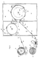
- FIG. 2 is a schematic drawing of an apparatus capable of performing a preferred method of the present invention, particularly illustrating material flow.
- FIG. 3 is an end elevational view of an apparatus capable of performing a preferred method of the present invention.
- FIG. 4 is an enlarged, partial sectional view taken along 4-4 of FIG. 3 particularly illustrating the direction of fluid flow through
fluid recirculation chamber 40 of the FIG. 3 apparatus. - FIG. 5 is an enlarged, pictorial partial sectional view taken from FIG. 2 illustrating a preferred nonwoven fibrous panel of the invention.
- FIG. 6 is an enlarged, partial sectional view of the heat drum of FIG. 2 illustrating
pin ring 90 secured around the circumference ofheat drum 14. - The first block in the flow diagram of FIG. 1 represents Needled Web Formation. A preferred nonwoven needled web of the invention is a blend of at least a first and second type of loose fiber interengaged and consolidated together to form a coherent nonwoven fabric, the second fiber type being a thermoplastic fiber. The interengaging and consolidating may be accomplished by an operation known in the art as needlepunching on a needle loom having needles that punch into and withdraw from the webbing at a desired number of strokes per minute; see Adams et al. (U.S. Patent No. 4,424,250) for a more detailed description of needlepunching. Several different thermoplastic fibers are available for use as the second thermoplastic type of fiber in the preferred nonwoven needled web; these include, but are not limited to, polyethylene, polypropylene, polyester, nylon, polyphenylene sulfide, polyether sulfone, polyether-ether ketone, vinyon, and bicomponent thermoplastic fibers. Nylon fibers, as defined by the U.S. Federal Trade Commission, are made from a manufactured substance which is any long chain synthetic polyamide having recurring amide groups (-NH-CO-) as an integral part of the polymer chain; and include those nylon fibers derived from the polyamide condensation product of hexamethylenediamine and adipic acid (i.e. Nylon 6,6), as well as those derived from the polycondensation of epsilon caprolactam (i.e. Nylon 6). The Phillips Petroleum Company manufactures and sells a suitable polyphenylene sulfide under the trademark "Ryton". Vinyon fibers have been defined as fibers made from a manufactured substance which is any long chain synthetic polymer composed of at least 85% by weight of vinyl chloride units. An example of a usable bicomponent thermoplastic fiber is one made of a polypropylene core and a polyethylene sheath. Chisso Corporation of Japan manufactures a suitable bicomponent polyolefin fiber sold as "Chisso ES" fiber.
- The first type of fiber in the preferred nonwoven needled web can be either (1) a non-thermoplastic fiber or (2) a thermoplastic fiber having a temperature melting point higher than that of the second thermoplastic type of fiber used in the needled web. Suitable non-thermoplastic fibers available for use as the first type of fiber include, but are not limited to, wool, cotton, acrylic, polybenzimidazole, aramid, rayon or other cellulosic material, carbon, glass, and novoloid fibers. Due to their very high temperature stability, for purposes of the present invention polybenzimidazoles have been characterized as non-thermoplastics. Polybenzimidazoles are a class of linear polymers whose repeat unit contains a benzimidazole moiety. PBI is the acronym commonly used for the poly-[2,2'-(m-phenylene)-5,5'-bibenzimidazole] (1) that is commercially available from Celanese Corp. (Charlotte, N.C.). Aramid fibers, as defined by the U.S. Federal Trade Commission, are made from a manufactured substance which is a long chain synthetic polyamide having at least 85% of its amide linkages (-NH-CO-) attached directly to two aromatic rings; and include those aramid fibers derived from poly(m-phenyleneisophthalamide) such as "Nomex" fibers (a registered trademark of E.I. du Pont de Nemours & Co.), as well as those derived from poly(p-phenyleneterephthalamide) such as "Kevlar" fibers (a registered trademark of E.I. du Pont de Nemours & Co.). Novoloid fibers have been defined as fibers made of a manufactured substance which contains at least 85% by weight of a cross-linked novolac. American Kynol, Inc., a division of the Japanese corporation Nippon Kynol, sells a suitable novoloid fiber under the registered trademark "Kynol".
- If the first type of fibers in the preferred nonwoven needled web are thermoplastic, the thermoplastic used must have a higher temperature melting point than the temperature melting point of the second thermoplastic type of fibers used in the web so that the second thermoplastic type can be melted without melting the first type. If the first type of fibers are thermoplastic, any of the thermoplastics described above as being available for the second type of fibers are also available for the first type of fibers as long as the consideration stated immediately above is met. If desired, the preferred nonwoven needled web may have components in addition to the above-described first and second type of fibers.
- A preferred nonwoven needled web which has only first and second type of fibers may have up to 20% of second thermoplastic type fibers and correspondingly up to 80% of first type fibers. By way of example, a nonwoven needled web could have 13%-15% polyethylene second type fibers and, correspondingly, 87%-85% polypropylene first type fibers. Other example combinations include: low melt polyester copolymer second type fibers with polyester first type fibers; polypropylene second type fibers with polyester first type fibers; polyethylene second type fibers with polyester first type fibers; and low melt polyester second type fibers with polypropylene first type fibers. First and second type fiber combinations are in no way limited to these examples.
- The second block in the flow diagram of FIG. 1 states "Needlepunching Web to Produce Textured Outer Surface". A process known as structured needlepunching (see
apparatus 46 illustrated schematically in FIG. 2) may be used to produce a "velour-like" textured outer surface of the preferred nonwoven needled web. Such needlepunching may involve the use of fork-end shaped needles or barbed needles (known as crown needles which derive their name from the unique spacing of the barbs). Theneedles 47 in FIG. 2, will strike into and through the preferred nonwoven needled web and into aweb supporting portion 48 in FIG. 2, to produce loops (if fork-end shaped needles are used) or raised, free ends (if crown needles are used) of the fibers in the web. Structured needlepunching will be described in more detail with FIG. 2. Velours are generally soft fabrics with a short thick pile having a velvetlike texture; they are often made of cotton, wool, a cotton warp in wool, silk, or mohair. - The third block in the diagram of FIG. 1 which says "Passing Fluid Through Needlepunched Web in Direction from Textured Outer Surface" will be discussed in conjunction with the descriptions of FIGS. 2-4. Suitable gases or liquids capable of being heated may be used as the fluid such as air or water. As suggested by the flow diagram, the heated web may then be, among other things, either (1) cooled and stored or cut into pieces/lengths, or (2) cut into pieces/lengths and thermally formed or molded by adding heat and pressure, into any three dimensional shape. If the lowest flow diagram block is performed, care must be taken not to soften, melt, and/or crush the loops, raised free ends, or the like, of fibers if it is desired that the product keep its velour-like textured outer surface.
- Nonwoven fibrous panels produced according to the method of the invention may be used for vehicle trunk or passenger compartment linings, seat backs, kick panels, seating, as well as pack- age/storage shelving, or for any use requiring a dimensionally stable fabric. Such nonwoven fibrous panels will have a minimum amount of fiber pullout wear.
- FIG. 2 illustrates roll 42 of a preferred nonwoven needled
web 52 being unwound indirection 44.Needled web 52 is passed throughneedlepunching apparatus 46 to produce a textured outer surface shown asloops 54. Both first and second type fibers of preferred nonwoven needledweb 52, as well as any other fiber components interengaged uniformly therein, will become loops, raised free ends, or the like, of texturedouter surface 54. The proportions of first and second type fibers in a preferred textured outer surface will be generally the same as their proportions in the needled web (the enlarged partial sectional of FIG. 5 illustrates theweb 52 and itsouter surface 54 in more detail).Needles 47 may be of various configurations to produce various velour-like outer surfaces--for simplicity onlyloops 54 are shown. Examples ofacceptable needlepunching apparatuses 47 are: fork-end shaped needle Structuring Machines NL 11/S and NL 11/SM supplied by Fehrer AG of Austria; and crown needle Di-Lour and NL 21 RV (Random Velour) looms manufactured by, respectively, Dilo, Inc. and Fehrer AG. Since it is likely that the speed at whichweb 52 is pulled throughneedlepunching apparatus 46 will be different than the speed ofweb 52 during the remaining illustrated process, there is shown a break point ofweb 52. This break indicates the point at which the web with its textured outer surface could be rolled for storage so that it can later be introduced into the remaining illustrated process at any convenient time. - Guide rollers 50a-f are used to guide the needled
web 52 with texturedouter surface 54 through the apparatus of FIG. 2 in the direction shown at 56, 58, 68.Web 52 entersfluid recirculation chamber 40, defined byheat chamber housing 12, through opening 41 where it is guided ontoheat drum 14 by guide roller 50c.Heat drum 14 hasapertures 16 located throughout as better seen in FIG. 1, and rotates indirection 58 aroundshaft 18. Texturedouter surface 54 rides overheat drum 14 facing outwardly so that it will not be crushed or have its velour-like texture and appearance destroyed. Fan means 28 shown in dashed lines representing a squirrel cage type fan behindheat drum 14, can be positioned as illustrated. Fan means 29 (described in more detail with FIG. 4) will pull the fluid used to melt the second thermoplastic type fibers, throughweb 52 andapertures 16 into drum chamber 60. By pulling such fluid (heated to a temperature that will melt at least a portion of the second thermoplastic type fibers to produce weld joints, not shown, thereof) in a direction fromrecirculation chamber 40 into drum chamber 60, liquefied second thermoplastic type fibers will be pulled away from the texturedouter surface 54. Upon rehardening of the small liquefied thermoplastic clumps created, the textured outer surface should remain generally velour-like in texture and appearance. In operation, fan means 29 will effectively create a pressure gradient acrossweb 52 resulting in the movement of the fluid found inrecirculation chamber 40 in a direction from therecirculation chamber 40 into drum chamber 60. Please see FIG. 4 to better understand the fluid circulation throughchambers 40 and 60. - Preferably, a needled
web 52 of only first and second type fibers is made of up to 20% second thermoplastic type fibers interengaged and consolidated together, as mentioned above. Thus, after at least a portion of second thermoplastic type fibers are heated to their melt temperature, a preferable nonwoven panel produced that has at least a majority, if not all, of its first type fibers left in tact will remain mostly fibrous. Furthermore, since approximately the same proportion (i.e. up to 20%) of second thermoplastic type fibers will be found in a preferred textured outer surface, as mentioned above, a preferable nonwoven panel produced according to the method described in the above paragraph, will have, after processing, a textured outer surface substantially free of second thermoplastic type fibers. It can be appreciated that weld joints (not shown) produced of second thermoplastic type fibers according to the method described in the above paragraph, will generally be concentrated away from the textured outer surface in a preferred nonwoven panel, leaving the textured outer surface velour-like in texture and appearance. Once the second thermoplastic type fibers have been melted, it is believed gravity may play some role in the final location of weld joints at very low fluid flow rates throughweb 52. -
Guide roller 50d preferably has a tension sufficient to pullweb 52 fromheat drum 14, yet not crush texturedouter surface 54. Guide roller 50e guidesweb 52 ontocool drum 64 which rotates aroundshaft 66 indirection 68 within coolingchamber 70, defined byhousing 62.Guide roller 50f guides web off coolingdrum 64.Surface winding rollers 74, driven in the direction indicated,wind web 52 aroundspool 73 or other suitable device intoroll 72 for storage. Although not shown, the nonwoven panel(s) may be cut and thermally formed prior to preparing the product for storage. Note thatheat chamber housing 12, coolingchamber housing 62,heat drum 14, and coolingdrum 64 can be made of a metal, metal alloy, or other suitable material having sufficient strength and heat resistance. -
Apparatus 10 of FIG. 3 includes aheat drum 14 withapertures 16 and enclosed atend 17 by a circular plate (shown at 15 in FIG. 4), capable of being rotated byshaft 18.Heat drum 14 may be driven in a conventional manner by means of' anelectric motor 20 connected by suitable drive belting 22 to a drivepulley 24. To simplify the diagram, needledweb 52 and its texturedouter surface 54 have been left out of FIG. 3.Fluid recirculation chamber 40, defined byheat chamber housing 12, is shown to contain the following:heat drum 14;burner housing 26 suitably mounted onbase 27; fan means 28; as well as flaredconduit 30.Shaft 32 for fan means 28 is driven independently fromheat drum shaft 18 and may be driven in a conventional manner byelectric motor 34 connected by suitable drive belting 36 to a drivepulley 38. Although fan means 28 is illustrated as a squirrel cage fan, any suitable fan configuration may be used to recirculate fluid throughrecirculation chamber 40 at a prescribed flow rate. A suitable burner (not shown) for heating a suitable recirculating fluid such as air, is a liquid propane Eclipse burner having a rating of 2 million BTUs. To operate properly, liquid propane burners such as the Eclipse burner generally need an intake of fresh air from outside therecirculation chamber 40. A burner fresh air intake is not illustrated in FIG. 3. - The partial sectional in FIG. 4 illustrates the
direction 80 of fluid flow through fluid recirculation chamber 40: in operation, fan means 28 draws the fluid such as air throughapertures 16 into drum chamber 60 then through burner housing chamber 82 (burner not shown) to be heated and, finally, through flared conduit chamber 84. If fan means 28 takes some other configuration than that shown, such as a blade fan housed by suitable housing, the fan would exhaust the fluid out of its housing into therecirculation chamber 40 to be reused.Web 52, absent in FIG. 4, will be guided ontoheat drum 14 with its texturedouter surface 54 facing outwardly so that the heated fluid passes through the web in a direction from the textured outer surface toward theheat drum 14.Shaft 18 extends the length ofheat drum 14 and is supported at each end by suitable means. Also shown in FIG. 4 is afume exhaust pipe 86 through which, by suitable exhaust fan (not shown), any fumes given off by the melting of second thermoplastic type fibers will be discharged along direction 88. - FIG. 6 illustrates
pin ring 90 made up ofmetal sections 91 having pins 92 therethrough, fastened by suitable means 94 to metal belting 96. A minimum of two pin rings 90 strapped aroundheat drum 14 at a width slightly less than the width of a preferred needled web 52 (yet unheated), may serve as a means of minimizing shrinkage ofweb 52 during heating by the recirculating fluid by spearing and holding the edges ofweb 52 to the heat drum. - By way of example, a nonwoven needled web was prepared of 13% 6 denier undyed natural polyethylene fiber and 87% 18 denier solution dyed polypropylene fiber was blended by interengaging and consolidating with a needlepunching machine, the loose fibers of approximately 6.35 cm to 8.89 cm (2.5"-3.5") in length to form a generally uniform needled web. The polyethylene has a temperature melting point of 230-250 ° F and the polypropylene has a temperature melting point of 160°C to 176.7°C (320-350 °F). The needled web was then needlepunched with fork-end shaped needles to produce an outer surface of loops of both polyethylene and polypropylene fibers. The web with its looped outer surface was then guided onto a heat drum of approximately 177.8 cm (70") in diameter at a rate of approximately 0,1016-0,1524 metres per second (20-30 feet per minute). The heat drum was driven by an electric motor. An Eclipse burner heated air to a temperature of approximately 129.4°C (265 °F) to melt at least a portion of the polyethylene fibers in the web. A fan having a diameter of approximately 1.219 metres (4 feet) capable of providing a flow rate of .914 to 9.14 litres per minute/cm2 (30-300 cfm/ft2) (cubic feet per minute per square foot of web) was used to draw heated air through the fluid recirculation chamber at a flow rate of approximately (2.742 litres per min/cm2) 90 cfm/ft2 (cubic feet per minute per square foot of web). Cooling
chamber 70 was held at approximately room temperature 21.1 0 C (70 ° F). - While certain representative embodiments and details have been shown for the purpose of illustrating the invention, it will be apparent to those skilled in the art that various modifications may be made to the invention without departing from the spirit or scope of the invention.
Claims (19)
Applications Claiming Priority (3)
| Application Number | Priority Date | Filing Date | Title |
|---|---|---|---|
| US07/457,998 US5077874A (en) | 1990-01-10 | 1990-01-10 | Method of producing a nonwoven dibrous textured panel and panel produced thereby |
| US457998 | 1990-01-10 | ||
| PCT/US1991/000154 WO1991010768A1 (en) | 1990-01-10 | 1991-01-08 | Method of producing a nonwoven fibrous textured panel and panel produced thereby |
Publications (3)
| Publication Number | Publication Date |
|---|---|
| EP0462272A1 EP0462272A1 (en) | 1991-12-27 |
| EP0462272B1 true EP0462272B1 (en) | 1995-04-19 |
| EP0462272B2 EP0462272B2 (en) | 2003-05-07 |
Family
ID=23818940
Family Applications (1)
| Application Number | Title | Priority Date | Filing Date |
|---|---|---|---|
| EP91904310A Expired - Lifetime EP0462272B2 (en) | 1990-01-10 | 1991-01-08 | Method of producing a nonwoven fibrous textured panel and panel produced thereby |
Country Status (13)
| Country | Link |
|---|---|
| US (1) | US5077874A (en) |
| EP (1) | EP0462272B2 (en) |
| JP (1) | JP2647742B2 (en) |
| KR (1) | KR950009489B1 (en) |
| AT (1) | ATE121468T1 (en) |
| AU (1) | AU634132B2 (en) |
| BR (1) | BR9104048A (en) |
| DE (1) | DE69108987T3 (en) |
| ES (1) | ES2071301T5 (en) |
| MX (1) | MX173580B (en) |
| RU (1) | RU2081221C1 (en) |
| WO (1) | WO1991010768A1 (en) |
| YU (1) | YU48233B (en) |
Families Citing this family (23)
| Publication number | Priority date | Publication date | Assignee | Title |
|---|---|---|---|---|
| US5269994A (en) * | 1992-04-10 | 1993-12-14 | Basf Corporation | Nonwoven bonding technique |
| EP0593716B1 (en) * | 1992-05-08 | 1998-10-14 | Gates Formed-Fibre Products Inc. | Nonwoven moldable composite and method of manufacture |
| JP3527507B2 (en) * | 1992-08-04 | 2004-05-17 | 帝人ファイバー株式会社 | Heat-resistant flame-retardant cushion material and vehicle seat |
| FR2700782B1 (en) * | 1993-01-26 | 1995-04-14 | Libeltex Nv Sa | Method of manufacturing a nonwoven and nonwoven obtained by this process. |
| US5902663A (en) * | 1993-09-01 | 1999-05-11 | Fibertex A/S | Low-stretch and dimension stable floor covering |
| US5545276A (en) * | 1994-03-03 | 1996-08-13 | Milliken Research Corporation | Process for forming cushion backed carpet |
| US5698480A (en) * | 1994-08-09 | 1997-12-16 | Hercules Incorporated | Textile structures containing linear low density polyethylene binder fibers |
| US6117546A (en) * | 1996-03-03 | 2000-09-12 | Hercules Incorporated | Yarns containing linear low density polyethylene fibers |
| US7338698B1 (en) | 1997-02-28 | 2008-03-04 | Columbia Insurance Company | Homogeneously branched ethylene polymer carpet, carpet backing and method for making same |
| US6008149A (en) * | 1997-04-23 | 1999-12-28 | Knowlton Nonwovens, Inc. | Moldable composite article and method of manufacture |
| US6086984A (en) * | 1998-05-22 | 2000-07-11 | Delaware Valley Corporation | Elastic nonwoven fabric |
| GB2342362B (en) * | 1998-10-02 | 2002-12-24 | Rawson Carpets Ltd | Floor covering |
| US20050269850A1 (en) * | 1999-11-24 | 2005-12-08 | Total Innovative Manufacturing, Llc | Removable seat cushion |
| US20020034606A1 (en) * | 2000-06-05 | 2002-03-21 | Miller Scott C. | Low weight cushioned carpet, carpet tile and method |
| US20020142126A1 (en) * | 2000-11-24 | 2002-10-03 | Higgins Kenneth B. | Textile product and method |
| US7182989B2 (en) | 2002-07-31 | 2007-02-27 | Milliken & Company | Flooring system and method |
| US20030161990A1 (en) * | 2001-07-20 | 2003-08-28 | Higgins Kenneth B. | Residential carpet product and method |
| US20030170420A1 (en) * | 2001-07-20 | 2003-09-11 | Higgins Kenneth B. | Residential carpet product and method |
| US20050091936A1 (en) * | 2003-11-05 | 2005-05-05 | Galloway Kerry T. | Carpeting systems, methods and products |
| US20050287334A1 (en) * | 2004-06-29 | 2005-12-29 | Wright Jeffery J | Cushioned flooring products |
| US20090220729A1 (en) * | 2006-03-24 | 2009-09-03 | Francois Roederer | Needle-Punched Glass Mat |
| RU2317198C1 (en) * | 2006-06-23 | 2008-02-20 | Общество с ограниченной ответственностью Управляющая компания "Профит Центр Плюс" | Method of manufacture of the glass-fiber housing used, for example, for the locomotive gear box and the housing manufactured by this method |
| RU2690573C1 (en) * | 2018-10-02 | 2019-06-04 | Общество с ограниченной ответственностью "ТЕРМОПОЛ" | Nonwoven heat-insulating material with thermal generation effect |
Family Cites Families (34)
| Publication number | Priority date | Publication date | Assignee | Title |
|---|---|---|---|---|
| DE1660791A1 (en) * | 1966-05-31 | 1972-02-17 | Vepa Ag | Method and device for consolidating needle felt, felt and similar products |
| US3774273A (en) * | 1970-02-20 | 1973-11-27 | Toray Industries | Needle felting apparatus |
| US3950587A (en) * | 1971-01-12 | 1976-04-13 | Breveteam, S.A. | Non-woven textile fiber products having a relief-like structure |
| GB1427711A (en) * | 1972-05-05 | 1976-03-10 | Ici Ltd | Non-woven structures |
| US3889028A (en) † | 1972-07-18 | 1975-06-10 | Ici Ltd | Non-woven materials |
| JPS50132725A (en) * | 1974-04-08 | 1975-10-21 | ||
| US3953632A (en) * | 1974-04-29 | 1976-04-27 | Woodall Industries Inc. | Resin impregnated mats and method of making the same |
| US4016318A (en) * | 1976-07-16 | 1977-04-05 | General Latex And Chemical Corporation | Automotive carpet mat and method of preparing same |
| JPS5346382U (en) * | 1976-09-27 | 1978-04-20 | ||
| US4230755A (en) * | 1976-11-23 | 1980-10-28 | C. H. Masland & Sons | Moldable unitary composite carpet structure |
| GB1596025A (en) * | 1977-03-03 | 1981-08-19 | Ici Ltd | Shaped nonwoven fabrics |
| US4199634A (en) * | 1977-03-04 | 1980-04-22 | Polysar Limited | Methods of making sound insulation moldable carpets |
| SE428381B (en) * | 1977-04-07 | 1983-06-27 | Nordifa Industritextilier | FORMAT TEXTILE PANEL AND PROCEDURE FOR ITS MANUFACTURING |
| US4324752A (en) * | 1977-05-16 | 1982-04-13 | Phillips Petroleum Company | Process for producing a fused fabric |
| US4342813A (en) * | 1978-03-14 | 1982-08-03 | Phillips Petroleum Company | Method for the production of a fused nonwoven fabric |
| US4298643A (en) * | 1978-04-14 | 1981-11-03 | Toyo Boseki Kabushiki Kaisha | Fiber sheet for forming |
| DE2834473C2 (en) * | 1978-08-05 | 1982-11-18 | Fa. Carl Freudenberg, 6940 Weinheim | Process for the production of a car carpet which is deformable when heated |
| US4186230A (en) * | 1978-10-02 | 1980-01-29 | The Goodyear Tire & Rubber Company | Thermoplastic moldable latex foam mat |
| US4242395A (en) * | 1978-12-18 | 1980-12-30 | J. P. Stevens & Co., Inc. | Thermoplastic compositions and automotive carpeting backed therewith |
| US4258094A (en) * | 1979-04-26 | 1981-03-24 | Brunswick Corporation | Melt bonded fabrics and a method for their production |
| US4320167A (en) * | 1979-11-19 | 1982-03-16 | Phillips Petroleum Company | Nonwoven fabric and method of production thereof |
| US4390582A (en) * | 1980-06-16 | 1983-06-28 | Ozite Corporation | Cut pile fabric with carrier and texturized loops |
| US4315965A (en) * | 1980-06-20 | 1982-02-16 | Scott Paper Company | Method of making nonwoven fabric and product made thereby having both stick bonds and molten bonds |
| US4474846A (en) * | 1981-04-06 | 1984-10-02 | Van Dresser Corporation | Moldable fibrous mat and product molded therefrom |
| IT1138319B (en) * | 1981-05-07 | 1986-09-17 | Honeywell Inf Systems | CONTINUOUS PRINTING FORM FOR OFFICE AUTOMATION |
| US4359132A (en) * | 1981-05-14 | 1982-11-16 | Albany International Corp. | High performance speaker diaphragm |
| US4424250A (en) * | 1982-04-21 | 1984-01-03 | Albany International Corp. | Carpet faced textile panel |
| JPS6019509A (en) * | 1983-07-13 | 1985-01-31 | 株式会社栗本鉄工所 | Production unit for reinforcing fiber premixed mortar |
| US4568581A (en) * | 1984-09-12 | 1986-02-04 | Collins & Aikman Corporation | Molded three dimensional fibrous surfaced article and method of producing same |
| US4581272A (en) * | 1985-01-11 | 1986-04-08 | Gates Formed-Fibre Products, Inc. | Automotive vehicle door kick panel and method of manufacture |
| US4668562A (en) * | 1986-04-16 | 1987-05-26 | Cumulus Fibres, Inc. | Vacuum bonded non-woven batt |
| US4765671A (en) † | 1986-10-14 | 1988-08-23 | Gates Formed-Fibre Products, Inc. | Low modulus cargo bed liner |
| US4780359A (en) * | 1987-04-03 | 1988-10-25 | Gates Formed-Fibre Products, Inc. | Fire retardent structural textile panel |
| JPH01174658A (en) * | 1987-12-29 | 1989-07-11 | Kanai Hiroyuki | Production of interior substrate for automobile |
-
1990
- 1990-01-10 US US07/457,998 patent/US5077874A/en not_active Expired - Lifetime
-
1991
- 1991-01-08 BR BR919104048A patent/BR9104048A/en not_active IP Right Cessation
- 1991-01-08 JP JP3504364A patent/JP2647742B2/en not_active Expired - Fee Related
- 1991-01-08 KR KR1019910701100A patent/KR950009489B1/en not_active Expired - Fee Related
- 1991-01-08 WO PCT/US1991/000154 patent/WO1991010768A1/en not_active Ceased
- 1991-01-08 EP EP91904310A patent/EP0462272B2/en not_active Expired - Lifetime
- 1991-01-08 AT AT91904310T patent/ATE121468T1/en not_active IP Right Cessation
- 1991-01-08 AU AU72500/91A patent/AU634132B2/en not_active Expired
- 1991-01-08 DE DE69108987T patent/DE69108987T3/en not_active Expired - Fee Related
- 1991-01-08 ES ES91904310T patent/ES2071301T5/en not_active Expired - Lifetime
- 1991-01-08 RU SU915001907A patent/RU2081221C1/en not_active IP Right Cessation
- 1991-01-09 MX MX024105A patent/MX173580B/en unknown
- 1991-01-10 YU YU3391A patent/YU48233B/en unknown
Also Published As
| Publication number | Publication date |
|---|---|
| BR9104048A (en) | 1991-12-10 |
| KR950009489B1 (en) | 1995-08-23 |
| ES2071301T5 (en) | 2003-12-16 |
| WO1991010768A1 (en) | 1991-07-25 |
| EP0462272B2 (en) | 2003-05-07 |
| ATE121468T1 (en) | 1995-05-15 |
| ES2071301T3 (en) | 1995-06-16 |
| AU634132B2 (en) | 1993-02-11 |
| YU48233B (en) | 1997-08-22 |
| AU7250091A (en) | 1991-08-05 |
| EP0462272A1 (en) | 1991-12-27 |
| JPH04506551A (en) | 1992-11-12 |
| JP2647742B2 (en) | 1997-08-27 |
| RU2081221C1 (en) | 1997-06-10 |
| KR920701554A (en) | 1992-08-12 |
| DE69108987T3 (en) | 2004-01-08 |
| DE69108987D1 (en) | 1995-05-24 |
| US5077874A (en) | 1992-01-07 |
| DE69108987T2 (en) | 1995-08-31 |
| MX173580B (en) | 1994-03-16 |
| YU3391A (en) | 1994-06-24 |
Similar Documents
| Publication | Publication Date | Title |
|---|---|---|
| EP0462272B2 (en) | Method of producing a nonwoven fibrous textured panel and panel produced thereby | |
| US5199141A (en) | Method of producing a nonwoven fibrous textured panel and panel produced thereby | |
| US3819465A (en) | Non-woven textile products | |
| US4379189A (en) | Nonwoven textile fabric with fused face and raised loop pile | |
| US7005395B2 (en) | Stretchable composite sheets and processes for making | |
| US6053719A (en) | Apparatus for the manufacture of a spun nonwoven fabric | |
| JPS6051586B2 (en) | Nonwoven fabric manufacturing method and device | |
| US3348993A (en) | Fabrics | |
| US5481786A (en) | Method of manufacturing a recyclable carpet | |
| CN112659687A (en) | Tufted chemical fiber carpet capable of being completely recycled and preparation method thereof | |
| US7174612B2 (en) | Nonwoven fabrics containing yarns with varying filament characteristics | |
| EP1456017B1 (en) | Stretchable composite sheets and processes for making | |
| EP0503048A1 (en) | Rigid fiber composite | |
| JPH0564856A (en) | Combined lining cloth and its preparation | |
| JPH04257358A (en) | Needle nonwoven fabric | |
| CA2007488C (en) | Method of producing a nonwoven fibrous textured panel and panel produced thereby | |
| EP1360357B1 (en) | Hydroentanglement of continuous polymer filaments | |
| MXPA05004293A (en) | Nonwoven secondary carpet backing. | |
| JPH0796747B2 (en) | Method for manufacturing needle spunbond fabric | |
| JP2997404B2 (en) | Reinforced spunbond nonwoven | |
| GB1590102A (en) | Stabilised fabrics | |
| CN214449173U (en) | A fully recyclable tufted chemical fiber carpet | |
| JP2019500990A (en) | An event or exhibition carpet using solid multileaf fibers | |
| JPH0386536A (en) | Laminated unwoven fabric sheet | |
| JPH08224158A (en) | Pile-like rug and method of manufacturing the same |
Legal Events
| Date | Code | Title | Description |
|---|---|---|---|
| PUAI | Public reference made under article 153(3) epc to a published international application that has entered the european phase |
Free format text: ORIGINAL CODE: 0009012 |
|
| 17P | Request for examination filed |
Effective date: 19910913 |
|
| AK | Designated contracting states |
Kind code of ref document: A1 Designated state(s): AT BE DE ES FR GB IT SE |
|
| 17Q | First examination report despatched |
Effective date: 19931007 |
|
| GRAA | (expected) grant |
Free format text: ORIGINAL CODE: 0009210 |
|
| AK | Designated contracting states |
Kind code of ref document: B1 Designated state(s): AT BE DE ES FR GB IT SE |
|
| REF | Corresponds to: |
Ref document number: 121468 Country of ref document: AT Date of ref document: 19950515 Kind code of ref document: T |
|
| REF | Corresponds to: |
Ref document number: 69108987 Country of ref document: DE Date of ref document: 19950524 |
|
| REG | Reference to a national code |
Ref country code: ES Ref legal event code: FG2A Ref document number: 2071301 Country of ref document: ES Kind code of ref document: T3 |
|
| ITF | It: translation for a ep patent filed | ||
| ET | Fr: translation filed | ||
| PLBQ | Unpublished change to opponent data |
Free format text: ORIGINAL CODE: EPIDOS OPPO |
|
| PLAV | Examination of admissibility of opposition |
Free format text: ORIGINAL CODE: EPIDOS OPEX |
|
| PLBI | Opposition filed |
Free format text: ORIGINAL CODE: 0009260 |
|
| PLBQ | Unpublished change to opponent data |
Free format text: ORIGINAL CODE: EPIDOS OPPO |
|
| PLBQ | Unpublished change to opponent data |
Free format text: ORIGINAL CODE: EPIDOS OPPO |
|
| PLBI | Opposition filed |
Free format text: ORIGINAL CODE: 0009260 |
|
| PLBQ | Unpublished change to opponent data |
Free format text: ORIGINAL CODE: EPIDOS OPPO |
|
| PLAB | Opposition data, opponent's data or that of the opponent's representative modified |
Free format text: ORIGINAL CODE: 0009299OPPO |
|
| PLAV | Examination of admissibility of opposition |
Free format text: ORIGINAL CODE: EPIDOS OPEX |
|
| PLBF | Reply of patent proprietor to notice(s) of opposition |
Free format text: ORIGINAL CODE: EPIDOS OBSO |
|
| 26 | Opposition filed |
Opponent name: FLEISSNER GMBH & CO. MASCHINENFABRIK Effective date: 19960111 |
|
| 26 | Opposition filed |
Opponent name: ASOTA GESELLSCHAFT M.B.H. Effective date: 19960118 Opponent name: FLEISSNER GMBH & CO. MASCHINENFABRIK Effective date: 19960111 Opponent name: MILLIKEN RESEARCH CORPORATION Effective date: 19960119 |
|
| R26 | Opposition filed (corrected) |
Opponent name: FLEISSNER GMBH & CO. MASCHINENFABRIK * 960118 ASOT Effective date: 19960111 |
|
| PLBF | Reply of patent proprietor to notice(s) of opposition |
Free format text: ORIGINAL CODE: EPIDOS OBSO |
|
| PLBF | Reply of patent proprietor to notice(s) of opposition |
Free format text: ORIGINAL CODE: EPIDOS OBSO |
|
| PLBF | Reply of patent proprietor to notice(s) of opposition |
Free format text: ORIGINAL CODE: EPIDOS OBSO |
|
| PLBQ | Unpublished change to opponent data |
Free format text: ORIGINAL CODE: EPIDOS OPPO |
|
| PLAB | Opposition data, opponent's data or that of the opponent's representative modified |
Free format text: ORIGINAL CODE: 0009299OPPO |
|
| R26 | Opposition filed (corrected) |
Opponent name: FLEISSNER GMBH & CO. MASCHINENFABRIK * 19960118 AS Effective date: 19960111 |
|
| PLAW | Interlocutory decision in opposition |
Free format text: ORIGINAL CODE: EPIDOS IDOP |
|
| APAC | Appeal dossier modified |
Free format text: ORIGINAL CODE: EPIDOS NOAPO |
|
| APAE | Appeal reference modified |
Free format text: ORIGINAL CODE: EPIDOS REFNO |
|
| APAC | Appeal dossier modified |
Free format text: ORIGINAL CODE: EPIDOS NOAPO |
|
| PLBQ | Unpublished change to opponent data |
Free format text: ORIGINAL CODE: EPIDOS OPPO |
|
| PLAB | Opposition data, opponent's data or that of the opponent's representative modified |
Free format text: ORIGINAL CODE: 0009299OPPO |
|
| REG | Reference to a national code |
Ref country code: GB Ref legal event code: IF02 |
|
| R26 | Opposition filed (corrected) |
Opponent name: FLEISSNER GMBH & CO. MASCHINENFABRIK * 19960118 AS Effective date: 19960111 |
|
| APAC | Appeal dossier modified |
Free format text: ORIGINAL CODE: EPIDOS NOAPO |
|
| PLAW | Interlocutory decision in opposition |
Free format text: ORIGINAL CODE: EPIDOS IDOP |
|
| PUAH | Patent maintained in amended form |
Free format text: ORIGINAL CODE: 0009272 |
|
| STAA | Information on the status of an ep patent application or granted ep patent |
Free format text: STATUS: PATENT MAINTAINED AS AMENDED |
|
| 27A | Patent maintained in amended form |
Effective date: 20030507 |
|
| AK | Designated contracting states |
Designated state(s): AT BE DE ES FR GB IT SE |
|
| REG | Reference to a national code |
Ref country code: SE Ref legal event code: RPEO |
|
| REG | Reference to a national code |
Ref country code: ES Ref legal event code: DC2A Date of ref document: 20030703 Kind code of ref document: T5 |
|
| ET3 | Fr: translation filed ** decision concerning opposition | ||
| PGFP | Annual fee paid to national office [announced via postgrant information from national office to epo] |
Ref country code: AT Payment date: 20031219 Year of fee payment: 14 |
|
| PGFP | Annual fee paid to national office [announced via postgrant information from national office to epo] |
Ref country code: GB Payment date: 20031230 Year of fee payment: 14 |
|
| PGFP | Annual fee paid to national office [announced via postgrant information from national office to epo] |
Ref country code: FR Payment date: 20040122 Year of fee payment: 14 Ref country code: SE Payment date: 20040122 Year of fee payment: 14 |
|
| PGFP | Annual fee paid to national office [announced via postgrant information from national office to epo] |
Ref country code: ES Payment date: 20040212 Year of fee payment: 14 |
|
| PGFP | Annual fee paid to national office [announced via postgrant information from national office to epo] |
Ref country code: BE Payment date: 20040216 Year of fee payment: 14 |
|
| PGFP | Annual fee paid to national office [announced via postgrant information from national office to epo] |
Ref country code: DE Payment date: 20040301 Year of fee payment: 14 |
|
| PG25 | Lapsed in a contracting state [announced via postgrant information from national office to epo] |
Ref country code: AT Free format text: LAPSE BECAUSE OF NON-PAYMENT OF DUE FEES Effective date: 20050108 Ref country code: GB Free format text: LAPSE BECAUSE OF NON-PAYMENT OF DUE FEES Effective date: 20050108 |
|
| PG25 | Lapsed in a contracting state [announced via postgrant information from national office to epo] |
Ref country code: SE Free format text: LAPSE BECAUSE OF NON-PAYMENT OF DUE FEES Effective date: 20050109 |
|
| PG25 | Lapsed in a contracting state [announced via postgrant information from national office to epo] |
Ref country code: ES Free format text: LAPSE BECAUSE OF NON-PAYMENT OF DUE FEES Effective date: 20050110 |
|
| PG25 | Lapsed in a contracting state [announced via postgrant information from national office to epo] |
Ref country code: BE Free format text: LAPSE BECAUSE OF NON-PAYMENT OF DUE FEES Effective date: 20050131 |
|
| BERE | Be: lapsed |
Owner name: *GATES FORMED-FIBRE PRODUCTS INC. Effective date: 20050131 |
|
| PG25 | Lapsed in a contracting state [announced via postgrant information from national office to epo] |
Ref country code: DE Free format text: LAPSE BECAUSE OF NON-PAYMENT OF DUE FEES Effective date: 20050802 |
|
| EUG | Se: european patent has lapsed | ||
| GBPC | Gb: european patent ceased through non-payment of renewal fee |
Effective date: 20050108 |
|
| PG25 | Lapsed in a contracting state [announced via postgrant information from national office to epo] |
Ref country code: FR Free format text: LAPSE BECAUSE OF NON-PAYMENT OF DUE FEES Effective date: 20050930 |
|
| APAH | Appeal reference modified |
Free format text: ORIGINAL CODE: EPIDOSCREFNO |
|
| REG | Reference to a national code |
Ref country code: FR Ref legal event code: ST |
|
| REG | Reference to a national code |
Ref country code: ES Ref legal event code: FD2A Effective date: 20050110 |
|
| BERE | Be: lapsed |
Owner name: *GATES FORMED-FIBRE PRODUCTS INC. Effective date: 20050131 |
|
| PGFP | Annual fee paid to national office [announced via postgrant information from national office to epo] |
Ref country code: IT Payment date: 20090331 Year of fee payment: 18 |
|
| PGRI | Patent reinstated in contracting state [announced from national office to epo] |
Ref country code: IT Effective date: 20090601 |
|
| PGRI | Patent reinstated in contracting state [announced from national office to epo] |
Ref country code: IT Effective date: 20090601 |