EP0462099B1 - Crank drive - Google Patents
Crank drive Download PDFInfo
- Publication number
- EP0462099B1 EP0462099B1 EP19910890105 EP91890105A EP0462099B1 EP 0462099 B1 EP0462099 B1 EP 0462099B1 EP 19910890105 EP19910890105 EP 19910890105 EP 91890105 A EP91890105 A EP 91890105A EP 0462099 B1 EP0462099 B1 EP 0462099B1
- Authority
- EP
- European Patent Office
- Prior art keywords
- crank
- crank arm
- toothed
- toothed segments
- crankshaft
- Prior art date
- Legal status (The legal status is an assumption and is not a legal conclusion. Google has not performed a legal analysis and makes no representation as to the accuracy of the status listed.)
- Expired - Lifetime
Links
Images

Classifications
-
- F—MECHANICAL ENGINEERING; LIGHTING; HEATING; WEAPONS; BLASTING
- F16—ENGINEERING ELEMENTS AND UNITS; GENERAL MEASURES FOR PRODUCING AND MAINTAINING EFFECTIVE FUNCTIONING OF MACHINES OR INSTALLATIONS; THERMAL INSULATION IN GENERAL
- F16H—GEARING
- F16H21/00—Gearings comprising primarily only links or levers, with or without slides
- F16H21/10—Gearings comprising primarily only links or levers, with or without slides all movement being in, or parallel to, a single plane
- F16H21/16—Gearings comprising primarily only links or levers, with or without slides all movement being in, or parallel to, a single plane for interconverting rotary motion and reciprocating motion
- F16H21/18—Crank gearings; Eccentric gearings
- F16H21/22—Crank gearings; Eccentric gearings with one connecting-rod and one guided slide to each crank or eccentric
- F16H21/30—Crank gearings; Eccentric gearings with one connecting-rod and one guided slide to each crank or eccentric with members having rolling contact
-
- B—PERFORMING OPERATIONS; TRANSPORTING
- B62—LAND VEHICLES FOR TRAVELLING OTHERWISE THAN ON RAILS
- B62M—RIDER PROPULSION OF WHEELED VEHICLES OR SLEDGES; POWERED PROPULSION OF SLEDGES OR SINGLE-TRACK CYCLES; TRANSMISSIONS SPECIALLY ADAPTED FOR SUCH VEHICLES
- B62M3/00—Construction of cranks operated by hand or foot
- B62M3/02—Construction of cranks operated by hand or foot of adjustable length
- B62M3/04—Construction of cranks operated by hand or foot of adjustable length automatically adjusting
-
- F—MECHANICAL ENGINEERING; LIGHTING; HEATING; WEAPONS; BLASTING
- F16—ENGINEERING ELEMENTS AND UNITS; GENERAL MEASURES FOR PRODUCING AND MAINTAINING EFFECTIVE FUNCTIONING OF MACHINES OR INSTALLATIONS; THERMAL INSULATION IN GENERAL
- F16H—GEARING
- F16H37/00—Combinations of mechanical gearings, not provided for in groups F16H1/00 - F16H35/00
- F16H37/12—Gearings comprising primarily toothed or friction gearing, links or levers, and cams, or members of at least two of these types
Definitions
- the invention relates to a crank mechanism with a crankshaft rotatably mounted in a housing or the like and a crank consisting of a crank arm attached to the crankshaft in a rotationally fixed manner and a crank arm which is guided in a radially displaceable manner in the crank arm, whereby the crank arm stroke movement is converted into a crankshaft rotary movement an intermediate gear is provided with a toothed rack arranged on the crank arm in the stroke direction and correspondingly toothed transmission and support wheels each assigned to either the crank arm or the housing and the stroke movements according to alternately effective toothed segments.
- crank drives are used to convert a lifting movement into a rotary movement, the crank drives mostly working with crank arms of constant length, i.e. with a constant crank radius, and converting the lifting force acting on the crank pin into a useful torque that can be derived from the crankshaft.
- the lifting force can be broken down into a radial and a tangential component, of which so far the respective tangential component together with the crank radius determines the usable torque and the radial component is lost for the useful torque.
- crank angle 0 ° For each crank rotation there is a torque distribution dependent on the angular position of the crank arm, since the tangential component increases from top dead center (crank angle 0 °) to a quarter turn (crank angle 90 °) from 0 to a maximum and then to bottom dead center (crank angle 180 °) drops back to 0, etc.
- the useless radial component thus leads to a considerable loss of power and only about 63% of the force acting on the crank pin can be derived as torque from the crankshaft.
- crank drives with a crank arm that can be radially displaced in a crank cheek and an intermediate gear for converting the crank arm stroke movement into a crankshaft rotary movement.
- the intermediate gear consists of a crank arm-fixed toothed rack, transmission wheels rotatably mounted in the crank arm and housing-fixed, complementary semi-circular toothed segments, of which transmission wheels one serves as a pinion meshing with the toothed rack and two intermediate wheels are provided which are coaxial with and interlocking with the firmly supported toothed segments , so that a lifting movement of the rack causes a rotary movement of the transmission wheels, which thereby run on the toothed segments and bring about a constant rotational movement of the crank arm with the change of engagement between the two toothed segments.
- crank arm assumes its outermost radial position at a 90 ° crank angle and its innermost radial position at a crank angle of 270 ° and only reaches these extreme positions once per revolution.
- the crank arm should be extended in the area of the largest values of the tangential component and the effective torque increased, but additional use of the radial component for the force-torque conversion is only possible to a limited extent.
- the radial component even leads to a counter torque through the intermediate gear in the crank angle range from 0 ° to 180 °, which rather worsens the efficiency, since the advantages of the increased torque due to the extended crank arm on the one hand due to the reduced torque due to the shortened crank arm on the other side.
- the invention is therefore based on the object to remedy these shortcomings and to create a crank mechanism of the type described, which by additional use of the Radial component allows a significant increase in efficiency when converting a stroke movement into a rotary movement.
- the invention solves this problem in that the crank arm assumes its outermost radial position in the area of the top dead center of the crank movement and in that the intermediate gear has a pair of toothed racks fixed to the crank arm, parallel and oppositely aligned, a housing-fixed support wheel coaxial with the crankshaft and a pair rotatably mounted in the crank arm Transmission wheels and rotatably connected, coaxial toothed segments, wherein the support wheel, the transmission wheels and the toothed segments have the same pitch circle diameter of their teeth and lie with their axes in a common plane normal to the gear pair and on the one hand the transmission gear pair constantly with the support wheel, on the other hand
- the toothed segments alternately engage with the pair of racks.
- this intermediate gear in addition to the tangential component of the lifting force acting on the crank arm, its radial component can also be used to generate torque, since this radial component always acts in the same direction as the tangential force-related torque on the crankshaft via the radially displaceable crank arm and the intermediate gear converting this lifting movement into a rotary movement.
- the radial adjustment of the crank arm therefore serves primarily to generate a torque caused by the radial components and not to influence the torque caused by the tangential components.
- the radial displacement of the crank arm and thus of the pair of racks is converted into a rotational movement of the toothed segments, which simultaneously set the transmission wheels in rotation and allow them to run on the central support wheel.
- the crank arm passes through the maximum and minimum values twice per revolution, as a result of which the displacement paths of the crank arm are shortened and the entire movement sequence is evened out.
- the transmission wheels with the associated toothed segments can each form a structural unit, as a result of which the space required for the intermediate gear can also be reduced.
- a crank mechanism 1 consists of a crankshaft 3 which is rotatably mounted in a housing 2 and a crank 4 which is composed of a crank arm 5 which is non-rotatably attached to the crankshaft 3 and a crank arm 6 which is guided radially displaceably in the crank arm 5.
- an intermediate gear 7 which has a pair of toothed racks 8 which are fixed to the crank arm and are aligned in opposite directions, a support wheel 9 which is inserted in a rotationally fixed manner in the housing 2 and is coaxial with the crankshaft 3, and a rotatably mounted in the crank arm 5
- a pair of transmission wheels 10 and each coaxially connected to these coaxial toothed segments 11 comprises.
- the support wheel 9, the transmission wheels 10 and the toothed segments 11 have the same pitch circle diameter of their toothings and their axes lie in a common plane 12 which extends normal to the rack pair 8, the transmission wheel pair 10 now constantly meshing with the support wheel 9 and the toothed segments 11 alternately are in engagement with the associated racks 8.
- the toothed segments 11 each have toothing sections 11a adapted to a quarter turn (in the drawing, these are only two teeth each because of the large tooth pitch) and each toothed section 11 has two such diametrically opposed toothed sections 11a, so that a stroke of the crank arm 6 within a quarter turn the crank arm 5 takes place.
- the crank arm 6 assumes its outermost radial position at the top dead center of the crank movement, in which a lifting force acting on the crank arm occurs as a pure radial component without a tangential component.
- This radial component works over the pair of racks 8 onto the toothed segments 11, the right toothed rack 8, as shown in the drawing, engages with the one toothed section 11a of the right toothed segment 11 when the downward movement begins, while at the same time one of the toothed sections of the left toothed segment comes out of engagement with the left toothed rack (FIG. 3).
- crank arm 6 can be moved downward relative to the crank arm 5, so that the right transmission wheel 10 is rotated via the right toothed segment 11 and, due to the engagement of this transmission wheel with the fixed support wheel 9, a rolling motion and thus a clockwise rotational movement of the crank arm 5 and thus the crankshaft 3 results.
- the left toothed rack and the left toothed segment run without engagement because of the missing toothed section (FIG. 4).
- crank arm 6 reaches its innermost radial position (Fig. 5) after a quarter turn, the toothed segments 11 are rotated to such an extent that the right toothed segment, now the lower one, loses engagement with the associated toothed rack 8 and the left toothed segment, now the upper one, with its corresponding toothed section 11a comes into engagement with the upper rack 8.
- the now starting outward lifting movement of the crank arm 6 therefore leads to a rotation of the upper toothed segment again in a clockwise direction, while the lower toothed segment continues to rotate without engagement, and the upper toothed segment also acts in a rotationally driving manner on the crank arm via the associated transmission wheel 10, which runs on the support wheel 9 5 and the crankshaft 3 (Fig. 6).
- crank arm 6 At bottom dead center, ie after half a turn, the crank arm 6 returns to its outermost radial position and the intermediate gear 7 repeats its sequence of movements as in the crank movement from top dead center, except that the toothed segments 11 now bring the respective other toothed sections 11a to use.
- stroke limit stops and guides are provided, which prevent the risk of loss of engagement on both sides and thus a malfunction.
Landscapes
- Engineering & Computer Science (AREA)
- General Engineering & Computer Science (AREA)
- Mechanical Engineering (AREA)
- Chemical & Material Sciences (AREA)
- Combustion & Propulsion (AREA)
- Transportation (AREA)
- Transmission Devices (AREA)
Description
Die Erfindung bezieht sich auf einen Kurbeltrieb, mit einer in einem Gehäuse od. dgl. drehbar gelagerten Kurbelwelle und einer aus einer drehfest an der Kurbelwelle angesetzten Kurbelwange und einem radial verschiebbar in der Kurbelwange geführten Kurbelarm bestehenden Kurbel, wobei zur Umwandlung der Kurbelarmhubbewegung in eine Kurbelwellendrehbewegung ein Zwischengetriebe mit am Kurbelarm in Hubrichtung angeordneter Zahnstange und entsprechend verzahnten, jeweils entweder der Kurbelwange oder dem Gehäuse zugeordneten Übertragungs- und Stützrädern und den Hubbewegungen gemäß wechselweise wirksamen Zahnsegmenten vorgesehen ist.The invention relates to a crank mechanism with a crankshaft rotatably mounted in a housing or the like and a crank consisting of a crank arm attached to the crankshaft in a rotationally fixed manner and a crank arm which is guided in a radially displaceable manner in the crank arm, whereby the crank arm stroke movement is converted into a crankshaft rotary movement an intermediate gear is provided with a toothed rack arranged on the crank arm in the stroke direction and correspondingly toothed transmission and support wheels each assigned to either the crank arm or the housing and the stroke movements according to alternately effective toothed segments.
Kurbeltriebe dienen zur Umwandlung einer Hubbewegung in eine Drehbewegung, wobei die Kurbeltriebe meist mit Kurbelarmen konstanter Länge, also mit gleichbleibendem Kurbelradius arbeiten und die am Kurbelzapfen angreifende Hubkraft in ein von der Kurbelwelle ableitbares Nutzdrehmoment umsetzen. Die Hubkraft läßt sich dabei in eine Radial- und eine Tangentialkomponente zerlegen, von denen bisher die jeweilige Tangentialkomponente zusammen mit dem Kurbelradius das nutzbare Drehmoment bestimmt und die Radialkomponente für das Nutzmoment verloren geht. Es ergibt sich pro Kurbeldrehung eine von der Winkelstellung des Kurbelarms abhängige Drehmomentenverteilung, da die Tangentialkomponente vom oberen Totpunkt (Kurbelwinkel 0°) bis zu einer Vierteldrehung (Kurbelwinkel 90°) von 0 bis zu einem Maximum ansteigt und dann bis zum unteren Totpunkt (Kurbelwinkel 180°) wieder auf 0 abfällt usw.. Die unnützbare Radialkomponente führt somit zu einem beträchtlichen Leistungsverlust und von der am Kurbelzapfen angreifenden Kraft sind nur ca. 63% als Drehmoment von der Kurbelwelle ableitbar.Crank drives are used to convert a lifting movement into a rotary movement, the crank drives mostly working with crank arms of constant length, i.e. with a constant crank radius, and converting the lifting force acting on the crank pin into a useful torque that can be derived from the crankshaft. The lifting force can be broken down into a radial and a tangential component, of which so far the respective tangential component together with the crank radius determines the usable torque and the radial component is lost for the useful torque. For each crank rotation there is a torque distribution dependent on the angular position of the crank arm, since the tangential component increases from top dead center (
Wie die CH-A5-605 241 zeigt, gibt es auch schon Kurbeltriebe mit einem in einer Kurbelwange radialverschiebbaren Kurbelarm und einem Zwischengetriebe zur Umwandlung der Kurbelarmhubbewegung in eine Kurbelwellendrehbewegung. Das Zwischengetriebe besteht dabei aus einer kurbelarmfesten Zahnstange, in der Kurbelwange drehbar gelagerten Übertragungsrädern und gehäusefesten, einander ergänzenden halbkreisförmigen Zahnsegmenten, von welchen Übertragungsrädern eines als mit der Zahnstange kämmendes Ritzel dient und zwei als dazu koaxiale, mit den fest abgestützten Zahnsegmenten wechselweise eingreifende Zwischenräder vorgesehen sind, so daß eine Hubbewegung der Zahnstange eine Drehbewegung der Übertragungsräder bedingt, die dadurch an den Zahnsegmenten ablaufen und durch den Eingriffswechsel zwischen den beiden Zahnsegmenten eine gleichbleibende Drehbewegung der Kurbelwange mit sich bringen. Der Kurbelarm nimmt hier allerdings bei einem 90°igen Kurbelwinkel seine äußerste und bei einem 270°igen Kurbelwinkel seine innerste Radialstellung ein und erreicht pro Umdrehung auch nur jeweils einmal diese Extremstellungen. Damit soll vor allem der Kurbelarm im Bereich der größten Werte der Tangentialkomponente verlängert und so das wirksame Drehmoment erhöht werden, eine zusätzliche Nutzung der Radialkomponente für die Kraft-Momentumwandlung ist jedoch nur bedingt möglich. Die Radialkomponente führt sogar durch das Zwischengetriebe im Kurbelwinkelbereich von 0° bis 180° zu einem Gegenmoment, was den Wirkungsgrad eher verschlechtert, da ja auch die Vorteile des aufgrund des verlängerten Kurbelarmes erhöhten Drehmomentes auf der einen Seite durch das aufgrund des verkürzten Kurbelarmes verkleinerte Drehmoment auf der anderen Seite wieder aufgehoben werden.As the CH-A5-605 241 shows, there are already crank drives with a crank arm that can be radially displaced in a crank cheek and an intermediate gear for converting the crank arm stroke movement into a crankshaft rotary movement. The intermediate gear consists of a crank arm-fixed toothed rack, transmission wheels rotatably mounted in the crank arm and housing-fixed, complementary semi-circular toothed segments, of which transmission wheels one serves as a pinion meshing with the toothed rack and two intermediate wheels are provided which are coaxial with and interlocking with the firmly supported toothed segments , so that a lifting movement of the rack causes a rotary movement of the transmission wheels, which thereby run on the toothed segments and bring about a constant rotational movement of the crank arm with the change of engagement between the two toothed segments. However, the crank arm assumes its outermost radial position at a 90 ° crank angle and its innermost radial position at a crank angle of 270 ° and only reaches these extreme positions once per revolution. In particular, the crank arm should be extended in the area of the largest values of the tangential component and the effective torque increased, but additional use of the radial component for the force-torque conversion is only possible to a limited extent. The radial component even leads to a counter torque through the intermediate gear in the crank angle range from 0 ° to 180 °, which rather worsens the efficiency, since the advantages of the increased torque due to the extended crank arm on the one hand due to the reduced torque due to the shortened crank arm on the other side.
Der Erfindung liegt daher die Aufgabe zugrunde, diese Mängel zu beseitigen und einen Kurbeltrieb der eingangs geschilderten Art zu schaffen, der durch eine zusätzliche Nutzung der Radialkomponente eine wesentliche Steigerung des Wirkungsgrades bei der Umwandlung einer Hubbewegung in eine Drehbewegung erlaubt.The invention is therefore based on the object to remedy these shortcomings and to create a crank mechanism of the type described, which by additional use of the Radial component allows a significant increase in efficiency when converting a stroke movement into a rotary movement.
Die Erfindung löst diese Aufgabe dadurch, daß der Kurbelarm im Bereich des oberen Totpunktes der Kurbelbewegung seine äußerste Radialstellung einnimmt und daß das Zwischengetriebe ein Paar kurbelarmfeste, parallel und gegengleich ausgerichtete Zahnstangen, ein gehäusefestes, zur Kurbelwelle koaxiales Stützrad sowie ein in der Kurbelwange drehbar gelagertes Paar Übertragungsräder und mit diesem drehfest verbundene, koaxiale Zahnsegmente umfaßt, wobei das Stützrad, die Übertragungsräder und die Zahnsegmente gleiche Teilkreisdurchmesser ihrer Verzahnungen aufweisen und mit ihren Achsen in einer gemeinsamen, normal zum Zahnstangenpaar verlaufenden Ebene liegen und einerseits das Übertragungsräderpaar ständig mit dem Stützrad, anderseits die Zahnsegmente jeweils abwechselnd mit dem Zahnstangenpaar in Eingriff stehen.The invention solves this problem in that the crank arm assumes its outermost radial position in the area of the top dead center of the crank movement and in that the intermediate gear has a pair of toothed racks fixed to the crank arm, parallel and oppositely aligned, a housing-fixed support wheel coaxial with the crankshaft and a pair rotatably mounted in the crank arm Transmission wheels and rotatably connected, coaxial toothed segments, wherein the support wheel, the transmission wheels and the toothed segments have the same pitch circle diameter of their teeth and lie with their axes in a common plane normal to the gear pair and on the one hand the transmission gear pair constantly with the support wheel, on the other hand The toothed segments alternately engage with the pair of racks.
Durch dieses Zwischengetriebe kann nun außer der Tangentialkomponente der am Kurbelarm einwirkenden Hubkraft auch deren Radialkomponente zur Drehmomentenerzeugung genutzt werden, da diese Radialkomponente über den radial verschiebbaren Kurbelarm und das diese Hubbewegung in eine Drehbewegung umwandelnde Zwischengetriebe stets gleichsinnig wie das tangentialkraftbedingte Drehmoment drehend auf die Kurbelwelle einwirkt. Die Radialverstellung des Kurbelarmes dient demnach vor allem zur Erzeugung eines radialkomponentenbedingten Momentes und nicht zur Beeinflussung des tangentialkomponentenbedingten Drehmomentes. Die Radialverschiebung des Kurbelarmes und damit des Zahnstangenpaares wird in eine Drehbewegung der Zahnsegmente umgewandelt, die gleichzeitig die Übertragungsräder in Drehung versetzen und am zentralen Stützrad ablaufen lassen. Da die Übertragungsräder in der Kurbelwange gelagert sind und sich das Stützrad drehfest am Gehäuse abstützt, wird durch diese Ablaufbewegung die Kurbelwange mit einem entsprechenden, von der auf den Kurbelarm bzw. das Zahnstangenpaar einwirkenden Radialkomponente abhängigen Moment belastet, so daß die Radialkomponente tatsächlich für das an der Kurbelwelle abnehmbare Nutzmoment wirksam ist. Das Zahnstangenpaar und die entsprechend zugehörigen Zahnsegmente gewährleisten durch ihr abwechselndes Ineinandergreifen über die volle Umdrehung einen gleichbleibenden Drehsinn und das an der Kurbelwelle abnehmbare Nutzmoment setzt sich jeweils im kurbelwinkelabhängigen Verhältnis zwischen Tangential- und Radialkomponenten der Hubkraft aus tangential- und radialkomponentenbedingten Momenten zusammen, was die angestrebte Wirkungsgradverbesserung gewährleistet.Through this intermediate gear, in addition to the tangential component of the lifting force acting on the crank arm, its radial component can also be used to generate torque, since this radial component always acts in the same direction as the tangential force-related torque on the crankshaft via the radially displaceable crank arm and the intermediate gear converting this lifting movement into a rotary movement. The radial adjustment of the crank arm therefore serves primarily to generate a torque caused by the radial components and not to influence the torque caused by the tangential components. The radial displacement of the crank arm and thus of the pair of racks is converted into a rotational movement of the toothed segments, which simultaneously set the transmission wheels in rotation and allow them to run on the central support wheel. Since the transmission wheels are mounted in the crank web and the support wheel is supported on the housing in a rotationally fixed manner, this sequence movement the crank arm is loaded with a corresponding torque which is dependent on the radial component acting on the crank arm or the gear rack pair, so that the radial component is actually effective for the useful torque which can be removed from the crankshaft. The pair of racks and the corresponding associated toothed segments ensure, through their alternating meshing over the full rotation, a constant direction of rotation and the useful torque that can be removed from the crankshaft is made up of tangential and radial component-related moments in the crank angle-dependent ratio between the tangential and radial components of the lifting force Efficiency improvement guaranteed.
Sind die Verzahnungsabschnitte der Zahnsegmente jeweils an eine Vierteldrehung angepaßt und weisen die Zahnsegmente jeweils zwei diametral gegenüberliegende Verzahnungsabschnitte auf, durchläuft der Kurbelarm pro Umdrehung jeweils zweimal den Maximal- und Minimalwert, wodurch die Verschiebewege des Kurbelarmes verkürzt und der gesamte Bewegungsablauf vergleichmäßigt wird.If the toothed sections of the toothed segments are each adapted to a quarter turn and the toothed segments each have two diametrically opposed toothed sections, the crank arm passes through the maximum and minimum values twice per revolution, as a result of which the displacement paths of the crank arm are shortened and the entire movement sequence is evened out.
Zur Vereinfachung der Herstellung und zur Steigerung der Festigkeitseigenschaften können die Übertragungsräder mit den zugehörigen Zahnsegmenten jeweils eine Baueinheit bilden, wodurch sich auch der Platzbedarf für das Zwischengetriebe verringern läßt.To simplify production and to increase the strength properties, the transmission wheels with the associated toothed segments can each form a structural unit, as a result of which the space required for the intermediate gear can also be reduced.
In der Zeichnung ist der Erfindungsgegenstand rein schematisch veranschaulicht, und zwar zeigen
- Fig.1 und 2
- ein Ausführungsbeispiel eines erfindungsgemäßen Kurbeltriebes in Stirnansicht mit abgenommenem Kurbeldeckel bzw. im Axialschnitt nach der Linie II-II der Fig. 1 und die
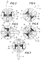
- Fig. 3 bis 7
- verschiedene Kurbelwinkelstellungen dieses Getriebes im Funktionsschema
- Fig. 1 and 2
- an embodiment of a crank mechanism according to the invention in front view with the crank cover removed or in axial section along the line II-II of FIG. 1 and
- 3 to 7
- different crank angle positions of this transmission in the functional diagram
Ein Kurbeltrieb 1 besteht aus einer drehbar in einem Gehäuse 2 gelagerten Kurbelwelle 3 und einer Kurbel 4, die sich aus einer drehfest an der Kurbelwelle 3 angesetzten Kurbelwange 5 und einem in der Kurbelwange 5 radialverschiebbar geführten Kurbelarm 6 zusammensetzt.A
Um die Radialkomponente der Hubkraft für das Nutzmoment wirksam machen zu können, gibt es ein Zwischengetriebe 7, das ein Paar kurbelarmfeste und gegengleich ausgerichtete Zahnstangen 8, ein drehfest im Gehäuse 2 eingesetztes, zur Kurbelwelle 3 koaxiales Stützrad 9 sowie ein in der Kurbelwange 5 drehbar gelagertes Paar Übertragungsräder 10 und jeweils mit diesen drehfest verbundene, koaxiale Zahnsegmente 11 umfaßt. Das Stützrad 9, die Übertragungsräder 10 und die Zahnsegmente 11 weisen gleiche Teilkreisdurchmesser ihrer Verzahnungen auf und ihre Achsen liegen in einer gemeinsamen, normal zum Zahnstangenpaar 8 verlaufenden Ebene 12, wobei nun das Übertragungsräderpaar 10 ständig mit dem Stützrad 9 kämmt und die Zahnsegmente 11 jeweils abwechselnd mit den zugehörigen Zahnstangen 8 im Eingriff stehen. Die Zahnsegmente 11 besitzen jeweils an eine Vierteldrehung angepaßte Verzahnungsabschnitte 11a (in der Zeichnung sind das wegen der großen Zahnteilung jeweils nur 2 Zähne) und jedes Zahnsegment 11 weist zwei solche einander diametral gegenüberliegende Verzahnungsabschnitte 11a auf, so daß ein Hub des Kurbelarmes 6 innerhalb einer Vierteldrehung der Kurbelwange 5 erfolgt.In order to be able to make the radial component of the lifting force effective for the useful torque, there is an
Der Kurbelarm 6 nimmt im oberen Totpunkt der Kurbelbewegung seine äußerste Radialstellung ein, in der eine auf den Kurbelarm wirkende Hubkraft als reine Radialkomponente ohne Tangentialkomponente auftritt. Diese Radialkomponente wirkt über das Zahnstangenpaar 8 auf die Zahnsegmente 11, wobei zeichnungsgemäß die rechte Zahnstange 8 bei der beginnenden Abwärtsbewegung mit dem einen Verzahnungsabschnitt 11a des rechten Zahnsegmentes 11 in Eingriff kommt, während gleichzeitig einer der Verzahnungsabschnitte des linken Zahnsegmentes mit der linken Zahnstange außer Eingriff kommt (Fig.3). Dadurch kann der Kurbelarm 6 relativ zur Kurbelwange 5 abwärts bewegt werden, so daß über das rechte Zahnsegment 11 das rechte Übertragungsrad 10 verdreht wird und sich auf Grund des Eingriffes dieses Übertagungsrades mit dem feststehenden Stützrad 9 eine Abwälzbewegung und damit eine Drehbewegung im Uhrzeigersinn der Kurbelwange 5 und damit der Kurbelwelle 3 ergibt. Während des Eingriffes zwischen rechter Zahnstange 8 und rechtem Zahnsegment 11 laufen die linke Zahnstange und das linke Zahnsegment wegen des hier fehlenden Verzahnungsabschnittes eingriffsfreinebeneinander (Fig. 4).The
Erreicht der Kurbelarm 6 nach einer Vierteldrehung seine innerste Radialstellung (Fig. 5) sind die Zahnsegmente 11 soweit verdreht, daß das rechte Zahnsegment, jetzt das untere, den Eingriff mit der zugehörenden Zahnstange 8 verliert und das linke Zahnsegment, jetzt das obere, mit seinem entsprechenden Verzahnungsabschnitt 11a mit der oberen Zahnstange 8 in Eingriff kommt. Die nun beginnende Auswärts-Hubbewegung des Kurbelarmes 6 führt daher zu einer Verdrehung des oberen Zahnsegmentes wiederum im Uhrzeigersinn, während das untere Zahnsegment eingriffslos weiterdreht, und das obere Zahnsegment wirkt über das zugehörige Übertragungsrad 10, das am Stützrad 9 abläuft, ebenfalls drehantreibend auf die Kurbelwange 5 und die Kurbelwelle 3 (Fig. 6).If the
Im unteren Totpunkt, also nach einer halben Drehung, nimmt der Kurbelarm 6 wieder seine äußerste Radialstellung ein und das Zwischengetriebe 7 wiederholt seinen Bewegungsablauf wie bei der Kurbelbewegung vom oberen Totpunkt aus, nur daß nun die Zahnsegmente 11 die jeweils anderen Verzahnungsabschnitten 11a zum Einsatz bringen.At bottom dead center, ie after half a turn, the
Um den heiklen Vorgang der Hubbewegungsumkehr und des dabei ablaufenden Eingriffswechsels zwischen den Zahnsegmenten und den Zahnstangen einwandfrei abwickeln zu können, sind nicht weiter dargestellte Hubbegrenzungsanschläge und Führungen vorgesehen, die die Gefahr eines beidseitigen Eingriffsverlustes und damit einer Funktionsstörung bannen.In order to be able to handle the delicate process of the reversal of the stroke movement and the change of engagement between the toothed segments and the toothed racks properly, stroke limit stops and guides, not shown, are provided, which prevent the risk of loss of engagement on both sides and thus a malfunction.
Während der Kurbelbewegung vom oberen Totpunkt bis zu einem 90°igen Kurbelwinkel nimmt also die radiale Länge des Kurbelarmes von einem Maximum bis zu einem Minimum ab, wobei gleichzeitig die Radialkomponente der Hubkraft von einem Maximum auf ein Minimum ab- und die entsprechende Tangentialkomponente von einem Minimum auf ein Maximum zunimmt. Von dieser 90°igen Kurbelwinkellage bis zum unteren Totpunkt verlängert sich dann wieder der Kurbelarm, die Radialkomponente nimmt erneut zu und die Tangentialkomponente ab, wobei sich dieser Zyklus im Kurbelwinkelbereich von 180-360°, also vom unteren Totpunkt zurück zum oberen Totpunkt genauso fortsetzt usw.. Die auftretenden Hubkraftkomponenten sind nun, unabhängig davon, ob sie in den Extremlagen des oberen und unteren Totpunktes und der 90° und 270°igen Kurbelwinkellage jeweils allein oder in den Zwischenlagen gemeinsam auftreten, stets im möglichen Ausmaß für das abnehmbare Nutzmoment wirksam, und zwar die Tangentialkomponente direkt über den Kurbelarm selbst und die Radialkomponente indirekt über Kurbelarm und Zwischengetriebe, so daß sich zumindest theoretisch eine verlustfreie Umwandlung von Hubbewegung und Drehbewegung ergibt.During the crank movement from top dead center to a 90 ° crank angle, the radial length of the crank arm decreases from a maximum to a minimum, with the radial component of the lifting force decreasing from a maximum to a minimum and the corresponding tangential component from a minimum increases to a maximum. From this 90 ° crank angle to bottom dead center, the crank arm is extended again, the radial component increases again and the tangential component decreases, whereby this cycle continues in the crank angle range of 180-360 °, i.e. from bottom dead center back to top dead center, and so on .. The occurring lifting force components are now, regardless of whether they occur in the extreme positions of the top and bottom dead center and the 90 ° and 270 ° crank angle position alone or in the intermediate positions, always effective to the extent possible for the removable useful torque, and the tangential component directly via the crank arm itself and the radial component indirectly via the crank arm and intermediate gear, so that, at least theoretically, there is a lossless conversion of the lifting movement and the rotary movement.
Claims (3)
- Crank mechanism (1) with a rotary crankshaft (3) run on bearings in a crankcase or equiv. and a crank consisting of a crank web (5) with non-rotary attachment to the crankshaft (3) and guided radial sliding crank arm (6) in the crank web (5) where in order to convert the lifting motion of the crank arm into a rotary motion of the crankshaft, an intermediate gear (7) with a rack (8) arranged on the crank arm (6) in the lifting direction and corresponding toothed transmission and support wheels (9, 10) assigned to either the crank web (5) or the case and lifting motions in accordance with alternately acting toothed segments (11) are provided, distinguished by the fact that the extreme radial position of the crank arm (6) is in the area of the upper dead centre of the crank motion and that the intermediate gear (7) comprises a pair of parallel, diametrically opposed racks (8) fixed to the crank arm, a support wheel (9) coaxial to the crankshaft (3) and fixed to the case, and a pair of pivoted transmission wheels (10) situated in the crank web (5) and coaxial toothed segments (11) with non-rotary attachment to these, where the support wheel (9), the transmission wheels (10) and the toothed segments (11) have the same gearing reference diameter and lie with their axes in a common plane (12) normally running to the rack pair (8) and where on the one hand there is constant meshing between the transmission wheel pair (10) and the support wheel (9) and on the other hand alternate meshing between the toothed segments (11) and the rack pair (8).
- Crank mechanism in accordance with claim 1, distinguished by the fact that the gearing sections (11a) of the toothed segments (11) are each adjusted to a quarter turn and the toothed segments (11) each have two diametrically opposed gearing sections (11a).
- Crank mechanism in accordance with claim 1 or 2, distinguished by the fact that the transmission wheels (10) form a unit with the relevant toothed segments (11) in each case.
Applications Claiming Priority (2)
| Application Number | Priority Date | Filing Date | Title |
|---|---|---|---|
| AT1131/90 | 1990-05-22 | ||
| AT113190 | 1990-05-22 |
Publications (2)
| Publication Number | Publication Date |
|---|---|
| EP0462099A1 EP0462099A1 (en) | 1991-12-18 |
| EP0462099B1 true EP0462099B1 (en) | 1994-07-13 |
Family
ID=3507269
Family Applications (1)
| Application Number | Title | Priority Date | Filing Date |
|---|---|---|---|
| EP19910890105 Expired - Lifetime EP0462099B1 (en) | 1990-05-22 | 1991-05-15 | Crank drive |
Country Status (2)
| Country | Link |
|---|---|
| EP (1) | EP0462099B1 (en) |
| DE (1) | DE59102157D1 (en) |
Families Citing this family (8)
| Publication number | Priority date | Publication date | Assignee | Title |
|---|---|---|---|---|
| JPH0754829A (en) * | 1993-06-01 | 1995-02-28 | Sokan Shu | Crank device |
| KR100386851B1 (en) * | 1999-12-30 | 2003-06-09 | 강병남 | Adjustable crank shaft of bike |
| KR100382699B1 (en) * | 2000-05-03 | 2003-05-09 | 정선국 | Pedal driving device |
| CN102562998B (en) * | 2012-02-17 | 2014-07-23 | 安里千 | Gear-tooth block meshing switching device for linear reciprocating motion and rotational motion |
| JP6022407B2 (en) * | 2013-06-04 | 2016-11-09 | 本田技研工業株式会社 | Power transmission device |
| JP6014554B2 (en) * | 2013-06-05 | 2016-10-25 | 本田技研工業株式会社 | Power transmission device |
| CN103498899B (en) * | 2013-10-18 | 2016-08-24 | 苏州大学 | Electronic both hands rub bionic device |
| CN103498897B (en) * | 2013-10-18 | 2016-08-24 | 苏州大学 | Electronic both hands rub bionic device |
Family Cites Families (2)
| Publication number | Priority date | Publication date | Assignee | Title |
|---|---|---|---|---|
| CH605241A5 (en) * | 1976-06-28 | 1978-09-29 | Berclaz Rene Louis | |
| US4800768A (en) * | 1987-05-07 | 1989-01-31 | 4N Developments Ltd. | Power transmission apparatus |
-
1991
- 1991-05-15 EP EP19910890105 patent/EP0462099B1/en not_active Expired - Lifetime
- 1991-05-15 DE DE59102157T patent/DE59102157D1/en not_active Expired - Fee Related
Also Published As
| Publication number | Publication date |
|---|---|
| DE59102157D1 (en) | 1994-08-18 |
| EP0462099A1 (en) | 1991-12-18 |
Similar Documents
| Publication | Publication Date | Title |
|---|---|---|
| EP0462099B1 (en) | Crank drive | |
| DE60012618T2 (en) | Adjustment device for the outside diameter of a folding cylinder | |
| DE69017106T2 (en) | Gear transmission with high efficiency. | |
| DE2934874C2 (en) | ||
| DE1182011B (en) | Gearbox with several toothed wheels | |
| AT398817B (en) | Crank mechanism | |
| DE2202056C3 (en) | Device for preventing a measurement error in a length measuring device | |
| DE520417C (en) | Rack and pinion gear for converting a straight back and forth movement into a continuous rotary movement | |
| DE3130314C2 (en) | ||
| DE10021237C2 (en) | Reduction gear with a wave generator formed by planet gears | |
| WO1994011651A1 (en) | Epicyclic roller gear with two rings having an inner profile and a rolling element capable of rolling on the outer side of the rings | |
| CH681248A5 (en) | ||
| DE2357236C2 (en) | Switching device for change gears of motor vehicles | |
| EP0204275B1 (en) | Driving device, in particular for bicycles | |
| DE102007044162A1 (en) | Reciprocating piston engine, particularly motor, has reciprocating piston, which is connected with gear rod, which work together with assigned gear wheel arrangement | |
| DE2130781B2 (en) | Multiple drive for a gear rim, with several carriers for the drive pinions | |
| DE10349489B3 (en) | Pipe bending machine has a horizontal drive with a conical gear wheel in contact with a ring gear | |
| DE19923426B4 (en) | transmission | |
| DE2159372C3 (en) | One-way clutch | |
| DE2051127A1 (en) | Seat, in particular motor vehicle seat | |
| DE20315691U1 (en) | Hub control gear with foot pedal for use in bicycles, comprises a rotary hub shaft housed in the hub sleeve, and has hollow shaft which carries the sun wheel, and which is connected to hub sleeve via a free-wheel clutch | |
| CH696038A5 (en) | Linear gear consists of shaft with connecting rod and gear rim that is firmly connected to a planet wheel to which a planet gear wheel is connected | |
| DE399578C (en) | Epicyclic gear change and reversing gear housed in an engine flywheel | |
| DE3801597C2 (en) | ||
| DE278166C (en) |
Legal Events
| Date | Code | Title | Description |
|---|---|---|---|
| PUAI | Public reference made under article 153(3) epc to a published international application that has entered the european phase |
Free format text: ORIGINAL CODE: 0009012 |
|
| AK | Designated contracting states |
Kind code of ref document: A1 Designated state(s): BE CH DE DK ES FR GB GR IT LI LU NL SE |
|
| 17P | Request for examination filed |
Effective date: 19920306 |
|
| 17Q | First examination report despatched |
Effective date: 19930930 |
|
| GRAA | (expected) grant |
Free format text: ORIGINAL CODE: 0009210 |
|
| AK | Designated contracting states |
Kind code of ref document: B1 Designated state(s): BE CH DE DK ES FR GB GR IT LI LU NL SE |
|
| PG25 | Lapsed in a contracting state [announced via postgrant information from national office to epo] |
Ref country code: IT Free format text: LAPSE BECAUSE OF FAILURE TO SUBMIT A TRANSLATION OF THE DESCRIPTION OR TO PAY THE FEE WITHIN THE PRE;WARNING: LAPSES OF ITALIAN PATENTS WITH EFFECTIVE DATE BEFORE 2007 MAY HAVE OCCURRED AT ANY TIME BEFORE 2007. THE CORRECT EFFECTIVE DATE MAY BE DIFFERENT FROM THE ONE RECORDED.SCRIBED TIME-LIMIT Effective date: 19940713 Ref country code: BE Effective date: 19940713 Ref country code: GR Free format text: LAPSE BECAUSE OF FAILURE TO SUBMIT A TRANSLATION OF THE DESCRIPTION OR TO PAY THE FEE WITHIN THE PRESCRIBED TIME-LIMIT Effective date: 19940713 Ref country code: NL Effective date: 19940713 Ref country code: GB Effective date: 19940713 Ref country code: FR Effective date: 19940713 Ref country code: DK Effective date: 19940713 Ref country code: ES Free format text: THE PATENT HAS BEEN ANNULLED BY A DECISION OF A NATIONAL AUTHORITY Effective date: 19940713 |
|
| REF | Corresponds to: |
Ref document number: 59102157 Country of ref document: DE Date of ref document: 19940818 |
|
| PG25 | Lapsed in a contracting state [announced via postgrant information from national office to epo] |
Ref country code: SE Effective date: 19941013 |
|
| EN | Fr: translation not filed | ||
| NLV1 | Nl: lapsed or annulled due to failure to fulfill the requirements of art. 29p and 29m of the patents act | ||
| GBV | Gb: ep patent (uk) treated as always having been void in accordance with gb section 77(7)/1977 [no translation filed] |
Effective date: 19941013 |
|
| GBV | Gb: ep patent (uk) treated as always having been void in accordance with gb section 77(7)/1977 [no translation filed] |
Effective date: 19940713 |
|
| GBV | Gb: ep patent (uk) treated as always having been void in accordance with gb section 77(7)/1977 [no translation filed] |
Free format text: DATE CORRECTED TO 940713 |
|
| PLBE | No opposition filed within time limit |
Free format text: ORIGINAL CODE: 0009261 |
|
| STAA | Information on the status of an ep patent application or granted ep patent |
Free format text: STATUS: NO OPPOSITION FILED WITHIN TIME LIMIT |
|
| PG25 | Lapsed in a contracting state [announced via postgrant information from national office to epo] |
Ref country code: LU Free format text: LAPSE BECAUSE OF NON-PAYMENT OF DUE FEES Effective date: 19950531 |
|
| 26N | No opposition filed | ||
| PGFP | Annual fee paid to national office [announced via postgrant information from national office to epo] |
Ref country code: DE Payment date: 20040610 Year of fee payment: 14 |
|
| PG25 | Lapsed in a contracting state [announced via postgrant information from national office to epo] |
Ref country code: DE Free format text: LAPSE BECAUSE OF NON-PAYMENT OF DUE FEES Effective date: 20051201 |
|
| PGFP | Annual fee paid to national office [announced via postgrant information from national office to epo] |
Ref country code: CH Payment date: 20100625 Year of fee payment: 20 |
|
| REG | Reference to a national code |
Ref country code: CH Ref legal event code: PL |