EP0462088A2 - Femoral compression device - Google Patents
Femoral compression device Download PDFInfo
- Publication number
- EP0462088A2 EP0462088A2 EP91850144A EP91850144A EP0462088A2 EP 0462088 A2 EP0462088 A2 EP 0462088A2 EP 91850144 A EP91850144 A EP 91850144A EP 91850144 A EP91850144 A EP 91850144A EP 0462088 A2 EP0462088 A2 EP 0462088A2
- Authority
- EP
- European Patent Office
- Prior art keywords
- pressure
- femoral
- pressurizing means
- compression device
- base plate
- Prior art date
- Legal status (The legal status is an assumption and is not a legal conclusion. Google has not performed a legal analysis and makes no representation as to the accuracy of the status listed.)
- Granted
Links
- 230000006835 compression Effects 0.000 title claims abstract description 33
- 238000007906 compression Methods 0.000 title claims abstract description 33
- 210000001105 femoral artery Anatomy 0.000 claims abstract description 19
- 230000000740 bleeding effect Effects 0.000 claims abstract description 7
- 230000010349 pulsation Effects 0.000 claims description 20
- 210000001367 artery Anatomy 0.000 claims description 17
- 238000000034 method Methods 0.000 claims description 17
- 230000036772 blood pressure Effects 0.000 claims description 16
- 230000001419 dependent effect Effects 0.000 claims description 10
- 230000023597 hemostasis Effects 0.000 claims description 10
- 238000012544 monitoring process Methods 0.000 claims description 7
- 230000035488 systolic blood pressure Effects 0.000 claims description 7
- 239000004033 plastic Substances 0.000 claims description 5
- 230000035487 diastolic blood pressure Effects 0.000 claims description 4
- 238000003780 insertion Methods 0.000 claims description 2
- 230000037431 insertion Effects 0.000 claims description 2
- 239000000203 mixture Substances 0.000 claims description 2
- 230000002035 prolonged effect Effects 0.000 claims description 2
- 239000012780 transparent material Substances 0.000 claims description 2
- 230000017531 blood circulation Effects 0.000 abstract description 14
- 230000003205 diastolic effect Effects 0.000 abstract 1
- 208000032843 Hemorrhage Diseases 0.000 description 5
- 230000001105 regulatory effect Effects 0.000 description 3
- HTTJABKRGRZYRN-UHFFFAOYSA-N Heparin Chemical compound OC1C(NC(=O)C)C(O)OC(COS(O)(=O)=O)C1OC1C(OS(O)(=O)=O)C(O)C(OC2C(C(OS(O)(=O)=O)C(OC3C(C(O)C(O)C(O3)C(O)=O)OS(O)(=O)=O)C(CO)O2)NS(O)(=O)=O)C(C(O)=O)O1 HTTJABKRGRZYRN-UHFFFAOYSA-N 0.000 description 2
- 239000008280 blood Substances 0.000 description 2
- 210000004369 blood Anatomy 0.000 description 2
- 239000002872 contrast media Substances 0.000 description 2
- 230000001276 controlling effect Effects 0.000 description 2
- 210000004013 groin Anatomy 0.000 description 2
- 229960002897 heparin Drugs 0.000 description 2
- 229920000669 heparin Polymers 0.000 description 2
- 238000011835 investigation Methods 0.000 description 2
- 230000000474 nursing effect Effects 0.000 description 2
- 229920002799 BoPET Polymers 0.000 description 1
- 206010018852 Haematoma Diseases 0.000 description 1
- 208000031481 Pathologic Constriction Diseases 0.000 description 1
- 208000007536 Thrombosis Diseases 0.000 description 1
- 239000003146 anticoagulant agent Substances 0.000 description 1
- 210000004204 blood vessel Anatomy 0.000 description 1
- 238000010276 construction Methods 0.000 description 1
- 230000003247 decreasing effect Effects 0.000 description 1
- 238000013461 design Methods 0.000 description 1
- 230000000694 effects Effects 0.000 description 1
- 239000004744 fabric Substances 0.000 description 1
- 239000002874 hemostatic agent Substances 0.000 description 1
- 239000000463 material Substances 0.000 description 1
- 239000002184 metal Substances 0.000 description 1
- 238000012986 modification Methods 0.000 description 1
- 230000004048 modification Effects 0.000 description 1
- 230000036262 stenosis Effects 0.000 description 1
- 208000037804 stenosis Diseases 0.000 description 1
- 230000000007 visual effect Effects 0.000 description 1
Images

Classifications
-
- A—HUMAN NECESSITIES
- A61—MEDICAL OR VETERINARY SCIENCE; HYGIENE
- A61B—DIAGNOSIS; SURGERY; IDENTIFICATION
- A61B17/00—Surgical instruments, devices or methods
- A61B17/12—Surgical instruments, devices or methods for ligaturing or otherwise compressing tubular parts of the body, e.g. blood vessels or umbilical cord
- A61B17/132—Tourniquets
- A61B17/1322—Tourniquets comprising a flexible encircling member
- A61B17/1325—Tourniquets comprising a flexible encircling member with means for applying local pressure
-
- A—HUMAN NECESSITIES
- A61—MEDICAL OR VETERINARY SCIENCE; HYGIENE
- A61B—DIAGNOSIS; SURGERY; IDENTIFICATION
- A61B17/00—Surgical instruments, devices or methods
- A61B17/12—Surgical instruments, devices or methods for ligaturing or otherwise compressing tubular parts of the body, e.g. blood vessels or umbilical cord
- A61B17/132—Tourniquets
- A61B17/135—Tourniquets inflatable
Definitions
- the present invention relates to a femoral compression device comprising a pressurizing means to bear on the femoral artery and a method for hemostasis of the femoral artery following, for example, catheterisation.
- the catheter is drawn out and the bleeding from the incision site in the femoral artery is stopped.
- This can be done manually, ie the physian presses the finger against a compressive bandage laid on the wound for about 20 minutes. Obviously this is not a satisfactory method since it is inconvenient for both patients and physians and also require valuble physian time. Furthermore, it is difficult for the physian to maintain a constant pressure force.
- US A 4 509 528 describes an hemostat with blood flow sensor.
- the sensor 21 measures the blood flow and can be of, for example, Doppler type.
- the signal from the sensor is processed by a signal processor 24 producing a second signal, preferably a sound, varying in volume in response to changes in the blood flow through the blood vessel.
- a signal processor 24 producing a second signal, preferably a sound, varying in volume in response to changes in the blood flow through the blood vessel.
- US 4 770 175 describes a device for occluding blood flow into a digit and not to regulate the same.
- the device is provided with a pressurizing means 20 and a sensor sensing the pressure excerted by the means 20 against the digit.
- the signal from the sensor is digitally processed and thereafter a signal goes to the pressurizing means in such a way that a constant, occluding pressure always acts on the digit.
- the device does not comprise a sensor measuring blood flow.
- the shown Doppler device 64 is only used to obtain standard curves to establish occluding pressure levels for different cuff and digit dimensions.
- the principle of these devices is the same, ie that a pressure is applied on the incision site in the femoral artery for about 20 minutes following completed catheterisation.
- the pressure is to be set as high as possible to stop bleeding but not as high that the blood flow down to the leg and foot is cut off.
- the object of the present invention was to provide a femoral compression device which is more reliable than and avoids the disadvantages of prior art.
- Another object was to provide a device which is more comfortable and gives greater freedom of movement for the patients.
- a femoral compression device according to the characterizing part of claim 1 and a method for hemostasis of the femoral artery following, for example, heart catheterisation according to the characterizing part of claim 20 respectively.
- Fig. 1 shows a femoral compression device 1 comprising a pressurizing means 5 for compressive bearing at the puncture site, preferably located at the femoral artery of a patient subjected to, for example, heart catheterisation, and for applying a pressure on the same, and a base plate 2 for supporting said pressurizing means.
- the device 1 comprises a belt 3 adapted to be fixed around the patient's body.
- the base plate 2 has a top portion and a bottom portion and is adapted to be fixed to the belt 3.
- the pressurizing means 5 is provided at the bottom portion of the base plate 2 so as to excert a compressive force against the patient's body at the puncture site.
- the base plate 2 can be integrated with the belt 3 as shown in Fig. 1.
- the base plate 2 is made of hard plastic or metal and is intended to be secured over the femoral puncture site of the treated patient by the flexible belt 3 enclosing the body of the patient at the hip area.
- the belt 3 is locked by a locking device 4; in the shown embodiment this is of Velcro® tape.
- the pressurizing means 5 is pressure tight arranged being in the form of a semi spherical balloon.
- the balloon 5 is preferably made of a soft plastic, elastomere or mixture thereof and is optionally reinforced, eg with fabric.
- the material of the balloon should have maximum flexibility and minimum creep.
- the plastic can be of PVC being easily resilient with a constant inner overpressure, or of Mylar® film being only slightly resilient with a constant inner overpressure.
- the base plate is circular but it can of course also take other forms, eg square, rectangular or oval.
- a connection 6 is arranged for inflating the balloon 5.
- the balloon and a part of or the whole base plate 2 are made of transparent material.
- the base plate 2 can be integrated in the belt 3 or form a separate unit.
- Fig. 2 shows a preferred embodiment of the present invention.
- the top portion of the base plate 2 comprises extension means 2a, 2b extending in opposite directions and being provided with locking means 4 in the ends thereof for insertion of a respective end of the belt 3.
- the extension 2a is shorter than the extension 2b, the extensions preferably being arc shaped and disposed at an elevated position in relation the base plate 2.
- a balloon 5 is fastened in the bottom side of the base plate 2 in the same manner as in Fig. 1.
- a belt 3 is fastened in the outer ends of the extensions 2a, 2b by a self locking device 4 having a greater width than the extensions 2a, 2b.
- the width of the locking means generally corresponds to the width of belt 3 being broad to compensate for imbalance of the device. Imbalance is also compensated for by the extended shape of the base plate 2 in that it gives the balloon 5 a stable base. This embodiment is especially comfortable for the patient as it allows some movement of the patient without changing the balloon position. Furthermore the device can be left on the patient after completed hemostasis instead of a conventional compressive bandage. In this figure there is also shown a tubing 6a connecting the connection 6 to a pump 7 having a pressure gauge 8.
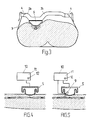
- the cross section according to Fig. 3 shows the device according to Fig. 2 mounted on a patient.
- the arc shaped extensions 2a, 2b provide clearance beneath the device, and this design makes the device more comfortable for fat patients.
- the short extension 2a is to be put on the artery side of the patient and the longer extension 2b on the other side of the patient.
- the base plate 2 is telescopically designed enabling it to be adjusted to different body widths.
- the pressurizing means 5 can also be designed as a truncated cone to decrease the pressure surface against the body. To obtain an even more selective pressure on a small surface the pressure surface is provided as a stiff portion, for example ten times thicker than the rest of the pressurizing means 5. This latter embodiment will function as a pneumatic air cylinder.
- the pressurizing means can be provided with accordion foldings in the upper portion closest to the base plate 2 to increase the effective stroke length thereof. This also eliminates the risk that the partially inflated balloon will be folded at the pressure surface against the skin, which at continued expansion of the balloon results in friction and therefore possible discomfort for the patient.
- the balloon 5 is laid against the puncture site and tightened against this by tightening the belt 3 and securing it by the locking device 4.
- the balloon 5 is inflated by the pump 7 via the connection 6 and tubing 6a to a pressure being at a determined value between the diastolic and systolic pressure level read on the pressure gauge 8.
- a tissue pressure is excerted about the artery being slightly lower than the systolic pressure which results in maintaining the correct blood flow.
- the inflation of the balloon 5 can be done manually like in Fig. 2 or automatically as decribed below.
- the blood flow down to the leg and foot can be registrated by measuring the pulse downstream of the puncture site. If the pressure is too low blood will ooze out of the puncture site which can be observed through the transparent balloon 5 and base plate 2.
- Fig. 4 shows the femoral compression device in assocation with an electronic control unit 10 comprising a driving means, such as a pump.
- the electronic control unit can be provided with a pressure gauge.
- This embodiment is constructed as an automatic regulating device in which selected pressure values and times etc. can be programmed into the electronic control unit 10 for sequentially applying different pressures on the artery. After about 20 minutes, for example, the initial hemostasis pressure must be decreased and the automatic regulating device gives extra security in case the nursing personell are absent at that time.
- the automatic regulating device also compensates for any creep relaxations in the plastic of the balloon 5 and any leakage in the system.
- the degree of inflation of the balloon 5 is controlled pnuematically or hydraulically via the driving means. Filling and emptying of the balloon 5 results in that the balloon is pressed against and from the puncture site, respectively.
- the method according to the invention for hemostasis of the femoral artery of a patient following, for example, heart catheterisation comprises the steps of: applying a reference pressure over the puncture site; applying an additional pressure over said puncture site; monitoring the sum of said reference pressure and said additional pressure; gradually reducing said additional pressure over a prolonged period of time; and releasing said reference pressure when said hemostasis is fully completed.
- the pulsations occur only between the systolic and diastolic pressure values. If no pulse can be registrated, indicating that the blood flow through the artery is too high or too low, the electronic control unit 10 triggers an alarm calling for the attention of the nursing personell. This embodiment guarantees that the balloon always is correctly positioned.
- the pulsations in the pressure medium of said pressurizing means 5 caused by the pulse of the patient are registrated and processed by said electronic control unit 10.
- the driving means is responsive to signals from said electronic control unit 10 in such a way that the selected pressure value is constantly maintained or updated dependent on the registrated pulsation value.
- this embodiment provides a feed back from the pressurizing means to the electronic control unit.
- the monitoring step further comprises registration of pulsation values caused by the patients pulse at said puncture site and comparing said pulsation values with selected values and controlling said additional pressure dependent on said registrated pulsation values.
- an external sensor 9 disposed at or downstream of the compression site detects actual blood pressure in the artery and reports the detected actual blood pressure values to the electronic control unit 10 for comparison with a selected pressure value.
- the driving means is responsive to signals from the electronic control unit 10 in such a way that the selected pressure value is constantly maintained or updated dependent on the detected actual blood pressure value.
- the monitoring step further comprises registration of actual blood pressure values at or downstream of said puncture site and comparing said actual blood pressure values with selected values and controlling said additional pressure dependent on said registrated actual blood pressure values.
- the position of the sensor 9 is not critical but should be at or downstream of the actual press site; naturally it need not be disposed within the pressurizing means 5 but can also be arranged separetely. Data from the sensor 9 can be read on a monitor 11 which is also provided with speakers (not shown) alarming if the flow is too high because the pressurizing means 5 has been moved out of position. The flow can also be adjusted manually in emergency cases by an adjusting wheel 12 on the monitor 11.
- the sensor 9 can be a microphone detecting the Korotkoff-sound, ie the sound created by turbulence in arteries when the applied pressure is between the systolic and diastolic pressure levels of the patient, or an ultrasonic Doppler detecting the blood flow.
- sensors for measuring blood flow such as the Doppler devices existing today, cannot be used to satisfactorily perform hemostasis of the femoral artery because of its deep position and the low blood flows therein.
- the pressurizing means 5 When setting the pressurizing means 5 against the compression site, ie the groin skin and underlaying femoral artery, it is pushed downwardly until the sensor 9 detects the systolic pressure level, ie the Korotkoff-sound. Thereafter the electronics regulates the applied pressure to a determined value under the systolic pressure in a certain number of percent units. This pressure level is updated or maintained constantly and the method according to the invention regulates independently of the absolute pressure values of the patient.
- an optic sensor (not shown) which senses if bleeding starts and sends signals to the electronic control unit 10.
- the reflectance from the skin is detected by a light source and a detector.
- the optic sensor operates at two wave lengths, one that detects blood on the skin, and another that detects if the patient becomes blue as a result of a bleedning beneath the skin. Any colour changes of the skin results in an alarm sound in the speakers being controlled by the electronic control unit 10.
Landscapes
- Health & Medical Sciences (AREA)
- Surgery (AREA)
- Life Sciences & Earth Sciences (AREA)
- Heart & Thoracic Surgery (AREA)
- Nuclear Medicine, Radiotherapy & Molecular Imaging (AREA)
- Vascular Medicine (AREA)
- Engineering & Computer Science (AREA)
- Biomedical Technology (AREA)
- Reproductive Health (AREA)
- Medical Informatics (AREA)
- Molecular Biology (AREA)
- Animal Behavior & Ethology (AREA)
- General Health & Medical Sciences (AREA)
- Public Health (AREA)
- Veterinary Medicine (AREA)
- Surgical Instruments (AREA)
Abstract
Description
- The present invention relates to a femoral compression device comprising a pressurizing means to bear on the femoral artery and a method for hemostasis of the femoral artery following, for example, catheterisation.
- To be able to visualize arteries and venes with contrast medium during, for example, heart catheterisation and angiograpfy, one oftens enters via the femoralis artery in the groin. Investigations via the femoral artery are especially difficult because of the high pressure against the artery wall. Today an invstigation like that is performed in that a small incision is made in the femoral artery using a small diameter cannula. A guide is inserted into the canulla and into the artery and thereafter a catheter is threaded over the guide into the artery. Thereafter the guide is removed and contrast medium is injected through the catheter into the artery.
- After completed investigation the catheter is drawn out and the bleeding from the incision site in the femoral artery is stopped. This can be done manually, ie the physian presses the finger against a compressive bandage laid on the wound for about 20 minutes. Obviously this is not a satisfactory method since it is inconvenient for both patients and physians and also require valuble physian time. Furthermore, it is difficult for the physian to maintain a constant pressure force.
- Several devices have also been proposed by which a pressure is applied onto the wound in the femoral artery.
- US A 4 509 528 describes an hemostat with blood flow sensor. The sensor 21 measures the blood flow and can be of, for example, Doppler type. The signal from the sensor is processed by a signal processor 24 producing a second signal, preferably a sound, varying in volume in response to changes in the blood flow through the blood vessel. This arrangement is well known and desribed earlier. When the sound, and thus also the blood flow, varies the latter is to be reset manually by a number of adjustments. Thus there exist no feed back from the sensor to the operating means.
- US 4 770 175 describes a device for occluding blood flow into a digit and not to regulate the same. The device is provided with a pressurizing means 20 and a sensor sensing the pressure excerted by the means 20 against the digit. The signal from the sensor is digitally processed and thereafter a signal goes to the pressurizing means in such a way that a constant, occluding pressure always acts on the digit. Thus the device does not comprise a sensor measuring blood flow. The shown Doppler device 64 is only used to obtain standard curves to establish occluding pressure levels for different cuff and digit dimensions.
- In US 3 625 219 there is shown a device for hemostasis in which an inflatable balloon is used as pressurizing means. However this device involves a complex and instable construction and does not allow patient movement. Like the above devices, this one does not comprise a feed back from the sensor to the pressurizing means.
- The principle of these devices is the same, ie that a pressure is applied on the incision site in the femoral artery for about 20 minutes following completed catheterisation. The pressure is to be set as high as possible to stop bleeding but not as high that the blood flow down to the leg and foot is cut off.
- Following ballon dilatation of the femoral artery in the leg it is especially important not to apply too high pressure on the incision site as there is a risk that the dilated stenosis in the artery will contract if the blood pressure is too low. To avoid blood clots the patients are given anti coagulating agents, such as heparin, prior to the treatment. This of course extends the time required to stop the bleeding after having completed the method. For patients already taking heparin of medical reasons, the time will be as long as up to 1,5 hours. Hematoma is the most common side effect due to insufficient compression of the femoral artery.
- Therefore the object of the present invention was to provide a femoral compression device which is more reliable than and avoids the disadvantages of prior art.
- Another object was to provide a device which is more comfortable and gives greater freedom of movement for the patients.
- These objects are achieved by a femoral compression device according to the characterizing part of claim 1 and a method for hemostasis of the femoral artery following, for example, heart catheterisation according to the characterizing part of claim 20 respectively.
- The invention will now be described with further detail below with reference to the accompanying drawings, in which
- Fig. 1 is a schematic view of the femoral compression device according to the invention;
- Fig. 2 shows an alternative embodiment of the femoral compression device;
- Fig. 3 is a section view of the femoral compression device according to Fig. 2 applied on a patient;
- Fig. 4 is a schematic view of femoral compression device comprising an electronic control unit; and
- Fig. 5 is a schematic view of femoral compression device comprising an electronic control unit and a sensor.
- Fig. 1 shows a femoral compression device 1 comprising a
pressurizing means 5 for compressive bearing at the puncture site, preferably located at the femoral artery of a patient subjected to, for example, heart catheterisation, and for applying a pressure on the same, and abase plate 2 for supporting said pressurizing means. The device 1 comprises abelt 3 adapted to be fixed around the patient's body. Thebase plate 2 has a top portion and a bottom portion and is adapted to be fixed to thebelt 3. Thepressurizing means 5 is provided at the bottom portion of thebase plate 2 so as to excert a compressive force against the patient's body at the puncture site. Thebase plate 2 can be integrated with thebelt 3 as shown in Fig. 1. Thebase plate 2 is made of hard plastic or metal and is intended to be secured over the femoral puncture site of the treated patient by theflexible belt 3 enclosing the body of the patient at the hip area. Thebelt 3 is locked by alocking device 4; in the shown embodiment this is of Velcro® tape. On the lower side of thebase plate 2 the pressurizingmeans 5 is pressure tight arranged being in the form of a semi spherical balloon. Theballoon 5 is preferably made of a soft plastic, elastomere or mixture thereof and is optionally reinforced, eg with fabric. The material of the balloon should have maximum flexibility and minimum creep. The plastic can be of PVC being easily resilient with a constant inner overpressure, or of Mylar® film being only slightly resilient with a constant inner overpressure. In the shown embodiment the base plate is circular but it can of course also take other forms, eg square, rectangular or oval. In the top portion of thebase plate 2 aconnection 6 is arranged for inflating theballoon 5. To enable visual observation of bleeding, the balloon and a part of or thewhole base plate 2 are made of transparent material. Thebase plate 2 can be integrated in thebelt 3 or form a separate unit. - Fig. 2 shows a preferred embodiment of the present invention. The features that differ this embodiment from the above described is that the top portion of the
base plate 2 comprises extension means 2a, 2b extending in opposite directions and being provided with locking means 4 in the ends thereof for insertion of a respective end of thebelt 3. Theextension 2a is shorter than theextension 2b, the extensions preferably being arc shaped and disposed at an elevated position in relation thebase plate 2. Aballoon 5 is fastened in the bottom side of thebase plate 2 in the same manner as in Fig. 1. Abelt 3 is fastened in the outer ends of theextensions self locking device 4 having a greater width than theextensions belt 3 being broad to compensate for imbalance of the device. Imbalance is also compensated for by the extended shape of thebase plate 2 in that it gives the balloon 5 a stable base. This embodiment is especially comfortable for the patient as it allows some movement of the patient without changing the balloon position. Furthermore the device can be left on the patient after completed hemostasis instead of a conventional compressive bandage. In this figure there is also shown atubing 6a connecting theconnection 6 to apump 7 having a pressure gauge 8. - The cross section according to Fig. 3 shows the device according to Fig. 2 mounted on a patient. As appears the arc shaped
extensions short extension 2a is to be put on the artery side of the patient and thelonger extension 2b on the other side of the patient. Alternatively thebase plate 2 is telescopically designed enabling it to be adjusted to different body widths. - The pressurizing means 5 can also be designed as a truncated cone to decrease the pressure surface against the body. To obtain an even more selective pressure on a small surface the pressure surface is provided as a stiff portion, for example ten times thicker than the rest of the pressurizing means 5. This latter embodiment will function as a pneumatic air cylinder.
- Furthermore, the pressurizing means can be provided with accordion foldings in the upper portion closest to the
base plate 2 to increase the effective stroke length thereof. This also eliminates the risk that the partially inflated balloon will be folded at the pressure surface against the skin, which at continued expansion of the balloon results in friction and therefore possible discomfort for the patient. - Following completed catheterisation via the femoral artery, the
balloon 5 is laid against the puncture site and tightened against this by tightening thebelt 3 and securing it by thelocking device 4. Theballoon 5 is inflated by thepump 7 via theconnection 6 andtubing 6a to a pressure being at a determined value between the diastolic and systolic pressure level read on the pressure gauge 8. A tissue pressure is excerted about the artery being slightly lower than the systolic pressure which results in maintaining the correct blood flow. The inflation of theballoon 5 can be done manually like in Fig. 2 or automatically as decribed below. The blood flow down to the leg and foot can be registrated by measuring the pulse downstream of the puncture site. If the pressure is too low blood will ooze out of the puncture site which can be observed through thetransparent balloon 5 andbase plate 2. - Fig. 4 shows the femoral compression device in assocation with an
electronic control unit 10 comprising a driving means, such as a pump. Optionally the electronic control unit can be provided with a pressure gauge. This embodiment is constructed as an automatic regulating device in which selected pressure values and times etc. can be programmed into theelectronic control unit 10 for sequentially applying different pressures on the artery. After about 20 minutes, for example, the initial hemostasis pressure must be decreased and the automatic regulating device gives extra security in case the nursing personell are absent at that time. The automatic regulating device also compensates for any creep relaxations in the plastic of theballoon 5 and any leakage in the system. The degree of inflation of theballoon 5 is controlled pnuematically or hydraulically via the driving means. Filling and emptying of theballoon 5 results in that the balloon is pressed against and from the puncture site, respectively. - The method according to the invention for hemostasis of the femoral artery of a patient following, for example, heart catheterisation, comprises the steps of: applying a reference pressure over the puncture site; applying an additional pressure over said puncture site; monitoring the sum of said reference pressure and said additional pressure; gradually reducing said additional pressure over a prolonged period of time; and releasing said reference pressure when said hemostasis is fully completed.
- In an alternative embodiment one also registrates the pulsations of the pressure medium in the
balloon 5 being created by the pulse of the patient. The pulsations occur only between the systolic and diastolic pressure values. If no pulse can be registrated, indicating that the blood flow through the artery is too high or too low, theelectronic control unit 10 triggers an alarm calling for the attention of the nursing personell. This embodiment guarantees that the balloon always is correctly positioned. - In a modification of the above embodiment the pulsations in the pressure medium of said pressurizing means 5 caused by the pulse of the patient are registrated and processed by said
electronic control unit 10. The driving means is responsive to signals from saidelectronic control unit 10 in such a way that the selected pressure value is constantly maintained or updated dependent on the registrated pulsation value. Thus, this embodiment provides a feed back from the pressurizing means to the electronic control unit. In the method according to this embodiment, the monitoring step further comprises registration of pulsation values caused by the patients pulse at said puncture site and comparing said pulsation values with selected values and controlling said additional pressure dependent on said registrated pulsation values. - In the embodiment shown in Fig. 5 an external sensor 9 disposed at or downstream of the compression site detects actual blood pressure in the artery and reports the detected actual blood pressure values to the
electronic control unit 10 for comparison with a selected pressure value. The driving means is responsive to signals from theelectronic control unit 10 in such a way that the selected pressure value is constantly maintained or updated dependent on the detected actual blood pressure value. In the method according to this embodiment, the monitoring step further comprises registration of actual blood pressure values at or downstream of said puncture site and comparing said actual blood pressure values with selected values and controlling said additional pressure dependent on said registrated actual blood pressure values. - The position of the sensor 9 is not critical but should be at or downstream of the actual press site; naturally it need not be disposed within the pressurizing means 5 but can also be arranged separetely. Data from the sensor 9 can be read on a
monitor 11 which is also provided with speakers (not shown) alarming if the flow is too high because the pressurizing means 5 has been moved out of position. The flow can also be adjusted manually in emergency cases by anadjusting wheel 12 on themonitor 11. - The sensor 9 can be a microphone detecting the Korotkoff-sound, ie the sound created by turbulence in arteries when the applied pressure is between the systolic and diastolic pressure levels of the patient, or an ultrasonic Doppler detecting the blood flow. However, we have found that sensors for measuring blood flow, such as the Doppler devices existing today, cannot be used to satisfactorily perform hemostasis of the femoral artery because of its deep position and the low blood flows therein.
- When setting the pressurizing means 5 against the compression site, ie the groin skin and underlaying femoral artery, it is pushed downwardly until the sensor 9 detects the systolic pressure level, ie the Korotkoff-sound. Thereafter the electronics regulates the applied pressure to a determined value under the systolic pressure in a certain number of percent units. This pressure level is updated or maintained constantly and the method according to the invention regulates independently of the absolute pressure values of the patient.
- Optionally there is also arranged an optic sensor (not shown) which senses if bleeding starts and sends signals to the
electronic control unit 10. The reflectance from the skin is detected by a light source and a detector. The optic sensor operates at two wave lengths, one that detects blood on the skin, and another that detects if the patient becomes blue as a result of a bleedning beneath the skin. Any colour changes of the skin results in an alarm sound in the speakers being controlled by theelectronic control unit 10.
Claims (29)
- Femoral compression device (1) comprising a pressurizing means (5) for compressive bearing at the puncture site, preferably located at the femoral artery of a patient subjected to, for example, heart catheterisation, and for applying a pressure on the same, and a base plate (2) for supporting said pressurizing means, characterized in that it comprises a belt (3) adapted to be fixed around the patient's body, that said base plate (2) has a top portion and a bottom portion and is adapted to be fixed to said belt (3), and that said pressurizing means (5) is provided at said bottom portion of said base plate (2) so as to excert a compressive force against the patient's body at said puncture site.
- Femoral compression device according to claim 1, characterized in that said base plate (2) is integrated with said belt (3).
- Femoral compression device according to claim 1, characterized in that the top portion of said base plate (2) comprises extension means (2a, 2b) extending in opposite directions and being provided with locking means (4) in the ends thereof for insertion of a respective end of said belt (3).
- Femoral compression device according to claim 3, characterized in that said extension (2a) is shorter than said extension (2b), the extensions being arc shaped and disposed at an elevated position in relation said base plate (2).
- Femoral compression device according to claims 3-4, characterized in that said extensions of said base plate (2) are telescopically adjustable.
- Femoral compression device according to claims 3-5, characterized in that the width of the locking means (4) generally corresponds to the width of said belt (3).
- Femoral compression device according to claims 1-6, characterized in that the top portion of said base plate (2) is provided with a connection (6) for connecting a tube (6a) to a driving means for generating a controlled pressure with said pressurizing means (5).
- Femoral compression device according to claims 1-7, characterized in that said pressurizing means (5) is shaped like a semi spherical balloon.
- Femoral comperessor according to claims 1-7, characterized in that said pressurizing means (5) is shaped like a truncated cone.
- Femoral comperessor according to claim 9, characterized in that the pressure surface of said truncated cone is stiffer than the rest of said pressurizing means (5).
- Femoral comperessor according to one or more of the preceding claims, characterized in that said pressurizing means (5) and a part of or the whole of said base plate (2) is made of a transparent material, such as plastic, elastomere or mixture thereof, optionally being reinforced.
- Femoral comperessor according to one or more of the preceding claims, characterized in that said pressurizing means (5) is provied with accordion foldings in the upper portion closest to said base plate (2) to increase the effective stroke length of said pressurizing means.
- Femoral comperession device according to one or more of the preceding claims, characterized in that it is provided with an optic sensor for reading of a possible bleeding.
- Femoral compression device according to one ore more of the preceding claims, characterized in that it comprises an electronic control unit (10) provided with a driving means, such as a pump, driving the pressurizing means (5).
- Femoral compression device according to claim 14, characterized in that selected pressure values and times are programmed into said electronic control unit for sequentially applying different pressures on the artery, whereby the driving means drives said pressurizing means (5) in accordance with the programmed values.
- Femoral compression device according to claim 15, characterized in that pulsations in the pressure medium of said pressurizing means (5) caused by the pulse of the patient are registrated and processed by said electronic control unit (10) triggering an alarm if the pulsations are absent.
- Femoral compression device according to claim 14, characterized in that pulsations in the pressure medium of said pressurizing means (5) caused by the pulse of the patient are registrated and processed by said electronic control unit (10), and in that said driving means is responsive to signals from said electronic control unit (10) in such a way that the selected pressure value is constantly maintained or updated dependent on the registrated pulsation value.
- Femoral compression device according to claim 14, characterized in that a sensor (9) disposed at or downstream of the compression site detects actual blood pressure in the artery and reports the detected actual blood pressure values to said electronic control unit (10) for comparison with a selected pressure value, and in that the driving means is responsive to signals from the electronic control unit (10) in such a way that the selected pressure value is constantly maintained or updated dependent on the detected actual blood pressure value.
- Femoral compression device according to claim 18, characterized in that the sensor (9) is a microphone detecting the Korotkoff-sound.
- Method for hemostasis of the femoral artery of a patient following, for example, heart catheterisation, comprising the steps of:
applying a reference pressure over the puncture site;
applying an additional pressure over said puncture site;
monitoring the sum of said reference pressure and said additional pressure;
gradually reducing said additional pressure over a prolonged period of time; and
releasing said reference pressure when said hemostasis is fully completed. - Method according to claim 20, wherein said additional pressure is reduced after a selected time.
- Method according to claim 20, wherein said monitoring step further comprises registration of pulsations caused by the patients pulse at said puncture site and triggering of an alarm if said pulsations are absent.
- Method according to claim 20, wherein the monitoring step further comprises registration of pulsation values caused by the patients pulse at said puncture site and comparing said pulsation values with selected values and controlling said additional pressure dependent on said registrated pulsation values.
- Method according to claim 20, wherein the monitoring step further comprises registration of actual blood pressure values at or downstream of said puncture site and comparing said actual blood pressure values with selected values and controlling said additional pressure dependent on said registrated actual blood pressure values.
- Method according to claim 20 using a pressurizing means (5) supported in a base plate (2), wherein said pressurizing means (5) being fixed to a belt (3) is laid against said puncture site and secured against this in that said belt (3) enclosing the body of the patient is pulled tight and locked by a locking device (4), and in that said pressurizing means (5) is inflated by a driving means to a pressure at a determined value between the diastolic and systolic pressure level.
- Method according to claim 20, wherein selected pressure values and times are programmed into said electronic control unit for sequentially applying different pressures on the artery, whereby the driving means drives said pressurizing means (5) in accordance with the programmed values.
- Method according to claim 26, wherein pulsations in the pressure medium of said pressurizing means (5) caused by the pulse of the patient are registrated and processed by said electronic control unit (10) triggering an alarm if the pulsations are absent.
- Method according to claim 26, wherein pulsations in the pressure medium of said pressurizing means (5) caused by the pulse of the patient are registrated and processed by said electronic control unit (10), and in that said driving means is responsive to signals from said electronic control unit (10) in such a way that the selected pressure value is constantly maintained or updated dependent on the registrated pulsation value.
- Femoral compression device according to claim 26, wherein a sensor (9) disposed at or downstream of the compression site detects actual blood pressure in the artery and reports the detected actual blood pressure values to said electronic control unit (10) for comparison with a selected pressure value, and in that the driving means is responsive to signals from the electronic control unit (10) in such a way that the selected pressure value is constantly maintained or updated dependent on the detected actual blood pressure value.
Applications Claiming Priority (4)
| Application Number | Priority Date | Filing Date | Title |
|---|---|---|---|
| SE9002077 | 1990-06-11 | ||
| SE9002077A SE9002077L (en) | 1990-06-11 | 1990-06-11 | Femoral compression device for heart catherisation and angiography - uses belt for fastening around patient with two part base plate supporting pressurisation appts. to apply compressive force at puncture site |
| SE9003271 | 1990-10-12 | ||
| SE9003271A SE9003271L (en) | 1990-06-11 | 1990-10-12 | Femoral compression device for heart catherisation and angiography - uses belt for fastening around patient with two part base plate supporting pressurisation appts. to apply compressive force at puncture site |
Publications (3)
| Publication Number | Publication Date |
|---|---|
| EP0462088A2 true EP0462088A2 (en) | 1991-12-18 |
| EP0462088A3 EP0462088A3 (en) | 1992-04-29 |
| EP0462088B1 EP0462088B1 (en) | 1995-11-08 |
Family
ID=26660798
Family Applications (1)
| Application Number | Title | Priority Date | Filing Date |
|---|---|---|---|
| EP91850144A Expired - Lifetime EP0462088B1 (en) | 1990-06-11 | 1991-05-29 | Femoral compression device |
Country Status (4)
| Country | Link |
|---|---|
| US (1) | US5307811A (en) |
| EP (1) | EP0462088B1 (en) |
| JP (1) | JPH0763475B2 (en) |
| DE (1) | DE69114369T2 (en) |
Cited By (36)
| Publication number | Priority date | Publication date | Assignee | Title |
|---|---|---|---|---|
| WO1994005221A1 (en) * | 1992-08-28 | 1994-03-17 | Radi Medical Systems Ab | Device for sterile packaging of medical equipment |
| EP0601756A1 (en) * | 1992-12-04 | 1994-06-15 | Sumitomo Rubber Industries Limited | Compressive hemostatic belt |
| DE4429230A1 (en) * | 1994-08-18 | 1996-02-29 | Harren Ernst Diethelm | Cover for stopping up puncture in artery or pressurised blood vessel |
| DE4447557A1 (en) * | 1994-08-18 | 1996-04-04 | Harren Ernst Diethelm | Cover for stopping up puncture in artery or pressurised blood vessel |
| WO1997018763A1 (en) * | 1995-11-17 | 1997-05-29 | I.B.S. S.R.L. | Femoral compression device for post-catheterization |
| WO1998034547A1 (en) * | 1997-02-07 | 1998-08-13 | Radi Medical Systems Ab | An inflatable hemostat |
| WO1998052477A1 (en) * | 1997-05-23 | 1998-11-26 | Radi Medical Systems Ab | Device for performing hemostasis |
| NL1016024C2 (en) | 2000-08-25 | 2002-03-05 | Blue Medical Devices B V | Femoral artery compression device, includes elongated frame for supporting press part |
| EP1295564A1 (en) * | 2001-09-20 | 2003-03-26 | Radi Medical Systems Ab | Adjustable radial artery compressor |
| WO2003099143A1 (en) * | 2002-05-24 | 2003-12-04 | Jenny Hansson | Av-fistula bandage |
| EP1402825A3 (en) * | 2002-09-06 | 2005-06-22 | Radi Medical Systems Ab | Femoral compression device with support member |
| EP1598014A3 (en) * | 1997-10-21 | 2005-12-14 | Abbott Laboratories | Apparatus for the collection of interstitial fluids |
| WO2009000665A1 (en) * | 2007-06-22 | 2008-12-31 | Radi Medical Systems Ab | Femoral compression device |
| WO2010066244A1 (en) * | 2008-12-12 | 2010-06-17 | Schroeder Juergen | Compression element, compression device, and compression system |
| WO2012004056A1 (en) | 2010-06-07 | 2012-01-12 | St Jude Medical Systems Ab | Femoral compression system |
| CN102389326A (en) * | 2011-07-19 | 2012-03-28 | 李悦 | Automatic program-controlled pressure quantitative-controlled hemostasis device |
| WO2012115573A1 (en) | 2011-02-23 | 2012-08-30 | St Jude Medical Systems Ab | Femoral compression device |
| WO2014027347A1 (en) * | 2012-08-13 | 2014-02-20 | Mor Research Applications Ltd. | Radial artery device |
| US8920351B2 (en) | 2009-08-07 | 2014-12-30 | The Seaberg Company, Inc. | Emergency stabilization of a fractured pelvis or an injured neck |
| US8926536B2 (en) | 2009-08-07 | 2015-01-06 | The Seaberg Company, Inc. | Device and method for control of hemorrhage |
| WO2015060967A1 (en) * | 2013-10-25 | 2015-04-30 | Medtronic Vascular Inc. | Tissue compression device with multi-chamber bladder |
| US9028435B2 (en) | 2011-08-12 | 2015-05-12 | The Seaberg Company, LLC | Device and method for control of hemorrhage |
| WO2015193847A1 (en) * | 2014-06-20 | 2015-12-23 | Instytut Kardiologii Im. Prymasa Tysiaclecia | A method for automatic blood flow control, automatic blood flow control system and a tourniquet |
| EP3050520A1 (en) * | 2015-01-27 | 2016-08-03 | Michael Zhadkevich | Devices and techniques for vascular compression |
| US9427238B2 (en) | 2009-08-07 | 2016-08-30 | The Seaberg Company, Inc. | Device for control of hemorrhage including stabilized point pressure device |
| DE102015010743A1 (en) | 2015-08-17 | 2017-02-23 | Fresenius Medical Care Deutschland Gmbh | Device and method for hemostasis at the puncture sites of the vessels of patients and evaluation with sensor |
| US9763672B2 (en) | 2011-02-23 | 2017-09-19 | St. Jude Medical Coordination Center Bvba | Femoral compression device |
| US9808260B2 (en) | 2014-05-04 | 2017-11-07 | Zhadkevich Medical, Inc. | Noninvasive protection from emboli |
| US10130374B2 (en) | 2012-05-11 | 2018-11-20 | Michael Zhadkevich | Anti-embolic device and method |
| US10258347B2 (en) | 2014-02-04 | 2019-04-16 | The Seaberg Company, Inc. | Extremity tourniquet |
| US10363046B2 (en) | 2012-12-04 | 2019-07-30 | The Seaberg Company, Inc. | Extremity tourniquet with locking buckle |
| CN110742668A (en) * | 2019-11-04 | 2020-02-04 | 温州医科大学附属第一医院 | Post-cerebrovascular intervention puncture position pressing device |
| CN111616769A (en) * | 2020-06-30 | 2020-09-04 | 南阳理工学院 | A distal radial artery hemostatic compression device |
| US11103416B2 (en) | 2015-09-28 | 2021-08-31 | Michael Zhadkevich | Device and method for simultaneous detection, monitoring and prevention of cerebral emboli |
| US11116515B2 (en) | 2012-05-11 | 2021-09-14 | Michael Zhadkevich | Anti-embolic device and method |
| WO2023154800A1 (en) * | 2022-02-11 | 2023-08-17 | Merit Medical Systems, Inc. | Inflatable radial artery compression device with reinforced backer plate |
Families Citing this family (74)
| Publication number | Priority date | Publication date | Assignee | Title |
|---|---|---|---|---|
| JP2591879B2 (en) * | 1991-04-23 | 1997-03-19 | 住友ゴム工業株式会社 | Compression hemostasis belt |
| US5433724A (en) * | 1991-04-23 | 1995-07-18 | Sumitomo Rubber Industries, Ltd. | Compressive hemostatic belt |
| JP2583689B2 (en) * | 1991-06-17 | 1997-02-19 | 日本ビー・エックス・アイ株式会社 | Pressing hemostat |
| US5464420A (en) * | 1992-02-06 | 1995-11-07 | Sumitomo Rubber Industries, Ltd. | Compressive hemostatic belt |
| DE4317600C2 (en) * | 1993-05-27 | 1995-07-13 | Ulrich Heinrich C | Compression apparatus for creating an artificial void on the extremities |
| DE4424838A1 (en) * | 1994-07-14 | 1996-01-18 | Martin Noelling | Device for applying compression to punctured femoral blood vessels |
| US5569297A (en) * | 1994-09-08 | 1996-10-29 | Schneider (Usa) Inc. | Selective vascular compression device |
| US5512056A (en) * | 1994-09-13 | 1996-04-30 | Stevens; Robert R. | Compress and method |
| US5792173A (en) * | 1995-07-10 | 1998-08-11 | Stuart D. Edwards | Wound closure hemostasis device |
| US5695520A (en) * | 1995-12-05 | 1997-12-09 | Bruckner; James V. | Pressure-applying device having plate-supported pressure-applying body secured to flexible band |
| US5799650A (en) * | 1997-03-27 | 1998-09-01 | Harris; Scott M. | Femoral compression device and method |
| AU6588398A (en) | 1997-04-14 | 1998-11-11 | Advanced Closure Systems, Inc. | Feedback controlled disposable hemostasis device |
| DE29711255U1 (en) * | 1997-06-27 | 1997-09-18 | MIPM Mammendorfer Institut für Physik und Medizin GmbH, 82285 Hattenhofen | Device for temporarily pressing a blood vessel |
| CA2254589A1 (en) * | 1998-11-27 | 2000-05-27 | Anthony Lam | Artery clamp |
| US6827727B2 (en) | 2001-12-18 | 2004-12-07 | Radi Medical Systems Ab | Method and device for applying external pressure in combination with coagulant treatment of puncture wounds |
| US20040068290A1 (en) * | 2002-03-27 | 2004-04-08 | Datascope Investment Corp. | Device and method for compressing wounds |
| EP1513452A4 (en) * | 2002-05-27 | 2009-04-08 | Shlomo Ben-David | Apparatus for sealing a puncture in a blood vessel |
| ATE498363T1 (en) | 2002-07-15 | 2011-03-15 | Terumo Corp | BLOOD STUNKING DEVICE WITH INFLATABLE BALLOON |
| US7247163B2 (en) | 2002-08-02 | 2007-07-24 | Radiamedical Systems Ab | Internal telescopic guide for an inflatable air cushion |
| KR20040031888A (en) * | 2002-10-07 | 2004-04-14 | 이병용 | Abdominal immobilization with air injected balloon blanket for radiation therapy |
| US7329270B2 (en) | 2002-12-19 | 2008-02-12 | Radi Medical Systems Ab | Femoral compression device |
| US7637921B2 (en) | 2003-03-04 | 2009-12-29 | Radi Medical Systems Ab | Femoral compression device with progressive pressure device |
| GB0502546D0 (en) * | 2005-02-08 | 2005-03-16 | Varma Rajiv | Ellis disimpacter |
| US8048105B2 (en) * | 2007-04-19 | 2011-11-01 | Western Clinical Engineering Ltd. | Adaptive surgical tourniquet apparatus and method |
| JP4623047B2 (en) * | 2007-04-20 | 2011-02-02 | 日本ゼオン株式会社 | Hemostatic device |
| EP2170177A4 (en) * | 2007-07-24 | 2015-05-06 | Abatis Med Tech | Ultrasonic tourniquet system |
| US8641690B2 (en) * | 2007-10-10 | 2014-02-04 | Micheal Connor Fitzpatrick | Apparatus and methods for treatment of hemorrhaging |
| JP5184066B2 (en) * | 2007-12-05 | 2013-04-17 | テルモ株式会社 | Internal bleeding detection device and blood component collection device |
| JP5045476B2 (en) * | 2008-02-08 | 2012-10-10 | オムロンヘルスケア株式会社 | Detection unit for blood pressure information measuring device and blood pressure information measuring device |
| TWM362680U (en) * | 2009-03-19 | 2009-08-11 | zong-long Li | Tourniquet device |
| ITPA20090021A1 (en) * | 2009-07-30 | 2011-01-31 | Maria Cristina Benenati | DEVICE FOR COMPRESSION AND THE HEMOSTASIS OF FEMORAL ARTERY. |
| SE534338C2 (en) | 2009-12-22 | 2011-07-12 | St Jude Medical Systems Ab | Femoral compression device and inflatable cushion unit for attachment thereof |
| JP5844730B2 (en) * | 2010-03-29 | 2016-01-20 | テルモ株式会社 | Introducer sheath assembly |
| US8758390B2 (en) * | 2010-04-13 | 2014-06-24 | Western Clinical Engineering, Ltd. | Tourniquet effector |
| US20120191128A1 (en) | 2011-01-25 | 2012-07-26 | Wound Care 360?, Inc. | Vascular wound closing apparatus and method |
| WO2012166829A2 (en) | 2011-05-31 | 2012-12-06 | Lightlab Imaging, Inc. | Multimodal imaging system, apparatus, and methods |
| US10648918B2 (en) | 2011-08-03 | 2020-05-12 | Lightlab Imaging, Inc. | Systems, methods and apparatus for determining a fractional flow reserve (FFR) based on the minimum lumen area (MLA) and the constant |
| US9259212B2 (en) | 2012-07-24 | 2016-02-16 | Wound Care 360, LLC | Vascular wound closing apparatus and method |
| USD705428S1 (en) | 2012-08-29 | 2014-05-20 | Merit Medical Systems, Inc. | Medical compression bandage |
| USD705429S1 (en) | 2012-08-29 | 2014-05-20 | Merit Medical Systems, Inc. | Medical compression bandage |
| WO2014036531A1 (en) * | 2012-08-30 | 2014-03-06 | Accumed Radial Systems, Llc. | Hemostasis sensor and method thereof |
| WO2014081970A1 (en) * | 2012-11-21 | 2014-05-30 | Medical Ingenuities, LLC | Radial compression hemostasis band with doppler confirming vascular patency |
| CN103300903A (en) * | 2013-06-13 | 2013-09-18 | 胡玉震 | Intelligent femoral artery pressure hemostat |
| US9332994B2 (en) | 2013-07-12 | 2016-05-10 | Vasoinnovations, Inc. | Apparatus and method to stop bleeding |
| US11564697B2 (en) | 2013-07-12 | 2023-01-31 | Vasoinnovations Inc. | Apparatus and method to stop bleeding |
| US9668744B2 (en) | 2015-08-05 | 2017-06-06 | Vasoinnovations, Inc. | Apparatus and method to stop bleeding |
| US10888334B2 (en) | 2013-07-12 | 2021-01-12 | Vasoinnovations Inc. | Apparatus and method to stop bleeding |
| US9949738B2 (en) | 2013-07-12 | 2018-04-24 | Vasoinnovations, Inc. | Method to stop bleeding, with short hemostasis duration using a low dose of anticoagulant |
| US10342551B2 (en) | 2013-07-12 | 2019-07-09 | Vasoinnovations Inc. | Method to stop bleeding, with short hemostasis duration using a low dose of anticoagulant |
| US9308000B2 (en) | 2013-07-12 | 2016-04-12 | Vasoinnovations, Inc. | Method of transradial catheterization, device for ulnar artery compression, and method of use |
| US10213214B2 (en) | 2013-07-12 | 2019-02-26 | Vasoinnovations, Inc. | Method to stop bleeding, with short hemostasis duration using a low dose of anticoagulant |
| EP4342366A3 (en) | 2014-04-04 | 2024-07-17 | St. Jude Medical Systems AB | Intravascular pressure and flow data diagnostic system |
| WO2015164429A1 (en) | 2014-04-22 | 2015-10-29 | Armr Systems Llc | Hemorrhage control device |
| US10092297B2 (en) | 2014-04-25 | 2018-10-09 | Medtronic Vascular, Inc. | Tissue compression device with fixation and tension straps |
| WO2016200986A1 (en) | 2015-06-08 | 2016-12-15 | Corrigan Jr Richard F | Radial compression hemostasis band with doppler confirming vascular patency |
| CN105105817B (en) * | 2015-08-13 | 2017-12-15 | 中国人民解放军第四军医大学 | A kind of upper limbs junctional area pressurizing hemostasis device |
| CN108024817B (en) | 2015-09-03 | 2021-04-20 | 泰尔茂株式会社 | hemostatic device |
| WO2017039007A1 (en) | 2015-09-03 | 2017-03-09 | テルモ株式会社 | Hemostatic instrument |
| US20180279889A1 (en) * | 2015-10-08 | 2018-10-04 | Charmcare Co., Ltd. | Wrist-worn blood pressure monitor |
| GB2568489B (en) | 2017-11-16 | 2022-07-13 | Safe Obstetric Systems Ltd | A fetus delivery assisting device |
| WO2019143855A1 (en) * | 2018-01-17 | 2019-07-25 | Kosiorek Christopher | Junctional hemorrhage control plate apparatus, systems, and methods |
| US11229442B2 (en) * | 2018-03-09 | 2022-01-25 | Merit Medical Systems, Inc. | Ultrasound compatible inflatable vascular compression and related systems and methods |
| WO2020017653A1 (en) * | 2018-07-20 | 2020-01-23 | テルモ株式会社 | Pressure device and pressure method |
| CN109171869A (en) * | 2018-10-11 | 2019-01-11 | 傅敏燕 | Femoral artery automatic inflating compressorium |
| USD991450S1 (en) | 2019-01-17 | 2023-07-04 | Alphapointe | Hemorrhage control plate |
| CN113573652B (en) * | 2019-03-01 | 2024-09-13 | 泰尔茂株式会社 | Method for constructing a hemostatic device using a folded balloon assembly |
| US20230190295A1 (en) * | 2019-03-08 | 2023-06-22 | William Chase | Bleeding control device |
| WO2022036002A1 (en) | 2020-08-13 | 2022-02-17 | Merit Medical Systems, Inc. | Inflatable radial artery compression device with cinching wristband and method of use |
| US12383246B2 (en) | 2020-10-12 | 2025-08-12 | Abbott Cardiovascular Systems, Inc. | Vessel closure device with improved safety and tract hemostasis |
| CN216876486U (en) * | 2021-11-02 | 2022-07-05 | 深圳市人民医院 | Bandage device for postoperative anterior wall artery puncture with wristband type with blood flow monitoring |
| US11903590B1 (en) * | 2022-10-21 | 2024-02-20 | Marchball Llc | Trauma dressing article for junctional injuries |
| US20240389695A1 (en) * | 2023-05-22 | 2024-11-28 | Dandi Fertility, Inc. | Fertility Treatment Compression Belt Kit |
| CN118079196B (en) * | 2024-04-29 | 2024-07-02 | 广州市第一人民医院(广州消化疾病中心、广州医科大学附属市一人民医院、华南理工大学附属第二医院) | PICC puts tub auxiliary device |
| USD1101174S1 (en) | 2024-05-21 | 2025-11-04 | Dandi Fertility, Inc. | Compression belt for fertility treatment |
Family Cites Families (27)
| Publication number | Priority date | Publication date | Assignee | Title |
|---|---|---|---|---|
| GB190912486A (en) * | 1909-05-27 | 1910-03-03 | Nicholas Purcell O'gorma Lalor | A Double Action Alar Tourniquet. |
| GB191321060A (en) * | 1913-09-18 | 1914-05-28 | John Maclean Carvell | Improvements in Tourniquets. |
| US1953466A (en) * | 1930-02-17 | 1934-04-03 | Benjamin F Corwin | Apparatus for determining blood pressure |
| US2493406A (en) * | 1947-05-21 | 1950-01-03 | George L Hicks | Pneumatic rupture control garment |
| US3040737A (en) * | 1959-12-10 | 1962-06-26 | Honeywell Regulator Co | Blood pressure measuring transducer |
| US3625219A (en) * | 1969-01-03 | 1971-12-07 | Raymond M Abrams | Apparatus to facilitate sealing of arterial punctures |
| US3779249A (en) * | 1972-04-19 | 1973-12-18 | H Semler | Artery clamp |
| DE2441265C2 (en) * | 1974-08-28 | 1983-01-05 | Philips Patentverwaltung Gmbh, 2000 Hamburg | Device for braking a counterweight in an X-ray examination device |
| JPS5248293A (en) * | 1975-10-16 | 1977-04-16 | Nippon Medical Supply | Hemostatc band |
| US4269193A (en) * | 1977-11-04 | 1981-05-26 | Sri International | Noninvasive blood pressure monitoring transducer |
| US4182338A (en) * | 1977-12-29 | 1980-01-08 | Smyth County Dialysis Unit | Pressure applying device |
| US4233980A (en) * | 1978-12-11 | 1980-11-18 | Narco Scientific Industries, Inc. | Hemostatic compressive device |
| US4509528A (en) * | 1981-12-16 | 1985-04-09 | Harvinder Sahota | Hemostat with blood flow sensor |
| FR2529599A1 (en) * | 1982-07-02 | 1984-01-06 | Normande Charpente Agencement | Method for constructing buildings having several stories, especially dwelling houses joined together in so-called "terraces" and houses thus obtained. |
| EP0120137B1 (en) * | 1983-02-24 | 1987-05-13 | Grünenthal GmbH | Transducer for measuring the systolic blood pressure of laboratory animals |
| US4572182A (en) * | 1983-12-27 | 1986-02-25 | Instromedix, Inc. | Notched pressure pad for an artery clamp |
| JPS617105A (en) * | 1984-06-21 | 1986-01-13 | Daifuku Co Ltd | Cargo delivery device |
| AU590756B2 (en) * | 1985-03-23 | 1989-11-16 | Walter Bernd Maass | Pressure bandage (to staunch a bleeding external wound) valve |
| US5025792A (en) * | 1985-09-26 | 1991-06-25 | The Hon Group | Continuous cutaneous blood pressure measuring apparatus and method |
| US4993422A (en) * | 1986-05-02 | 1991-02-19 | The Hon Group | Apparatus for measuring blood pressure |
| US4742825A (en) * | 1986-09-05 | 1988-05-10 | Freund Medical Products, Inc. | Adjustable compress apparatus |
| US4770175A (en) * | 1986-10-22 | 1988-09-13 | Western Clinical Engineering Ltd. | Occlusive cuff |
| JPS63143052A (en) * | 1986-12-06 | 1988-06-15 | 学校法人近畿大学 | Pressure fixing band for groin |
| US4987900A (en) * | 1987-04-21 | 1991-01-29 | Colin Electronics Co., Ltd. | Apparatus for positioning transducer for blood pressure monitor |
| US4829994A (en) * | 1987-05-27 | 1989-05-16 | Kurth Paul A | Femoral compression device for post-catheterization hemostasis |
| US4924871A (en) * | 1988-02-26 | 1990-05-15 | Colin Electronics Co., Ltd. | Motion artifact detection for continuous blood pressure monitor transducer |
| US4957105A (en) * | 1988-10-04 | 1990-09-18 | Kurth Paul A | Femoral compression device for post-catheterization hemostasis |
-
1991
- 1991-05-29 DE DE69114369T patent/DE69114369T2/en not_active Expired - Lifetime
- 1991-05-29 EP EP91850144A patent/EP0462088B1/en not_active Expired - Lifetime
- 1991-06-10 US US07/712,413 patent/US5307811A/en not_active Expired - Lifetime
- 1991-06-11 JP JP3139078A patent/JPH0763475B2/en not_active Expired - Lifetime
Cited By (58)
| Publication number | Priority date | Publication date | Assignee | Title |
|---|---|---|---|---|
| WO1994005221A1 (en) * | 1992-08-28 | 1994-03-17 | Radi Medical Systems Ab | Device for sterile packaging of medical equipment |
| EP0601756A1 (en) * | 1992-12-04 | 1994-06-15 | Sumitomo Rubber Industries Limited | Compressive hemostatic belt |
| DE4429230A1 (en) * | 1994-08-18 | 1996-02-29 | Harren Ernst Diethelm | Cover for stopping up puncture in artery or pressurised blood vessel |
| DE4447557A1 (en) * | 1994-08-18 | 1996-04-04 | Harren Ernst Diethelm | Cover for stopping up puncture in artery or pressurised blood vessel |
| WO1997018763A1 (en) * | 1995-11-17 | 1997-05-29 | I.B.S. S.R.L. | Femoral compression device for post-catheterization |
| WO1998034547A1 (en) * | 1997-02-07 | 1998-08-13 | Radi Medical Systems Ab | An inflatable hemostat |
| WO1998052477A1 (en) * | 1997-05-23 | 1998-11-26 | Radi Medical Systems Ab | Device for performing hemostasis |
| US6264673B1 (en) | 1997-05-23 | 2001-07-24 | Radi Medical Systems Ab | Device for performing hemostasis |
| EP1598014A3 (en) * | 1997-10-21 | 2005-12-14 | Abbott Laboratories | Apparatus for the collection of interstitial fluids |
| NL1016024C2 (en) | 2000-08-25 | 2002-03-05 | Blue Medical Devices B V | Femoral artery compression device, includes elongated frame for supporting press part |
| EP1295564A1 (en) * | 2001-09-20 | 2003-03-26 | Radi Medical Systems Ab | Adjustable radial artery compressor |
| WO2003099143A1 (en) * | 2002-05-24 | 2003-12-04 | Jenny Hansson | Av-fistula bandage |
| EP1402825A3 (en) * | 2002-09-06 | 2005-06-22 | Radi Medical Systems Ab | Femoral compression device with support member |
| WO2009000665A1 (en) * | 2007-06-22 | 2008-12-31 | Radi Medical Systems Ab | Femoral compression device |
| US7938846B2 (en) | 2007-06-22 | 2011-05-10 | Radi Medical Systems Ab | Femoral compression device |
| WO2010066244A1 (en) * | 2008-12-12 | 2010-06-17 | Schroeder Juergen | Compression element, compression device, and compression system |
| US8920351B2 (en) | 2009-08-07 | 2014-12-30 | The Seaberg Company, Inc. | Emergency stabilization of a fractured pelvis or an injured neck |
| US9427238B2 (en) | 2009-08-07 | 2016-08-30 | The Seaberg Company, Inc. | Device for control of hemorrhage including stabilized point pressure device |
| US8926536B2 (en) | 2009-08-07 | 2015-01-06 | The Seaberg Company, Inc. | Device and method for control of hemorrhage |
| WO2012004056A1 (en) | 2010-06-07 | 2012-01-12 | St Jude Medical Systems Ab | Femoral compression system |
| US9839432B2 (en) | 2010-06-07 | 2017-12-12 | St. Jude Medical Coordination Center Bvba | Femoral compression system |
| WO2012115573A1 (en) | 2011-02-23 | 2012-08-30 | St Jude Medical Systems Ab | Femoral compression device |
| US9763672B2 (en) | 2011-02-23 | 2017-09-19 | St. Jude Medical Coordination Center Bvba | Femoral compression device |
| CN102389326A (en) * | 2011-07-19 | 2012-03-28 | 李悦 | Automatic program-controlled pressure quantitative-controlled hemostasis device |
| US9028435B2 (en) | 2011-08-12 | 2015-05-12 | The Seaberg Company, LLC | Device and method for control of hemorrhage |
| US11701126B2 (en) | 2012-05-11 | 2023-07-18 | Michael Zhadkevich | Anti-embolic device and method |
| US11116517B2 (en) | 2012-05-11 | 2021-09-14 | Michael Zhadkevich | Anti-embolic device and method |
| US11116515B2 (en) | 2012-05-11 | 2021-09-14 | Michael Zhadkevich | Anti-embolic device and method |
| US10130374B2 (en) | 2012-05-11 | 2018-11-20 | Michael Zhadkevich | Anti-embolic device and method |
| WO2014027347A1 (en) * | 2012-08-13 | 2014-02-20 | Mor Research Applications Ltd. | Radial artery device |
| CN104703552A (en) * | 2012-08-13 | 2015-06-10 | 莫尔研究应用有限公司 | Radial artery device |
| US10363046B2 (en) | 2012-12-04 | 2019-07-30 | The Seaberg Company, Inc. | Extremity tourniquet with locking buckle |
| CN105682577A (en) * | 2013-10-25 | 2016-06-15 | 美敦力瓦斯科尔勒公司 | Tissue compression device with multi-chambered balloon |
| WO2015060966A1 (en) * | 2013-10-25 | 2015-04-30 | Medtronic Vascular Inc. | Tissue compression device with pressure indicator |
| WO2015060967A1 (en) * | 2013-10-25 | 2015-04-30 | Medtronic Vascular Inc. | Tissue compression device with multi-chamber bladder |
| US9955978B2 (en) | 2013-10-25 | 2018-05-01 | Medtronic Vascular, Inc. | Tissue compression device with multi-chamber bladder |
| US10034671B2 (en) | 2013-10-25 | 2018-07-31 | Medtronic Vascular, Inc. | Tissue compression device with pressure indicator |
| CN105682563B (en) * | 2013-10-25 | 2018-10-19 | 美敦力瓦斯科尔勒公司 | Tissue press device with pressure indicator |
| US11172937B2 (en) | 2013-10-25 | 2021-11-16 | Medtronic Vascular, Inc. | Tissue compression device with pressure indicator |
| EP3403599A1 (en) * | 2013-10-25 | 2018-11-21 | Medtronic Vascular Inc. | Tissue compression device with pressure indicator |
| EP3403598A1 (en) * | 2013-10-25 | 2018-11-21 | Medtronic Vascular Inc. | Tissue compression device with pressure indicator |
| CN105682577B (en) * | 2013-10-25 | 2019-01-04 | 美敦力瓦斯科尔勒公司 | Tissue compression device with multi-chamber balloon |
| CN105682563A (en) * | 2013-10-25 | 2016-06-15 | 美敦力瓦斯科尔勒公司 | Tissue compression device with pressure indicator |
| US10258347B2 (en) | 2014-02-04 | 2019-04-16 | The Seaberg Company, Inc. | Extremity tourniquet |
| US9808260B2 (en) | 2014-05-04 | 2017-11-07 | Zhadkevich Medical, Inc. | Noninvasive protection from emboli |
| US10667825B2 (en) | 2014-05-04 | 2020-06-02 | Zhadkevich Medical, Inc. | Noninvasive protection from emboli |
| WO2015193847A1 (en) * | 2014-06-20 | 2015-12-23 | Instytut Kardiologii Im. Prymasa Tysiaclecia | A method for automatic blood flow control, automatic blood flow control system and a tourniquet |
| US11759212B2 (en) | 2015-01-27 | 2023-09-19 | Michael Zhadkevich | Devices and techniques for vascular compression |
| EP3050520A1 (en) * | 2015-01-27 | 2016-08-03 | Michael Zhadkevich | Devices and techniques for vascular compression |
| US11026697B2 (en) | 2015-01-27 | 2021-06-08 | Michael Zhadkevich | Devices and techniques for vascular compression |
| US10258348B2 (en) | 2015-01-27 | 2019-04-16 | Michael Zhadkevich | Devices and techniques for vascular compression |
| US11123083B2 (en) | 2015-08-17 | 2021-09-21 | Fresenius Medical Care Deutschland Gmbh | Device and method for hemostasis at the puncture sites of patients' blood vessels as well as an evaluation unit having a sensor |
| DE102015010743A1 (en) | 2015-08-17 | 2017-02-23 | Fresenius Medical Care Deutschland Gmbh | Device and method for hemostasis at the puncture sites of the vessels of patients and evaluation with sensor |
| US11103416B2 (en) | 2015-09-28 | 2021-08-31 | Michael Zhadkevich | Device and method for simultaneous detection, monitoring and prevention of cerebral emboli |
| CN110742668A (en) * | 2019-11-04 | 2020-02-04 | 温州医科大学附属第一医院 | Post-cerebrovascular intervention puncture position pressing device |
| CN111616769B (en) * | 2020-06-30 | 2021-11-02 | 盘州市人民医院 | A distal radial artery hemostatic compression device |
| CN111616769A (en) * | 2020-06-30 | 2020-09-04 | 南阳理工学院 | A distal radial artery hemostatic compression device |
| WO2023154800A1 (en) * | 2022-02-11 | 2023-08-17 | Merit Medical Systems, Inc. | Inflatable radial artery compression device with reinforced backer plate |
Also Published As
| Publication number | Publication date |
|---|---|
| EP0462088A3 (en) | 1992-04-29 |
| JPH05115487A (en) | 1993-05-14 |
| JPH0763475B2 (en) | 1995-07-12 |
| DE69114369T2 (en) | 1996-06-20 |
| US5307811A (en) | 1994-05-03 |
| DE69114369D1 (en) | 1995-12-14 |
| EP0462088B1 (en) | 1995-11-08 |
Similar Documents
| Publication | Publication Date | Title |
|---|---|---|
| EP0462088B1 (en) | Femoral compression device | |
| US5433724A (en) | Compressive hemostatic belt | |
| EP0673659B1 (en) | Tourniquet apparatus for intravenous regional anesthesia | |
| US20240285280A1 (en) | Occlusion catheter system for partial occlusion or full occlusion | |
| US4256094A (en) | Arterial pressure control system | |
| US5842996A (en) | Automatic tourniquet system | |
| US8366740B2 (en) | Ultrasonic tourniquet system | |
| US10813648B2 (en) | Systems and methods for effecting the total and partial occlusion of the aorta of a living being | |
| US5464420A (en) | Compressive hemostatic belt | |
| US6104941A (en) | Physiological sensor | |
| US20040147956A1 (en) | System and method for controlling pressure in a surgical tourniquet | |
| EP0554602B1 (en) | Compressive hemostatic belt | |
| JP3129107B2 (en) | Compression hemostasis device | |
| US20010020176A1 (en) | Vein compressing device | |
| JPH0779983A (en) | Press hemostatic device | |
| EP0514026B1 (en) | Compressive haemostatic belt | |
| US20190343536A1 (en) | Pressurisable wrist band for achieving patent hemostasis of an arteriotomy | |
| JP2591879B2 (en) | Compression hemostasis belt | |
| JP3192191B2 (en) | Compression belt | |
| WO1993004625A1 (en) | Noninvasive temporal artery blood pressure sensor assembly | |
| WO1997012542A1 (en) | Improved blood pressure monitoring cuff | |
| EP4663109A1 (en) | Pressure measuring device to be used for determining a physiological parameter of a subject | |
| WO2025099160A1 (en) | Method for non-invasively obtaining information on the intracranial pressure of a patient | |
| JP2574953Y2 (en) | Compression hemostasis belt | |
| CN112022274A (en) | Semi-automatic tourniquet |
Legal Events
| Date | Code | Title | Description |
|---|---|---|---|
| PUAI | Public reference made under article 153(3) epc to a published international application that has entered the european phase |
Free format text: ORIGINAL CODE: 0009012 |
|
| AK | Designated contracting states |
Kind code of ref document: A2 Designated state(s): BE DE FR GB IT LU NL SE |
|
| PUAL | Search report despatched |
Free format text: ORIGINAL CODE: 0009013 |
|
| AK | Designated contracting states |
Kind code of ref document: A3 Designated state(s): BE DE FR GB IT LU NL SE |
|
| 17P | Request for examination filed |
Effective date: 19921026 |
|
| 17Q | First examination report despatched |
Effective date: 19950130 |
|
| GRAA | (expected) grant |
Free format text: ORIGINAL CODE: 0009210 |
|
| AK | Designated contracting states |
Kind code of ref document: B1 Designated state(s): BE DE FR GB IT LU NL SE |
|
| REF | Corresponds to: |
Ref document number: 69114369 Country of ref document: DE Date of ref document: 19951214 |
|
| ITF | It: translation for a ep patent filed | ||
| ET | Fr: translation filed | ||
| PG25 | Lapsed in a contracting state [announced via postgrant information from national office to epo] |
Ref country code: LU Free format text: LAPSE BECAUSE OF NON-PAYMENT OF DUE FEES Effective date: 19960531 |
|
| PLBE | No opposition filed within time limit |
Free format text: ORIGINAL CODE: 0009261 |
|
| STAA | Information on the status of an ep patent application or granted ep patent |
Free format text: STATUS: NO OPPOSITION FILED WITHIN TIME LIMIT |
|
| 26N | No opposition filed | ||
| REG | Reference to a national code |
Ref country code: GB Ref legal event code: IF02 |
|
| PGFP | Annual fee paid to national office [announced via postgrant information from national office to epo] |
Ref country code: FR Payment date: 20100611 Year of fee payment: 20 |
|
| PGFP | Annual fee paid to national office [announced via postgrant information from national office to epo] |
Ref country code: NL Payment date: 20100514 Year of fee payment: 20 Ref country code: IT Payment date: 20100520 Year of fee payment: 20 Ref country code: DE Payment date: 20100521 Year of fee payment: 20 |
|
| PGFP | Annual fee paid to national office [announced via postgrant information from national office to epo] |
Ref country code: BE Payment date: 20100517 Year of fee payment: 20 |
|
| PGFP | Annual fee paid to national office [announced via postgrant information from national office to epo] |
Ref country code: SE Payment date: 20100517 Year of fee payment: 20 Ref country code: GB Payment date: 20100519 Year of fee payment: 20 |
|
| REG | Reference to a national code |
Ref country code: DE Ref legal event code: R071 Ref document number: 69114369 Country of ref document: DE |
|
| BE20 | Be: patent expired |
Owner name: *RADI MEDICAL SYSTEMS A.B. Effective date: 20110529 |
|
| REG | Reference to a national code |
Ref country code: NL Ref legal event code: V4 Effective date: 20110529 |
|
| REG | Reference to a national code |
Ref country code: GB Ref legal event code: PE20 Expiry date: 20110528 |
|
| REG | Reference to a national code |
Ref country code: SE Ref legal event code: EUG |
|
| PG25 | Lapsed in a contracting state [announced via postgrant information from national office to epo] |
Ref country code: GB Free format text: LAPSE BECAUSE OF EXPIRATION OF PROTECTION Effective date: 20110528 Ref country code: NL Free format text: LAPSE BECAUSE OF EXPIRATION OF PROTECTION Effective date: 20110529 |
|
| PG25 | Lapsed in a contracting state [announced via postgrant information from national office to epo] |
Ref country code: DE Free format text: LAPSE BECAUSE OF EXPIRATION OF PROTECTION Effective date: 20110530 |