EP0461607B1 - Membrane for separating an organic solvent from a water-organic solvent mixture - Google Patents
Membrane for separating an organic solvent from a water-organic solvent mixture Download PDFInfo
- Publication number
- EP0461607B1 EP0461607B1 EP91109543A EP91109543A EP0461607B1 EP 0461607 B1 EP0461607 B1 EP 0461607B1 EP 91109543 A EP91109543 A EP 91109543A EP 91109543 A EP91109543 A EP 91109543A EP 0461607 B1 EP0461607 B1 EP 0461607B1
- Authority
- EP
- European Patent Office
- Prior art keywords
- membrane
- organic solvent
- water
- separation
- group
- Prior art date
- Legal status (The legal status is an assumption and is not a legal conclusion. Google has not performed a legal analysis and makes no representation as to the accuracy of the status listed.)
- Expired - Lifetime
Links
- 239000012528 membrane Substances 0.000 title claims description 216
- 239000003960 organic solvent Substances 0.000 title claims description 73
- 239000003791 organic solvent mixture Substances 0.000 title claims description 18
- 238000000926 separation method Methods 0.000 claims description 169
- 239000007788 liquid Substances 0.000 claims description 69
- 238000000034 method Methods 0.000 claims description 44
- XLYOFNOQVPJJNP-UHFFFAOYSA-N water Substances O XLYOFNOQVPJJNP-UHFFFAOYSA-N 0.000 claims description 44
- 239000000203 mixture Substances 0.000 claims description 36
- 239000012510 hollow fiber Substances 0.000 claims description 19
- 239000002245 particle Substances 0.000 claims description 16
- 229920001577 copolymer Polymers 0.000 claims description 15
- 239000003431 cross linking reagent Substances 0.000 claims description 11
- 229920000642 polymer Polymers 0.000 claims description 8
- 125000005396 acrylic acid ester group Chemical group 0.000 claims description 7
- 239000002184 metal Substances 0.000 claims description 7
- 125000002887 hydroxy group Chemical group [H]O* 0.000 claims description 6
- 150000001728 carbonyl compounds Chemical class 0.000 claims description 5
- 125000003178 carboxy group Chemical group [H]OC(*)=O 0.000 claims description 5
- 125000000524 functional group Chemical group 0.000 claims description 5
- 125000005397 methacrylic acid ester group Chemical group 0.000 claims description 5
- 239000004215 Carbon black (E152) Substances 0.000 claims description 4
- 238000009835 boiling Methods 0.000 claims description 4
- 229930195733 hydrocarbon Natural products 0.000 claims description 4
- 150000002430 hydrocarbons Chemical class 0.000 claims description 4
- 239000004640 Melamine resin Substances 0.000 claims description 3
- 229920000877 Melamine resin Polymers 0.000 claims description 3
- 125000003277 amino group Chemical group 0.000 claims description 3
- 239000013522 chelant Substances 0.000 claims description 3
- 239000003822 epoxy resin Substances 0.000 claims description 3
- 125000003055 glycidyl group Chemical group C(C1CO1)* 0.000 claims description 3
- 239000010842 industrial wastewater Substances 0.000 claims description 3
- 239000000178 monomer Substances 0.000 claims description 3
- 229920000768 polyamine Polymers 0.000 claims description 3
- 229920000647 polyepoxide Polymers 0.000 claims description 3
- 229920001228 polyisocyanate Polymers 0.000 claims description 3
- 239000005056 polyisocyanate Substances 0.000 claims description 3
- 125000001797 benzyl group Chemical group [H]C1=C([H])C([H])=C(C([H])=C1[H])C([H])([H])* 0.000 claims description 2
- 125000003438 dodecyl group Chemical group [H]C([H])([H])C([H])([H])C([H])([H])C([H])([H])C([H])([H])C([H])([H])C([H])([H])C([H])([H])C([H])([H])C([H])([H])C([H])([H])C([H])([H])* 0.000 claims description 2
- 125000004108 n-butyl group Chemical group [H]C([H])([H])C([H])([H])C([H])([H])C([H])([H])* 0.000 claims description 2
- 125000000999 tert-butyl group Chemical group [H]C([H])([H])C(*)(C([H])([H])[H])C([H])([H])[H] 0.000 claims description 2
- XSTXAVWGXDQKEL-UHFFFAOYSA-N Trichloroethylene Chemical compound ClC=C(Cl)Cl XSTXAVWGXDQKEL-UHFFFAOYSA-N 0.000 description 60
- 230000004907 flux Effects 0.000 description 44
- 239000012466 permeate Substances 0.000 description 40
- XEKOWRVHYACXOJ-UHFFFAOYSA-N Ethyl acetate Chemical compound CCOC(C)=O XEKOWRVHYACXOJ-UHFFFAOYSA-N 0.000 description 36
- 238000005373 pervaporation Methods 0.000 description 32
- 238000005259 measurement Methods 0.000 description 21
- 239000000126 substance Substances 0.000 description 19
- HEDRZPFGACZZDS-UHFFFAOYSA-N Chloroform Chemical compound ClC(Cl)Cl HEDRZPFGACZZDS-UHFFFAOYSA-N 0.000 description 18
- 239000011259 mixed solution Substances 0.000 description 17
- -1 i.e. Substances 0.000 description 16
- 239000000835 fiber Substances 0.000 description 14
- 230000000694 effects Effects 0.000 description 13
- WSLDOOZREJYCGB-UHFFFAOYSA-N 1,2-Dichloroethane Chemical compound ClCCCl WSLDOOZREJYCGB-UHFFFAOYSA-N 0.000 description 12
- CQEYYJKEWSMYFG-UHFFFAOYSA-N butyl acrylate Chemical compound CCCCOC(=O)C=C CQEYYJKEWSMYFG-UHFFFAOYSA-N 0.000 description 12
- 239000000243 solution Substances 0.000 description 12
- BPOZNMOEPOHHSC-UHFFFAOYSA-N butyl prop-2-enoate;prop-2-enoic acid Chemical compound OC(=O)C=C.CCCCOC(=O)C=C BPOZNMOEPOHHSC-UHFFFAOYSA-N 0.000 description 11
- 230000000052 comparative effect Effects 0.000 description 11
- 239000010408 film Substances 0.000 description 11
- 239000010409 thin film Substances 0.000 description 11
- CYTYCFOTNPOANT-UHFFFAOYSA-N Perchloroethylene Chemical compound ClC(Cl)=C(Cl)Cl CYTYCFOTNPOANT-UHFFFAOYSA-N 0.000 description 10
- YXFVVABEGXRONW-UHFFFAOYSA-N Toluene Chemical compound CC1=CC=CC=C1 YXFVVABEGXRONW-UHFFFAOYSA-N 0.000 description 9
- SMZOUWXMTYCWNB-UHFFFAOYSA-N 2-(2-methoxy-5-methylphenyl)ethanamine Chemical compound COC1=CC=C(C)C=C1CCN SMZOUWXMTYCWNB-UHFFFAOYSA-N 0.000 description 8
- NIXOWILDQLNWCW-UHFFFAOYSA-N 2-Propenoic acid Natural products OC(=O)C=C NIXOWILDQLNWCW-UHFFFAOYSA-N 0.000 description 8
- 230000008859 change Effects 0.000 description 8
- 239000000463 material Substances 0.000 description 7
- BAPJBEWLBFYGME-UHFFFAOYSA-N Methyl acrylate Chemical compound COC(=O)C=C BAPJBEWLBFYGME-UHFFFAOYSA-N 0.000 description 6
- 238000010276 construction Methods 0.000 description 6
- 230000008961 swelling Effects 0.000 description 6
- OMIGHNLMNHATMP-UHFFFAOYSA-N 2-hydroxyethyl prop-2-enoate Chemical compound OCCOC(=O)C=C OMIGHNLMNHATMP-UHFFFAOYSA-N 0.000 description 5
- MHYCRLGKOZWVEF-UHFFFAOYSA-N ethyl acetate;hydrate Chemical compound O.CCOC(C)=O MHYCRLGKOZWVEF-UHFFFAOYSA-N 0.000 description 5
- 239000000758 substrate Substances 0.000 description 5
- UBOXGVDOUJQMTN-UHFFFAOYSA-N 1,1,2-trichloroethane Chemical compound ClCC(Cl)Cl UBOXGVDOUJQMTN-UHFFFAOYSA-N 0.000 description 4
- OZAIFHULBGXAKX-UHFFFAOYSA-N 2-(2-cyanopropan-2-yldiazenyl)-2-methylpropanenitrile Chemical compound N#CC(C)(C)N=NC(C)(C)C#N OZAIFHULBGXAKX-UHFFFAOYSA-N 0.000 description 4
- 238000010586 diagram Methods 0.000 description 4
- 239000004205 dimethyl polysiloxane Substances 0.000 description 4
- 238000004821 distillation Methods 0.000 description 4
- 230000035699 permeability Effects 0.000 description 4
- 229920000435 poly(dimethylsiloxane) Polymers 0.000 description 4
- 239000000047 product Substances 0.000 description 4
- 239000004743 Polypropylene Substances 0.000 description 3
- FIMJSWFMQJGVAM-UHFFFAOYSA-N chloroform;hydrate Chemical compound O.ClC(Cl)Cl FIMJSWFMQJGVAM-UHFFFAOYSA-N 0.000 description 3
- 239000011248 coating agent Substances 0.000 description 3
- 238000000576 coating method Methods 0.000 description 3
- 238000001514 detection method Methods 0.000 description 3
- IQPQWNKOIGAROB-UHFFFAOYSA-N isocyanate group Chemical group [N-]=C=O IQPQWNKOIGAROB-UHFFFAOYSA-N 0.000 description 3
- 229920000139 polyethylene terephthalate Polymers 0.000 description 3
- 239000005020 polyethylene terephthalate Substances 0.000 description 3
- 229920001155 polypropylene Polymers 0.000 description 3
- LFQSCWFLJHTTHZ-UHFFFAOYSA-N Ethanol Chemical compound CCO LFQSCWFLJHTTHZ-UHFFFAOYSA-N 0.000 description 2
- 239000004793 Polystyrene Substances 0.000 description 2
- VYPSYNLAJGMNEJ-UHFFFAOYSA-N Silicium dioxide Chemical compound O=[Si]=O VYPSYNLAJGMNEJ-UHFFFAOYSA-N 0.000 description 2
- ZJCCRDAZUWHFQH-UHFFFAOYSA-N Trimethylolpropane Chemical compound CCC(CO)(CO)CO ZJCCRDAZUWHFQH-UHFFFAOYSA-N 0.000 description 2
- GCTPMLUUWLLESL-UHFFFAOYSA-N benzyl prop-2-enoate Chemical compound C=CC(=O)OCC1=CC=CC=C1 GCTPMLUUWLLESL-UHFFFAOYSA-N 0.000 description 2
- 239000002131 composite material Substances 0.000 description 2
- KBLWLMPSVYBVDK-UHFFFAOYSA-N cyclohexyl prop-2-enoate Chemical compound C=CC(=O)OC1CCCCC1 KBLWLMPSVYBVDK-UHFFFAOYSA-N 0.000 description 2
- 230000018044 dehydration Effects 0.000 description 2
- 238000006297 dehydration reaction Methods 0.000 description 2
- JXCHMDATRWUOAP-UHFFFAOYSA-N diisocyanatomethylbenzene Chemical compound O=C=NC(N=C=O)C1=CC=CC=C1 JXCHMDATRWUOAP-UHFFFAOYSA-N 0.000 description 2
- GMSCBRSQMRDRCD-UHFFFAOYSA-N dodecyl 2-methylprop-2-enoate Chemical compound CCCCCCCCCCCCOC(=O)C(C)=C GMSCBRSQMRDRCD-UHFFFAOYSA-N 0.000 description 2
- OAMZXMDZZWGPMH-UHFFFAOYSA-N ethyl acetate;toluene Chemical compound CCOC(C)=O.CC1=CC=CC=C1 OAMZXMDZZWGPMH-UHFFFAOYSA-N 0.000 description 2
- 239000012530 fluid Substances 0.000 description 2
- 239000007789 gas Substances 0.000 description 2
- 238000004817 gas chromatography Methods 0.000 description 2
- 230000000977 initiatory effect Effects 0.000 description 2
- 239000012046 mixed solvent Substances 0.000 description 2
- 229920005597 polymer membrane Polymers 0.000 description 2
- 239000003505 polymerization initiator Substances 0.000 description 2
- 229920002223 polystyrene Polymers 0.000 description 2
- 238000010526 radical polymerization reaction Methods 0.000 description 2
- 239000002904 solvent Substances 0.000 description 2
- 238000000108 ultra-filtration Methods 0.000 description 2
- BCRQVSRWRCLQRV-UHFFFAOYSA-N 1,2-dichloroethane;hydrate Chemical compound O.ClCCCl BCRQVSRWRCLQRV-UHFFFAOYSA-N 0.000 description 1
- NIXOWILDQLNWCW-UHFFFAOYSA-M Acrylate Chemical compound [O-]C(=O)C=C NIXOWILDQLNWCW-UHFFFAOYSA-M 0.000 description 1
- 229920002126 Acrylic acid copolymer Polymers 0.000 description 1
- 229920002799 BoPET Polymers 0.000 description 1
- 229920002449 FKM Polymers 0.000 description 1
- YCKRFDGAMUMZLT-UHFFFAOYSA-N Fluorine atom Chemical compound [F] YCKRFDGAMUMZLT-UHFFFAOYSA-N 0.000 description 1
- CERQOIWHTDAKMF-UHFFFAOYSA-M Methacrylate Chemical compound CC(=C)C([O-])=O CERQOIWHTDAKMF-UHFFFAOYSA-M 0.000 description 1
- VVQNEPGJFQJSBK-UHFFFAOYSA-N Methyl methacrylate Chemical compound COC(=O)C(C)=C VVQNEPGJFQJSBK-UHFFFAOYSA-N 0.000 description 1
- 241000282376 Panthera tigris Species 0.000 description 1
- 239000004372 Polyvinyl alcohol Substances 0.000 description 1
- 240000004808 Saccharomyces cerevisiae Species 0.000 description 1
- 235000014680 Saccharomyces cerevisiae Nutrition 0.000 description 1
- 239000004809 Teflon Substances 0.000 description 1
- 229920006362 Teflon® Polymers 0.000 description 1
- 229910021536 Zeolite Inorganic materials 0.000 description 1
- OMOVVBIIQSXZSZ-UHFFFAOYSA-N [6-(4-acetyloxy-5,9a-dimethyl-2,7-dioxo-4,5a,6,9-tetrahydro-3h-pyrano[3,4-b]oxepin-5-yl)-5-formyloxy-3-(furan-3-yl)-3a-methyl-7-methylidene-1a,2,3,4,5,6-hexahydroindeno[1,7a-b]oxiren-4-yl] 2-hydroxy-3-methylpentanoate Chemical compound CC12C(OC(=O)C(O)C(C)CC)C(OC=O)C(C3(C)C(CC(=O)OC4(C)COC(=O)CC43)OC(C)=O)C(=C)C32OC3CC1C=1C=COC=1 OMOVVBIIQSXZSZ-UHFFFAOYSA-N 0.000 description 1
- QVGXLLKOCUKJST-UHFFFAOYSA-N atomic oxygen Chemical compound [O] QVGXLLKOCUKJST-UHFFFAOYSA-N 0.000 description 1
- 230000015572 biosynthetic process Effects 0.000 description 1
- 229920002301 cellulose acetate Polymers 0.000 description 1
- 239000003795 chemical substances by application Substances 0.000 description 1
- 238000002485 combustion reaction Methods 0.000 description 1
- 239000012141 concentrate Substances 0.000 description 1
- 230000003247 decreasing effect Effects 0.000 description 1
- 238000004925 denaturation Methods 0.000 description 1
- 230000036425 denaturation Effects 0.000 description 1
- 230000001419 dependent effect Effects 0.000 description 1
- 238000000502 dialysis Methods 0.000 description 1
- 238000009792 diffusion process Methods 0.000 description 1
- HNPSIPDUKPIQMN-UHFFFAOYSA-N dioxosilane;oxo(oxoalumanyloxy)alumane Chemical compound O=[Si]=O.O=[Al]O[Al]=O HNPSIPDUKPIQMN-UHFFFAOYSA-N 0.000 description 1
- 238000001035 drying Methods 0.000 description 1
- 229920001971 elastomer Polymers 0.000 description 1
- 238000003912 environmental pollution Methods 0.000 description 1
- 125000003700 epoxy group Chemical group 0.000 description 1
- 238000001704 evaporation Methods 0.000 description 1
- 230000008020 evaporation Effects 0.000 description 1
- 238000000605 extraction Methods 0.000 description 1
- 238000000855 fermentation Methods 0.000 description 1
- 230000004151 fermentation Effects 0.000 description 1
- 229910052731 fluorine Inorganic materials 0.000 description 1
- 239000011737 fluorine Substances 0.000 description 1
- 235000013305 food Nutrition 0.000 description 1
- 239000005338 frosted glass Substances 0.000 description 1
- 239000011521 glass Substances 0.000 description 1
- 230000009477 glass transition Effects 0.000 description 1
- 229920001684 low density polyethylene Polymers 0.000 description 1
- 239000004702 low-density polyethylene Substances 0.000 description 1
- 238000004519 manufacturing process Methods 0.000 description 1
- 239000001301 oxygen Substances 0.000 description 1
- 229910052760 oxygen Inorganic materials 0.000 description 1
- 229920000728 polyester Polymers 0.000 description 1
- 238000006116 polymerization reaction Methods 0.000 description 1
- 229920001343 polytetrafluoroethylene Polymers 0.000 description 1
- 239000004810 polytetrafluoroethylene Substances 0.000 description 1
- 229920002451 polyvinyl alcohol Polymers 0.000 description 1
- 229920000915 polyvinyl chloride Polymers 0.000 description 1
- 239000004800 polyvinyl chloride Substances 0.000 description 1
- 238000002360 preparation method Methods 0.000 description 1
- 238000000746 purification Methods 0.000 description 1
- 229920005604 random copolymer Polymers 0.000 description 1
- 238000001223 reverse osmosis Methods 0.000 description 1
- 239000013535 sea water Substances 0.000 description 1
- 239000000377 silicon dioxide Substances 0.000 description 1
- 238000001179 sorption measurement Methods 0.000 description 1
- 238000003756 stirring Methods 0.000 description 1
- 239000011550 stock solution Substances 0.000 description 1
- 229920002994 synthetic fiber Polymers 0.000 description 1
- 239000012209 synthetic fiber Substances 0.000 description 1
- ISXSCDLOGDJUNJ-UHFFFAOYSA-N tert-butyl prop-2-enoate Chemical compound CC(C)(C)OC(=O)C=C ISXSCDLOGDJUNJ-UHFFFAOYSA-N 0.000 description 1
- 229950011008 tetrachloroethylene Drugs 0.000 description 1
- 229910021642 ultra pure water Inorganic materials 0.000 description 1
- 239000012498 ultrapure water Substances 0.000 description 1
- 239000010457 zeolite Substances 0.000 description 1
Images











Classifications
-
- B—PERFORMING OPERATIONS; TRANSPORTING
- B01—PHYSICAL OR CHEMICAL PROCESSES OR APPARATUS IN GENERAL
- B01D—SEPARATION
- B01D61/00—Processes of separation using semi-permeable membranes, e.g. dialysis, osmosis or ultrafiltration; Apparatus, accessories or auxiliary operations specially adapted therefor
- B01D61/36—Pervaporation; Membrane distillation; Liquid permeation
- B01D61/362—Pervaporation
-
- B—PERFORMING OPERATIONS; TRANSPORTING
- B01—PHYSICAL OR CHEMICAL PROCESSES OR APPARATUS IN GENERAL
- B01D—SEPARATION
- B01D71/00—Semi-permeable membranes for separation processes or apparatus characterised by the material; Manufacturing processes specially adapted therefor
- B01D71/06—Organic material
- B01D71/40—Polymers of unsaturated acids or derivatives thereof, e.g. salts, amides, imides, nitriles, anhydrides, esters
- B01D71/401—Polymers based on the polymerisation of acrylic acid, e.g. polyacrylate
-
- B—PERFORMING OPERATIONS; TRANSPORTING
- B01—PHYSICAL OR CHEMICAL PROCESSES OR APPARATUS IN GENERAL
- B01D—SEPARATION
- B01D71/00—Semi-permeable membranes for separation processes or apparatus characterised by the material; Manufacturing processes specially adapted therefor
- B01D71/06—Organic material
- B01D71/76—Macromolecular material not specifically provided for in a single one of groups B01D71/08 - B01D71/74
Definitions
- the present invention relates to a membrane for separating a water-organic solvent (hereafter, referred to as "a water-organic solvent separation membrane”) and more particularly to a separation membrane for efficiently permeating and separating an organic solvent from a water-organic solvent mixture to purify the water or concentrate and recover the organic solvent.
- a water-organic solvent separation membrane for efficiently permeating and separating an organic solvent from a water-organic solvent mixture to purify the water or concentrate and recover the organic solvent.
- Examples of utilizing separating membranes currently put into practice include preparation of an ultra-pure water or freshening of seawater using a reverse osmosis membrane, artificial dialysis using an ultrafiltration membrane, application to food industry such as separation of beer yeast, oxygen enrichment using an oxygen-enriching membrane for combustion or medical treatment.
- membranes for use in dehydration from various water-organic solvent mixtures such as water-alcohol have been put into practical use, those membranes for separating organic solvents from mixtures containing organic solvents in low concentrations have not yet reached into a stage of practical use.
- it is useful for the separation of organic solvents i.e., substances contained in industrial waste water or underground water and causing environmental pollution, substances harmful to humans, substances which can be recovered and reused, or substances which are objective substances.
- membrane materials having affinity higher for organic solvents than for water For selective permeation or separation of organic solvents from water-organic solvent mixtures, it is sufficient to use membrane materials having affinity higher for organic solvents than for water. Separation of water-alcohol or the like has been studied using various membrane materials such as a polydimethylsiloxane membrane, a membrane of a polydimethylsiloxane containing zeolite silica, a polystyrene/polyfluoroalkylate copolymer membrane, and a poly(1-trimethylsilyl-1-propyne) membrane currently considered to have the highest permeability to gases.
- membrane materials such as a polydimethylsiloxane membrane, a membrane of a polydimethylsiloxane containing zeolite silica, a polystyrene/polyfluoroalkylate copolymer membrane, and a poly(1-trimethylsilyl-1-propyne) membrane currently considered to
- the poly(1-trimethylsilyl-1-propyne) membrane is practically unsatisfactory because it has a separation factor on the order of about 5 to 40.
- polydimethylsiloxane has a low mechanical strength and therefore is difficult to be formed as a thin film.
- no separation membrane has hitherto been obtained that has a high separating ability for organic solvents.
- Examples of the techniques used in the separation of fluids include a pervaporation method. This method is useful as a technique for separating azeotropic mixtures or mixtures of substances having boiling points close to each other that have been heretofore not easily be separated by distillation or the like.
- the membrane currently put into practical use in the pervaporation method would be only a polyvinyl alcohol-based composite membrane developed by GFT AG of former West Germany. It is used for the dehydration of azeotropic mixtures such as water-alcohol.
- azeotropic mixtures such as water-alcohol.
- no membrane for selective separation of organic solvents has been known that has a performance enough to separate an alcohol from an alcohol solution in a low concentration obtained as a result of fermentation or the like.
- the ⁇ , ⁇ -unsaturated carbonyl compound is an acrylic acid ester or a methacrylic acid ester.
- the reactive functional group of the copolymer may be selected from the group consisting of a carboxyl group, a hydroxyl group, a glycidyl group and an amino group.
- the crosslinking agent may be selected from the group consisting of a polyisocyanate, a melamine resin, an epoxy resin, a metal chelate, a polyvalent metal and a polyamine.
- the membrane may have a support member for supporting the polymeric membrane.
- the support member may be in the form of a flat membrane.
- the polymeric membrane may be arranged on the surface of at least one pipe as the support member.
- the pipe may be a concentric cylinder.
- the polymeric membrane may be coated on the surface of hollow fibers as the support member.
- the support member may be supported on a porous membrane.
- the polymeric membrane may include particles therein.
- the polymeric membrane may be supported on a porous member.
- a composite-type separation membrane for separating an organic solvent from a water-organic solvent mixture comprises a polymeric membrane according to Claim 1; and at least one support member which is arranged on said polymeric membrane.
- the separation membrane of the present invention being principally constructed such that a film of an acrylate or methacrylate/acrylic acid copolymer is formed on a substrate such as a porous membrane, it is possible to selectively permeate organic solvents from water-organic solvent mixtures to efficiently separate organic solvent from water. Even when the contents of organic solvents in the water-organic solvent mixtures are small, the use of the separation membrane of the present invention enables selective permeation of the organic solvents, thus giving processed liquids containing organic solvents in high concentrations.
- Fig. 1 is a schematic cross-sectional view showing a water-organic solvent separation membrane according to one embodiment of the present invention.
- reference numeral 1 denotes a water-organic solvent separation membrane (hereafter, simply referred to as "separation membrane”) structure.
- the separation membrane structure 1 includes a support member 2 in the form of a flat membrane and a polymeric membrane 3 which is provided on one of surfaces the support member 2 e.g. by coating.
- the support member 2 is a porous membrane in the form of a flat membrane in the present embodiment.
- the polymeric membrane 3 is made of a copolymer of an acrylic acid ester or a methacrylic acid ester.
- the separation membrane structure 1 having a sandwiched structure includes a polymeric membrane 3 and two support members 2 each being in the form of a flat membrane for protecting opposite surfaces of the polymeric membrane 3.
- the acrylic acid ester or methacrylic acid ester used for the production of the separation membrane of the present invention are those having a hydrocarbon-based group which has a high affinity for a specific organic solvent such as an n-butyl group, a tert-butyl group, a benzyl group, or a dodecyl group in the side chain thereof.
- the resulting copolymer to which a crosslinking agent having a functional group reactive with a carboxyl group may be added, if desired, for example, in the case where the copolymer must have a sufficient durability as a separation membrane or for some other reasons, can be applied onto the substrate such as a porous membrane using a technique of coating, for example, to obtain a separation membrane.
- crosslinking agents useful in the application to the aforementioned copolymers includes tetraglycidyl metaxylenediamine (TGXDA) and the like.
- crosslinking agents such as a polyisocyanate, a melamine resin, an epoxy resin, a metal chelate, a polyvalent metal or a polyamine can be used for those polymers having a reactive functional group such as a carboxyl group, a hydroxyl group, a glycidyl group or an amino group.
- a pervaporation method is used for the separation of water-organic solvent mixtures.
- This method is known as a useful means for separating mixtures of substances having boiling points close to each other, azeotropic mixtures, isomers or the like.
- separation is carried out by providing a separation membrane, by feeding a liquid to be separated on one side of the membrane, by evacuating the other side of the membrane by aspiration to have a component permeated through the membrane, and by collecting the permeate component using a cold trap.
- the degree of separation of a substance is indicated generally using a separation factor ( ⁇ ) as follows. That is, assuming component A is a substance to be held unpermeated and component B is a substance to be permeated, and ⁇ B/A is the separation factor of the component B, the separation factor ( ⁇ ) can be defined as a value obtained by division of a proportion of the concentration of the component A or substance A to the concentration of the component B or substance B in a permeate composition by a corresponding proportion in a feed composition to be separated.
- the unit of concentration may be either % by weight or molar proportion.
- ⁇ B/A Y B /Y A X B /X A
- X A and X B denote the concentrations of the respective components A and B, respectively, on the feed side
- Y A and Y B denote the concentrations of the respective components A and B on the permeate side.
- the permeability of a substance can be expressed in terms of "flux", and "permeation rate” as a value for indicating permeability showing the performance of the material itself obtained by correcting "flux” by multiplying the flux by the thickness of the membrane.
- the separation membrane of the present invention has a separation factor ( ⁇ ) of from several tens to several thousands and a permeation rate of from 10 -5 to 10 -6 (kg ⁇ m/m 2 ⁇ hr), thus showing that it is useful for separating or recovering organic solvents from water-organic solvent mixtures.
- ⁇ separation factor
- the acrylic acid ester or the like used as the ⁇ , ⁇ -unsaturated carbonyl compound for film formation has higher affinity for organic solvents than for water.
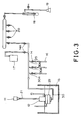
- Fig. 3 is a schematic view showing an apparatus having a construction suitable for performing measurement of pervaporation using the water-organic solvent separation membrane of one embodiment according to the present invention.
- Fig. 4 is an enlarged cross-sectional view showing a pervaporation cell in the apparatus shown in Fig. 3. Referring to Figs. 3 and 4, the method of measuring pervaporation (hereafter, referred to as "PV") will be explained as follows.
- PV pervaporation
- reference numeral 11 denotes a motor for rotating a stirrer 21 provided in a pervaporation cell 12, and a temperature controlled bath 13 in which the pervaporation cell 12 is contained controls temperatures of the feed side and permeate side of the pervaporation cell 12 at constant levels.
- a plurality of cold traps 16 are each connected to a lower chamber 29 through a needle valve 14 provided with each pipe 30A branched from an outlet pipe 30 which is connected to an outlet of the lower chamber 29.
- Each of the cold traps 16 is connected through a frosted glass joint is to the needle valve 14.
- a vacuum gauge 17 and a cold trap 16 are connected to the outlet pipe 30 through the respective needle valves 14A such that the pipes 30A are connected to the outlet pipe 30 between the needle valves 14A and the outlet of the lower chamber 29.
- a cold trap 18 is connected to a vacuum pump 19.
- a plurality of pipes 20 e.g., three pipes as shown in Fig. 3) are connected to the outlet pipe 30 between the cold trap 18 and the needle valve 14A in order to connect other measurement systems to the vacuum pump 19.
- a feed liquid 31 is separated through a thin film 26 sandwiched by a solvent resistant gasket 25 made of fluorine-containing rubber, e.g., Viton gasket, trade name for a product by Tigers Polymer Co., and filter paper 27 as shown in Fig. 4.
- the filter paper 27 is a buffer between a metal plate 28 and the thin film 26 and may be replaced by a thin glass filter.
- the stirrer 21 is passed through a hole pierced through a stopper 22, e.g., Mighty Seal, trade name for a product by Fujiwara Seisakusho Co., Ltd., provided for preventing a solvent from evaporation.
- the feed liquid 31 to be separated is poured into the feed side of the pervaporation cell 12, i.e., an upper chamber 23 of the cell 12 and stirred by the stirrer 21, and is permeated by reducing the pressure in the lower chamber 29 of the cell using the vacuum pump 19.
- the permeate is then collected by the cold traps 16 shown in Fig. 3.
- the weight of the sample (weight of the permeate liquid) is measured.
- the feed liquid 31 after the initiation of measurement for pervaporation and the permeate liquid are analyzed by gas chromatography to determine the compositions of the substance to be permeated and of the substance to be left unpermeated, respectively.
- the measurement of the thickness of the thin film 26 is performed before the initiation of the PV measurement. Separation factor, flux and permeation rate can be obtained by introducing results of these measurements into formulae (1), (2) and (3) above.
- the swelling ratio of the membrane is measured as follows. That is, the membrane sandwiched by two pieces of Tetoron mesh or polyester-based synthetic fiber produced by Toray Industry is immersed in a solution which is adjusted to a predetermined concentration and left to stand in a temperature controlled bath. After standing it for 48 hours, the membrane is taken out from the solution and solution on the surface of the membrane is swept away with filter paper or the like and then the membrane is weighed. The weight thus obtained is defined as a weight at swelling or wet weight, Ww. This membrane is then dried in vacuum for no shorter than 48 hours and the membrane is weighed to obtain a dry weight, Wd.
- the support used is in the form of a flat membrane in the above-described embodiment, particles or hollow fibers may also be used as the support.
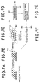
- Figs. 5A to 5D are cross-sectional views each showing a procedure of producing a composite-type separation membrane according to the present invention when particles are used as a substrate for carrying the polymeric film for the separation of an organic solvent from a water-organic solvent mixture.
- a particle layer 41 is composed of the particles having coated on the surfaces thereof with the polymer solution and has a water-organic solvent separation ability so that water-organic solvent separation can be performed reliably without disintegration of the particle layer 41 into individual particles and scattering of the individual particles.
- the particle layer 41 is formed on a surface of a temporary support member 42 made of polyethylene terephthalate, for example.
- a porous membrane 43 is mounted on an exposed surface of the particle layer 41 as shown in Fig. 5C, and then the temporary support member 42 is removed from the particle layer 41.
- Another porous membrane 44 is substituted for the member 42 as shown in Fig. 5D.
- the thus-obtained composite-type separation membrane has a sandwiched structure that the particle layer 41 is sandwiched by the two porous membranes 43 and 44.
- Figs. 6A to 6C are cross-sectional views each showing a procedure of producing a composite-type separation membrane according to the present invention when fibers are used as a support member for supporting the polymeric film for the separation of an organic solvent from a water-organic solvent mixture.
- a plurality of fibers 50 are provided, immersed, for example, in the polymer solution in the vessel 40 shown in Fig. 5A and dried to coat the surfaces of fibers 50 with a polymeric membrane. Then, as shown in Fig. 6B, the surface-coated fibers 50 are arranged on a first porous membrane 51 to form a fiber layer. Next, a second porous membrane 52 is arranged on the fiber layer 50 to obtain a composite-type separation membrane as shown in Fig. 6C.
- the surface-coated fibers 50 having a water-organic solvent separation ability are sandwiched by the two porous membranes 51 and 52, which construction prevents the fibers from scattering so that water-organic solvent separation can be performed reliably.
- Figs. 7A to 7E are explanatory diagrams each showing a procedure of producing a composite-type separation membrane according to the present invention when hollow fibers in the form of a pipe or concentric cylinder are used as a support member for supporting the polymeric film for the separation of an organic solvent from a water-organic solvent mixture.
- a plurality of hollow fibers 60 are provided, immersed, for example, in the polymer solution in the vessel 40 shown in Fig. 5A and dried to coat the outer and inner surfaces of the hollow fibers 60 with a polymeric membrane.
- the coated hollow fibers 60 are arranged on a first flat porous membrane 61 as shown in Fig. 7C.
- a second flat porous membrane 62 is then arranged on the hollow fibers 60 to obtain a composite-type separation membrane as shown in Fig. 7D.
- a module of such a composite-type separation membrane may be made by using an individual composite-type separation membrane as a unit and assembling a plurality of units.
- the coated hollow fibers 60 having a water-organic solvent separation ability on the both outer and inner surfaces thereof are sandwiched by the two porous membranes 61 and 62, and this construction enables practicing the water-organic solvent separation reliably without scattering the hollow fibers 60.
- the hollow fibers 60 have a coated area much larger than the same weight of the fibers 50, the hollow fibers 60 have a water-organic solvent separation ability higher than that of the fibers 50.
- Fig. 7F is an explanatory diagram showing a construction of the composite-type separation membrane in which the hollow fibers 60 are supported by a corrugated porous membrane 63 instead of the flat porous membranes 61 and 62.
- the hollow fibers 60 can be firmly fixed by determining the shape and size of the porous membrane 63 so that the hollow fibers 60 can be put in valley portions of the corrugated porous membrane 63 as shown in Fig. 7F. While Fig. 7F shows that a single follow fiber 60 is provided in each valley portion of the corrugated porous membrane 63, a plurality of the hollow fibers 60 may be arranged in each valley portion thereof.
- toluene-ethyl acetate 1 : 20 by weight
- BA n-butyl acrylate
- AA acrylic acid
- the copolymer had a weight average molecular weight of about 700,000 to 800,000.
- a polytetrafluoroethylene (Teflon, a registered trademark)-based porous membrane a porous membrane of a fluororesin such as Fluoropore (trade name for a product by Sumitomo Electric Industries Co., Ltd.), or a porous cellulose acetate membrane usually employed as an ultrafiltration membrane instead of the porous polypropylene membrane serving as the support member.
- Teflon a polytetrafluoroethylene
- Fluoropore trade name for a product by Sumitomo Electric Industries Co., Ltd.
- a porous cellulose acetate membrane usually employed as an ultrafiltration membrane instead of the porous polypropylene membrane serving as the support member.
- the composite-type separation membrane thus obtained was fitted as a thin film in the apparatus for measuring pervaporation as shown in Figs. 3 and 4, and a mixed solution of water and 1,1,2-trichloroethane (hereafter, referred to as "TCE") at 25°C was fed to the upper chamber of the pervaporation cell and the lower chamber of the cell was evacuated to a reduced pressure of from 0.05 to 0.5 mmHg, and separation of the mixed solution was performed by a pervaporation method to obtain the following results.
- TCE 1,1,2-trichloroethane
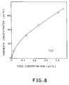
- Fig. 8 is a graph illustrating a relationship between a concentration of TCE in the feed liquid and a concentration of TCE in the permeate liquid.
- the permeate liquid containing about 60 % by weight of TCE was obtained from the feed liquid having a low TCE concentration, e.g., as low as 0.4 % by weight. Because the solubility of TCE in water is 0.45 g/100 g (TCE/water), the resulting permeate liquid separated in two layers.
- permeation rates were 1.08, 1.21, 1.81 and 2.73 ( ⁇ 10 -6 kg ⁇ m/m 2 ⁇ hr), respectively, and separation factors were 629, 373, 379 and 467, respectively.
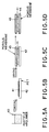
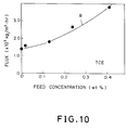
- Figs. 9 and 10 illustrate relationships between a change in a concentration of TCE and a separation factor and total flux, respectively, of the membrane.
- Curve A in Fig. 9 represents a change in a separation factor
- curve B in Fig. 10 represents a change in a total flux.
- the separation factors at low concentrations are about twice as high as the separation factors in other concentration ranges.
- the separation factor obtained by the PV method is expressed in terms of a value which is obtained by dividing the composition ratio of the respective components in the permeate liquid by that of the respective components in the feed liquid, resulting in that a slight change in the concentration of either one substance gives rise to a fluctuation in the separation factor to a greater extent when that substance is contained at a low concentration.
- Permeation rate is calculated by multiplying the flux illustrated by curve B in Fig. 10 with the thickness of the membrane.
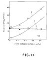
- Fig. 11 illustrates a relationship between a concentration of TCE in the feed liquid and a flux of TCE, that of water, and total flux. These were indicated separately for different components of the permeate liquid in order to illustrate that the total flux and separation factor increase with increase in the concentration of TCE in the feed liquid as illustrated in Figs. 9 and 10.
- curves C, D and E represent changes in the flux of TCE, that of water, and total flux, respectively.
- Curve D demonstrates that the change in the concentration of the feed liquid resulted in substantially no change in the flux of water.
- Curve C demonstrates that the flux of TCE changed several times according as the concentration of the feed liquid changed. It would be because the formula for calculating fluxes contains terms dependent on the concentrations of respective components that the fluxes change as illustrated in curves C and E. Also, the separation factors would be considered to increase according as the proportion of TCE in the permeate liquid increases as a result of the increased flux of TCE against the flux of water being kept constant.
- the permeate liquid separated into two layers, and permeation rates for TCE were each 1.81, 3.90, 8.74 and 18.0 ( ⁇ 10 -7 kg ⁇ m/m 2 ⁇ hr).
- PV measurement was performed on the separation membrane used in Example 1 at temperatures of 40°C, 55°C or 70°C, and the following results were obtained.
- the permeation rate was 3.08 ( ⁇ 10 -6 kg ⁇ m/m 2 ⁇ hr) and separation factor ( ⁇ ) for water was 316.
- the permeation rate was 6.56 ( ⁇ 10 -6 kg ⁇ m/m 2 ⁇ hr) and the separation factor ( ⁇ ) 239; and at 70°C and at 0.15 % by weight, the permeation rate was 1.44 ( ⁇ 10 -5 kg ⁇ m/m 2 ⁇ hr) and the separation factor ( ⁇ ) 145.
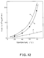
- Fig. 12 illustrates a relationship between a temperature and a flux of TCE, that of water and total flux, respectively.
- curves F, G and H represent changes in the flux of TCE, that of water, and total flux, respectively.
- the flux of TCE changes proportionally to the change in the temperature while the flux of water increases exponentially as the temperature increases as indicated by curve G.
- total flux changes greatly according as the temperature changes as indicated curve H.
- PV measurement was performed using a separation membrane obtained by the same procedures as in Example 1 except that n-butyl acrylate in Example 1 was replaced by lauryl methacrylate (LaMA), and the following results were obtained.
- the thickness and film area of the membrane were the same as in Example 1.
- the permeation rate was 6.66 ( ⁇ 10 -7 kg ⁇ m/m 2 ⁇ hr), and the separation factor ( ⁇ ) of TCE for water was 2,264.
- the permeate liquid was obtained in two separate layers.
- the permeation rate of TCE was 5.24 ( ⁇ 10 -7 kg ⁇ m/m 2 ⁇ hr).
- PV measurement was performed at 25°C using a polystyrene film having a thickness of 42 ⁇ m, and the following results were obtained.
- the permeation rate was 2.05 ( ⁇ 10 -8 kg ⁇ m/m 2 ⁇ hr).
- the TCE in the permeate liquid was below detection limit, and hence it was impossible to calculate the separation factor.
- PV measurement was performed at 25°C using a low density polyethylene film having a thickness of 15 ⁇ m, and the following results were obtained.
- the permeation rate was 5.10 ( ⁇ 10 -8 kg ⁇ m/m 2 ⁇ hr).
- the separation factor of TCE for water was 3,629.
- the permeation rate of TCE in the permeate liquid was 4.50 ( ⁇ 10 -8 kg ⁇ m/m 2 ⁇ hr).
- PV measurement was performed at 25°C using a polyvinyl chloride film having a thickness of 42 ⁇ m, and the following results were obtained.
- the permeation rate was 2.18 ( ⁇ 10 -8 kg ⁇ m/m 2 ⁇ hr).
- the TCE in the permeate liquid was below detection limit, and hence it was impossible to calculate the separation factor like Comparative Example 1.
- Table 1 shows results of measurements obtained in Examples 1 to 3 and Comparative Examples 1 to 3 and Table 2 shows results of measurements obtained in Examples 4 to 8.
- the feed liquid was a water-TCE mixture.
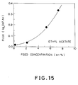
- a water-ethyl acetate mixture was used as the feed liquid.
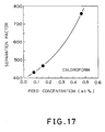
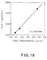
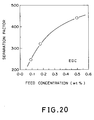
- the feed liquid used were a water-chloroform mixture, a water-EDC mixture, a water-trichlene mixture, and a water-perclene mixture, respectively.
- the concentration of the organic solvent remaining in the feed liquid was within the range of 0.05 to 0.08 % by weight (the initial concentration on the side of the feed liquid: 0.2 % by weight, after continuing the measurement for 3 hours), which reveals that the organic solvent in the water-organic solvent mixtures can be recovered efficiently and water can be purified satisfactorily.
- the permeation rate of the mixed solution was 0.0998, 0.245, 1.25, or 2.34 ( ⁇ 10 -5 kg ⁇ m/m 2 ⁇ hr), respectively; and the separation factor ( ⁇ ) of ethyl acetate for water was 29.1, 59.3, 123, or 96.3, respectively.
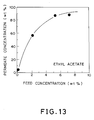
- the permeate liquid was obtained in two separate layers, and the permeation rate of ethyl acetate was 0.00445, 0.138, 1.09 or 2.07 ( ⁇ 10 -5 kg ⁇ m/m 2 ⁇ hr). Based on these results, Fig.
- Fig. 13 illustrates the effect of feed concentration on the permeate concentration
- Fig. 14 illustrates the effect of feed concentration on the separation factor of ethyl acetate-water mixture
- Fig. 15 illustrates the effect of feed concentration on the flux of ethyl acetate-water mixture.
- Fig. 16 illustrates the effect of feed concentration on the permeate concentration
- Figs. 17 and 18 illustrate the effects of feed concentration on the separation factor and flux, respectively.
- Fig. 19 illustrates the effect of feed concentration on the permeate concentration
- Figs. 20 and 21 illustrate the effect of feed concentration on the separation factor and flux, respectively.
- Fig. 22 illustrates the effect of feed concentration on the permeate concentration
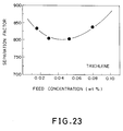
- Figs. 23 and 24 illustrate the effects of feed concentration on the separation factor and flux, respectively.
- Fig. 25 illustrates the effect of feed concentration on the permeate concentration
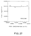
- Figs. 26 and 27 illustrate the effects of feed concentration on the separation factor and flux , respectively.
- Copolymers with acrylic acid were prepared by repeating the same procedures as in Example 1 except that n-butyl acrylate (BA) used in Example 1 was replaced by t-butyl acrylate (tert-BA), cyclohexyl acrylate (CHA) or benzyl acrylate (BeA), and separation membranes were made using the copolymers thus obtained.
- Various measurements were made in order to compare the thin films made of the copolymers with the thin films BA-AA and LaMA-AA in Examples 1 and 3, respectively. Results obtained are shown in Table 3.
- BA-AA and LaMA-AA membranes were ascribable to their glass transition temperatures (Tg) being lower than the rest three.
- Tg glass transition temperatures
- BA-AA membrane had a Tg of 227.4K
- LaMA-AA had a Tg of 216.5K.
- the rest three types of membranes had each a Tg no lower than about room temperature.
- the permeation rate was 1.97 ( ⁇ 10 -6 kg ⁇ m/m 2 ⁇ hr), and the separation factor of TCE for water was 731. Further, the permeation rate of TCE in the permeate liquid was 1.17 ( ⁇ 10 -6 kg ⁇ m/m 2 ⁇ hr).
- BA n-butyl acrylate
- MA methyl acrylate
- HOA 2-hydroxyethyl acrylate
- TPTDI trimethylolpropane adduct toluylenediisocyanate
- the permeation rate was 2.47 ( ⁇ 10 -6 kg ⁇ m/m 2 ⁇ hr), and the separation factor of TCE for water was 473. Further, the permeation rate of TCE in the permeate liquid was 1.22 ( ⁇ 10 -6 kg ⁇ m/m 2 ⁇ hr).
- the permeation rate was 2.56 ( ⁇ 10 -6 kg ⁇ m/m 2 ⁇ hr), and the separation factor of TCE for water was 639. Further, the permeation rate of TCE in the permeate liquid was 1.43 ( ⁇ 10 -6 kg ⁇ m/m 2 ⁇ hr).
- BA n-butyl acrylate
- MMA methyl methacrylate
- HOA 2-hydroxyethyl acrylate
- TMPI trimethylolpropane adduct toluylenediisocyanate
- the permeation rate was 2.32 ( ⁇ 10 -6 kg ⁇ m/m 2 ⁇ hr), and the separation factor of TCE for water was 667. Further, the permeation rate of TCE in the permeate liquid was 1.32 ( ⁇ 10 -6 kg ⁇ m/m 2 ⁇ hr).
- Table 4 shows experimental results on the separation membranes obtained in Examples 10 to 13.
- Example 10 BA-AA (97:3) 0.199 731 1.97 1.44
- Example 11 BA-MA-HEA (60:30:10) 0.207 473 2.47 1.17
- Example 12 BA-MA-HEA (83:10:7) 0.199 639 2.56 1.64
- the separation membranes of the present invention have the following effects.
Landscapes
- Chemical & Material Sciences (AREA)
- Chemical Kinetics & Catalysis (AREA)
- Engineering & Computer Science (AREA)
- Water Supply & Treatment (AREA)
- Separation Using Semi-Permeable Membranes (AREA)
Description
| Concentration of Organic Solvents in feed (wt%) | Temperature (°C) | Permeation Rate (kg·m/m2·hr) | Separation Factor (α) | Permeation Rate × α (kg·m/m2·hr) | |
| Example 1 | 0.018 | 25 | 1.08 × 10⁻⁶ | 629 | 6.79 × 10⁻⁴ |
| 0.13 | 25 | 1.21 × 10⁻⁶ | 373 | 4.51 × 10⁻⁴ | |
| 0.24 | 25 | 1.81 × 10⁻⁶ | 379 | 6.86 × 10⁻⁴ | |
| 0.41 | 25 | 2.73 × 10⁻⁶ | 467 | 1.27 × 10⁻³ | |
| Example 2 | 0.17 | 40 | 3.08 × 10⁻⁶ | 316 | 9.73 × 10⁻⁴ |
| 0.14 | 55 | 6.56 × 10⁻⁶ | 239 | 1.57 × 10⁻³ | |
| 0.15 | 70 | 1.44 × 10⁻⁶ | 145 | 2.09 × 10⁻⁴ | |
| Example 3 | 0.19 | 25 | 6.66 × 10⁻⁷ | 2264 | 1.51 × 10⁻³ |
| Comparative 1 | 0.21 | 25 | 2.05 × 10⁻⁸ | - | - |
| Comparative 2 | 0.18 | 25 | 5.10 × 10⁻⁸ | 3629 | 1.85 × 10⁻⁴ |
| Comparative 3 | 0.20 | 25 | 2.18 × 10⁻⁸ | - | - |
| Concentration of Organic Solvents in feed (wt%) | Temperature (°C) | Permeation Rate (kg·m/m2·hr) | Separation Factor (α) | Permeation Rate × α (kg·m/m2·hr) | |
| Example 4 | 0.162 | 25 | 0.0998 × 10⁻⁵ | 29.1 | 2.90 × 10⁻⁵ |
| 2.14 | 25 | 0.245 × 10⁻⁵ | 59.3 | 1.45 × 10⁻⁴ | |
| 5.33 | 25 | 1.25 × 10⁻⁵ | 123 | 1.54 × 10⁻³ | |
| 7.33 | 25 | 2.34 × 10⁻⁵ | 96.3 | 2.25 × 10⁻³ | |
| Example 5 | 0.0807 | 25 | 0.811 × 10⁻⁶ | 433 | 3.51 × 10⁻⁴ |
| 0.155 | 25 | 1.07 × 10⁻⁶ | 467 | 5.00 × 10⁻⁴ | |
| 0.470 | 25 | 2.32 × 10⁻⁶ | 758 | 1.76 × 10⁻³ | |
| Example 6 | 0.0922 | 25 | 1.32 × 10⁻⁶ | 246 | 3.25 × 10⁻⁴ |
| 0.175 | 25 | 1.70 × 10⁻⁶ | 320 | 5.44 × 10⁻⁴ | |
| 0.500 | 25 | 3.43 × 10⁻⁶ | 441 | 1.51 × 10⁻³ | |
| Example 7 | 0.0160 | 25 | 1.15 × 10⁻⁶ | 833 | 9.58 × 10⁻⁴ |
| 0.0297 | 25 | 1.25 × 10⁻⁶ | 804 | 1.01 × 10⁻³ | |
| 0.0529 | 25 | 1.46 × 10⁻⁶ | 804 | 1.17 × 10⁻³ | |
| 0.0798 | 25 | 1.53 × 10⁻⁶ | 838 | 1.28 × 10⁻³ | |
| Example 8 | 11.2 (ppm) | 25 | 10.0 × 10⁻⁷ | 2682 | 2.68 × 10⁻³ |
| 35.3 (ppm) | 25 | 9.03 × 10⁻⁷ | 1177 | 1.06 × 10⁻³ | |
| 65.2 (ppm) | 25 | 9.75 × 10⁻⁷ | 905 | 8.82 × 10⁻⁴ | |
| 92.4 (ppm) | 25 | 9.95 × 10⁻⁷ | 977 | 9.72 × 10⁻⁴ |
| Thin Film | Feed Concentration TCE (wt%) | α (TCE/water) | Permeation Rate (× 10-7kg·m/m2·hr) | Swelling Ratio | Thickness (µm) |
| BA-AA | 0.170 | 485 | 15.7 | 14.44 | 65.6 |
| LaMA-AA | 0.193 | 2264 | 6.52 | 10.25 | 47.6 |
| tert-BA-AA | 0.182 | 8.20 | 3.76 | 6.485 | 74.0 |
| CHA-AA | 0.186 | 31.0 | 2.17 | 8.198 | 59.6 |
| BeA-AA | 0.201 | 108 | 5.05 | 8.681 | 79.2 |
| Thin Film | Feed Concentration TCE (wt%) | α (TCE/water) | R (× 10-6kg·m/m2·hr) | R × α (× 10-3kg·m/m2·hr) | |
| Example 10 | BA-AA (97:3) | 0.199 | 731 | 1.97 | 1.44 |
| Example 11 | BA-MA-HEA (60:30:10) | 0.207 | 473 | 2.47 | 1.17 |
| Example 12 | BA-MA-HEA (83:10:7) | 0.199 | 639 | 2.56 | 1.64 |
| Example 13 | BA-MMA-HEA (78:15:7) | 0.196 | 667 | 2.32 | 1.55 |
Claims (18)
- A membrane for separating an organic solvent from a water-organic solvent mixture, comprising a copolymer consisting essentially of an α,β-unsaturated carbonyl compound as a main monomer, wherein said α,β-unsaturated carbonyl compound being an acrylic acid ester or a methacrylic acid ester of a hydrocarbon-based group which has a high affinity for a specific organic solvent and a second α,β-unsaturated carbonyl compound which has a reactive functional group that can be crosslinked with a crosslinking agent as another monomer
- A membrane as claimed in claim 1, characterized in that said reactive functional group of said copolymer is selected from the group consisting of a carboxyl group, a hydroxyl group, a glycidyl group and an amino group.
- A membrane as claimed in claim 1, characterized in that said crosslinking agent is selected from the group consisting of a polyisocyanate, a melamine resin, an epoxy resin, a metal chelate, a polyvalent metal and a polyamine.
- A membrane as claimed in claim 1, further characterized by comprising a support member for supporting said polymeric membrane.
- A membrane as claimed in claim 4, characterized in that said support member is in the form of a flat membrane.
- A membrane as claimed in claim 4, characterized in that said polymeric membrane is arranged on the surface of at least one pipe as said support member.
- A membrane as claimed in claim 6, characterized in that said pipe is a concentric cylinder.
- A membrane as claimed in claim 4, characterized in that said polymeric membrane is coated on the surface of hollow fibers as said support member.
- A membrane as claimed in claim 4, characterized in that said support member is supported on a porous membrane.
- A membrane as claimed in claim 1, characterized in that said polymeric membrane includes particles therein.
- A membrane as claimed in claim 10, characterized in that said polymeric membrane is supported on a porous member.
- A composite-type separation membrane comprisinga polymeric membrane according to claim 1; andat least one support member which is arranged on said polymeric membrane.
- A membrane as claimed in claim 1, wherein said polymeric membrane is effective for separating an organic solvent from a water-organic solvent mixture wherein the organic solvent is present in a low concentration.
- A membrane as claimed in claim 1, wherein said hydrocarbon-based group is selected from the group consisting of an n-butyl group, a tert-butyl group, a benzyl group, and a dodecyl group.
- A membrane as claimed in claim 1, wherein said polymer is crosslinked by a crosslinking agent comprising tetraglycidyl metaxylenediamine.
- A process for separating an organic solvent from a liquid mixture containing the organic solvent, which process comprises:providing a membrane according to claim 1;feeding a liquid mixture containing an organic solvent to be separated on one side of said membrane;evacuating the other side of said membrane by aspiration to have a component permeated through said membrane; andcollecting the permeated component.
- A process as claimed in claim 16, wherein said liquid mixture containing an organic solvent to be separated is selected from the group consisting of an azeotropic mixture, an isomeric mixture, industrial waste water, underground water and a solution with an organic solvent having a boiling point higher than water.
- The use of a membrane according to claim 1 for selective permeation of organic solvents from water-organic solvent mixtures.
Applications Claiming Priority (5)
| Application Number | Priority Date | Filing Date | Title |
|---|---|---|---|
| JP15400490 | 1990-06-14 | ||
| JP154004/90 | 1990-06-14 | ||
| JP131400/91 | 1991-06-03 | ||
| JP13140091A JP3195377B2 (en) | 1990-06-14 | 1991-06-03 | Organic solvent selective permeable membrane |
| AU79300/91A AU635430B1 (en) | 1990-06-14 | 1991-06-25 | Membrane for separating an organic solvent from a water-organic solvent mixture |
Publications (3)
| Publication Number | Publication Date |
|---|---|
| EP0461607A2 EP0461607A2 (en) | 1991-12-18 |
| EP0461607A3 EP0461607A3 (en) | 1993-02-24 |
| EP0461607B1 true EP0461607B1 (en) | 1998-04-08 |
Family
ID=27156335
Family Applications (1)
| Application Number | Title | Priority Date | Filing Date |
|---|---|---|---|
| EP91109543A Expired - Lifetime EP0461607B1 (en) | 1990-06-14 | 1991-06-11 | Membrane for separating an organic solvent from a water-organic solvent mixture |
Country Status (4)
| Country | Link |
|---|---|
| US (1) | US5173189A (en) |
| EP (1) | EP0461607B1 (en) |
| JP (1) | JP3195377B2 (en) |
| AU (1) | AU635430B1 (en) |
Families Citing this family (23)
| Publication number | Priority date | Publication date | Assignee | Title |
|---|---|---|---|---|
| JPH0712420B2 (en) * | 1991-12-27 | 1995-02-15 | 工業技術院長 | Separation membrane for dehydration |
| GB9423805D0 (en) * | 1994-11-25 | 1995-01-11 | Bratton Graham J | Dehydration apparatus |
| TW311947B (en) * | 1995-06-05 | 1997-08-01 | Kuraray Co | |
| NL1001060C2 (en) * | 1995-08-25 | 1997-02-27 | Tno | Membrane and method for separating aromatic hydrocarbons from a mixture of various aromatic hydrocarbons or from a mixture of such aromatic hydrocarbons and non-aromatic hydrocarbons. |
| US6316684B1 (en) | 1999-09-01 | 2001-11-13 | Membrane Technology And Research, Inc. | Filled superglassy membrane |
| BRPI0608363A2 (en) | 2005-03-09 | 2011-05-31 | Univ California | nanocomposite membranes and methods of fabrication and use thereof |
| US8017016B2 (en) * | 2006-07-07 | 2011-09-13 | Sims Carl W | Method and apparatus for pervaporation control in chromatographic systems |
| CA2667579A1 (en) * | 2006-10-27 | 2008-05-15 | The Regents Of The University Of California | Micro-and nanocomposite support structures for reverse osmosis thin film membranes |
| WO2009039467A1 (en) * | 2007-09-21 | 2009-03-26 | The Regents Of The University Of California | Nanocomposite membranes and methods of making and using same |
| US8177978B2 (en) | 2008-04-15 | 2012-05-15 | Nanoh20, Inc. | Reverse osmosis membranes |
| EP2448657B1 (en) | 2009-06-29 | 2018-12-26 | NanoH2O Inc. | Improved hybrid tfc ro membranes with nitrogen additives |
| JP5897458B2 (en) * | 2010-03-26 | 2016-03-30 | 日本碍子株式会社 | Pervaporation separation method |
| JP5851508B2 (en) * | 2010-09-20 | 2016-02-03 | スルザー ケムテック アクチェンゲゼルシャフト | Membrane having non-porous separation layer, and use and manufacturing method of membrane |
| WO2012064939A2 (en) | 2010-11-10 | 2012-05-18 | Nanoh2O, Inc. | Improved hybrid tfc ro membranes with non-metallic additives |
| US8440003B2 (en) | 2011-03-25 | 2013-05-14 | Idex Health & Science, Llc | Apparatus for pervaporation control in liquid degassing systems |
| US8430949B2 (en) | 2011-03-25 | 2013-04-30 | Idex Health & Science Llc | Apparatus for pervaporation control in liquid degassing systems |
| US8668763B2 (en) | 2011-03-25 | 2014-03-11 | Idex Health & Science Llc | Apparatus for pervaporation control in liquid degassing systems |
| US9555376B2 (en) | 2013-01-26 | 2017-01-31 | Adma Products, Inc. | Multilayer, micro- and nanoporous membranes with controlled pore sizes for water separation and method of manufacturing thereof |
| US9861940B2 (en) | 2015-08-31 | 2018-01-09 | Lg Baboh2O, Inc. | Additives for salt rejection enhancement of a membrane |
| US9737859B2 (en) | 2016-01-11 | 2017-08-22 | Lg Nanoh2O, Inc. | Process for improved water flux through a TFC membrane |
| US10155203B2 (en) | 2016-03-03 | 2018-12-18 | Lg Nanoh2O, Inc. | Methods of enhancing water flux of a TFC membrane using oxidizing and reducing agents |
| CN106964262B (en) * | 2017-04-13 | 2020-08-11 | 东华大学 | A kind of nanofiber-based pervaporation composite membrane and preparation method thereof |
| CN112574469B (en) * | 2019-09-27 | 2022-07-12 | 中国石油化工股份有限公司 | Water removal method for synthetic rubber solvent |
Family Cites Families (10)
| Publication number | Priority date | Publication date | Assignee | Title |
|---|---|---|---|---|
| US3227510A (en) * | 1958-03-04 | 1966-01-04 | Tee Pak Inc | Dyeing substrates ionically binding in localized areas catalysts for the predyeing olefin polymerization thereon |
| US4085168A (en) * | 1971-02-22 | 1978-04-18 | Cpc International Inc. | Chemically joined, phase separated self-cured hydrophilic thermoplastic graft copolymers and their preparation |
| US4267295A (en) * | 1979-02-09 | 1981-05-12 | Syntex (U.S.A.) Inc. | Polymeric compositions and hydrogels formed therefrom |
| US4415455A (en) * | 1982-11-09 | 1983-11-15 | Rohm And Haas Company | Reverse osmosis membranes based on hydroxyalkyl methacrylate and methacrylic acid copolymers |
| NZ208867A (en) * | 1983-07-14 | 1986-07-11 | Holland Hitch Au Ltd | Adjustable height fifth wheel coupling |
| GB8419174D0 (en) * | 1984-07-27 | 1984-08-30 | British Petroleum Co Plc | Separation of water from organic liquids |
| US4725359A (en) * | 1985-02-25 | 1988-02-16 | Bend Research, Inc. | Potable water from internal combustion engines |
| GB2174619B (en) * | 1985-05-07 | 1989-05-04 | Us Energy | Pervaporation separation of ethanol-water mixtures using polyacrylic acid composite membranes |
| DE3814326A1 (en) * | 1988-04-28 | 1989-11-09 | Akzo Gmbh | METHOD FOR MODIFYING CELLULOSIC DIALYSIS MEMBRANES FOR IMPROVING BIOCOMPATIBILITY AND DEVICE FOR IMPLEMENTING THE METHOD |
| DE3911697A1 (en) * | 1989-04-10 | 1990-10-25 | Gessner & Co Gmbh | USE OF A MICROPOROUS MEMBRANE CONSTRUCTED FROM A POLYMERIC SUBSTRATE AND A SURFACE COATING OF THE SUBSTRATE WITH A POLYACRYLIC ACID OR METHACRYLIC ACID DERIVATIVE FOR THE FILTRATION OF BEER |
-
1991
- 1991-06-03 JP JP13140091A patent/JP3195377B2/en not_active Expired - Fee Related
- 1991-06-11 EP EP91109543A patent/EP0461607B1/en not_active Expired - Lifetime
- 1991-06-12 US US07/714,036 patent/US5173189A/en not_active Expired - Fee Related
- 1991-06-25 AU AU79300/91A patent/AU635430B1/en not_active Ceased
Also Published As
| Publication number | Publication date |
|---|---|
| AU635430B1 (en) | 1993-03-18 |
| JPH04227037A (en) | 1992-08-17 |
| EP0461607A3 (en) | 1993-02-24 |
| JP3195377B2 (en) | 2001-08-06 |
| EP0461607A2 (en) | 1991-12-18 |
| US5173189A (en) | 1992-12-22 |
Similar Documents
| Publication | Publication Date | Title |
|---|---|---|
| US5173189A (en) | Membrane for separating an organic solvent from a water-organic solvent mixture | |
| Aminabhavi et al. | Pervaporation separation of organic-aqueous and organic-organic binary mixtures | |
| Lee et al. | Sorption, diffusion, and pervaporation of organics in polymer membranes | |
| US4602922A (en) | Method of making membranes for gas separation and the composite membranes | |
| Zhang et al. | Pervaporation membranes | |
| CA2290593C (en) | Non-porous gas permeable membrane | |
| US6884375B2 (en) | Hydrophobic membrane materials for filter venting applications | |
| US20100147763A1 (en) | Modified porous membranes, methods of membrane pore modification, and methods of use thereof | |
| JP2011527632A (en) | Water purification membrane with improved contamination resistance | |
| US4976897A (en) | Composite porous membranes and methods of making the same | |
| GB2233252A (en) | Hydrophobic membranes | |
| Liu et al. | Nanofiltration membranes prepared by direct microemulsion copolymerization using poly (ethylene oxide) macromonomer as a polymerizable surfactant | |
| CA2572412C (en) | Membrane gas separation | |
| Schwarz et al. | Membranes based on polyelectrolyte–surfactant complexes for methanol separation | |
| Ohshima et al. | Pervaporation characteristics of cross-linked poly (dimethylsiloxane) membranes for removal of various volatile organic compounds from water | |
| US4659590A (en) | Pervaporation separation of ethanol-water mixtures using polyethylenimine composite membranes | |
| JPS588517A (en) | Method for producing gas selectively permeable composite membrane | |
| US20120132590A1 (en) | Method for fabrication of elastomeric asymmetric membranes from hydrophobic polymers | |
| US5700374A (en) | Pervaporation membranes and use thereof | |
| JPS6154204A (en) | Composite fluid separation membrane | |
| US7485233B2 (en) | Hydrophilic mixed matrix material having reversible water absorbing properties | |
| JPS61281138A (en) | Composite membrane selectively transmitting water from ethanol/water mixture and its production | |
| JPH06218254A (en) | Composite film and performance-recovering method therefor | |
| JPS62250907A (en) | Separation membrane performance recovery method | |
| DE69129209T2 (en) | Membrane for separating an organic solvent from a mixture of water and organic solvent |
Legal Events
| Date | Code | Title | Description |
|---|---|---|---|
| PUAI | Public reference made under article 153(3) epc to a published international application that has entered the european phase |
Free format text: ORIGINAL CODE: 0009012 |
|
| 17P | Request for examination filed |
Effective date: 19910710 |
|
| AK | Designated contracting states |
Kind code of ref document: A2 Designated state(s): DE FR GB IT NL SE |
|
| RAP1 | Party data changed (applicant data changed or rights of an application transferred) |
Owner name: LINTEC CORPORATION |
|
| PUAL | Search report despatched |
Free format text: ORIGINAL CODE: 0009013 |
|
| AK | Designated contracting states |
Kind code of ref document: A3 Designated state(s): DE FR GB IT NL SE |
|
| 17Q | First examination report despatched |
Effective date: 19940310 |
|
| GRAG | Despatch of communication of intention to grant |
Free format text: ORIGINAL CODE: EPIDOS AGRA |
|
| GRAG | Despatch of communication of intention to grant |
Free format text: ORIGINAL CODE: EPIDOS AGRA |
|
| GRAH | Despatch of communication of intention to grant a patent |
Free format text: ORIGINAL CODE: EPIDOS IGRA |
|
| GRAH | Despatch of communication of intention to grant a patent |
Free format text: ORIGINAL CODE: EPIDOS IGRA |
|
| GRAA | (expected) grant |
Free format text: ORIGINAL CODE: 0009210 |
|
| AK | Designated contracting states |
Kind code of ref document: B1 Designated state(s): DE FR GB IT NL SE |
|
| PG25 | Lapsed in a contracting state [announced via postgrant information from national office to epo] |
Ref country code: IT Free format text: LAPSE BECAUSE OF FAILURE TO SUBMIT A TRANSLATION OF THE DESCRIPTION OR TO PAY THE FEE WITHIN THE PRE;WARNING: LAPSES OF ITALIAN PATENTS WITH EFFECTIVE DATE BEFORE 2007 MAY HAVE OCCURRED AT ANY TIME BEFORE 2007. THE CORRECT EFFECTIVE DATE MAY BE DIFFERENT FROM THE ONE RECORDED.SCRIBED TIME-LIMIT Effective date: 19980408 Ref country code: NL Free format text: LAPSE BECAUSE OF FAILURE TO SUBMIT A TRANSLATION OF THE DESCRIPTION OR TO PAY THE FEE WITHIN THE PRESCRIBED TIME-LIMIT Effective date: 19980408 |
|
| REF | Corresponds to: |
Ref document number: 69129209 Country of ref document: DE Date of ref document: 19980514 |
|
| PGFP | Annual fee paid to national office [announced via postgrant information from national office to epo] |
Ref country code: GB Payment date: 19980527 Year of fee payment: 8 |
|
| ET | Fr: translation filed | ||
| PGFP | Annual fee paid to national office [announced via postgrant information from national office to epo] |
Ref country code: FR Payment date: 19980617 Year of fee payment: 8 |
|
| PG25 | Lapsed in a contracting state [announced via postgrant information from national office to epo] |
Ref country code: SE Free format text: LAPSE BECAUSE OF FAILURE TO SUBMIT A TRANSLATION OF THE DESCRIPTION OR TO PAY THE FEE WITHIN THE PRESCRIBED TIME-LIMIT Effective date: 19980708 |
|
| PGFP | Annual fee paid to national office [announced via postgrant information from national office to epo] |
Ref country code: DE Payment date: 19980828 Year of fee payment: 8 |
|
| NLV1 | Nl: lapsed or annulled due to failure to fulfill the requirements of art. 29p and 29m of the patents act | ||
| PLBE | No opposition filed within time limit |
Free format text: ORIGINAL CODE: 0009261 |
|
| STAA | Information on the status of an ep patent application or granted ep patent |
Free format text: STATUS: NO OPPOSITION FILED WITHIN TIME LIMIT |
|
| 26N | No opposition filed | ||
| PG25 | Lapsed in a contracting state [announced via postgrant information from national office to epo] |
Ref country code: GB Free format text: LAPSE BECAUSE OF NON-PAYMENT OF DUE FEES Effective date: 19990611 |
|
| PG25 | Lapsed in a contracting state [announced via postgrant information from national office to epo] |
Ref country code: FR Free format text: THE PATENT HAS BEEN ANNULLED BY A DECISION OF A NATIONAL AUTHORITY Effective date: 19990630 |
|
| GBPC | Gb: european patent ceased through non-payment of renewal fee |
Effective date: 19990611 |
|
| PG25 | Lapsed in a contracting state [announced via postgrant information from national office to epo] |
Ref country code: DE Free format text: LAPSE BECAUSE OF NON-PAYMENT OF DUE FEES Effective date: 20000503 |
|
| REG | Reference to a national code |
Ref country code: FR Ref legal event code: ST |