EP0460713A2 - Appareil de visualisation stéréoscopique - Google Patents
Appareil de visualisation stéréoscopique Download PDFInfo
- Publication number
- EP0460713A2 EP0460713A2 EP19910113408 EP91113408A EP0460713A2 EP 0460713 A2 EP0460713 A2 EP 0460713A2 EP 19910113408 EP19910113408 EP 19910113408 EP 91113408 A EP91113408 A EP 91113408A EP 0460713 A2 EP0460713 A2 EP 0460713A2
- Authority
- EP
- European Patent Office
- Prior art keywords
- card
- plate
- housing
- viewer
- images
- Prior art date
- Legal status (The legal status is an assumption and is not a legal conclusion. Google has not performed a legal analysis and makes no representation as to the accuracy of the status listed.)
- Withdrawn
Links
Images
Classifications
-
- A—HUMAN NECESSITIES
- A63—SPORTS; GAMES; AMUSEMENTS
- A63J—DEVICES FOR THEATRES, CIRCUSES, OR THE LIKE; CONJURING APPLIANCES OR THE LIKE
- A63J15/00—Peep-shows, e.g. raree-shows; Kaleidoscopic or other opalescence exhibitions
-
- G—PHYSICS
- G02—OPTICS
- G02B—OPTICAL ELEMENTS, SYSTEMS OR APPARATUS
- G02B30/00—Optical systems or apparatus for producing three-dimensional [3D] effects, e.g. stereoscopic images
- G02B30/20—Optical systems or apparatus for producing three-dimensional [3D] effects, e.g. stereoscopic images by providing first and second parallax images to an observer's left and right eyes
- G02B30/34—Stereoscopes providing a stereoscopic pair of separated images corresponding to parallactically displaced views of the same object, e.g. 3D slide viewers
-
- G—PHYSICS
- G03—PHOTOGRAPHY; CINEMATOGRAPHY; ANALOGOUS TECHNIQUES USING WAVES OTHER THAN OPTICAL WAVES; ELECTROGRAPHY; HOLOGRAPHY
- G03B—APPARATUS OR ARRANGEMENTS FOR TAKING PHOTOGRAPHS OR FOR PROJECTING OR VIEWING THEM; APPARATUS OR ARRANGEMENTS EMPLOYING ANALOGOUS TECHNIQUES USING WAVES OTHER THAN OPTICAL WAVES; ACCESSORIES THEREFOR
- G03B23/00—Devices for changing pictures in viewing apparatus or projectors
- G03B23/08—Devices for changing pictures in viewing apparatus or projectors in which pictures are attached to a movable carrier
- G03B23/10—Devices for changing pictures in viewing apparatus or projectors in which pictures are attached to a movable carrier drum or disc carrier
- G03B23/105—Devices for changing pictures in viewing apparatus or projectors in which pictures are attached to a movable carrier drum or disc carrier disc carriers
Definitions
- the present invention concerns an improvement in stereoscopic viewers. More particularly, the invention concerns a stereoscopic viewer for displaying pairs of stereo film images, which are peripherally arranged around a disc-shaped carrying card.
- Hand-held stereoscopic viewers have previously been developed for viewing stereo pairs of images arranged on viewing cards. Examples of such viewers include the following U.S. design patents: Des. 171,049; Des. 174,902; Des. 175,215; Des. 184,356; Des. 185,670; and Des. 189,006. Other patents, which describe the mechanical action of such viewers, include U.S. 2,189,285 and 2,511,334.
- a hand-held viewer comprising a housing with a pair of spaced eyepieces through the front of the housing.
- the eyepieces each carry magnifying lenses through which the stereo images are viewed at the focal plane of the lenses.
- the rear of the housing contains a translucent area behind the film images aligned with the viewing axes of the lenses for introducing light into the housing and illuminating the stereo images.
- the translucent area is usually made of a milky plastic that obscures the internal parts of the housing.
- An advancing mechanism is provided in many of the housings for incrementally moving the card to display sequential images through the lenses. These advancing mechanisms typically comprise an integral advancing plate and a sidewardly extending finger actuated trigger lever. Actuation of the trigger moves the advancing plate within the housing to bring a pawl on the plate into engagement with a slot in the card to incrementally advance the displayed images.
- the small, translucent windows which permit light to enter the housing are usually spaced a substantial distance from the viewing card such that movement of the card cannot be detected through the windows.
- the windows also occupy a limited area of the housing, thereby admitting a small amount of light into the interior of the housing for illumination of the film images.
- the side-extending trigger of existing viewers can be awkward to operate since it is difficult to grasp the viewer and reciprocate the trigger with the same hand.
- the sidewardly extending trigger of the prior art must be moved along a vertical slot through the side of the housing from the top to the bottom of the viewer to move the actuator plate. Such a movement requires that the housing be firmly grasped by both hands since manipulation of the sidewardly extending trigger interferes with the trigger hand's hold on the housing.
- the advancing plate which incrementally advances the card for viewing sequential images usually contains a flexible arm having a terminal pawl that engages a slot on the card to advance the card as the trigger moves the plate.
- the pawl will only work effectively if the card is firmly retained against the plate so that the pawl will be retained in the slot during advancement.
- the card was held against the plate by ridges or projections inside the housing which abutted the card when the card was in place on the plate.
- the invention provides a stereoscopic viewer for a plurality of discrete film images equally spaced peripherally around the edge of a disc-shaped carrying card, said film images being arranged in pairs of images which provide a stereoscopic effect when said pairs are viewed together, said card having a plurality of peripherally spaced openings through which images are viewed, and a plurality of equally spaced radial slots, said viewer comprising a housing having retaining means for retaining said card in a viewing plane for rotation of said card about its axis, said viewer being characterised by said housing including a light transmitting face which is parallel to and spaced from said viewing plane and which is translucent substantially across its entire area.
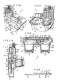
- a stereoscopic viewer 10 constructed in accordance with the invention is adapted sequentially to display a plurality of discrete transparent film images 12 equally spaced peripherally around the edge of a circular carrying card 14 such as illustrated in Figs. 10 and 11.
- Film images 12 are arranged in stereo pairs so as to provide a stereoscopic effect when the pairs are viewed together through a pair of eyepieces 16L, 16R in the viewer 10 each having a magnifying lens 18L, 18R with a common focal plane.
- the lenses 18L, 18R are held within their respective eyepieces by retainers 19L, 19R (Figs. 3 and 4) within the eyepieces 16L, 16R.
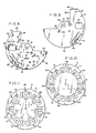
- the mounting card of the present invention comprises an upper lamination 20 (Fig. 11) and a lower lamination 22 (Fig. 10), each lamination preferably being formed of smoothly finished, printable, thin fiberboard, the two being adhered to each other substantially throughout their contiguous surfaces to form a substantially rigid, yet somewhat flexible mounting card 14.
- the card is shaped like a disc so that the card can freely rotate within the viewer 10, the arcuate edges of the card also facilitating insertion into the viewer.
- the card 14 has a hole 15 at its center, and a plurality of substantially rectangular windows 24 equally spaced peripherally adjacent the edge of card 14.
- a plurality of left transparent images 12A L through 12G L are mounted in the windows 24 and a plurality of right transparent images 12A R through 12G R are mounted in the windows 24.
- each of the left images is mounted diametrically opposite the corresponding right images, images 12A L being opposte 12A R , 12B L opposite 12B R , etc.
- the transparencies are suitably secured between the laminations 20, 22.
- the centers of the right and left transparencies are spaced apart the average human interpupillary distance so that the pair of eyepiece lenses 18 in alignment therewith may be placed adjacent the eyes and the view seen in three dimension on an enlarged scale.
- Images 12 are alternately oriented in windows 24 such that each immediately succeeding image is upside down as compared to the immediately preceding image on the card. For example, image 12A L is upright and image 12E R is upside down.
- This arrangement of images allows card 14 to be advanced by two windows (from 12A L to 12B L ) each time a trigger is depressed. Further details concerning the structure of the disc and reasons for orienting the images in this fashion are more fully explained in U.S Patent No. 2,189,285, which is incorporated by reference herein.
- the card has seven equally spaced radial slots 26a through 26g therearound, one slot being positioned between each of the following pairs of windows 12: A L and E R , B L and F R , C L and G R , D L and A R , E L and B R , F L and C R , and G L and D R .
- the slots are of equal length and are located between the peripheral edge of the card 14 and the windows 24.
- Seven separate groups of printed indicia A-G are provided on the face of upper lamination 20 comprising legends which correspond one to each of the pairs views shown by stereo images. Each legend is offset by an angle of about 90° from the pair of images to which it corresponds.
- the viewer 10 comprises a hollow housing 32 (Figs. 1 and 2), comprising a front element 34 and rear element 36 (Figs. 1-4), the two elements meeting along a vertical parting plane.
- the elements 34, 36 are adapted to be molded of a suitable plastic such as high impact styrene.
- the front element 34 is molded from a pigmented plastic providing a desired color and rendering the element light opaque.
- Rear element 36 is molded of a plastic such that the element will be translucent.
- the front element 34 is provided with a plurality of fastener receiving sockets 38 (Figs. 4. 6 and 7) extending perpendicularly to the parting plane and into which the opposed ends of prong fasteners 40 (Fig.
- the sockets 38 and fasteners 40 are arranged around the bottom and sides of the housing 32 but are positioned such that a top slot 41 (Figs. 2 and 3) is unobstructed for insertion of the card 14 therethrough.
- the rear element 36 comprises a dish shaped substantially circular lower portion 46 from which extends a peripheral flange 48 (Figs. 1 and 3).
- the top of the portion 46 is cut away on one side as may be seen in Fig. 1, a flange 54 extending horizontally from the top edge of the cutaway portion partially across the rear element 36 above the eyepiece 16L.
- a substantially rectangular finger grip defining portion 56 extends upwardly from the lower portion 46 above the eyepiece 16R.
- the finger grip defining portion 56 has a horizontal flat top flange 58 and a vertical side flange 59 and further includes square ribs for structural strength and gripping support.
- the rear element 36 is preferably sufficiently translucent to allow visual detection of the card 14 and actuating elements within the housing 32 (described below).
- the large area of translucent plastic admits a great amount of light into the housing 32 for illumination of the film images 12 on the card 14.
- a generally U-shaped detent member 60 is carried by the lower portion 46 in the interior of housing 32.
- the detent includes a horizontal attachment arm 62 that is suitably fixed to the interior face of the lower porton 46.
- a pair of resilient legs 64, 66 extend perpendicularly downwardly from each end of the arm 62, each of the legs terminating in a detent knob 68, 70, each knob being in position for registering with a pair of opposed slots 26, such as slots 26a and 26e, in card 14 that are separated by a horizontal distance d (see Fig. 10).
- the detent member 60 thereby provides a means for selectively holding card 14 stationary with a pair of stereo images aligned in front of eyepieces 16R, 16L.
- the detent member 60 is especially important in helping hold the card 14 stationary as the plate on which the card 14 is placed returns from the advanced position of Fig. 7 to the rest position of Fig. 6.
- Horizontal ribs 71, 72, 74 extend across the interior of rear face 46 in parallel relation to each other and to the top and bottom portions of flange 48.
- a vertical rib 75 extends across the rear face 46 perpendicularly to horizontal ribs 71, 72, 74.
- the free edges of ribs 71, 72, 74 and 75 define a common plane and help hold the card 14 in a viewing plane when the rear element 36 is in assembled relation to the remainder of the housing 32 (see Fig. 3).
- the front element 34 is complementary in outline to the rear element 36 except for a cutaway portion 82 (Fig. 2) between eyepieces 16L, 16R to provide a view of the indicia A-G on the face of card 14.
- the front element includes a substantially flat face portion 78 from which project eyepieces 16R and 16L.
- a peripheral flange 80 projects rearwardly from the face portion 78 and mates with the flange 48 of the rear element 36.
- the front element 34 also has a finger grip defining portion 84 (Figs. 1, 2, 6 and 7) opposing the finger grip defining portion 56 of the rear element 36.
- the portions 56, 84 cooperatively define a trigger space 86 (Fig. 3) therebetween.
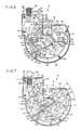
- the front element 34 is formed with an inwardly projecting cylindrical receptacle 88 (Figs. 3 and 4) for receiving the hub 92 of an advancing plate 90.
- the advancing plate 90 (Figs. 8 and 9) is contained within the housing 32 for incrementally advancing the card 14 to display sequentially pairs of images 12.
- the plate 90 has a front face 91 and a rear face 93.
- the hub 92 projects perpendicularly from the face 91 into the receptacle 88, as best seen in Figs. 3 and 4.
- the axis of the hub 92 is perpendicular to the parting plane of the housing 32 and the plate 90 oscillates, of course, about the same axis.
- the plate 90 oscillates between a rest position (shown in Fig. 6) in which the pair of images 12A R , 12A L are viewed through eyepieces 16L, 16R, and an advanced position (Fig. 7) in which images 12B R , 12B L have been rotated into position in front of the eyepieces 16L, 16R.
- the plate 90 has a top trigger engaging portion 94 which projects into and partially across trigger space 86.
- the portion 94 has a top flanged stopping edge 95 and is cut away to define an edge 96 which is perpendicular to the edge 95 and parallel to the sidewall 97 of the housing 32 in the rest position of the plate.
- the cutaway portion of plate 90 extends below cutaway portion 82 of the front element 34 and the position of an image 12 positioned in front of the eyepiece 16L, as best seen in Fig. 6. This configuration of the plate 90 prevents the plate from obstructing the first eyepiece 16L and printed indicia A-G on the card 14 when the plate is in its rest position.
- the balance of the edge 99 of the plate 90 is substantially arcuate and coaxial with the hub 92.
- the plate 90 further includes a boss 100 (Figs. 4, 6 and 7) projecting from the front surface of the plate adjacent the hub 92 and offset slightly to the left and above hub 92 as the plate 90 is viewed in Fig. 6.
- a rectangular window 102 is provided through plate 90, the window 102 being slightly larger than windows 24 and positioned to be in register with an image 12 in front of the eyepiece 16R when the plate 90 is in its rest position, as shown in Fig. 6.
- Three short, arcuate flanges 104, 106, 108 (Fig. 8) extend outwardly from the rear face 93 of plate 90 adjacent its periphery for holding the card 14 in place on the plate 90.
- the flange 104 also serves as a stop which abuts a stop flange 105 on the front element 34 (Figs. 6 and 7) when the plate 90 reaches its fully advanced position, see Fig. 7.
- a series of ridges 110, 112, 114, 116, and 118 are also projecting from the rear face 93 of plate 90 .
- the ridges 110-118 provide sliding surfaces of small contact area with a card 14 allowing the plate 90 to return to its rest position while leaving the card 14 in an advanced position.
- Similar raised ridges 120, 122, 124, and 126 are provided adjacent the semicircular edge of plate 90 for a similar reason.
- a semicircular cutout 128 (Figs. 8 and 9) through the plate 90 is positioned adjacent the ridge 118 and inside the semicircle formed by ridges 110-118.
- a hook 130 projects outwardly from the front face 91 of the plate 90 adjacent the cutout 128 for attachment of a first end 131 of a spring 132 (Fig. 6) thereto.
- the other free end 133 of the spring 132 is connected to an anchor 135 on the front element 34.
- the hook 130 is below hub 92 and on the far side of the axis of oscillation from the anchor 135.
- the spring 132 therefore biases the plate 90 toward the rest position shown in Fig. 6 and returns the plate to its rest position after it has been moved to the advanced position shown in Fig. 7.
- a card engaging means 138 (Figs. 5 and 6-9) is provided on the plate 90 for engaging and rotating the card 14 as the plate moves from its rest position of Fig. 6 to its advanced position of Fig. 7.
- the engaging means 138 includes an elongated cutout portion 140 in which a flexible arm 142 is carried, one end of the arm being integral with the plate 90.
- the arm 142 is substantially coplanar with the plate 90, except for a pawl 144 projecting outwardly from the face 93 of the plate 90 from the opposite end of the arm.
- the pawl 144 has a flat leading face 146 (Fig. 5) which engages an edge of the slot 26 to advance the card 14 when the plate 90 rotates from the rest position of Fig. 6 to the advanced position of Fig. 7.
- the trailing face 148 of the pawl 144 is arcuate in cross section and inclined from the arm 92 towards the face 146.
- the faces 146, 148 thus define a pointed pawl.
- the face 148 because of its slope provides relatively little resistance to disengagement of the pawl 144 from the slot 26 when the plate 90 begins to move back to its rest position under the influence of the spring 132. This easy disengagement is desirable since the card 14 must remain in its advanced position to display the sequential display of images.
- the pawl 144 is inclined at an acute angle 150 (Fig. 5) to the plate.
- the angle 150 is about 70°. Tilting the pawl 144 at such an angle helps grip the card 14 to the face 93 of the plate 90 and hold the card 14 in a desired plane of rotation as plate 90 oscillates towards the advanced position of Fig. 7. Conversely, the tilt of pawl 144 helps disengage the pawl from the slot 26 when the plate 90 begins to oscillate back to its rest position.
- a trigger means 156 (Figs. 6 and 7) is provided to rotate the plate 90 from the rest position of Fig. 6 to the advanced position of Fig. 7 and index the card 14.
- the trigger means 156 includes a cylindrical actuator 158 having a plurality of circular ridges 160 therearound and a plate-like leg 162 depending from the actuator 158.
- the actuator 158 projects substantially vertically upwardly through and above the top flat flange 80 of the finger grip portion 84.
- the leg 162 extends downwardly adjacent the front face of the advancing plate 90 and has a top finger 164 projecting perpendicularly from the leg 162 towards the plate 90 a sufficient distance for engaging the top flat edge 95 of the trigger engaging portion 94 of plate 90, and a lower finger 166 projecting parallel to the plate 90 a sufficient distance for engaging the top of the boss 100, see Fig. 6.
- the leg 162 comprises a horizontal segment 168, an angled segment 169, and a vertical segment 170. Projecting upwardly from the horizontal segment is a stop finger 171 which engages a button 173 on the top wall of the housing in the rest position of the advancing mechamism. When the plate 90 is in its rest position, the flat top edge 95 of the portion 94 engages the top finger 164, and the finger 166 is positioned slightly above the boss 100.
- An opaque mask 172 (Figs. 3, 4, 6, and 7) is provided within the housing 32 in front of the focal plane of the lenses 18R, 18L.
- the preferred position of the mask 172 is immediately adjacent the rear surface of the front face 78.
- the mask 172 has a pair of rectangular openings 174, 176 which correspond to the shape of the windows 24 in the card 14, the openings 174, 176 being slightly larger than the windows 24.
- the openings 174, 176 are a sufficient size and distance in front of the card 14 only to allow viewing of one framed image 12 through each lens 18.
- the mask 172 thereby prevents a user from seeing peripheral parts within the housing 32 that would distract his attention from the viewed image.
- the card 14 is inserted edgewise through the slot 41 of the housing 32 so that the card 14 is received on the face 93 of the plate 80 and cradled thereon by the flanges 104, 106, 108.
- the card 14 is placed on the plate 90 with the lamination 22 flat against the face 93 such that written indicium A on the lamination 20 is visible through cutout portion 82, and the pawl 144 projects into one of the slots 26 of the card 14.
- the card in this position will display the image 12A R to the lens 18R of the eyepiece 16R and the image 12A L to the lens 18L of the eyepiece 16L.
- the housing 32 is then grasped by one or both hands and the rear face 36 is supplied with a source of light, such as ambient room light. Light entering through the transculent rear face 36 of the housing 32 will illuminate the images 12A so that they can be magnified and clearly viewed by one who places lenses 18 in front of his eyes.
- a source of light such as ambient room light.
- the index finger of a trigger hand can be used to depress the actuator 158 without releasing the trigger hand's grasp on the housing 32. Depression of the actuator 158 forces the top finger 164 downwardly on the edge 95 of the plate 90 which begins rotation of the plate in a counterclockwise direction as viewed in Fig. 6. As depression of the actuator 158 continues, the finger 164 slides across the edge 95 towards the edge 96. By the time the finger 164 reaches the end of the edge 95, the lower finger 166 engages the boss 100 to complete oscillation of the plate 90 to the position shown in Fig.
- images 12B R , 12B L are aligned with the lenses 18R, 18L of the eyepieces 16R, 16L.
- the printed indicium B also moves into view through cutaway portion 82. Solid portions of the plate 90 obscure the view of the card 14 through the eyepieces 16 so that no images 12 can be viewed during most of the transition from images 12A to images 12B.
- the flange 104 of the plate 90 comes into contact with the stop 105 when the images 12B and indicium B are so aligned, thereby limiting the forward oscillation of the plate 90.
- the user releases pressure on the actuator 158 by removing the index finger therefrom, and the spring 132 pulls the plate 90 back towards its rest position.
- Return movement of the plate forces the boss 100 upwardly against the finger 166 to move the actuator 158 towards its original, undepressed position.
- the top edge 95 engages the top finger 164 to return the actuator 158 and the leg 162 completely to their original position shown in Fig. 6.
- the plate returns to its rest position, the card 14 is held in its advanced position by detent members 68, 70 which are in register with slots 26b, 26f.
- the window 102 on the plate 90 registers with image 12B R while image 12B L is completely unobscured by the plate 90 so such images can be viewed through the eyepieces.
- the trigger can be repeatedly actuated sequentially to advance the card 14 and view all seven pairs of images 12A-12G with their accompanying written indicia A-G.
Applications Claiming Priority (2)
| Application Number | Priority Date | Filing Date | Title |
|---|---|---|---|
| US06/866,138 US4726653A (en) | 1986-05-22 | 1986-05-22 | Stereoscopic viewer |
| US866138 | 1992-04-09 |
Related Parent Applications (1)
| Application Number | Title | Priority Date | Filing Date |
|---|---|---|---|
| EP87107138.7 Division | 1987-05-18 |
Publications (2)
| Publication Number | Publication Date |
|---|---|
| EP0460713A2 true EP0460713A2 (fr) | 1991-12-11 |
| EP0460713A3 EP0460713A3 (en) | 1992-07-01 |
Family
ID=25346998
Family Applications (2)
| Application Number | Title | Priority Date | Filing Date |
|---|---|---|---|
| EP19910113408 Withdrawn EP0460713A3 (en) | 1986-05-22 | 1987-05-18 | Improved stereoscopic viewer |
| EP87107138A Expired - Lifetime EP0246586B1 (fr) | 1986-05-22 | 1987-05-18 | Appareil de visualisation stéréoscopique |
Family Applications After (1)
| Application Number | Title | Priority Date | Filing Date |
|---|---|---|---|
| EP87107138A Expired - Lifetime EP0246586B1 (fr) | 1986-05-22 | 1987-05-18 | Appareil de visualisation stéréoscopique |
Country Status (14)
| Country | Link |
|---|---|
| US (1) | US4726653A (fr) |
| EP (2) | EP0460713A3 (fr) |
| JP (2) | JPS62287220A (fr) |
| KR (1) | KR950001271B1 (fr) |
| CN (1) | CN1017098B (fr) |
| AT (1) | ATE74445T1 (fr) |
| BR (1) | BR8702617A (fr) |
| CA (1) | CA1336235C (fr) |
| DD (1) | DD256575A5 (fr) |
| DE (1) | DE3777876D1 (fr) |
| ES (1) | ES2030400T3 (fr) |
| IE (1) | IE60079B1 (fr) |
| IN (1) | IN169410B (fr) |
| MX (1) | MX170913B (fr) |
Cited By (1)
| Publication number | Priority date | Publication date | Assignee | Title |
|---|---|---|---|---|
| EP0628853A1 (fr) * | 1993-06-02 | 1994-12-14 | Eastman Kodak Company | Disque stéréoscopique ainsi qu'un appareil de visualisation et une méthode de production d'un tel disque |
Families Citing this family (9)
| Publication number | Priority date | Publication date | Assignee | Title |
|---|---|---|---|---|
| US5101269A (en) * | 1990-09-18 | 1992-03-31 | Eastman Kodak Company | Stereoscopic electronic slide and print viewer |
| WO1998014819A1 (fr) * | 1996-10-04 | 1998-04-09 | Jones Charles W | Livre stereographique |
| US6031662A (en) * | 1998-02-06 | 2000-02-29 | Fisher - Price, Inc. | Convertible binocular/stereoscope device |
| JP3394764B2 (ja) * | 2001-04-09 | 2003-04-07 | 稔 稲葉 | ステレオスライドビューワ |
| JP2010033025A (ja) * | 2008-07-04 | 2010-02-12 | Olympus Corp | 顕微鏡 |
| US8223428B2 (en) | 2008-07-04 | 2012-07-17 | Olympus Corporation | Microscope |
| US9069243B2 (en) * | 2009-03-23 | 2015-06-30 | Imperial Toy, Llc | System and method for generating a three-dimensional image on a pre-printed lined substrate |
| DE102015000354A1 (de) | 2015-01-20 | 2016-07-21 | Can Ansay | An einer Baseballkappe montiretes Smartphone-Stereoskop |
| US11112676B2 (en) * | 2018-03-07 | 2021-09-07 | Hewlett-Packard Development Company, L.P. | Camera lens sliders |
Citations (5)
| Publication number | Priority date | Publication date | Assignee | Title |
|---|---|---|---|---|
| US2511334A (en) * | 1947-04-28 | 1950-06-13 | Wilhelm B Gruber | Stereoscopic viewer |
| US4146303A (en) * | 1976-04-30 | 1979-03-27 | Gakken Co., Ltd. | Stereo-viewer and stereo-sheet to be used for the same |
| DE3122093A1 (de) * | 1981-06-03 | 1982-12-23 | Photo Universal Deuscher KG GmbH & Co, 7012 Fellbach | Stereoskopisches betrachtungsgeraet |
| US4402580A (en) * | 1980-07-31 | 1983-09-06 | Richard Ross | Optical exercising device |
| EP0134871A1 (fr) * | 1983-09-22 | 1985-03-27 | Roger Cuvillier | Visionneuse stéréoscopique |
Family Cites Families (11)
| Publication number | Priority date | Publication date | Assignee | Title |
|---|---|---|---|---|
| US185670A (en) * | 1876-12-26 | Improvement in oil-stoves | ||
| US174902A (en) * | 1876-03-21 | Improvement in machines for assorting temple-teeth | ||
| US175215A (en) * | 1876-03-21 | Improvement in combined office directories and desks | ||
| US171049A (en) * | 1875-12-14 | Improvement in retorts for concentrating sulphuric acid | ||
| US184356A (en) * | 1876-11-14 | Improvement in heating chill-molds | ||
| US189006A (en) * | 1877-03-27 | Improvement in ventilators | ||
| US2189285A (en) * | 1939-01-20 | 1940-02-06 | Wilhelm B Gruber | Stereoscopic viewing device |
| US2674920A (en) * | 1952-07-17 | 1954-04-13 | Three Dimension Company | Stereoscopic viewer |
| GB1251530A (fr) * | 1967-12-21 | 1971-10-27 | ||
| JPS5747813A (en) * | 1980-09-03 | 1982-03-18 | Nippon Steel Corp | Method for selective supply of tuyere gas of refining furnace |
| US4404525A (en) * | 1981-03-03 | 1983-09-13 | American Microsystems, Inc. | Switched capacitor gain stage with offset and switch feedthrough cancellation scheme |
-
1986
- 1986-05-22 US US06/866,138 patent/US4726653A/en not_active Expired - Lifetime
-
1987
- 1987-04-23 IE IE105887A patent/IE60079B1/en not_active IP Right Cessation
- 1987-05-01 IN IN313/MAS/87A patent/IN169410B/en unknown
- 1987-05-12 KR KR1019870004626A patent/KR950001271B1/ko not_active IP Right Cessation
- 1987-05-18 AT AT87107138T patent/ATE74445T1/de not_active IP Right Cessation
- 1987-05-18 EP EP19910113408 patent/EP0460713A3/en not_active Withdrawn
- 1987-05-18 DE DE8787107138T patent/DE3777876D1/de not_active Expired - Lifetime
- 1987-05-18 ES ES198787107138T patent/ES2030400T3/es not_active Expired - Lifetime
- 1987-05-18 EP EP87107138A patent/EP0246586B1/fr not_active Expired - Lifetime
- 1987-05-21 MX MX006585A patent/MX170913B/es unknown
- 1987-05-21 CN CN87103756A patent/CN1017098B/zh not_active Expired
- 1987-05-21 CA CA000537694A patent/CA1336235C/fr not_active Expired - Fee Related
- 1987-05-21 DD DD87303002A patent/DD256575A5/de not_active IP Right Cessation
- 1987-05-21 BR BR8702617A patent/BR8702617A/pt active Search and Examination
- 1987-05-22 JP JP62124124A patent/JPS62287220A/ja active Pending
-
1995
- 1995-10-02 JP JP010395U patent/JPH08592U/ja active Pending
Patent Citations (5)
| Publication number | Priority date | Publication date | Assignee | Title |
|---|---|---|---|---|
| US2511334A (en) * | 1947-04-28 | 1950-06-13 | Wilhelm B Gruber | Stereoscopic viewer |
| US4146303A (en) * | 1976-04-30 | 1979-03-27 | Gakken Co., Ltd. | Stereo-viewer and stereo-sheet to be used for the same |
| US4402580A (en) * | 1980-07-31 | 1983-09-06 | Richard Ross | Optical exercising device |
| DE3122093A1 (de) * | 1981-06-03 | 1982-12-23 | Photo Universal Deuscher KG GmbH & Co, 7012 Fellbach | Stereoskopisches betrachtungsgeraet |
| EP0134871A1 (fr) * | 1983-09-22 | 1985-03-27 | Roger Cuvillier | Visionneuse stéréoscopique |
Cited By (1)
| Publication number | Priority date | Publication date | Assignee | Title |
|---|---|---|---|---|
| EP0628853A1 (fr) * | 1993-06-02 | 1994-12-14 | Eastman Kodak Company | Disque stéréoscopique ainsi qu'un appareil de visualisation et une méthode de production d'un tel disque |
Also Published As
| Publication number | Publication date |
|---|---|
| EP0246586B1 (fr) | 1992-04-01 |
| DE3777876D1 (de) | 1992-05-07 |
| DD256575A5 (de) | 1988-05-11 |
| JPH08592U (ja) | 1996-04-02 |
| ATE74445T1 (de) | 1992-04-15 |
| ES2030400T3 (es) | 1992-11-01 |
| EP0246586A1 (fr) | 1987-11-25 |
| IE871058L (en) | 1987-11-22 |
| CN1017098B (zh) | 1992-06-17 |
| US4726653A (en) | 1988-02-23 |
| CN87103756A (zh) | 1988-03-02 |
| IE60079B1 (en) | 1994-06-01 |
| BR8702617A (pt) | 1988-02-23 |
| JPS62287220A (ja) | 1987-12-14 |
| KR870010884A (ko) | 1987-12-18 |
| MX170913B (es) | 1993-09-22 |
| CA1336235C (fr) | 1995-07-11 |
| KR950001271B1 (ko) | 1995-02-15 |
| IN169410B (fr) | 1991-10-12 |
| EP0460713A3 (en) | 1992-07-01 |
Similar Documents
| Publication | Publication Date | Title |
|---|---|---|
| EP0246586B1 (fr) | Appareil de visualisation stéréoscopique | |
| US6070350A (en) | Display/viewer for multiple, 3D, and other special visual effects | |
| GB2189622A (en) | Toy film projector | |
| US5117339A (en) | Compact combined light and magnifier apparatus for a hand held computer with video screen | |
| US4060929A (en) | Toy detective set | |
| US2853585A (en) | Vending selector button | |
| US1964879A (en) | Picture display device | |
| CA1066096A (fr) | Visionneuse pour microfiches qu'on peut tenir a la main | |
| US5031870A (en) | Display card mounting device | |
| US2916964A (en) | Device for feeding discs in projectors, viewers, and the like | |
| US2570913A (en) | Toy film viewer | |
| US3386195A (en) | Slide tray for projector | |
| US2572602A (en) | Picture viewing device | |
| US6537123B2 (en) | System and method for displaying magnetic devices | |
| US4396262A (en) | Hand held transparency projector with simple advance mechanism | |
| US5881483A (en) | Means for and methods of conveying information to prospective purchasers | |
| JP3068447U (ja) | レ―ザ―ポインタ― | |
| US4685231A (en) | Photographic disc viewer | |
| US3041742A (en) | Selectively operable star finder | |
| JPS5924027Y2 (ja) | 文字表示器付観察装置 | |
| JPS641716Y2 (fr) | ||
| US6463258B1 (en) | Electrical flash card unit and method of use | |
| JPH0676983U (ja) | フィルム等の照明装置 | |
| JPH0254816A (ja) | 表示機能付押ボタンスイッチユニット | |
| JP3947983B2 (ja) | 用途表示部を備えたスイッチハンドル |
Legal Events
| Date | Code | Title | Description |
|---|---|---|---|
| PUAI | Public reference made under article 153(3) epc to a published international application that has entered the european phase |
Free format text: ORIGINAL CODE: 0009012 |
|
| 17P | Request for examination filed |
Effective date: 19910809 |
|
| AC | Divisional application: reference to earlier application |
Ref document number: 246586 Country of ref document: EP |
|
| AK | Designated contracting states |
Kind code of ref document: A2 Designated state(s): AT BE CH DE ES FR GB GR IT LI LU NL SE |
|
| RIN1 | Information on inventor provided before grant (corrected) |
Inventor name: GRESHAM, DAVID M. Inventor name: THALER, MARTIN Inventor name: LEWIS, ALAN G. |
|
| PUAL | Search report despatched |
Free format text: ORIGINAL CODE: 0009013 |
|
| AK | Designated contracting states |
Kind code of ref document: A3 Designated state(s): AT BE CH DE ES FR GB GR IT LI LU NL SE |
|
| RAP1 | Party data changed (applicant data changed or rights of an application transferred) |
Owner name: TYCO INDUSTRIES, INC. |
|
| 17Q | First examination report despatched |
Effective date: 19950105 |
|
| GRAH | Despatch of communication of intention to grant a patent |
Free format text: ORIGINAL CODE: EPIDOS IGRA |
|
| STAA | Information on the status of an ep patent application or granted ep patent |
Free format text: STATUS: THE APPLICATION IS DEEMED TO BE WITHDRAWN |
|
| 18D | Application deemed to be withdrawn |
Effective date: 19960330 |