EP0460606A2 - Card reader-writer - Google Patents
Card reader-writer Download PDFInfo
- Publication number
- EP0460606A2 EP0460606A2 EP91109111A EP91109111A EP0460606A2 EP 0460606 A2 EP0460606 A2 EP 0460606A2 EP 91109111 A EP91109111 A EP 91109111A EP 91109111 A EP91109111 A EP 91109111A EP 0460606 A2 EP0460606 A2 EP 0460606A2
- Authority
- EP
- European Patent Office
- Prior art keywords
- card
- chucking
- card reader
- writer
- writer according
- Prior art date
- Legal status (The legal status is an assumption and is not a legal conclusion. Google has not performed a legal analysis and makes no representation as to the accuracy of the status listed.)
- Granted
Links
Images


Classifications
-
- G—PHYSICS
- G06—COMPUTING; CALCULATING OR COUNTING
- G06K—GRAPHICAL DATA READING; PRESENTATION OF DATA; RECORD CARRIERS; HANDLING RECORD CARRIERS
- G06K13/00—Conveying record carriers from one station to another, e.g. from stack to punching mechanism
- G06K13/02—Conveying record carriers from one station to another, e.g. from stack to punching mechanism the record carrier having longitudinal dimension comparable with transverse dimension, e.g. punched card
- G06K13/08—Feeding or discharging cards
-
- G—PHYSICS
- G06—COMPUTING; CALCULATING OR COUNTING
- G06K—GRAPHICAL DATA READING; PRESENTATION OF DATA; RECORD CARRIERS; HANDLING RECORD CARRIERS
- G06K13/00—Conveying record carriers from one station to another, e.g. from stack to punching mechanism
- G06K13/02—Conveying record carriers from one station to another, e.g. from stack to punching mechanism the record carrier having longitudinal dimension comparable with transverse dimension, e.g. punched card
- G06K13/06—Guiding cards; Checking correct operation of card-conveying mechanisms
- G06K13/063—Aligning cards
Definitions
- the present invention relates to a card reader-writer for transmitting and receiving information to and from magnetic and IC cards.
- the conventional card reader-witer has a card inserting opening in the center of one side of its frame and the card is selectively inserted into this card inserting opening. Magnetic stripes are formed on the top and underside of the card. Take-in rollers for taking the card inserted into the card inserting opening into the card reader-writer are arranged one upon the other in the frame and adjacent to the card inserting opening.
- a group of paired carrying rollers is arranged behind the take-in rollers in the frame in such a way that the paired carrying rollers are opposed to each other in the vertical direction.
- Each of these carrying and take-in rollers is made of rubber or plastics.
- magnetic heads are located adjacent to the carrying rollers, opposing to each other in the vertical direction with a certain magnetic gap interposed between them.
- the carrying and take-in rollers are driven commonly by a motor.
- the card inserted into the card inserting opening is taken into the card reader-writer by the take-in rollers and carried backward between the front paired carrying rollers.
- This card is carried backward by pressing force created between the carrying rollers by springs and by friction created by the carrying rollers rotated.
- the card is carried to the area paired carrying rollers while spreading the upper and lower magnetic heads
- the magnetic heads read information recorded on the magnetic stripe on the card and write information on the magnetic stripe thereon.
- the card is returned to the card inserting opening and then back to the customer.
- the card is frictionally carried using frictional force between the rubber- or plastics-made take-in rollers and between the rubber- or plastics-made carrying rollers and the card. Therefore, the frictional force changes depending upon the surface state of each of the rollers, that of the card and material of which the card is made. In addition, each of the rollers repeats its elastic deformation every time the card is carried between the rollers. As the result, the card carrying velocity cannot be kept certain, thereby preventing reading and writing of magnetic information from being accurately achieved.
- the card is successively carried backward by three pairs of the carrying rollers and every time it is taken between the paired carrying rollers, it is impacted by the rollers and thus vibrated.
- the stability of carrying the card is thus lowered, thereby making it impossible to accurately read and write the magnetic information.
- the magnetic stripe, the embossed portion and the IC node portion are arranged adjacent to one another on the card in the width direction thereof. This allows the card to be sandwiched between the carrying rollers only at such an area of the card that extends about 2 - 3mm from one side edge of the card in the width direction thereof. It is therefore feared that the card carrying capacity of the carrying rollers is further lowered.
- the conventional card reader-writer uses the system of carrying the card by the frictional force created between the rubber-made rollers and the card. This makes it difficult to carry the card at a certain velocity. As the result, reliable reading and writing of information cannot be attained.
- the object of the present invention is therefore to provide a card reader-writer capable of being more easily maintained but making it unnecessary to use any card carrying system which uses frictional force created by the rollers and accurately reading and writing information on a card.
- a card reader-writer comprising a body having a card inserting opening into which a card to which reading and writing of information can be made is inserted; means arranged in the body to reads and write information from and on the card; means for carrying the card which is inserted into the card inserting opening to the read/write means, said carrying means including means for chucking the card and means for moving the chucking means on a certain passage; and means for adjusting or correcting the position of the card chucked by the chucking means.
- the card inserted into the card inserting opening is chucked by the chucking means.
- This card chucking means is moved along the certain passage by the moving means.
- the card moving velocity is determined in this case only by the velocity at which the card chucking means is moved by the moving means. Therefore, it is easier to make certain this velocity of moving the card chucking means. A more stable card carrying can be thus attained.
- the present invention does not employ the system of carrying the card by the frictional force created by the rubber-made rollers, for example. Even when the card reader-writer is used for a long time, therefore, its capacity of carrying the card cannot be lowered.
- FIG. 1 shows the main portion of the card reader-writer according to a first embodiment of the present invention.
- This card reader-writer has a frame or body 1 shaped like a rectangle when viewed from the top thereof.
- the frame 1 comprises side plates 2a and 2b arranged parallel to each other and plural coupling rods 3 for coupling the side plates 2a and 2b parallel to each other.
- a front panel (not shown) is located a little before right end faces of the side plates 2a and 2b in Fig. 1 and a card inserting opening (not shown) is formed at the front panel.
- a card 4 is selectively inserted into the card reader-writer through the card inserting opening.
- the card 4 is a magnetic one into which an IC is incorporated.
- Two guide rods 5a and 5b parallel to each other are located adjacent to the inner face of the side plate 2b and parallel to the direction in which the card 4 is inserted into the card reader-writer.
- a card chucking unit 6 which forms a carriage 6A is freely movably supported by the guide rods 5a and 5b.
- the card chucking unit 6 chucks one long edge portion of the card 4 in the thickness direction thereof when the card 4 is inserted into the card inserting opening longer than a certain length.
- Fig. 2 shows the card chucking unit 6 more concretely.
- the card chucking unit 6 has a base 7 freely movably supported by the guide rods 5a and 5b. That side of the base 7 which is opposed to the side plate 2b is provided with a lower claw 8 which serves as a chucking claw.
- An upper claw 9 is located above the lower claw 8 and base portions 10 of this upper claw 9 are freely swingably attached to the base 7 by means of pins 11.
- Pre-load springs 12 which are of the torsion coil springs are interposed between the upper claw 9 and the base 7 to create a certain chucking force between the upper 9 and the lower claw 8.
- Pins 13a and 13b are formed on the top of the upper claw 9, erecting parallel to the side plate 2b of the frame 1 and then bending toward it.
- the upper claw 9 is opened and closed relative to the lower claw 8 by the opening and closing system 14 through the pins 13a and 13b.
- the opening and closing system 14 has a lever 15 located above and parallel to the guide rod 5a and selectively contacted with the undersides of the pins 13a and 13b.
- the lever 15 is supported by a rotary member 16 extending the inner face of the side plate 2b. Both ends of the rotary member 16 are supported by bearings 18a and 18b through pins 17.
- the bearings 18a and 18b are fixed to the inner face of the side plate 2b.
- a shaft (not shown) is projected to the side plate 2b from the center of that face of the rotary member 16 which is opposed to the side plate 2b, and a roller 19 is attached to this shaft.
- the roller 19 is contacted with an eccentric cam 20, which is connected to the rotating shaft of a motor 21.
- the unit 22A Located along the inner face of the side plate 2a is an unit 22A for adjusting or correcting the position of the card.
- the unit 22A has a guide member 22 for guiding the other free long edge portion of the card 4 which is not chucked by the card chucking unit 6 to position the card 4 in the width direction thereof.
- the guide member 22 is supported by support levers 23 and 24.
- Pins 25 and 26 are projected from the support levers 23 and 24, which are freely swingably supported by a support member (not shown) through the pins 25 and 26.
- Urging springs 27 and 28 are interposed between the side plate 2a and the lower end portion of the support plate 24 and between the side plate 2a and the lower end portion of the support lever 25, respectively, to swing the support levers 24 and 25 toward the guide rod 5a.
- a motor 29 is located between the guide rod 5a and the guide member 22 and below them.
- the rotation force of the motor 29 is transmitted to a belt 35 via a belt 30, a pulley 31, a belt 32 and pulleys 33, 34.
- the belt 35 is stretched between the pulley 34 and another pulley 36 along the underside of the guide rod 5a.
- a part of the belt 35 is connected to the base 7 of the card chucking unit 6 through a coupling means (not shown).
- the motor 29, the belts and the pulleys mentioned above therefore form a drive system for moving the card chucking unit 6 along the guide rods 5a and 5b.
- Magnetic heads 38 and 39 are opposed to each other in the vertical direction between the guide rod 5a and the guide member 22, having such a certain gap 40 between them as allows them to contact magnetic stripes on the top and underside of the card 4. They are supported by suspensions 41 and 42 so as to move in their rolling direction and in the direction of the gap 40 between them.
- the suspensions 41 and 42 are arranged to add contact pressure to them through plate or coil springs so that they may be stably contacted with the card 4.
- the card chucking unit 6 When it is under normal state, the card chucking unit 6 is waiting at such a position as shown in Fig. 1 on the side of the card inserting opening. When it is under this waiting state, the lower and upper claws 8 and 8 are kept open by the opening and closing system 14.
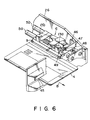
- Figs. 3 through 6 show main portions of the card reader-writers which are variations from the first embodiment of the present invention. Same components as those shown in Fig. 1 will be denoted by same reference numerals and description on these components will be omitted.
- the card reader-writer When arranged in this manner, the card reader-writer can attain same merits as those in the one shown in Fig. 1.
- a elastic member 43 such as rubber is attached to the chucking area of the upper claw 9 of the card chucking unit 6 and in the case of a third variation shown in Fig. 5, elastic matters 43 and 44 are achieved to chucking areas of the upper and lower claws 9 and 8.
- the card 4 When arranged in this manner, the card 4 can be more stably chucked between the upper and the lower claw due to the elastic matter 43 or elastic matters 43 and 44, thereby enabling the card 4 to be more stably conveyed, too.
- a system 46 for forcedly releasing the chucking operation of the card chucking unit 6 is located before the position at which the card chucking unit 6 is waiting, that is, on the side of a card inserting opening 45.
- the card 4 can be easily pulled out of the card reader-writer even if the card chucking unit 6 should not be opened because of power stop, for example, when the card 4 chucked by the card chucking unit 6 is returned to the waiting position of the system 6.
- the projection 13a is contacted with the roller 48 and lifted upward by the roller 48 as the card 4 is further pulled in the same direction.
- the upper claw 9 is swung to thereby allow the card 4 to be pulled out of the card reader-writer.
- Fig. 7 shows the card reader-writer according to a second embodiment of the present invention.
- This second embodiment of the present invention is designed for use with magnetic cards.
- a front panel 49 is located in front of the side plates 2a and 2b which form the frame 1.
- the front panel 49 is provided with a card inserting opening 45 through which the card 4 is inserted into the card reader-writer.
- Two guide rods 5a and 5b parallel to each other are arranged adjacent to the inner face of the side plate 2b and parallel to the card-inserting direction.
- the carriage 6A provided with the card chucking unit 6 is freely movably supported by the guide rods 5a and 5b.
- the card chucking unit 6 associates with the opening and closing system 14 to chuck the card 4 along the long one edge portion thereof in the thickness direction thereof.
- the base 7 of the card chucking unit 6 is freely movably supported by the guide rods 5a and 5b.
- the lower claw 8 is fixed to the base 7 and the upper claw 9 is located above the lower claw 8 and the base end of the upper claw 9 is freely swingably supported by the base 7.
- the upper claw 9 is urged toward the lower claw or in the closing direction by the urging springs.
- the pins 13a and 13b are mounted on the top of the portion 9A of the upper claw 9, erecting upward and parallel to the side plate 2b.
- the pins 13a and 13b are protruded toward the side plate 2b, and bearings 13c and 13d are mounted on the pins 13a and 13b, respectively.
- the upper claw 9 is controlled to swing toward and from the lower claw 8 by the opening and closing system 14 through the bearings 13c and 13d.
- the opening and closing system 14 includes the lever 15 and a stepping motor 52.
- the lever 15 is located above and parallel to the guide rod 5a and contacted with the undersides of the bearings 13c and 13d. Further, the lever 15 is attached to the rotary member 16 which extends along the inner face of the side plate 2b and which is freely swingably supported by the support members 18a, 18b and pins 18c, 18d.
- the guide member 22 for guiding the other free long edge portion of the card 4 to position the card 4 in the width direction thereof.
- a elastic sheet 22a having high coefficient of friction such as rubber is attached to the surface of the guide member 22, which contacts the side surface of the edge portion of the card 4, by adhesion.
- the guide member 22 is supported by a support lever 55, which is pivoted on the side plate 2a by mounting plates 55b, 55c and pins 55a.
- a drive solenoid 56 is connected to the lower end of the support lever 55 and the guide member 22 is driven by the solenoid 56.
- the motor 29 for conveying the card 4 is arranged below the guide rod 5a.
- the rotation force of this motor 29 is transmitted through the belts and the pulleys, as seen in the case of the first embodiment, to move the card chucking unit 6 along the guide rods 5a and 5b.
- a prehead 61 which is contacted with magnetic stripes on the underside (or top) of the card 4 to detect magnetism is located along and adjacent to the guide rod 5a and a magnetic head 57 which is contacted with magnetic stripes on the underside (or top) of the card 4 to read and write information is also located along and adjacent to the guide rod 5a.
- a card detecting sub-sensor (SW) 60, the prehead (PHD) 61 and a first card sensor (PD1) 62 which form a card checking unit for previously examining the card 4 inserted are arranged adjacent to the card inserting opening 45 of the card reader-writer.
- the card detecting sub-sensor 60 detects whether or not the card inserted has a predetermined width.
- the prehead 61 detects the magnetic stripes on the card 4 to confirm the direction in which the card 4 is directed.
- the first card sensor 62 detects the insertion of the card 4.
- a first carriage sensor (CRS1) 63 is arranged adjacent to the card checking unit to detect the position of the rear end of the retreated carriage 6A.
- a stopper solenoid (SOL1) 64 is arranged in front of the sensor 63 to prevent wrong cards from being inserted into the card reader-writer and to define the position of the card inserted.
- a card position adjusting section is located in front of the stopper solenoid 64.
- the card position adjusting section includes the card position adjusting solenoid (SOL2) 56, a second carriage sensor (CRS2) 66 and second and third card sensors (PD2 and PD3) 67 and 68.
- the second and third card sensors 67 and 68 are located one after another and adjacent to each other.
- the card 4 adjusted in position is detected by the second card sensor 67 to stop the advancing carriage 6A and the accurate relative positions of the card and the carriage are detected by the third card sensor 68 and the second carriage sensor 66 to position the card 4.
- the read/write and start position of the card 4 is set by the third card sensor 68.
- the card position adjusting solenoid (SOL2) 56 drives the guide member 22 to urge the card 4, which is in a position to be adjusted, traverse to adjust the position of the card 4 in the traverse direction.
- a fourth card sensor (PD4) 69 and a read/write head 57 are arranged in front of the card position adjusting section.
- the fourth card sensor 69 detects the card 4
- the read/write head 57 starts its reading and writing relative to the magnetic stripes on the card 4.
- the stepping motor (SMOT) 52 is arranged in front of and above the read/write head 57 and the carriage moving motor (CMOT) 29 is arranged below the read/write head 57.
- these sensors and actuators are connected to a controller 70 provided with a CPU.
- the carriage 6A provided with the card chucking unit 6 is waiting on the side of the card inserting opening 45 under normal state.
- the card chucking unit 6 is kept open.
- the state of the card 4 is detected by the card width detecting sub-sensor (SW) 60, the prehead (PHD) 61 and the first card sensor (PD1) 62. Signals applied from these sensors are sent to the controller 70 and when it is confirmed that the card is normal or right, the controller 70 makes the stopper solenoid (SOL1) 64 operative to open the card passage and half rotate the stepping motor 52 of the opening and closing system 14.
- the lever 15 is thus lowered and the card chucking unit 6 is closed to chuck the one long edge portion of the card 4 between the upper 9 and the lower claw 8 with a certain force.
- the motor 29 starts it rotation in the forward direction (MCF).
- the card chucking unit 6 is thus moved forward and the card 4 is also moved forward.
- the second card sensor (PD2) 67 detects the card 4 and the motor 29 is stopped while the stopper solenoid 64 is turned off in response to signal applied from the solenoid 67.
- the carriage 6A and the card 4 are then moved forward by inertia and when the third card sensor 68 detects the card 4, the motor 29 rotates in the backward direction (MCB) to stop the carriage 6A at the read/write and start position.
- the card holding solenoid 56 is made operative to swing the guide member 22, thereby adjusting the position of the card 4 in the traverse direction while holding the card 4 at the certain position (or read/write and start position).
- the stepping motor 52 operates to open the card chucking unit 6 and the motor 29 is then rotated backward to position the carriage 6A.
- the motor 29 is controlled this time in response to signal applied from the second carriage sensor 66.
- the card holding solenoid is turned off and the stepping motor again operates to close the card chucking unit 6.
- the motor 29 rotates in the forward direction (MCF) to move the card 4 forward. And the card 4 passes on the magnetic head 57 arranged on the card conveying passage.
- the fourth card sensor 69 detects the card 4 in this case, writing (or reading) of information is started on the magnetic stripes on the underside (or top) of the card 4.
- the first carriage sensor 63 detects the carriage 6A and the stepping motor 52 is half rotated to open the card chucking unit 6. A part of the card 4 is projected outside from the card inserting opening 45 under this state. Therefore, the card 4 can be pulled out of the card reader-writer by hand.
- the magnetic head is shown as an element for transmitting and receiving information to and from the card.
- a connective system for transmitting and receiving signals is provided in addition to the magnetic head.
- the urging springs for adding chucking force to the card chucking unit are selected depending upon what type of the card chucking unit is employed.
Abstract
Description
- The present invention relates to a card reader-writer for transmitting and receiving information to and from magnetic and IC cards.
- Automatic monetary machines such as the cash dispenser (CD) and the automatic teller machine (ATM) which use magnetic and IC cards as their information recording media have been developed to save and speed up business works at the front of financial agencies such as the bank, post office and credit bank.
- These automatic monetary machines need no person attended or in charge. Therefore, they have been improved day by day to need no maintenance and enhance their reliability so as to allow any customer to use them with a sense of relief even on holiday. Particularly when the card reader-writer is jammed by the card on holiday, the situation becomes critical because the card cannot be returned to the customer. In order to avoid this, therefore, the card reader-writer is provided with various measures.
- The conventional card reader-witer has a card inserting opening in the center of one side of its frame and the card is selectively inserted into this card inserting opening. Magnetic stripes are formed on the top and underside of the card. Take-in rollers for taking the card inserted into the card inserting opening into the card reader-writer are arranged one upon the other in the frame and adjacent to the card inserting opening.
- On the other hand, a group of paired carrying rollers is arranged behind the take-in rollers in the frame in such a way that the paired carrying rollers are opposed to each other in the vertical direction. Each of these carrying and take-in rollers is made of rubber or plastics. Further, magnetic heads are located adjacent to the carrying rollers, opposing to each other in the vertical direction with a certain magnetic gap interposed between them. The carrying and take-in rollers are driven commonly by a motor.
- The card inserted into the card inserting opening is taken into the card reader-writer by the take-in rollers and carried backward between the front paired carrying rollers. This card is carried backward by pressing force created between the carrying rollers by springs and by friction created by the carrying rollers rotated. In this case, the card is carried to the area paired carrying rollers while spreading the upper and lower magnetic heads When the card passes between the magnetic heads in this manner, the magnetic heads read information recorded on the magnetic stripe on the card and write information on the magnetic stripe thereon. When a series of these processes is finished, the card is returned to the card inserting opening and then back to the customer.
- In the case of the conventional card reader-writer arranged as described above, however, the card is frictionally carried using frictional force between the rubber- or plastics-made take-in rollers and between the rubber- or plastics-made carrying rollers and the card. Therefore, the frictional force changes depending upon the surface state of each of the rollers, that of the card and material of which the card is made. In addition, each of the rollers repeats its elastic deformation every time the card is carried between the rollers. As the result, the card carrying velocity cannot be kept certain, thereby preventing reading and writing of magnetic information from being accurately achieved.
- Further, the card is successively carried backward by three pairs of the carrying rollers and every time it is taken between the paired carrying rollers, it is impacted by the rollers and thus vibrated. The stability of carrying the card is thus lowered, thereby making it impossible to accurately read and write the magnetic information.
- Furthermore, when the carrying rollers are used for a long time without adding any maintenance to them, dust, oil and the others adhere to their surface to thereby lower their card carrying capacity. In the worst case, they cannot carry the card.
- In the case of the IC-incororated card, the magnetic stripe, the embossed portion and the IC node portion are arranged adjacent to one another on the card in the width direction thereof. This allows the card to be sandwiched between the carrying rollers only at such an area of the card that extends about 2 - 3mm from one side edge of the card in the width direction thereof. It is therefore feared that the card carrying capacity of the carrying rollers is further lowered.
- As described above, the conventional card reader-writer uses the system of carrying the card by the frictional force created between the rubber-made rollers and the card. This makes it difficult to carry the card at a certain velocity. As the result, reliable reading and writing of information cannot be attained.
- The object of the present invention is therefore to provide a card reader-writer capable of being more easily maintained but making it unnecessary to use any card carrying system which uses frictional force created by the rollers and accurately reading and writing information on a card.
- This object of the present invention can be achieved by a card reader-writer comprising a body having a card inserting opening into which a card to which reading and writing of information can be made is inserted; means arranged in the body to reads and write information from and on the card; means for carrying the card which is inserted into the card inserting opening to the read/write means, said carrying means including means for chucking the card and means for moving the chucking means on a certain passage; and means for adjusting or correcting the position of the card chucked by the chucking means.
- According to the present invention, the card inserted into the card inserting opening is chucked by the chucking means. This card chucking means is moved along the certain passage by the moving means. The card moving velocity is determined in this case only by the velocity at which the card chucking means is moved by the moving means. Therefore, it is easier to make certain this velocity of moving the card chucking means. A more stable card carrying can be thus attained.
- Further, the present invention does not employ the system of carrying the card by the frictional force created by the rubber-made rollers, for example. Even when the card reader-writer is used for a long time, therefore, its capacity of carrying the card cannot be lowered.
- This invention can be more fully understood from the following detailed description when taken in conjunction with the accompanying drawings, in which:
- Fig. 1 is a perspective view showing the main portion of the card reader-writer according to a first embodiment of the present invention partly cut away;
- Fig. 2 is a perspective view showing a card chucking system incorporated into the main portion of the card reader-writer shown in Fig. 1;
- Figs. 3 through 5 are perspective views showing variations of the card chucking system in the card reader-writer;
- Fig. 6 is a perspective view showing the main portion of a further variation of the card reader-writer;
- Fig. 7 is a plan showing the main portion of the card reader-wirter according to a second embodiment of the present invention;
- Fig. 8 schematically shows the arrangement of sensors and actuators in the card reader-writer;
- Fig. 9 is a block diagram showing a control section in the card reader-writer; and
- Fig. 10 is a timing chart showing how the sensors and the actuators in the card reader-writer are made operative.
- Some embodiments of the present invention will be described with reference to the accompanying drawings. Fig. 1 shows the main portion of the card reader-writer according to a first embodiment of the present invention.
- This card reader-writer has a frame or
body 1 shaped like a rectangle when viewed from the top thereof. Theframe 1 comprisesside plates 2a and 2b arranged parallel to each other andplural coupling rods 3 for coupling theside plates 2a and 2b parallel to each other. - A front panel (not shown) is located a little before right end faces of the
side plates 2a and 2b in Fig. 1 and a card inserting opening (not shown) is formed at the front panel. Acard 4 is selectively inserted into the card reader-writer through the card inserting opening. Thecard 4 is a magnetic one into which an IC is incorporated. - Two
guide rods side plate 2b and parallel to the direction in which thecard 4 is inserted into the card reader-writer. Acard chucking unit 6 which forms acarriage 6A is freely movably supported by theguide rods - Associating with an opening and closing
unit 14 which will be described later, thecard chucking unit 6 chucks one long edge portion of thecard 4 in the thickness direction thereof when thecard 4 is inserted into the card inserting opening longer than a certain length. Fig. 2 shows thecard chucking unit 6 more concretely. Thecard chucking unit 6 has abase 7 freely movably supported by theguide rods base 7 which is opposed to theside plate 2b is provided with alower claw 8 which serves as a chucking claw. Anupper claw 9 is located above thelower claw 8 andbase portions 10 of thisupper claw 9 are freely swingably attached to thebase 7 by means of pins 11.Pre-load springs 12 which are of the torsion coil springs are interposed between theupper claw 9 and thebase 7 to create a certain chucking force between the upper 9 and thelower claw 8. - The upper and
lower claws card 4 is chucked between the upper and the lower claw over several millimeters in the width direction of thecard 4, leaving a length of thecard 4 not chucked in the longitudinal direction thereof so as to project it outside from the card inserting opening to allow the user to pick up and pull it out of the card inserting opening by his fingers. Practically, thecard 4 has on it magnetic stripes extending adjacent and parallel to its long one edge portion. Therefore, the chucking areas of the upper andlower claws card 4 between the claws, leaving the stripes portion thereof not chucked, or more preferably chuck two thirds of the edge thereof except the striped portion thereof.Pins upper claw 9, erecting parallel to theside plate 2b of theframe 1 and then bending toward it. Theupper claw 9 is opened and closed relative to thelower claw 8 by the opening andclosing system 14 through thepins - The opening and
closing system 14 has alever 15 located above and parallel to theguide rod 5a and selectively contacted with the undersides of thepins lever 15 is supported by arotary member 16 extending the inner face of theside plate 2b. Both ends of therotary member 16 are supported bybearings 18a and 18b throughpins 17. Thebearings 18a and 18b are fixed to the inner face of theside plate 2b. A shaft (not shown) is projected to theside plate 2b from the center of that face of therotary member 16 which is opposed to theside plate 2b, and aroller 19 is attached to this shaft. Theroller 19 is contacted with aneccentric cam 20, which is connected to the rotating shaft of amotor 21. When themotor 21 is half rotated causing theroller 19 to be contacted with that face of theeccentric cam 20 which is located on its long diameter axis, therefore, therotary member 16 is swung round thepins 17. Thelever 15 is thus contacted with at least thepin 13b to push it upward. Theupper claw 9 is thus swung against the urging springs 12 by thepin 13b. As the result, thecard 4 chucked between the upper andlower claws motor 21 is further half rotated, that face of theeccentric cam 20 which is located on its short diameter axis is contacted with theroller 19. As the result, therotary member 16 is reversely swung causing the lower andupper claws card 4 between them. The opening andclosing system 14 is made operative as described above to open and close thecard chucking unit 6. - Located along the inner face of the side plate 2a is an
unit 22A for adjusting or correcting the position of the card. Theunit 22A has aguide member 22 for guiding the other free long edge portion of thecard 4 which is not chucked by thecard chucking unit 6 to position thecard 4 in the width direction thereof. Theguide member 22 is supported bysupport levers Pins pins support plate 24 and between the side plate 2a and the lower end portion of thesupport lever 25, respectively, to swing the support levers 24 and 25 toward theguide rod 5a. - A
motor 29 is located between theguide rod 5a and theguide member 22 and below them. The rotation force of themotor 29 is transmitted to abelt 35 via abelt 30, apulley 31, abelt 32 and pulleys 33, 34. Thebelt 35 is stretched between the pulley 34 and anotherpulley 36 along the underside of theguide rod 5a. A part of thebelt 35 is connected to thebase 7 of thecard chucking unit 6 through a coupling means (not shown). Themotor 29, the belts and the pulleys mentioned above therefore form a drive system for moving thecard chucking unit 6 along theguide rods -
Magnetic heads guide rod 5a and theguide member 22, having such acertain gap 40 between them as allows them to contact magnetic stripes on the top and underside of thecard 4. They are supported bysuspensions gap 40 between them. Thesuspensions card 4. - Sensors and a control circuit are not shown in Fig. 1 but they cooperate with one another to serve as will be described later.
- The operation of the card reader-writer which is arranged as described above will be described.
- When it is under normal state, the
card chucking unit 6 is waiting at such a position as shown in Fig. 1 on the side of the card inserting opening. When it is under this waiting state, the lower andupper claws closing system 14. - When the
card 4 is inserted into the card reader-writer through the card inserting opening and its one long edge portion is positioned between the upper 9 and thelower claw 8 over its certain length, this state is detected by the sensor. Themotor 21 of the opening andclosing system 14 is half rotated in responsive to output applied from the sensor. Thelever 15 is thus lowered and theupper claw 9 is swung by the urging springs 12. As the result, the long one edge portion of thecard 4 is chucked between the upper 9 and thelower claw 8 with certain force. - When this card chucking operation is finished, the
motor 29 starts its rotation. Thebelt 35 is thus run by this rotation of themotor 29. Thecard chucking unit 6 is therefore moved in a direction shown by an arrow A in Fig. 1, causing thecard 4 to be moved in the same direction. The vibration of thecard 4 which is likely to be caused in a direction vertical to the card-conveying direction is prevented by theguide member 22, so that thecard 4 can be stably conveyed. When thecard 4 passes between themagnetic heads card 4. - When the
card 4 is moved to a predetermined position, this state is detected by the sensor (not shown). Themotor 29 is reversely rotated responsive to output applied from the sensor. When thecard chucking unit 6 is thus returned to its original position, the opening andclosing system 14 is made operative to half rotate theeccentric cam 20. This causes thelever 15 to lift theupper claw 9, so that thecard 4 can be released from the chucking force between the lower 8 and theupper claw 9. A part of thecard 4 is kept projected outside from the card inserting opening till then. Thecard 4 can be therefore pulled out of the card reader and writer by fingers. - Figs. 3 through 6 show main portions of the card reader-writers which are variations from the first embodiment of the present invention. Same components as those shown in Fig. 1 will be denoted by same reference numerals and description on these components will be omitted.
- In the case of a first variation shown in Fig. 3, the position of the card inserting opening is shifted from that of the one shown in Fig. 1 by 90° and the direction in which the
card chucking unit 6 is moved is also shifted from that in Fig. 1 by 90°. And one short edge portion of thecard 4 is chucked between the lower 8 and theupper claw 9 of thecard chucking unit 6. - When arranged in this manner, the card reader-writer can attain same merits as those in the one shown in Fig. 1.
- In the case of a second variation shown in Fig. 4, a
elastic member 43 such as rubber is attached to the chucking area of theupper claw 9 of thecard chucking unit 6 and in the case of a third variation shown in Fig. 5,elastic matters lower claws - When arranged in this manner, the
card 4 can be more stably chucked between the upper and the lower claw due to theelastic matter 43 orelastic matters card 4 to be more stably conveyed, too. - In the case of a further variation shown in Fig. 6, a
system 46 for forcedly releasing the chucking operation of thecard chucking unit 6 is located before the position at which thecard chucking unit 6 is waiting, that is, on the side of acard inserting opening 45. - The releasing
system 46 comprises asupport member 47 which is fixed to the inner face of theside plate 2b at its base end and which is projected above theguide rods roller 48 attached to the free end of thesupport member 47. Theroller 48 is freely rotatably supported by ashaft 49 which is attached to the free end of thesupport member 47 in such a way that the axial center line of theshaft 49 crosses theguide rod 5a in a direction perpendicular to the direction in which theguide rod 5a extends. Further, theroller 48 is also attached to theshaft 49 in such a way that the highest outer circumference of theroller 48 is higher than the height of theprojection 13a of thecard chucking unit 6 by about the thickness of thecard 4. - When arranged in this manner. the
card 4 can be easily pulled out of the card reader-writer even if thecard chucking unit 6 should not be opened because of power stop, for example, when thecard 4 chucked by thecard chucking unit 6 is returned to the waiting position of thesystem 6. When thecard 4 is pulled in a direction shown by an arrow B in Fig. 6 in this case, theprojection 13a is contacted with theroller 48 and lifted upward by theroller 48 as thecard 4 is further pulled in the same direction. As the result, theupper claw 9 is swung to thereby allow thecard 4 to be pulled out of the card reader-writer. - Fig. 7 shows the card reader-writer according to a second embodiment of the present invention. This second embodiment of the present invention is designed for use with magnetic cards.
- As shown in Fig. 7, a
front panel 49 is located in front of theside plates 2a and 2b which form theframe 1. Thefront panel 49 is provided with acard inserting opening 45 through which thecard 4 is inserted into the card reader-writer. - Two
guide rods side plate 2b and parallel to the card-inserting direction. Thecarriage 6A provided with thecard chucking unit 6 is freely movably supported by theguide rods - When the
card 4 is inserted into thecard inserting opening 45 over a certain length thereof, thecard chucking unit 6 associates with the opening andclosing system 14 to chuck thecard 4 along the long one edge portion thereof in the thickness direction thereof. Thebase 7 of thecard chucking unit 6 is freely movably supported by theguide rods lower claw 8 is fixed to thebase 7 and theupper claw 9 is located above thelower claw 8 and the base end of theupper claw 9 is freely swingably supported by thebase 7. Similarly to the first embodiment of the present invention, theupper claw 9 is urged toward the lower claw or in the closing direction by the urging springs. Further, thepins portion 9A of theupper claw 9, erecting upward and parallel to theside plate 2b. Thepins side plate 2b, andbearings 13c and 13d are mounted on thepins upper claw 9 is controlled to swing toward and from thelower claw 8 by the opening andclosing system 14 through thebearings 13c and 13d. - The opening and
closing system 14 includes thelever 15 and a steppingmotor 52. Thelever 15 is located above and parallel to theguide rod 5a and contacted with the undersides of thebearings 13c and 13d. Further, thelever 15 is attached to therotary member 16 which extends along the inner face of theside plate 2b and which is freely swingably supported by thesupport members 18a, 18b andpins 18c, 18d. - The stepping
motor 52 is attached to an intermediate plate 2c located substantially in the center of theframe 1, and a rotating shaft 52a is projected from the steppingmotor 52 to theside plate 2b. Apulley 53 and a cam shaft 54 are freely rotatably arranged parallel to the steppingmotor 52 and the rotating shaft 54a of the steppingmotor 52, thepulley 53 and the cam shaft 54 are connected to one another bybelts - The
eccentric cam 20 is attached to the cam shaft 54 and the cam face of thiseccentric cam 20 is contacted with one edge portion of therotary member 16. When the steppingmotor 52 is rotated and that outer circumference of theeccentric cam 20 which is on its larger-diameter line is thus contacted with the edge of therotary member 16, therefore, the rotary member is swung causing thelever 15 to be contacted with at least the bearing 13d to lift the bearing 13d. When the bearing 13d is thus lifted, thecard 4 chucked between the upper and the lower claw of thecard chucking unit 6 is released. When the steppingmotor 52 is further half rotated, that outer circumference of theeccentric cam 20 which is on its smaller-diameter line is contacted with the edge of therotary member 16. As the result, thecard 4 is chucked between the upper and the lower claw of thecard chucking unit 6. The opening andclosing system 14 is operated in this manner to open and close thecard chucking unit 6. - Located along the inner face of the side plate 2a is the
guide member 22 for guiding the other free long edge portion of thecard 4 to position thecard 4 in the width direction thereof. A elastic sheet 22a having high coefficient of friction such as rubber is attached to the surface of theguide member 22, which contacts the side surface of the edge portion of thecard 4, by adhesion. Theguide member 22 is supported by asupport lever 55, which is pivoted on the side plate 2a by mountingplates 55b, 55c and pins 55a. Adrive solenoid 56 is connected to the lower end of thesupport lever 55 and theguide member 22 is driven by thesolenoid 56. - The
motor 29 for conveying thecard 4 is arranged below theguide rod 5a. The rotation force of thismotor 29 is transmitted through the belts and the pulleys, as seen in the case of the first embodiment, to move thecard chucking unit 6 along theguide rods - A
prehead 61 which is contacted with magnetic stripes on the underside (or top) of thecard 4 to detect magnetism is located along and adjacent to theguide rod 5a and amagnetic head 57 which is contacted with magnetic stripes on the underside (or top) of thecard 4 to read and write information is also located along and adjacent to theguide rod 5a. - Sensors and actuators incorporated into the second embodiment of the card reader-writer will be described referring to Figs. 8 and 9.
- A card detecting sub-sensor (SW) 60, the prehead (PHD) 61 and a first card sensor (PD1) 62 which form a card checking unit for previously examining the
card 4 inserted are arranged adjacent to thecard inserting opening 45 of the card reader-writer. Thecard detecting sub-sensor 60 detects whether or not the card inserted has a predetermined width. Theprehead 61 detects the magnetic stripes on thecard 4 to confirm the direction in which thecard 4 is directed. Thefirst card sensor 62 detects the insertion of thecard 4. - A first carriage sensor (CRS1) 63 is arranged adjacent to the card checking unit to detect the position of the rear end of the retreated
carriage 6A. A stopper solenoid (SOL1) 64 is arranged in front of thesensor 63 to prevent wrong cards from being inserted into the card reader-writer and to define the position of the card inserted. - A card position adjusting section is located in front of the
stopper solenoid 64. The card position adjusting section includes the card position adjusting solenoid (SOL2) 56, a second carriage sensor (CRS2) 66 and second and third card sensors (PD2 and PD3) 67 and 68. The second andthird card sensors card 4 adjusted in position is detected by thesecond card sensor 67 to stop the advancingcarriage 6A and the accurate relative positions of the card and the carriage are detected by thethird card sensor 68 and thesecond carriage sensor 66 to position thecard 4. The read/write and start position of thecard 4 is set by thethird card sensor 68. The card position adjusting solenoid (SOL2) 56 drives theguide member 22 to urge thecard 4, which is in a position to be adjusted, traverse to adjust the position of thecard 4 in the traverse direction. - A fourth card sensor (PD4) 69 and a read/
write head 57 are arranged in front of the card position adjusting section. When thefourth card sensor 69 detects thecard 4, the read/write head 57 starts its reading and writing relative to the magnetic stripes on thecard 4. - The stepping motor (SMOT) 52 is arranged in front of and above the read/
write head 57 and the carriage moving motor (CMOT) 29 is arranged below the read/write head 57. - As shown in Fig. 9, these sensors and actuators are connected to a
controller 70 provided with a CPU. - The operation of the card reader-writer which is arranged as described above will be described with reference to a time chart shown in Fig. 10.
- The
carriage 6A provided with thecard chucking unit 6 is waiting on the side of thecard inserting opening 45 under normal state. When thecarriage 6A is under this waiting state, thecard chucking unit 6 is kept open. When thecard 4 is inserted into thecard inserting opening 45 under this state, the state of thecard 4 is detected by the card width detecting sub-sensor (SW) 60, the prehead (PHD) 61 and the first card sensor (PD1) 62. Signals applied from these sensors are sent to thecontroller 70 and when it is confirmed that the card is normal or right, thecontroller 70 makes the stopper solenoid (SOL1) 64 operative to open the card passage and half rotate the steppingmotor 52 of the opening andclosing system 14. Thelever 15 is thus lowered and thecard chucking unit 6 is closed to chuck the one long edge portion of thecard 4 between the upper 9 and thelower claw 8 with a certain force. - When this card chucking operation is finished, the
motor 29 starts it rotation in the forward direction (MCF). Thecard chucking unit 6 is thus moved forward and thecard 4 is also moved forward. When thecard 4 reaches the card position adjusting section, the second card sensor (PD2) 67 detects thecard 4 and themotor 29 is stopped while thestopper solenoid 64 is turned off in response to signal applied from thesolenoid 67. - The
carriage 6A and thecard 4 are then moved forward by inertia and when thethird card sensor 68 detects thecard 4, themotor 29 rotates in the backward direction (MCB) to stop thecarriage 6A at the read/write and start position. At the same time as thecarriage 6A is stopped, thecard holding solenoid 56 is made operative to swing theguide member 22, thereby adjusting the position of thecard 4 in the traverse direction while holding thecard 4 at the certain position (or read/write and start position). - After the position of the
card 4 is adjusted in the traverse direction, the steppingmotor 52 operates to open thecard chucking unit 6 and themotor 29 is then rotated backward to position thecarriage 6A. Themotor 29 is controlled this time in response to signal applied from thesecond carriage sensor 66. When thecarriage 6A is positioned, the card holding solenoid is turned off and the stepping motor again operates to close thecard chucking unit 6. - When the position adjusting of the
card 4 and thecarriage 6A is finished, themotor 29 rotates in the forward direction (MCF) to move thecard 4 forward. And thecard 4 passes on themagnetic head 57 arranged on the card conveying passage. When thefourth card sensor 69 detects thecard 4 in this case, writing (or reading) of information is started on the magnetic stripes on the underside (or top) of thecard 4. - When the
card 4 is further moved to the certain position, off-signal is generated by thefourth card sensor 69. After thecarriage 6A is stopped about 0.5 seconds, thecontroller 70 makes themotor 29 to rotate in the backward direction (MCB) responsive to this off-signal. Thecarriage 6A is thus retreated. When thecarriage 6A is retreated, thecard 4 again passes on themagnetic head 57 and writing (or reading) of information is carried out on the magnetic stripes formed on the underside (or top) of thecard 4. - When the
carriage 6A is returned to its original position, thefirst carriage sensor 63 detects thecarriage 6A and the steppingmotor 52 is half rotated to open thecard chucking unit 6. A part of thecard 4 is projected outside from thecard inserting opening 45 under this state. Therefore, thecard 4 can be pulled out of the card reader-writer by hand. - In the case of the above-described embodiments of the present invention, only the magnetic head is shown as an element for transmitting and receiving information to and from the card. In the case of IC cards, however, a connective system for transmitting and receiving signals is provided in addition to the magnetic head. Further, the urging springs for adding chucking force to the card chucking unit are selected depending upon what type of the card chucking unit is employed.
- The carriage conveying system in the above-described embodiments uses belts running in the carriage conveying direction, but ball screws and nuts which are rotated by a motor may be used.
- The card reader-writer of the present invention has the above-described card chucking, carrying and positioning systems. Therefore, those cards which are curved in a certain range, partly bent and deformed to corrugated ones can be used for the card reader-writer. Further, those cards which have any small error in dimension and any cracks and broken spots and to which cellophane tape adheres can also be used.
- It should be understood that the present invention is not limited to the above-described embodiments and their variations and that various modifications and changes can be made without departing from the spirit and scope of the present invention.
Claims (13)
- A card reader-writer comprising:
a body (1) having a card inserting opening (45) into which a card (4) to which reading and writing of information can be made is inserted;
means (38, 39, 57) arranged in the body (1) to read and write information from and on the card (4); and
means (6, 6A) for carrying the card (4) which is inserted into the card inserting opening (45) to the read/write means (38, 39, 57), said carrying means (6, 6A) including means (6) for chucking the card (4) and means (6A) for moving the chucking means (6) on a certain passage, characterized by further comprising
means (22A) for adjusting or correcting the position of the card (4) chucked by the chucking means (6). - The card reader-writer according to claim 1, characterized in that said moving means (6A) has a guide rail (5a, 5b) for guiding the chucking means (6) along the certain passage.
- The card reader-writer according to claim 2, characterized in that said moving means (6A) has two guide rails (5a, 5b).
- The card reader-writer according to claim 1, characterized in that said chucking means (6) has means (8, 9) for chucking a specified area of the card (4).
- The card reader-writer according to claim 4, characterized in that said chucking means (6) has means (8, 9) for chucking the card (4) at one edge portion of the card (4) except a magnetic stripe thereof.
- The card reader-writer according to claim 5, characterized in that said chucking means (6) has means (8, 9) for chucking the card (4) at two thirds area of the edge portion.
- The card reader-writer according to claim 1, characterized in that said chucking means (6) includes a card chucking surface and a pad (43, 44) attached to the card chucking surface.
- The card reader-writer according to claim 1, characterized in that said position adjusting or correcting means (22A) includes means (27, 28, 56) for urging the card (4) which is chucked in the thickness direction of the card (4) by the chucking means (6) in the traverse direction.
- The card reader-writer according to claim 8, characterized in that said urging means (27, 28, 56) includes urging springs (27, 28).
- The card reader-writer according to claim 8, characterized in that said urging means (27, 28, 56) includes an actuator (56) having an electromagnet.
- The card reader-writer according to claim 1, characterized by further comprising means (48) being located near that waiting position of the chucking means (6) which is adjacent to the card inserting opening (45) and serving to release the card (4) from the chucking means (6) when force adjacent than a certain value is added in the card discharging direction to the card (4) chucked by the chucking means (6).
- The card reader-writer according to claim 1, characterized in that said position adjusting or correcting means (22A) includes means (70) for adjusting or correcting the position of the card (4) after the card (4) chucked by the chucking means (6) is temporarily released from the chucking means (6).
- The card reader-writer according to claim 12, characterized in that said position adjusting or correcting means (22A) includes means (70) for correcting relative positions of the card (4) and the chucking means (6) after the card (4) chucked by the chucking means (6) is temporarily released from the chucking means (6).
Applications Claiming Priority (2)
| Application Number | Priority Date | Filing Date | Title |
|---|---|---|---|
| JP147483/90 | 1990-06-07 | ||
| JP14748390 | 1990-06-07 |
Publications (3)
| Publication Number | Publication Date |
|---|---|
| EP0460606A2 true EP0460606A2 (en) | 1991-12-11 |
| EP0460606A3 EP0460606A3 (en) | 1992-12-02 |
| EP0460606B1 EP0460606B1 (en) | 1996-10-02 |
Family
ID=15431418
Family Applications (1)
| Application Number | Title | Priority Date | Filing Date |
|---|---|---|---|
| EP91109111A Expired - Lifetime EP0460606B1 (en) | 1990-06-07 | 1991-06-04 | Card reader-writer |
Country Status (4)
| Country | Link |
|---|---|
| US (1) | US5331144A (en) |
| EP (1) | EP0460606B1 (en) |
| KR (1) | KR920001388A (en) |
| DE (1) | DE69122428T2 (en) |
Cited By (1)
| Publication number | Priority date | Publication date | Assignee | Title |
|---|---|---|---|---|
| US11868835B2 (en) * | 2022-04-07 | 2024-01-09 | Capital One Services, Llc | Multi-part transaction card |
Families Citing this family (13)
| Publication number | Priority date | Publication date | Assignee | Title |
|---|---|---|---|---|
| KR100221199B1 (en) * | 1997-03-31 | 1999-09-15 | 전주범 | Card and disk carrier loading mechanism for an internet setop box |
| US6032135A (en) * | 1997-04-29 | 2000-02-29 | Diebold, Incorporated | Electronic purse card value system terminal programming system and method |
| TW383119U (en) * | 1998-05-05 | 2000-02-21 | Ind Tech Res Inst | IC card/magnetic card compound reading machine |
| DE19952086A1 (en) * | 1999-10-29 | 2001-05-10 | Bosch Gmbh Robert | Transport device for chip cards |
| US6736318B2 (en) * | 2000-07-07 | 2004-05-18 | Amphenol-Tuchel Electronics Gmbh | Smart-card reader including mechanical locking means |
| DE10112061B4 (en) * | 2001-03-14 | 2007-08-30 | Siemens Ag | Recording device for smart cards used in vehicles for the personal registration of journey data |
| ATE323909T1 (en) * | 2002-05-16 | 2006-05-15 | Ingenico Sa | CARD READER |
| JP4064913B2 (en) * | 2003-12-02 | 2008-03-19 | 日本電産サンキョー株式会社 | Card reader |
| US7017811B2 (en) * | 2004-05-18 | 2006-03-28 | Computerized Security Systems | Electronic card encoder |
| DE102004040448B4 (en) * | 2004-08-20 | 2010-01-21 | Amphenol-Tuchel Electronics Gmbh | Pushmatic Smart Card Connector |
| JP1521886S (en) * | 2014-08-20 | 2015-04-20 | ||
| CN107622602A (en) * | 2017-09-29 | 2018-01-23 | 湖南长城信息金融设备有限责任公司 | A kind of brush folded structure of swiping the card on banking terminal rack |
| CN112614275A (en) * | 2021-01-08 | 2021-04-06 | 上海荨庄电子科技有限公司 | Card-inserting charging machine for protection electric meter |
Citations (7)
| Publication number | Priority date | Publication date | Assignee | Title |
|---|---|---|---|---|
| DE2534578A1 (en) * | 1975-08-02 | 1977-02-10 | Licentia Gmbh | Variable input output drawer size operating mechanism - is for automatic machines and accommodates different sized documents and objects |
| WO1981003562A1 (en) * | 1980-06-03 | 1981-12-10 | K Payne | Debit card system |
| WO1983000245A1 (en) * | 1981-06-26 | 1983-01-20 | WIDMER, Michel, Jean, François, Marie | Integrated device and method for the acquisition, processing and control, related to transactions of all payment instruments such as cheques, magnetic cards and memory cards |
| GB2137393A (en) * | 1983-03-29 | 1984-10-03 | Burroughs Corp | Autoteller card-handling mechanism |
| EP0156972A1 (en) * | 1984-01-26 | 1985-10-09 | Siemens Aktiengesellschaft | Apparatus for checking and debiting from a credit card in a card reader |
| EP0356121A2 (en) * | 1988-08-19 | 1990-02-28 | Kabushiki Kaisha Toshiba | Transaction system with prepaid card processing apparatus |
| EP0356243A2 (en) * | 1988-08-26 | 1990-02-28 | Daitu Sangyo Co., Ltd. | Prepaid card processing device for use in a filling station |
Family Cites Families (10)
| Publication number | Priority date | Publication date | Assignee | Title |
|---|---|---|---|---|
| US3631535A (en) * | 1968-07-26 | 1971-12-28 | Credit Systems Inc | Credit card decoder |
| US3984049A (en) * | 1975-04-04 | 1976-10-05 | NCR Canada Ltd. -- NCR Canada Ltee | Read-write head back-up member |
| JPS5538713A (en) * | 1978-09-11 | 1980-03-18 | Kyodo Tsuushinshiya | Information processing system |
| US4480181A (en) * | 1982-12-23 | 1984-10-30 | Fisher Charles R | Card capture device |
| JP2542359B2 (en) * | 1985-05-22 | 1996-10-09 | キヤノン株式会社 | Information recording / reproducing device |
| JPH0636266B2 (en) * | 1985-10-18 | 1994-05-11 | キヤノン株式会社 | Information recording / reproducing device |
| JP2754530B2 (en) * | 1986-07-25 | 1998-05-20 | オムロン株式会社 | Card processing equipment |
| JPS6391866A (en) * | 1986-10-03 | 1988-04-22 | Sony Corp | Optical card recording and reproducing device |
| US4904852A (en) * | 1986-12-12 | 1990-02-27 | Omron Tateisi Electronics Co. | IC card reader |
| JPH01222391A (en) * | 1987-11-27 | 1989-09-05 | Nhk Spring Co Ltd | Information storage card reader writer |
-
1991
- 1991-06-04 EP EP91109111A patent/EP0460606B1/en not_active Expired - Lifetime
- 1991-06-04 DE DE69122428T patent/DE69122428T2/en not_active Expired - Fee Related
- 1991-06-07 KR KR1019910009516A patent/KR920001388A/en not_active Application Discontinuation
-
1993
- 1993-07-28 US US08/098,156 patent/US5331144A/en not_active Expired - Fee Related
Patent Citations (7)
| Publication number | Priority date | Publication date | Assignee | Title |
|---|---|---|---|---|
| DE2534578A1 (en) * | 1975-08-02 | 1977-02-10 | Licentia Gmbh | Variable input output drawer size operating mechanism - is for automatic machines and accommodates different sized documents and objects |
| WO1981003562A1 (en) * | 1980-06-03 | 1981-12-10 | K Payne | Debit card system |
| WO1983000245A1 (en) * | 1981-06-26 | 1983-01-20 | WIDMER, Michel, Jean, François, Marie | Integrated device and method for the acquisition, processing and control, related to transactions of all payment instruments such as cheques, magnetic cards and memory cards |
| GB2137393A (en) * | 1983-03-29 | 1984-10-03 | Burroughs Corp | Autoteller card-handling mechanism |
| EP0156972A1 (en) * | 1984-01-26 | 1985-10-09 | Siemens Aktiengesellschaft | Apparatus for checking and debiting from a credit card in a card reader |
| EP0356121A2 (en) * | 1988-08-19 | 1990-02-28 | Kabushiki Kaisha Toshiba | Transaction system with prepaid card processing apparatus |
| EP0356243A2 (en) * | 1988-08-26 | 1990-02-28 | Daitu Sangyo Co., Ltd. | Prepaid card processing device for use in a filling station |
Cited By (1)
| Publication number | Priority date | Publication date | Assignee | Title |
|---|---|---|---|---|
| US11868835B2 (en) * | 2022-04-07 | 2024-01-09 | Capital One Services, Llc | Multi-part transaction card |
Also Published As
| Publication number | Publication date |
|---|---|
| US5331144A (en) | 1994-07-19 |
| EP0460606A3 (en) | 1992-12-02 |
| EP0460606B1 (en) | 1996-10-02 |
| KR920001388A (en) | 1992-01-30 |
| DE69122428D1 (en) | 1996-11-07 |
| DE69122428T2 (en) | 1997-05-15 |
Similar Documents
| Publication | Publication Date | Title |
|---|---|---|
| EP0460606B1 (en) | Card reader-writer | |
| US5499876A (en) | Printing apparatus having head gap adjusting device | |
| US3850299A (en) | Card transport and capture mechanism | |
| US6543685B1 (en) | Card processing apparatus for card encoder and printer therein | |
| GB2319375A (en) | Card reader | |
| JPH0719281B2 (en) | Mixed reader for reading data in a card with integrated circuits and / or magnetic tracks | |
| JPH0746369B2 (en) | Identification card reading encoder | |
| KR920001669B1 (en) | Passbook printing apparatus passbook page turining method and passbook printer | |
| JPH04228141A (en) | Card reader writer | |
| JPS6057112B2 (en) | Magnetic card transfer device | |
| JP2690214B2 (en) | Card shifting device for magnetic card reader | |
| EP0809208B1 (en) | Method and device for printing on a medium and for detecting and reading information recorded on the medium | |
| US5491679A (en) | Information recording and/or reproducing apparatus with shutter member and shuttle linked for movement together | |
| JPS63140447A (en) | Conveying path for card reader | |
| JP2908975B2 (en) | Card handling device | |
| CA2199207C (en) | Card conveyance control method and apparatus | |
| JP2549805Y2 (en) | Magnetic card reader for different width cards | |
| JPH0519877Y2 (en) | ||
| JPH0248784A (en) | Card processor | |
| JPS596553Y2 (en) | Card reader reject device | |
| JPH0844934A (en) | Device for printing bankbook and method thereof | |
| JPH01166285A (en) | Card processor | |
| JP2603770B2 (en) | Card transporter for magnetic card reader | |
| JP2518543Y2 (en) | Information read / write device | |
| JPH02132583A (en) | Reissuing device for prepaid card |
Legal Events
| Date | Code | Title | Description |
|---|---|---|---|
| PUAI | Public reference made under article 153(3) epc to a published international application that has entered the european phase |
Free format text: ORIGINAL CODE: 0009012 |
|
| 17P | Request for examination filed |
Effective date: 19910604 |
|
| AK | Designated contracting states |
Kind code of ref document: A2 Designated state(s): DE FR GB |
|
| PUAL | Search report despatched |
Free format text: ORIGINAL CODE: 0009013 |
|
| AK | Designated contracting states |
Kind code of ref document: A3 Designated state(s): DE FR GB |
|
| 17Q | First examination report despatched |
Effective date: 19940928 |
|
| GRAH | Despatch of communication of intention to grant a patent |
Free format text: ORIGINAL CODE: EPIDOS IGRA |
|
| GRAH | Despatch of communication of intention to grant a patent |
Free format text: ORIGINAL CODE: EPIDOS IGRA |
|
| GRAA | (expected) grant |
Free format text: ORIGINAL CODE: 0009210 |
|
| AK | Designated contracting states |
Kind code of ref document: B1 Designated state(s): DE FR GB |
|
| PG25 | Lapsed in a contracting state [announced via postgrant information from national office to epo] |
Ref country code: FR Effective date: 19961002 |
|
| REF | Corresponds to: |
Ref document number: 69122428 Country of ref document: DE Date of ref document: 19961107 |
|
| EN | Fr: translation not filed | ||
| PG25 | Lapsed in a contracting state [announced via postgrant information from national office to epo] |
Ref country code: GB Free format text: LAPSE BECAUSE OF NON-PAYMENT OF DUE FEES Effective date: 19970604 |
|
| PLBE | No opposition filed within time limit |
Free format text: ORIGINAL CODE: 0009261 |
|
| STAA | Information on the status of an ep patent application or granted ep patent |
Free format text: STATUS: NO OPPOSITION FILED WITHIN TIME LIMIT |
|
| 26N | No opposition filed | ||
| GBPC | Gb: european patent ceased through non-payment of renewal fee |
Effective date: 19970604 |
|
| PGFP | Annual fee paid to national office [announced via postgrant information from national office to epo] |
Ref country code: DE Payment date: 20010528 Year of fee payment: 11 |
|
| PG25 | Lapsed in a contracting state [announced via postgrant information from national office to epo] |
Ref country code: DE Free format text: LAPSE BECAUSE OF NON-PAYMENT OF DUE FEES Effective date: 20030101 |