EP0459999B1 - Electromagnetic high-pressure injection valve - Google Patents
Electromagnetic high-pressure injection valve Download PDFInfo
- Publication number
- EP0459999B1 EP0459999B1 EP90902618A EP90902618A EP0459999B1 EP 0459999 B1 EP0459999 B1 EP 0459999B1 EP 90902618 A EP90902618 A EP 90902618A EP 90902618 A EP90902618 A EP 90902618A EP 0459999 B1 EP0459999 B1 EP 0459999B1
- Authority
- EP
- European Patent Office
- Prior art keywords
- valve
- armature
- injection
- injection valve
- needle
- Prior art date
- Legal status (The legal status is an assumption and is not a legal conclusion. Google has not performed a legal analysis and makes no representation as to the accuracy of the status listed.)
- Expired - Lifetime
Links
Images

Classifications
-
- F—MECHANICAL ENGINEERING; LIGHTING; HEATING; WEAPONS; BLASTING
- F02—COMBUSTION ENGINES; HOT-GAS OR COMBUSTION-PRODUCT ENGINE PLANTS
- F02M—SUPPLYING COMBUSTION ENGINES IN GENERAL WITH COMBUSTIBLE MIXTURES OR CONSTITUENTS THEREOF
- F02M51/00—Fuel-injection apparatus characterised by being operated electrically
- F02M51/06—Injectors peculiar thereto with means directly operating the valve needle
- F02M51/061—Injectors peculiar thereto with means directly operating the valve needle using electromagnetic operating means
- F02M51/0614—Injectors peculiar thereto with means directly operating the valve needle using electromagnetic operating means characterised by arrangement of electromagnets or fixed armature
- F02M51/0617—Injectors peculiar thereto with means directly operating the valve needle using electromagnetic operating means characterised by arrangement of electromagnets or fixed armature having two or more electromagnets
- F02M51/0621—Injectors peculiar thereto with means directly operating the valve needle using electromagnetic operating means characterised by arrangement of electromagnets or fixed armature having two or more electromagnets acting on one mobile armature
-
- F—MECHANICAL ENGINEERING; LIGHTING; HEATING; WEAPONS; BLASTING
- F02—COMBUSTION ENGINES; HOT-GAS OR COMBUSTION-PRODUCT ENGINE PLANTS
- F02M—SUPPLYING COMBUSTION ENGINES IN GENERAL WITH COMBUSTIBLE MIXTURES OR CONSTITUENTS THEREOF
- F02M45/00—Fuel-injection apparatus characterised by having a cyclic delivery of specific time/pressure or time/quantity relationship
- F02M45/02—Fuel-injection apparatus characterised by having a cyclic delivery of specific time/pressure or time/quantity relationship with each cyclic delivery being separated into two or more parts
- F02M45/04—Fuel-injection apparatus characterised by having a cyclic delivery of specific time/pressure or time/quantity relationship with each cyclic delivery being separated into two or more parts with a small initial part, e.g. initial part for partial load and initial and main part for full load
- F02M45/08—Injectors peculiar thereto
-
- F—MECHANICAL ENGINEERING; LIGHTING; HEATING; WEAPONS; BLASTING
- F02—COMBUSTION ENGINES; HOT-GAS OR COMBUSTION-PRODUCT ENGINE PLANTS
- F02M—SUPPLYING COMBUSTION ENGINES IN GENERAL WITH COMBUSTIBLE MIXTURES OR CONSTITUENTS THEREOF
- F02M51/00—Fuel-injection apparatus characterised by being operated electrically
- F02M51/06—Injectors peculiar thereto with means directly operating the valve needle
- F02M51/061—Injectors peculiar thereto with means directly operating the valve needle using electromagnetic operating means
- F02M51/0614—Injectors peculiar thereto with means directly operating the valve needle using electromagnetic operating means characterised by arrangement of electromagnets or fixed armature
-
- F—MECHANICAL ENGINEERING; LIGHTING; HEATING; WEAPONS; BLASTING
- F02—COMBUSTION ENGINES; HOT-GAS OR COMBUSTION-PRODUCT ENGINE PLANTS
- F02M—SUPPLYING COMBUSTION ENGINES IN GENERAL WITH COMBUSTIBLE MIXTURES OR CONSTITUENTS THEREOF
- F02M51/00—Fuel-injection apparatus characterised by being operated electrically
- F02M51/06—Injectors peculiar thereto with means directly operating the valve needle
- F02M51/061—Injectors peculiar thereto with means directly operating the valve needle using electromagnetic operating means
- F02M51/0625—Injectors peculiar thereto with means directly operating the valve needle using electromagnetic operating means characterised by arrangement of mobile armatures
- F02M51/0664—Injectors peculiar thereto with means directly operating the valve needle using electromagnetic operating means characterised by arrangement of mobile armatures having a cylindrically or partly cylindrically shaped armature, e.g. entering the winding; having a plate-shaped or undulated armature entering the winding
- F02M51/0671—Injectors peculiar thereto with means directly operating the valve needle using electromagnetic operating means characterised by arrangement of mobile armatures having a cylindrically or partly cylindrically shaped armature, e.g. entering the winding; having a plate-shaped or undulated armature entering the winding the armature having an elongated valve body attached thereto
-
- F—MECHANICAL ENGINEERING; LIGHTING; HEATING; WEAPONS; BLASTING
- F02—COMBUSTION ENGINES; HOT-GAS OR COMBUSTION-PRODUCT ENGINE PLANTS
- F02M—SUPPLYING COMBUSTION ENGINES IN GENERAL WITH COMBUSTIBLE MIXTURES OR CONSTITUENTS THEREOF
- F02M51/00—Fuel-injection apparatus characterised by being operated electrically
- F02M51/06—Injectors peculiar thereto with means directly operating the valve needle
- F02M51/061—Injectors peculiar thereto with means directly operating the valve needle using electromagnetic operating means
- F02M51/0689—Injectors peculiar thereto with means directly operating the valve needle using electromagnetic operating means and permanent magnets
- F02M51/0692—Injectors peculiar thereto with means directly operating the valve needle using electromagnetic operating means and permanent magnets as valve or armature return means
-
- F—MECHANICAL ENGINEERING; LIGHTING; HEATING; WEAPONS; BLASTING
- F02—COMBUSTION ENGINES; HOT-GAS OR COMBUSTION-PRODUCT ENGINE PLANTS
- F02M—SUPPLYING COMBUSTION ENGINES IN GENERAL WITH COMBUSTIBLE MIXTURES OR CONSTITUENTS THEREOF
- F02M61/00—Fuel-injectors not provided for in groups F02M39/00 - F02M57/00 or F02M67/00
- F02M61/16—Details not provided for in, or of interest apart from, the apparatus of groups F02M61/02 - F02M61/14
- F02M61/161—Means for adjusting injection-valve lift
-
- F—MECHANICAL ENGINEERING; LIGHTING; HEATING; WEAPONS; BLASTING
- F02—COMBUSTION ENGINES; HOT-GAS OR COMBUSTION-PRODUCT ENGINE PLANTS
- F02M—SUPPLYING COMBUSTION ENGINES IN GENERAL WITH COMBUSTIBLE MIXTURES OR CONSTITUENTS THEREOF
- F02M61/00—Fuel-injectors not provided for in groups F02M39/00 - F02M57/00 or F02M67/00
- F02M61/16—Details not provided for in, or of interest apart from, the apparatus of groups F02M61/02 - F02M61/14
- F02M61/20—Closing valves mechanically, e.g. arrangements of springs or weights or permanent magnets; Damping of valve lift
-
- H—ELECTRICITY
- H01—ELECTRIC ELEMENTS
- H01F—MAGNETS; INDUCTANCES; TRANSFORMERS; SELECTION OF MATERIALS FOR THEIR MAGNETIC PROPERTIES
- H01F7/00—Magnets
- H01F7/06—Electromagnets; Actuators including electromagnets
- H01F7/08—Electromagnets; Actuators including electromagnets with armatures
- H01F7/16—Rectilinearly-movable armatures
- H01F7/1607—Armatures entering the winding
- H01F7/1615—Armatures or stationary parts of magnetic circuit having permanent magnet
-
- F—MECHANICAL ENGINEERING; LIGHTING; HEATING; WEAPONS; BLASTING
- F02—COMBUSTION ENGINES; HOT-GAS OR COMBUSTION-PRODUCT ENGINE PLANTS
- F02B—INTERNAL-COMBUSTION PISTON ENGINES; COMBUSTION ENGINES IN GENERAL
- F02B2275/00—Other engines, components or details, not provided for in other groups of this subclass
- F02B2275/14—Direct injection into combustion chamber
-
- F—MECHANICAL ENGINEERING; LIGHTING; HEATING; WEAPONS; BLASTING
- F02—COMBUSTION ENGINES; HOT-GAS OR COMBUSTION-PRODUCT ENGINE PLANTS
- F02M—SUPPLYING COMBUSTION ENGINES IN GENERAL WITH COMBUSTIBLE MIXTURES OR CONSTITUENTS THEREOF
- F02M2200/00—Details of fuel-injection apparatus, not otherwise provided for
- F02M2200/30—Fuel-injection apparatus having mechanical parts, the movement of which is damped
- F02M2200/304—Fuel-injection apparatus having mechanical parts, the movement of which is damped using hydraulic means
-
- F—MECHANICAL ENGINEERING; LIGHTING; HEATING; WEAPONS; BLASTING
- F02—COMBUSTION ENGINES; HOT-GAS OR COMBUSTION-PRODUCT ENGINE PLANTS
- F02M—SUPPLYING COMBUSTION ENGINES IN GENERAL WITH COMBUSTIBLE MIXTURES OR CONSTITUENTS THEREOF
- F02M2200/00—Details of fuel-injection apparatus, not otherwise provided for
- F02M2200/30—Fuel-injection apparatus having mechanical parts, the movement of which is damped
- F02M2200/306—Fuel-injection apparatus having mechanical parts, the movement of which is damped using mechanical means
-
- H—ELECTRICITY
- H01—ELECTRIC ELEMENTS
- H01F—MAGNETS; INDUCTANCES; TRANSFORMERS; SELECTION OF MATERIALS FOR THEIR MAGNETIC PROPERTIES
- H01F7/00—Magnets
- H01F7/06—Electromagnets; Actuators including electromagnets
- H01F7/08—Electromagnets; Actuators including electromagnets with armatures
- H01F7/121—Guiding or setting position of armatures, e.g. retaining armatures in their end position
- H01F7/122—Guiding or setting position of armatures, e.g. retaining armatures in their end position by permanent magnets
-
- Y—GENERAL TAGGING OF NEW TECHNOLOGICAL DEVELOPMENTS; GENERAL TAGGING OF CROSS-SECTIONAL TECHNOLOGIES SPANNING OVER SEVERAL SECTIONS OF THE IPC; TECHNICAL SUBJECTS COVERED BY FORMER USPC CROSS-REFERENCE ART COLLECTIONS [XRACs] AND DIGESTS
- Y02—TECHNOLOGIES OR APPLICATIONS FOR MITIGATION OR ADAPTATION AGAINST CLIMATE CHANGE
- Y02T—CLIMATE CHANGE MITIGATION TECHNOLOGIES RELATED TO TRANSPORTATION
- Y02T10/00—Road transport of goods or passengers
- Y02T10/10—Internal combustion engine [ICE] based vehicles
- Y02T10/12—Improving ICE efficiencies
Definitions
- the invention relates to an electromagnetic high-pressure injection valve for injecting fuel into the combustion chamber of internal combustion engines.
- the injection valve is mainly used for small and medium-sized diesel engines with a displacement of 300 cm3 to 700 cm3 per cylinder.
- the typical flow rate of the valve is 10-25 mm3 / ms.
- the injection valve can be used up to a fuel pressure of approx. 1000 bar.
- the valve has a needle-shaped valve closing body which is connected to the armature of an electromagnet. Similar to the known low-pressure injection valves, the fuel supply to the injection nozzle is released when the armature is pulled up.
- the injection valve is supplied with fuel by a high-pressure piston pump mechanically driven by the engine.
- Purely mechanical injection systems are usually used for high-pressure injection.
- the fuel is compressed in a pump element at the start of the injection process and the pump energy is transmitted to the injection nozzle as a pressure wave.
- the injection nozzle is provided with a nozzle needle which is lifted off the valve seat by the fuel pressure against the force of a spring.
- the resetting force of the spring is between 400 and 2000 N depending on the opening pressure of the nozzle.
- the diameter of the injectors is usually approx. 2 mm. Due to the high restoring force and the relatively large mass of the nozzle needle, the valve seat is exposed to a strong impact when the valve is closed.
- Strong pressure waves are reflected between the pump and nozzle during and after the injection process.
- the amplitude of these waves can be up to several 100 bar.
- the pressure waves may touch the zero line, below which the vapor pressure of the fuel falls below. This leads to cavitation in the elements of the injection system and to the formation of cavities with strong shock loads.
- the reflected pressure waves can trigger the needle to open again. In this case, post-spraying is delayed by the duration of the pressure wave, in which the fuel is atomized only poorly and only partially participates in the combustion. Additional injection is created by the needle bouncing that is always present when the valve is closed.
- the pumping process in the mechanically operating injection systems is firmly coupled to a certain angle of rotation.
- the injection pump is subjected to a high shock-like mechanical load, since the entire pressure build-up takes place within a very short time within the small angle of rotation. Since the time to go through this angle becomes shorter and shorter with increasing engine speed, but on the other hand the cross-section of the nozzle holes remains constant, there is a strong speed-dependent pressure rise, which leads to considerable problems in fuel preparation. At low speeds, the pressure is usually not sufficient to raise the nozzle needle completely.
- the speed-dependent pressure increase makes it difficult to match the injection nozzle to the requirements of the engine, so that the mechanically operating injection systems can only achieve optimal conditions in narrowly limited speed and load ranges.
- the known electromagnetic injection valves for injecting fuel into the combustion chamber of internal combustion engines require a large magnetic force, which is necessary to overcome the hydraulic forces acting on the valve needle.
- the known electromagnetic injection valves with a directly actuated valve needle have a very strong electromagnet, which often has several magnet coils excited at the same time.
- the armatures of such electromagnets are made as thin-walled as possible in order to achieve a low armature mass and to reduce the eddy current formation in the magnet iron. Because of the thin-walled design, the anchors tend to generate strong mechanical vibrations during rapid positioning movements, which can trigger undesired bouncing movements and disruptive forces.
- a known injection valve (DE-A 23 43 243), which is intended for two-stroke engines, has no limit for the injection stroke of the needle. This requires a very precise control of the starting stroke, which should be set by manual means.
- the aim of the invention is an electromagnetic high-pressure injection valve which allows sufficiently rapid and low-bounce actuating movements with a low excitation power.
- the injection valve should allow a relatively simple manufacture compared to the known designs of this type.
- the diameter of the valve seat is preferably 0.5-0.8 mm in the injection valve according to the invention. Even with such a small seat diameter, the flow rate required to operate small diesel engines with a small stroke of 0.05-0.15 mm can be achieved.
- the required maximum opening force for a given stroke is only dependent on the required flow.
- the stroke of the valve should be approx. 0.05-0.15 mm.
- the injection valve is adapted to high fuel pressures by reducing the outer diameter of the valve seat down to 0.4 mm.
- the maximum opening force results from the product of the fuel pressure and the non-pressure-equalized area of the valve seat.
- the area of the valve seat that is not pressure-balanced is always less than 1 mm2.
- Reliable operation of the injection valve according to the invention is made possible by a force level which is drastically reduced compared to the conventional high-pressure injection valves and a particularly low armature mass of preferably approximately 1-2 g. Due to the low level of force and the low anchor mass, the impact load occurring in the seating area is kept within permissible limits.
- the armature of the injection valve is completely surrounded by fuel under pressure.
- the anchor space is not separated from the system pressure by a narrow needle guide.
- Complete flushing of the armature with fuel under pressure is absolutely necessary in the injection valve according to the invention in order to largely prevent the occurrence of unbalanced interference forces.
- the magnetic circuit of the valve consists of the armature 112, the magnetic pole 108, the housing 101 and the carrier 116. All parts of the magnetic circuit consist of soft magnetic material.
- the magnetic circuit is excited by the magnetic coil 105, which is wound onto the coil former 106.
- the magnetic coil 105 preferably has about 100 turns.
- the magnetic pole 108 and the armature 112 should consist of a material with high saturation induction in order to achieve the highest possible magnetic force.
- An iron material with up to 50% cobalt is a suitable material.
- the outer diameter of the armature 112 is preferably approximately 7-8 mm, the wall thickness is preferably approximately 1-1.2 mm.
- the maximum magnetic force of the electromagnet is approx. 25-40 N when the magnetic iron is saturated.
- the tubular armature 112 is pressed onto the valve needle 113, which reaches the stop with the central stop pin 125 directly on the stop element 126.
- the armature 112 is secured against axial displacement by an additional laser welding or by soldering to the valve needle 113.
- the armature is reset by the return spring 110, which is arranged within the armature 112 and the magnetic pole 108.
- the stop surface of the stop pin 125 projects beyond the end face of the armature 112 by approximately 50 micrometers, so that a residual air gap remains between the pole and the armature even when the armature is tightened.
- the residual air gap rapidly dissipates the magnetic field after the excitation current has been switched off. Furthermore, the residual air gap prevents an inadmissibly strong damping of the armature's tightening movement.
- a needle-shaped closing body 119 is machined, which closes the valve seat 120.
- the diameter of the needle-shaped closing body 119 is approximately 2 mm.
- the conical valve seat 120 and the nozzle 118 are incorporated directly into the nozzle holder 117.
- the nozzle 118 is arranged directly below the valve seat 120 without the intermediary of the otherwise usual blind hole. As a result, very good flow quality is achieved with a low-swirl conversion of the fuel pressure.
- the injection valve has a hydraulic characteristic curve adjustment, in which the hydraulic restoring forces when the armature is tightened exceed those when the armature has dropped. With such a characteristic curve adjustment, the reset time of the armature is considerably shortened.
- the lower end of the valve needle 113 is guided within the guide bore 112 with a slight radial play of a few 1/100 mm.
- the diameter of the guide bore 112 is approximately 2 mm.
- the radial clearance of the valve needle within the guide bore is dimensioned such that a permanent pressure drop of approx. 10-20% of the static fuel pressure occurs behind the ring gap when the armature is tightened.
- the diameter of the annular gap should be selected to be approximately 2-3 times larger than that of the valve seat 111. With the specified dimensioning, a hydraulic centering of the closing body and a damping of the impact movement of the closing body on the valve seat are achieved without the restoring time of the armature being thereby extended inadmissibly. By damping the return movement, the closing bounce is greatly reduced.
- a groove 121 is arranged inside the valve needle 113. The groove 121 serves to increase the permanent pressure drop and to evenly distribute the pressure drop over the circumference of the annular gap.
- the magnetic pole 108 is carried by a non-magnetizable sleeve 107, which has a collar 129 at the lower end.
- the sleeve 107 is clamped with the collar 129 between the middle housing part 116 and the nozzle carrier 117.
- the valve housing 101 is screwed to the middle housing part 116.
- the magnetic pole 108 is preferably fastened within the sleeve 107 by pressing and subsequent laser welding or by brazing.
- the sleeve 107 should consist of austenitic steel with the highest possible electrical resistance in order to keep the eddy current formation within the sleeve low.
- a stop element 126 which consists of non-magnetizable material, is pressed into the magnetic pole 108.
- the stop element 126 is fixedly connected to the magnetic pole 108 and is provided with lateral grooves 130 which allow fuel to pass through.
- the end face of the stop element 126 and that of the magnetic pole 108 are in a common plane.
- the fuel reaches the valve housing through a supply line, not shown.
- the supply line is screwed to the upper housing part 101. From here, the fuel reaches the valve seat 120 through lateral grooves in the upper stop 126 and through lateral grooves 123 in the valve needle 113.
- the magnetic pole 118 is sealed against the housing 101 by the sealing ring 109.
- a hydraulic adhesive force arises from the vacuum formation between the stop pin 125 and the stop element 126.
- the hydraulic adhesive force is opposed to the force of the return spring 110 and causes an undesirable delay in the armature reset. If the stop surface is too large, the valve may even become blocked and inoperative. It is therefore imperative to keep the hydraulic adhesive force as low as possible.
- the size of the contact area between the stop pin 125 and the stop element 126 should under no circumstances exceed that of the valve seat.
- the diameter of the stop pin 125 should therefore be less than that of the valve seat.
- the diameter of the stop pin 125 is preferably 0.5-1 mm.
- a damping chamber is formed on the end face of the valve needle 113, which is formed by the circumferential pocket 128.
- the damping chamber is surrounded by a narrow collar 124.
- the end face of the circumferential collar 124 is set back by about 5-10 micrometers relative to the end face of the stop pin 125. This leaves a narrow pinch gap, even when the armature is tightened, through which the fuel is pressed out during the armature tightening. The squeezing flow dampens the impact movement.
- the valve With a very small diameter of the stop pin 125, the valve is self-stabilized by wear. When there is wear in the area of the stop surface, the free flow cross-section between the collar 124 and the stop element 126 is reduced. This results in strongly increasing damping forces which greatly reduce the impact load when the armature is tightened. Because the impact load decreases with increasing wear, wear can be stopped after a short running-in phase. However, wear increases the valve lift and thus the flow of the valve. In the case of correspondingly closely tolerated parts, this change in stroke is limited to a few micrometers. Such small changes in stroke are still portable in the injection valve according to the invention.
- a vibration damper 111 is arranged between the return spring 110 and the valve needle 113 and serves to reduce the bounce vibrations.
- the vibration damper 111 is guided by the pin-shaped extension 131 so that it can move axially with little radial play.
- the vibration damper 111 In the rest position, the vibration damper 111 is pressed firmly onto the shoulder of the valve needle 113 by the force of the return spring 110.
- the vibration damper 111 is released from the shoulder of the valve needle by the inherent kinetic energy, which creates a narrow gap in the support area.
- the valve needle 113 is first relieved of the force of the return spring. Furthermore, there is a very strong hydraulic force in the direction of the opening movement, which is triggered by the formation of a vacuum within the resulting gap.
- the vibration damper 111 With the vibration damper 111, extremely low-bounce, stable movement conditions are achieved even with very short opening times.
- the mass of the vibration damper is not critical within wide limits in the high-pressure injection valve according to the invention. The dynamically most favorable conditions are achieved with a mass of the vibration damper of approx. 10% of the mass of the armature and valve needle.
- a further vibration absorber 114 is arranged below the armature and serves to further dampen the impact vibrations when the valve closes.
- the vibration damper 114 is pressed against the lower shoulder of the valve needle by a weak spring 115.
- the force of the spring 115 is considerably less than that of the return spring 110.
- the damping of the closing bounce takes place in the same way as with the upper vibration absorber.
- the closing bounce is damped by vacuum formation and spring force relief in the area of the support shoulder of the lower vibration damper 114.
- a vibration damper of this type can also be used in the known mechanical injection nozzles to reduce the closing bounce.
- the valve can be calibrated in a known manner by selecting matching parts.
- the valve is controlled directly by the on-board electrical system voltage of approximately 12 V using known electronic circuits. This leads to overexcitation with a peak current of up to approx. 10 A until the end of the tightening process, which is reduced to approx. 2-3 A in the subsequent holding phase. With such a control, pull-in times of less than 0.5 ms are achieved.
- the tightening time is made up of the tightening delay time and the opening movement time of the anchor.
- the tightening movement time is approx. 0.15-0.2 ms.
- the valve's fall time will generally be approx. 0.3 ms.
- the valve enables cost-effective production, since the guides of the armature and the valve needle can be manufactured with comparatively little precision.
- the magnetic pole 108 and the sleeve 107 are almost completely relieved of axial forces. This enables a lightweight, thin-walled and low-eddy current design.
- the guide of the valve needle must be made with extremely high precision, since this serves to seal the pressure chamber. Furthermore, these valves require additional return lines for the return of the leak fuel. With the valve according to the invention, sealing within the needle guide is not necessary. The valve has only a few possible leak paths. There is no need for return lines.
- the valve Due to the drastically reduced level of force and the low armature mass, the valve has a comparatively very low electrical energy requirement.
- the valve has an extremely small size and allows rapid adjustment movements. Because of the damping measures, low-bounce movements are achieved.
- the anchor bounce will usually come to a standstill in less than 0.05-0.1 ms.
- Even in the event of a closing bounce, the fuel pressure is converted to a high speed directly in the valve seat, which always results in a complete spraying of the entire metered amount of fuel with good atomization. Very good atomization is also achieved with any post-spraying. Due to the very small seat diameter, no significant amounts of fuel are stored below the valve seat.
- pilot injection can reduce ignition delay and pollutant emissions from diesel engines.
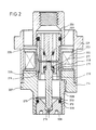
- FIG. 2 shows a further high-pressure injection valve, which is constructed similarly to that according to FIG. 1. Two slightly different versions are shown on the right and left. Various options for fastening the magnetic pole and a particularly favorable design for setting the armature stroke are explained. Only the details deviating from Fig. 1 are discussed here.
- the magnetic circuit of the valve consists of the magnetic pole 204, the housing 201 and the armature 215. Furthermore, the magnetic yoke on the right side of FIG. 2 takes place through the carrier 214, which is screwed to the support sleeve 208. The magnetic pole 204 is screwed directly to the non-magnetizable support sleeve 208. On the left side of FIG. 2, the pole 204 is carried by a non-magnetizable sleeve 206, which is fastened within the lower support sleeve 207 made of magnetizable material. The attachment is preferably carried out by brazing or by laser welding.
- the machining of the end face of the magnetic pole 204 and the guide bore for the armature 215 can be carried out together in one setting, which makes it easy to maintain a precise rectangular position.
- the pole 204 and the armature 215 on the left side of FIG. 2 are each composed of two concentric parts.
- the armature 215 carries the sleeve 216 and the pole 204 carries the sleeve 204.
- the advantage of such an embodiment is reduced eddy current formation, since the individual parts can be made thinner overall.
- the armature stroke is adjusted by rotating the seat support 209.
- the seat support 209 is braced against the valve neck 208 without play.
- the bracing takes place through the spring action of the shoulder 213 above the sealing ring groove 220.
- the bracing seat bracket 209 achieves a high tensioning force with a particularly small size of the valve.
- a fitting ring 211 is arranged between the shoulder 213 and the shoulder of the valve neck 208.
- the fitting ring 211 is used for rough adjustment of the valve stroke.
- the fine calibration is then carried out after a test run of the valve by rotating the seat support 209 accordingly.
- a braceable shoulder can also be arranged on the outer circumference of the seat support, which then rests on the end of the neck 208 Edition reached.
- the necessary elasticity is then also achieved by an undercut groove within the seat support.
- the tensionable seat bracket 209 permits particularly simple and reliable static calibration of the valve. The required long-term stability of the adjustment would not be reliably guaranteed with a separate spring element.
- the tensionable seat support can also be used advantageously for low-pressure injection valves.
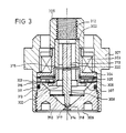
- FIG 3 shows a further high-pressure injection valve, the magnetic circuit of which has a double working air gap.
- the outside diameter of the valve is approx. 20 mm.
- the magnetic circuit of the valve consists of the armature 307, the central pole 302, the housing 301 and the side pole 306.
- the magnetic circuit has two working air gaps 315 and 316.
- the central working air gap 315 is arranged within the solenoid coil 303.
- the outer diameter of the central pole 302 is approximately 6-8 mm.
- the wall thickness of the central pole 302 is approximately 0.8-1.2 mm.
- the area of the two magnetic poles is approx. 15-20 mm2 each.
- armature 307 is tightened, a residual air gap of approximately 0.05 mm remains in the area of working poles 315 and 316.
- the valve stroke is preferably approximately 0.05-0.1 mm.
- the magnet coil 303 is wound on a coil body 304 made of non-magnetizable material.
- the coil body 304 serves to seal the coil space and can consist, for example, of austenitic steel or of high-strength ceramic.
- the coil space can be filled with a sealing compound to seal and improve the mechanical stability.
- the magnetic coil 303 can also be made from a thin film. Such a film spool has a very high mechanical and electrical stability, so that it is then also possible to dispense with a sealing of the coil space from the system pressure.
- the valve needle 308 has a side collar 322 to which the armature 307 is attached. The total moving mass of the armature 307 and the valve needle 308 together is approximately 1 g. The diameter of the valve needle 308 is approximately 2-2.5 mm.
- a ballic pin 317 is worked onto the valve needle 308 and closes the valve seat.
- the diameter of this pin 317 is approximately 0.8 mm.
- the non-pressure-equalized area of the valve seat 318 is approximately 0.3 mm2.
- the design pressure of the valve is approx. 500 bar.
- a stop pin 319 the diameter of which is approximately 0.5-0.8 mm, is machined onto the top of the valve needle 308.
- the stop pin 319 is surrounded by the damping chamber 320.
- the stop pin 319 comes to rest against the central stop 312 when the anchor 307 is tightened.
- the central stop 312 is made of non-magnetizable material and is fastened within the magnetic pole 302, for example by brazing.
- the valve needle 308 is clamped between two diaphragm springs 305 and 310, and is guided through them with little play in the radial direction.
- Diaphragm springs 305 and 310 are provided with openings to allow fuel to pass through.
- the vibration damper 313 is arranged between the armature 307 and the upper diaphragm spring 305.
- the return spring force can be set by selecting a suitable thickness of the vibration damper 313.
- Another vibration damper can be arranged between the lower diaphragm spring 310 and the valve needle 308.
- the coil former 304, the diaphragm spring 305 and the side pole 306 are clamped within the housing 301 by the seat support 309.
- the seat support 309 is designed to be elastic in the area of the sealing ring groove 311, so that the valve lift can be calibrated by screwing the seat support 309 in correspondingly deeply.
- the fuel supply to the valve seat 318 takes place through the central connecting piece 325 on the housing 301, through lateral grooves in the central stop 312 and in the collar 322 of the valve needle 308, and further through the openings in the diaphragm springs 305 and 310.
- the advantage of the above valve design compared to the valve designs according to FIG. 1 and FIG. 2 is less eddy current formation, since the magnetic circuit can be made thinner-walled at a predetermined maximum magnetic force.
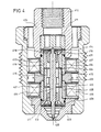
- FIG. 4 shows a high-pressure injection valve with a polarized magnetic circuit.
- the basic structure of the polarized magnetic circuit is known.
- the design pressure of the valve is approx. 1000 bar.
- the outside diameter of the valve is approx. 22 mm.
- the valve allows the fastest positioning movements.
- the disadvantage is a considerably increased construction effort.
- a monostable version is understood to mean a valve which automatically goes into the closed position after the excitation current has been switched off.
- the monostable version offers the advantage of increased safety in the event of malfunctions in the electrical control circuit.
- an electrical counter pulse is required to close the valve.
- the bistable design offers the advantage of better efficiency and thus a higher working speed.
- the valve shown has a friction-free armature suspension between two diaphragm springs with a very steep spring characteristic. The spring force is zero when the valve is in the half-open position.
- the maximum spring force is reached in the respective end positions of the valve both in the open and in the closed position.
- the spring force in the closed position of the valve should correspond approximately to the sum of the permanent magnetic force of the magnetic circuit and the closing force required for safety reasons.
- injection valves with polarized magnetic circuits can achieve much faster actuating movements than with the usual flat spring characteristic curves.
- Flat spring characteristics would result when using coil springs.
- the valve is suitable for a fuel pressure of up to approx. 1000 bar.
- the polarized solenoid valve according to FIG. 4 has a tubular armature 415 which is firmly connected to the valve needle 416.
- the outer diameter of the armature 415 is preferably 7-8 mm.
- the wall thickness of the anchor is preferably approximately 0.8-1.2 mm.
- the total mass of armature 415 and valve needle 416 is approximately 1.5 g.
- the valve needle 416 is suspended on the top and bottom in the diaphragm springs 413 and 414.
- the characteristic curve of the diaphragm springs 413 and 414 is calibrated by grinding the flat side of these springs accordingly.
- the vibration absorbers 417 and 418 are arranged between the diaphragm springs 413 and 414 and the valve needle 416.
- the diaphragm springs 413 and 414 are provided with openings which allow fuel to pass through.
- the armature stroke is limited by the upper stop 411, against which the valve needle 416 comes to a stop when the valve is open.
- the two magnetic poles of the valve are arranged within non-magnetizable sleeves.
- the bistable valve on the right side of Fig. 4 has a magnetically symmetrical structure.
- air gaps 423 and 424 are only arranged between the armature 415 and the two magnetic poles 409 and 410.
- the non-magnetizable sleeve 420 forms an additional air gap between the upper magnetic pole 419 and the sealing plug 426. This additional air gap weakens the magnetic field within the upper working air gap 424. This ensures that the armature 415 automatically returns to the rest position by the stronger magnetic field in the region of the lower working air gap 423.
- residual air gaps 423 and 424 of preferably approximately 0.05 mm each.
- the residual air gaps are required to avoid hydraulic sticking.
- a desired hydraulic damping of the actuating movements is achieved in the area of the residual air gaps.
- a monostable mode of operation can also be achieved through an asymmetrical arrangement of the residual air gaps 423 and 424.
- the upper residual air gap 424 is made considerably longer than the lower residual air gap 423, so that a correspondingly stronger permanent magnetic field is formed in the area of the lower residual air gap 423, which causes the independent resetting.
- the monostable arrangement shown on the left-hand side of FIG. 4 with an additional magnetic air gap between pole 419 and sealing plug 426 is more favorable in terms of magnet technology.
- the permanent magnetic field is generated by the permanent magnet 402, which can be made up of several separate segments.
- the inner magnetic yoke to the armature 415 takes place through the central pole 403.
- the outer magnetic yoke to the two magnetic poles 409 and 410 takes place through the valve housing 401, the upper sealing plug 412 and the seat support 408.
- the central pole 403 is with the non-magnetizable sleeves 404 and 405 or 420 firmly connected.
- the connection is preferably made by laser welding or by brazing.
- the electrical excitation takes place through the two solenoid coils 406 and 407.
- the inner parts of the valve are clamped together with the upper sealing plug 412 in the valve housing 401.
- the interior of the valve is acted on by the full system pressure.
- the installation spaces of the solenoids 406 and 407 are sealed against the system pressure.
- valve according to the invention can also be equipped with a simple nozzle shape other than that shown.
- Such other nozzle shapes are known from the usual mechanical injection nozzles. These known nozzle shapes can be used in miniaturized form without further ado in the valve according to the invention.
- the valve can be equipped with a miniaturized pin nozzle to improve atomization, in which case the pin diameter should be approximately 0.5-0.7 mm.
- the atomization can also be improved by using very short nozzles with a length of less than 0.5 mm.
- the mouth of such a nozzle can be sunk to improve the mechanical strength.
- the use of such short nozzles is made possible in the valve according to the invention because of the low mechanical load in the seat area.
- the nozzle on the combustion chamber side can be provided with a radius with a radius of a few 1/100 mm or with a conical outlet, which also improves atomization and achieves a larger spray cone.
- Vertebral bodies for generating a fuel swirl can be arranged within the injection nozzle or on the valve needle.
- a blind hole can be arranged below the valve seat, which supplies one or more obliquely arranged nozzles with fuel. This makes it possible to change the beam direction.
- the flow quality in the inflow region of the nozzle is considerably impaired by the blind hole, which overall always results in a considerable deterioration in the dynamic properties of the valve. Blind holes below the valve seat should therefore be avoided if possible in the valve according to the invention.
- the valve according to the invention could theoretically also be equipped with a collar-shaped stop which partially encompasses the valve needle.
- the collar-shaped stop can have a single or several radially evenly distributed separate stop areas.
- the stop surface of such a stop would only have to be made sufficiently small.
- Such a stop shape is generally known from the field of low-pressure injection valves.
- With a collar-shaped stop however, there are extremely great difficulties in maintaining an exact parallelism of the stop surfaces. It is hardly possible to maintain the required parallelism even with very precise machining methods.
- such a high-pressure injection valve with a collar-shaped stop will often result in strongly fluctuating hydraulic adhesive forces which result in impermissible, strongly fluctuating closing times of the valve. Such an embodiment causes a high manufacturing scrap. Therefore, the high-pressure injector according to the invention will always prefer the design proposed here with a single central stop.
Abstract
Description
Die Erfindung betrifft elektromagnetisches Hochdrukeinspritzventil zur Einspritzung von Kraftstoff in den Brennraum von Verbrennungsmotoren. Das Einspritzventil soll hauptsächlich bei kleinen und mittleren Dieselmotoren mit einem Hubraum von 300 cm³ bis 700 cm³ pro Zylinder zur Anwendung kommen. Die typische Durchflußrate des Ventils beträgt 10-25 mm³/ms. Das Einspritzventil ist bis zu einem Kraftstoffdruck von ca. 1000 bar einsetzbar. Das Ventil besitzt einen nadelförmigen Ventilschließkörper, der mit dem Anker eines Elektromagneten verbunden ist. Ähnlich wie bei den bekannten Niederdruckeinspritzventilen wird der Kraftstoffzulauf zur Einspritzdüse beim Anzug des Ankers freigegeben. Das Einspritzventil wird durch eine vom Motor mechanisch angetriebene Hochdruckkolbenpumpe mit Kraftstoff versorgt.The invention relates to an electromagnetic high-pressure injection valve for injecting fuel into the combustion chamber of internal combustion engines. The injection valve is mainly used for small and medium-sized diesel engines with a displacement of 300 cm³ to 700 cm³ per cylinder. The typical flow rate of the valve is 10-25 mm³ / ms. The injection valve can be used up to a fuel pressure of approx. 1000 bar. The valve has a needle-shaped valve closing body which is connected to the armature of an electromagnet. Similar to the known low-pressure injection valves, the fuel supply to the injection nozzle is released when the armature is pulled up. The injection valve is supplied with fuel by a high-pressure piston pump mechanically driven by the engine.
Bei Dieselmotoren werden sehr hohe Einspritzdrücke von bis zu über 1000 bar angestrebt, um die Kraftstoffaufbereitung zu verbessern und die Schadstoffbildung zu veringern. Im allgemeinen wird ein steiler Einspritzverlauf zu Beginn der Einspritzung und ein scharf begrenztes Einspritzende gefordert. Beginn und Zeitdauer der Einspritzung müssen an die Bedingungen der Motorkennfeldes angepaßt werden.In diesel engines, very high injection pressures of up to over 1000 bar are aimed for in order to improve fuel processing and reduce pollutant formation. In general, a steep injection course at the beginning of the injection and a sharply limited injection end are required. The start and duration of the injection must be adapted to the conditions of the engine map.
Zur Hochdruckeinspritzung werden üblicherweise rein mechanisch arbeitende Einspritzsysteme eingesetzt. Hierbei wird der Kraftstoff zu Beginn des Einspritzvorganges in einem Pumpenelement verdichtet und die Pumpenenergie als Druckwelle zur Einspritzdüse übertragen. die Einspritzdüse ist mit einer Düsennadel versehen, die durch den Kraftstoffdruck gegen die Kraft einer Feder vom Ventilsitz abgehoben wird. Bei kleinen Einspritzdüsen für Fahrzeugmotoren beträgt die Masse der Düsennadel ca. 5-10 g. Die Rückstellkraft der Feder beträgt je nach Öffnungsdruck der Düse zwischen 400 und 2000 N. Der Stitzdurchmesser der Einspritzventile beträgt in der Regel ca. 2 mm. Durch die hohe Rückstellkraft und die relativ große Masse der Düsennadel ist der Ventilsitz beim Schließen des Ventils einer starken Schlagbelastung ausgesetzt.Purely mechanical injection systems are usually used for high-pressure injection. Here, the fuel is compressed in a pump element at the start of the injection process and the pump energy is transmitted to the injection nozzle as a pressure wave. the injection nozzle is provided with a nozzle needle which is lifted off the valve seat by the fuel pressure against the force of a spring. With small injection nozzles for vehicle engines, the mass of the nozzle needle is approx. 5-10 g. The resetting force of the spring is between 400 and 2000 N depending on the opening pressure of the nozzle. The diameter of the injectors is usually approx. 2 mm. Due to the high restoring force and the relatively large mass of the nozzle needle, the valve seat is exposed to a strong impact when the valve is closed.
Während und nach dem Einspritzvorgang werden zwischen Pumpe und Düse starke Druckwellen reflektiert. Die Amplitude dieser Wellen kann bis zu mehreren 100 bar betragen. Bei den Druckwellen können nach Schließen der Einspritzdüse Berührungen der Nullinie auftreten, bei denen der Dampfdruck des Kraftstoffs unterschritten wird. Dies führt zu Kavitation an den Elementen der Einspritzanlage und zu Hohlraumbildung mit starken stoßartigen Belastungen. Weiterhin können die reflektierten Druckwellen einen erneuten Öffnungsvorgang der Nadel auslösen. Hierbei tritt ein um die Laufzeit der Druckwelle verzögertes Nachspritzen auf, bei dem der Kraftstoff nur noch mangelhaft zerstäubt wird und nur unvollständig an der Verbrennung teilnimmt. Ein zusätzliches Nachspritzen entsteht durch das stets vorhandene Nadelprellen beim schließen des Ventils.Strong pressure waves are reflected between the pump and nozzle during and after the injection process. The amplitude of these waves can be up to several 100 bar. After closing the injector, the pressure waves may touch the zero line, below which the vapor pressure of the fuel falls below. This leads to cavitation in the elements of the injection system and to the formation of cavities with strong shock loads. Furthermore, the reflected pressure waves can trigger the needle to open again. In this case, post-spraying is delayed by the duration of the pressure wave, in which the fuel is atomized only poorly and only partially participates in the combustion. Additional injection is created by the needle bouncing that is always present when the valve is closed.
Der Pumpvorgang ist bei den mechanisch arbeitenden Einspritzsystemen an einen bestimmten Drehwinkel fest gekoppelt. Es ergibt sich eine hohe stoßartige mechanische Belastung der Einspritzpumpe, da der gesamte Druckaufbau innerhalb des geringen Drehwinkels in sehr kurzer Zeit stattfindet. Da die Zeit zum Durchlaufen dieses Winkels mit zunehmender Motordrehzahl immer kürzer wird, andererseits jedoch der Querschnitt der Düsenlöcher konstant bleibt, ergibt sich ein starker drehzahlabhängiger Druckanstieg, welcher zu erhebliche Problemen bei der Kraftstoffaufbereitung führt. Bei niedrigen Drehzahlen reicht der Druck meist nicht aus, um die Düsennadel vollständig anzuheben.The pumping process in the mechanically operating injection systems is firmly coupled to a certain angle of rotation. The injection pump is subjected to a high shock-like mechanical load, since the entire pressure build-up takes place within a very short time within the small angle of rotation. Since the time to go through this angle becomes shorter and shorter with increasing engine speed, but on the other hand the cross-section of the nozzle holes remains constant, there is a strong speed-dependent pressure rise, which leads to considerable problems in fuel preparation. At low speeds, the pressure is usually not sufficient to raise the nozzle needle completely.
Bei teilweise geöffneter Nadel wird der überwiegende Teil des Kraftstoffdrucks im Ventilsitz in Geschwindigkeit umgesetzt und anschließen im Sackloch der Düse verwirbelt. Zur Geschwindigkeitsumsetzung steht dann nur noch ein geringer Kraftstoffdruck vor den Düsenlöchern zur Verfügung, so daß sich eine sehr mangelhafte Zerstäubung ergibt.When the needle is partially open, the major part of the fuel pressure in the valve seat is converted into speed and then swirled in the blind hole of the nozzle. Then only a low fuel pressure is available in front of the nozzle holes for speed conversion, so that there is a very poor atomization.
Der drehzahlabhängige Druckanstieg erschwert die Abstimmung der Einspritzdüse auf die Erfordernisse des Motors, so daß bei den mechanisch arbeitenden Einspritzsystemen nur in eng begrenzten Drehzahl- und Lastbereichen optimale Verhältnisse erzielt werden.The speed-dependent pressure increase makes it difficult to match the injection nozzle to the requirements of the engine, so that the mechanically operating injection systems can only achieve optimal conditions in narrowly limited speed and load ranges.
Es ist naheliegend, Einspritzventile mit elektromagnetischer Betätigung einzusetzen, um die aus dem Druckwellentransport der Kraftstoffs resultierenden Probleme zu umgehen. Bei elektromagnetischen Einspritzventilen ist eine schnelle und prellarme Stellbewegung erforderlich, um eine ausreichende Zumeßgenauigkeit zu erzielen. Diese kann nur mit einem Anker von sehr geringer Masse mit hoher mechanischer Steifigkeit erzielt werden. Die Anzugs- und Abfallzeit sollte weniger als 0.5 ms betragen. Die erforderliche kurze Anzugszeit soll mit möglichst geringer elektrischer Leistung erzielt werden. Die Anpassung der elektromagnetischen Einspritzventile an die Bedingungen der Motorkennfeldes ist mit bekannten elektronischen Steuerungen einfach realisierbar.It is obvious to use injectors with electromagnetic actuation in order to avoid the problems resulting from the pressure wave transport of the fuel. With electromagnetic injection valves, a quick and low-bounce actuating movement is required in order to achieve sufficient metering accuracy. This can only be achieved with an anchor of very low mass with high mechanical rigidity. The pull-in and drop-out time should be less than 0.5 ms. The required short tightening time should be achieved with the lowest possible electrical power. The adaptation of the electromagnetic injection valves to the conditions of the engine map can be easily implemented using known electronic controls.
Die bekannten elektromagnetischen Einspritzventile zur Einspritzung von Kraftstoff in den Brennraum von Verbrennungsmotoren erfordern eine große Magnetkraft, welche zur Überwindung der an der Ventilnadel angreifenden hydraulischen Kräfte erforderlich ist. Es bestehen enorme Schwierigkeiten, ausreichend schnelle Elektromagnete zu bauen, die die hohen hydraulischen Kräfte mit tragbarem Energieaufwand überwinden können. Die bekannten elektromagnetischen Einspritzventile mit direktbetätigter Ventilnadel besitzen einen sehr starken Elektromagneten, der häufig mehrere gleichzeitig erregte Magnetspulen aufweist. Um mit einem solchen Elektromagnet ausreichend schnelle Stellbewegungen zu erzielen, muß kurzfristig eine enorme elektrische Leistung zur Verfügung gestellt werden. Weiterhin werden die Anker derartiger Elektromagnete möglichst dünnwandig ausgeführt, um eine geringe Ankermasse zu erzielen, und um die Wirbelstrombildung im Magneteisen zu verringern. Wegen der dünnwandigen Ausführung neigen die Anker bei schnellen Stellbewegungen zu starken mechanischen Schwingungen, durch die unerwünschte Prellbewegungen und Störkräfte ausgelöst werden.The known electromagnetic injection valves for injecting fuel into the combustion chamber of internal combustion engines require a large magnetic force, which is necessary to overcome the hydraulic forces acting on the valve needle. There are enormous difficulties in building sufficiently fast electromagnets that can overcome the high hydraulic forces with a portable energy expenditure. The known electromagnetic injection valves with a directly actuated valve needle have a very strong electromagnet, which often has several magnet coils excited at the same time. In order to achieve sufficiently rapid actuating movements with such an electromagnet, enormous electrical power must be made available at short notice. Furthermore, the armatures of such electromagnets are made as thin-walled as possible in order to achieve a low armature mass and to reduce the eddy current formation in the magnet iron. Because of the thin-walled design, the anchors tend to generate strong mechanical vibrations during rapid positioning movements, which can trigger undesired bouncing movements and disruptive forces.
Ein bekanntes Einspritzventil (DE-A 23 43 243), das für Zweitaktmotoren vorgesehen ist, weist keine Begrenzung für den Einspritzhub der Nadel auf. Dies macht eine sehr präzise Steuerung des Anlaufhubs erforderlich, die mit manuellen Mitteln eingestellt werden soll.A known injection valve (DE-A 23 43 243), which is intended for two-stroke engines, has no limit for the injection stroke of the needle. This requires a very precise control of the starting stroke, which should be set by manual means.
Ziel der Erfindung ist ein elektromagnetisches Hochdruckeinspritzventil, das bei geringer Erregerleistung ausreichend schnelle und prellarme Stellbewegungen erlaubt. Das Einspritzventil soll im Vergleich zu den bekannten Ausführungen dieser Gattung eine relativ einfache Fertigung erlauben.The aim of the invention is an electromagnetic high-pressure injection valve which allows sufficiently rapid and low-bounce actuating movements with a low excitation power. The injection valve should allow a relatively simple manufacture compared to the known designs of this type.
Bei Untersuchungen des Anmelders hat sich überraschenderweise gezeigt, daß die erforderliche Öffnungsarbeit und das erforderliche Magnetkraftniveau bei gegebenem Ventilhub und gegebenem Durchfluß nahezu unabhängig vom Einspritzdruck ist. Daher ist bei einem kleinen erforderlichen Durchfluß auch bei sehr hohem Einspritzdruck nur eine geringe Öffnungsarbeit erforderlich, die bereits von einem sehr kleinen Anker mit sehr geringer Masse aufgebracht werden kann. Hierzu ist jedoch ein außergewöhnlich geringer Durchmesser des Ventilsitzes erforderlich. Der Durchmesser des Ventilsitzes beträgt bei dem erfindungsgemäßen Einspritzventil vozugsweise 0.5-0.8 mm. Bereits bei einem derartig kleinen Sitzdurchmesser kann die erforderliche Durchflußrate zum Betrieb von kleinen Dieselmotoren mit einem geringem Hub von 0.05-0.15 mm erzielt werden.Surveys by the applicant have surprisingly shown that the required opening work and the required magnetic force level for a given valve stroke and given flow is almost independent of the injection pressure. Therefore, with a small flow required, even with a very high injection pressure, only a small opening work is required, which can be applied by a very small anchor with a very low mass. However, this requires an exceptionally small diameter of the valve seat. The diameter of the valve seat is preferably 0.5-0.8 mm in the injection valve according to the invention. Even with such a small seat diameter, the flow rate required to operate small diesel engines with a small stroke of 0.05-0.15 mm can be achieved.
Bei der erfindungsgemäßen Dimensionierung des Einspritzventils ist die erforderliche maximale Öffnungkraft bei gegebenem Hub lediglich vom verlangten Durchfluß abhängig. Der Hub des Ventils sollte ca. 0.05-0.15 mm betragen. Das Einspritzventil wird durch entsprechende Verringerung des äußeren Durchmessers des Ventilsitzes bis herab zu 0.4 mm an hohe Kraftstoffdrücke angepaßt. Die maximale Öffnungskraft ergibt sich aus dem Produkt aus Kraftstoffdruck und der nicht druckausgeglichenen Fläche des Ventilsitzes. Die nicht druckausgeglichenen Fläche des Ventilsitzes beträgt stets weniger als 1 mm².In the dimensioning of the injection valve according to the invention, the required maximum opening force for a given stroke is only dependent on the required flow. The stroke of the valve should be approx. 0.05-0.15 mm. The injection valve is adapted to high fuel pressures by reducing the outer diameter of the valve seat down to 0.4 mm. The maximum opening force results from the product of the fuel pressure and the non-pressure-equalized area of the valve seat. The area of the valve seat that is not pressure-balanced is always less than 1 mm².
Bei den üblichen Hochdruckeinspritzventilen ist ein zuverlässiger Betrieb bei einem derartig geringen Sitzdurchmesser von vozugsweise 0.5-0.8 mm nicht möglich. Der Ventilsitz würde bei einem derartig geringen Durchmesser wegen der hohen Schlagbelastung schnell zerstört werden. Der Fachmann wird daher zunächst vermuten, daß wegen des geringen Sitzdurchmessers des erfindungsgemäßen Ventils ein zuverlässiger Betrieb wegen untragbaren Verschleißes im Sitzbereich nicht möglich sein wird. Aufgrund des geringen Durchmessers des Ventilsitzes beträgt jedoch die maximale unausgeglichene hydraulische Schließkraft nur ca. 5-20 N. Diese geringe hydraulische Gegenkraft kann bereits mit einem sehr kleinen Elektromagneten überwunden werden. Der Zuverlässige Betrieb des erfindungsgemäßen Einspritzventils wird durch ein gegenüber der üblichen Hochdruckeinspritzventilen drastisch verringertes Kraftniveau und eine besonders geringe Ankermasse von vorzugsweise ca. 1-2 g ermöglicht. Durch das geringe Kraftniveau und die geringe Ankermasse wird die auftretende Schlagbelastung im Sitzbereich innerhalb zulässiger Grenzen gehalten.With conventional high-pressure injection valves, reliable operation with such a small seat diameter of preferably 0.5-0.8 mm is not possible. With such a small diameter, the valve seat would be quickly destroyed due to the high impact load. The person skilled in the art will therefore first assume that, because of the small seat diameter of the valve according to the invention, reliable operation will not be possible due to intolerable wear in the seat area. However, due to the small diameter of the valve seat, the maximum unbalanced hydraulic closing force is only approx. 5-20 N. This low hydraulic counterforce can be overcome with a very small electromagnet. Reliable operation of the injection valve according to the invention is made possible by a force level which is drastically reduced compared to the conventional high-pressure injection valves and a particularly low armature mass of preferably approximately 1-2 g. Due to the low level of force and the low anchor mass, the impact load occurring in the seating area is kept within permissible limits.
Weiterhin ist der Anker des Einspritzventils vollständig von unter Druck stehendem Kraftstoff umspült. Der Ankerraum ist im Gegensatz zu den meisten bisher vorgeschlagenen Konstruktionen nicht durch eine enge Nadelführung vom Systemdruck getrennt. Die vollständige Umspülung des Ankers mit unter Druck stehendem Kraftstoff ist bei dem erfindungsgemäßen Einspritzventil unbedingt erforderlich, um die Entstehung von unausgeglichenen Störkräften weitgehend zu verhindern.Furthermore, the armature of the injection valve is completely surrounded by fuel under pressure. In contrast to most of the previously proposed designs, the anchor space is not separated from the system pressure by a narrow needle guide. Complete flushing of the armature with fuel under pressure is absolutely necessary in the injection valve according to the invention in order to largely prevent the occurrence of unbalanced interference forces.
Weitere erforderliche und zweckmäßige Maßnahmen, die den zuverlässigen Betrieb des Einspritzventils trotz der geringen Magnetkraft erlauben, werden anhand der Ausführungsbeispiele nachfolgend erläutert:Further necessary and expedient measures that allow reliable operation of the injection valve despite the low magnetic force are explained below using the exemplary embodiments:
Fig.1 zeigt ein erfindungsgemäßes Hochdruckeinspritzventil, dessen Außendurchmesser lediglich ca. 20 mm beträgt. Der Auslegungsdruck des Ventils beträgt ca. 200-300 bar. Der Ankerhub des Ventils beträgt 0.05-0.1 mm, der Außendurchmesser des Ventilsitzes beträgt 0.8 mm. Der Magnetkreis des Ventils besteht aus dem Anker 112, dem Magnetpol 108, dem Gehäuse 101 und dem Träger 116. Sämtliche Teile des Magnetkreises bestehen aus weichmagnetischem Material. Die Erregung des Magnetkreises erfolgt durch die Magnetspule 105, die auf den Spulenkörper 106 aufgewickelt ist. Die Magnetspule 105 besitzt vorzugweise ca. 100 Windungen. Der Magnetpol 108 und der Anker 112 sollten aus einem Material mit hoher Sättigungsinduktion bestehen, um eine möglichst hohe Magnetkraft zu erzielen. Als Material ist ein Eisenwerkstoff mit bis zu 50% Cobaltanteil gut geeignet. Der Außendurchmesser des Ankers 112 beträgt vorzugsweise ca. 7-8 mm, die Wandstärke beträgt vorzugsweise ca. 1-1.2 mm. Die maximal Magnetkraft des Elektromagneten beträgt bei Sättigung des Magneteisens ca. 25-40 N.1 shows a high-pressure injection valve according to the invention, the outer diameter of which is only approximately 20 mm. The design pressure of the valve is approx. 200-300 bar. The armature stroke of the valve is 0.05-0.1 mm, the outside diameter of the valve seat is 0.8 mm. The magnetic circuit of the valve consists of the
Der rohrförmige Anker 112 ist auf die Ventilnadel 113 aufgepreßt, die mit dem zentralen Anschlagstift 125 unmittelbar auf dem Anschlagelement 126 zum Anschlag gelangt. Der Anker 112 ist durch eine zusätzliche Laserschweißung oder durch Verlöten mit der Ventilnadel 113 gegen axial Verlagerung gesichert. Die Rückstellung des Ankers erfolgt durch die Rückstellfeder 110, welche innerhalb des Ankers 112 und des Magnetpols 108 angeordnet ist.The
Die Anschlagfläche des Anschlagstiftes 125 überragt die Stirnfläche des Ankers 112 um ca. 50 Mikrometer, so daß auch bei angezogenem Anker ein Restluftspalt zwischen Pol und Anker verbleibt. Durch den Restluftspalt wird ein rascher Abbau des Magnetfeldes nach dem Abschalten des Erregerstroms erzielt. Weiterhin wird durch den Restluftspalt eine unzulässig starke Dämpfung der Anzugsbewegung des Ankers vermieden.The stop surface of the
Am unteren Ende der Ventilnadel ist ein nadelförmiger Schließkörper 119 angearbeitet, der den Ventilsitz 120 verschließt. Der Durchmesser des nadelförmigen Schließkörpers 119 beträgt ca. 2 mm. Der kegelförmige Ventilsitz 120 und die Düse 118 ist unmittelbar in den Düsenträger 117 eingearbeitet. Die Düse 118 ist ohne Zwischenschaltung des sonst üblichen Sackloches unmittelbar unterhalb des Ventilsitzes 120 angeordnet. Hierdurch wird eine sehr gute Strömungqualität mit einer wirbelarmen Umsetzung des Kraftstoffdruckes erzielt.At the lower end of the valve needle, a needle-shaped
Das Einspritzventil besitzt eine hydraulische Kennlinienanpassung, bei der die hydraulischen Rückstellkräfte bei angezogenem Anker diejenigen bei abgefallenem Anker übersteigen. Mit einer derartigen Kennlinienanpassung wird die Rückstellzeit des Ankers erheblich verkürzt. Hierzu ist das untere Ende der Ventilnadel 113 mit geringem Radialspiel von einigen 1/100 mm innerhalb der Führungsbohrung 112 geführt. Der Durchmesser der Führungsbohrung 112 beträgt ca. 2 mm. Innerehalb des Ringspaltes zwischen der Ventilnadel 113 und der Führungsbohrung 112 entsteht ein Druckabfall, der mit zunehmendem Durchfluß und damit mit zunehmendem Ankerhub zunimmt. Durch diesen Druckabfall wird eine mit zunehmendem Ankerhub zunehmende hydraulische Kraft erzeugt, die der Magnetkraft entgegengerichtet ist. Das Radialspiel des Ventilnadel innerhalb der Führungsbohrung wird so bemessen, daß bei angezogenem Anker hinter dem Ringspalt ein bleibender Druckabfall von ca. 10-20% des statischen Kraftstoffdruckes entsteht. Der Durchmesser des Ringspaltes sollte etwa 2-3 fach größer als derjenige des Ventilsitzes 111 gewählt werden. Bei des angegebenen Dimensionierung wird eine hydraulische Zentrierung des Schließkörpers und eine Dämpfung der Aufschlagbewegung des Schließkörpers auf den Ventilsitz erzielt, ohne daß hierdurch die Rückstellzeit des Ankers unzulässig verlängert würde. Durch die Dämpfung der Rückstellbewegung wird das Schließprellen stark vermindert. Innerhalb der Ventilnadel 113 ist eine Nut 121 angeordnet. Die Nut 121 dient zur Vergrößerung des bleibenden Druckabfalls und zur gleichmäßigen Verteilung des Druckabfalls über den Umfang des Ringspaltes.The injection valve has a hydraulic characteristic curve adjustment, in which the hydraulic restoring forces when the armature is tightened exceed those when the armature has dropped. With such a characteristic curve adjustment, the reset time of the armature is considerably shortened. For this purpose, the lower end of the
Der Magnetpol 108 wird von einer nichtmagnetisierbaren Hülse 107 getragen, die am unteren Ende einen Kragen 129 besitzt. Die Hülse 107 ist mit dem Kragen 129 zwischen dem mittleren Gehäuseteil 116 und dem Düsenträger 117 eingeklemmt. Das Ventilgehäuse 101 ist mit dem mittleren Gehäuseteil 116 verschraubt. Die Befestigung des Magnetpols 108 innerhalb der Hülse 107 erfolgt vorzugsweise durch Einpressen und anschließende Laserschweißung oder durch Hartlöten. Die Hülse 107 sollte aus austenitischem Stahl mit möglichst hohem elektrischen Widerstand bestehen, um die Wirbelstrombildung innerhalb der Hülse gering zu halten. Innerhalb des Magnetpols 108 ist ein Anschlagelement 126 eingepreßt, das aus nicht magnetisierbarem Material besteht. Das Anschlagelement 126 ist mit dem Magnetpol 108 fest verbunden und mit seitlichen Nuten 130 versehen, die einen Kraftstoffdurchtritt erlauben. Die Stirnfläche des Anschlagelementes 126 und diejenige des Magnetpols 108 befinden sich in einer gemeinsamen Ebene.The
Der Kraftstoff gelangt durch eine nicht dargestellte Versorgungsleitung in das Ventilgehäuse. Die Versorgungsleitung wird mit dem oberen Gehäuseteil 101 verschraubt. Von hier gelangt der Kraftstoff durch seitliche Nuten im oberen Anschlag 126 und durch seitliche Nuten 123 in der Ventilnadel 113 zum Ventilsitz 120. Der Magnetpol 118 ist durch den Dichtring 109 gegen das Gehäuse 101 abgedichtet.The fuel reaches the valve housing through a supply line, not shown. The supply line is screwed to the
Zu Beginn der Ankerrückstellung entsteht eine hydraulische Klebekraft durch Vakuumbildung zwischen dem Anschlagstift 125 und dem Anschlagelement 126. Die hydraulische Klebekraft ist der Kraft der Rückstellfeder 110 engegengerichtet und bewirkt eine unerwünschte Verzögerung der Ankerrückstellung. Bei einer zu großen Anschlagfläche kann es sogar zu einer Blockierung und damit zur Funktionsuntüchtigkeit des Ventils kommen. Daher ist es unbedingt erforderlich, die hydraulische Klebekraft so gering wie möglich zu halten. Die Größe der Berührungsfläche zwischen dem Anschlagstift 125 und dem Anschlagelement 126 sollte diejenige des Ventilsitzes keinesfalls überschreiten. Der Durchmesser des Anschlagstiftes 125 sollte daher geringer als derjenige des Ventilsitzes sein. Der Durchmesser des Anschlagstiftes 125 beträgt vorzugsweise 0.5-1 mm. Weiterhin muß eine direkte Berührung zwischen Magnetpol 108 und Anker 112 unbedingt vermieden werden, um eine hydraulische Blockierung des Ankers zu verhindern.At the beginning of the armature return, a hydraulic adhesive force arises from the vacuum formation between the
Aufgrund der sehr geringen Anschlagfläche zwischen dem Anschlagstift 125 und dem Anschlagelement 126 kommt es beim Aufschlag des Ankers zu einer hohen Schlagbelastung. Diese hohe Schlagbelastung muß durch Dämpfung der Anzugsbewegung des Ankers auf zulässige Werte begrenzt werden. Hierzu ist an der Stirnseite der Ventilnadel 113 eine Dämpfungskammer eingearbeitet, die durch die umlaufende Tasche 128 gebildet wird. Die Dämpfungskammer ist von einem schmalen Kragen 124 umgeben. Die Stirnfläche des umlaufenden Kragens 124 ist gegenüber der Stirnfläche des Anschlagstiftes 125 um ca. 5-10 Mikrometer zurückversetzt. Hierdurch verbleibt auch bei angezogenem Anker eine enger Quetschspalt, durch den der Kraftstoff während des Ankeranzugs herausgepreßt wird. Durch die Quetschströmung wird eine Dämpfung der Aufschlagbewegung erzielt. Eine zusätzliche Dämpfung erfolgt durch die Quetschströmung im Bereich des Restluftspaltes 127. Durch die zuvor beschriebenen Maßnahmen wird eine gute Dämpfung der Aufschlagbewegung des Ankers bei minimalem hydraulischem Kleben erzielt. Ohne Dämpfungsmaßnahmen wäre ein stabiler und verschleißarmer Betrieb des Einspritzventils bei der sehr geringen Fläche des Anschlagstiftes 125 nicht möglich. Zur Fertigung der Dämpfungskammer und der Anschlagstiftes 125 wird zweckmäßigerweise zunächst die Polfläche 127 des Ankers 112 gemeinsam mit der Stirnfläche der Ventilnadel 131 plan geschliffen. Anschließend wird die zurückverlegte Dämpfungskammer 128 und der Restluftspalt durch Einprägen oder durch Elektroerodieren der Stirnfläche gefertigt.Due to the very small stop surface between the
Bei einem sehr geringen Durchmesser des Anschlagstiftes 125 wird eine Selbststabilisierung des Ventils durch Verschleiß erzielt. Bei einem Verschleiß im Bereich der Anschlagfläche vermindert sich der freie Strömungsquerschnitt zwischen dem Kragen 124 und dem Anschlagelement 126. Hierdurch entstehen stark anwachsende Dämpfungskräfte, die die Schlagbelastung beim Anzug des Ankers stark vermindern. Wegen der mit zunehmendem Verschleiß abnehmenden Schlagbelastung kann bereits nach einer kurzen Einlaufphase ein Stillstand des Verschleißes erzielt werden. Durch den Verschleiß vergrößert sich jedoch der Ventilhub und damit der Durchfluß des Ventils. Bei entsprechend eng tolerierten Teilen ist diese Hubveränderung jedoch auf wenige Mikrometer begrenzt. Derartig geringe Hubveränderungen sind bei dem erfindungsgemäßen Einspritzventil noch tragbar.With a very small diameter of the
Zwischen der Rückstellfeder 110 und der Ventilnadel 113 ist ein Schwingungstilger 111 angeordnet, welcher zur Verminderung der Prellschwingungen dient. Der Schwingungstilger 111 wird von der Stiftförmigen Verlängerung 131 mit geringem Radialspiel axial beweglich geführt. In der Ruhelage wird der Schwingungstilger 111 durch die Kraft der Rückstellfeder 110 fest auf die Schulter der Ventilnadel 113 gepreßt. Nach dem Ankeraufschlag löst sich der Schwingungstilger 111 durch die innewohnende kinetische Energie von der Schulter der Ventilnadel wodurch im Auflagebereich ein enger Spalt entsteht. Hierbei wird zunächst die Ventilnadel 113 von der Kraft der Rückstellfeder entlastet. Weiterhin entsteht die eine sehr starke hydraulische Kraft in Richtung der Öffnungsbewegung, die durch Vakuumbildung innerhalb des entstehenden Spaltes ausgelöst wird. Diese Kraft wirkt den Prellschwingungen entgegen, wodurch diese in kürzester Zeit zum Stillstand kommen. Durch den Schwingungstilger 111 werden auch bei sehr kurzen Öffnungszeiten außerordentlich prellarme, stabile Bewegungsverhältnisse erzielt. Die Masse des Schwingungstilgers ist bei dem erfindungsgemäßen Hochdruckeinspritzventil in weiten Grenzen unkritisch. Die dynamisch günstigsten Verhältnisse werden bei einer Masse des Schwingungstilgers von ca. 10% der Masse von Anker und Ventilnadel erzielt.A
Unterhalb des Ankers ist ein weiterer Schwingungstilger 114 angeordnet, der zur weiteren Dämpfung der Prellschwingungen beim Schließen des Ventils dient. Der Schwingungstilger 114 wird durch eine schwache Feder 115 gegen die untere Schulter der Ventilnadel gedrückt. Die Kraft der Feder 115 ist erheblich geringer als diejenige der Rückstellfeder 110. Die Dämpfung des Schließprellens erfolgt in gleichartiger Weise wie bei dem oberen Schwingungstilger. Die Dämpfung des Schließprellens erfolgt durch Vakuumbildung und Federkraftentlastung in Bereich der Auflageschulter des unteren Schwingungstilgers 114. Ein derartiger Schwingungstilger kann auch bei den bekannten machanischen Einspritzdüsen zur Verringerung des Schließprellens eingesetzt werden.A
Die Kalibrierung des Ventils kann in bekannter Weise durch Selektion von zueinander passenden Teilen erfolgen.The valve can be calibrated in a known manner by selecting matching parts.
Das Ventil wird durch bekannte elektronische Schaltungen unmittelbar mit der Bordnetzspannung von ca. 12 V angesteuert. Hierbei erfolgt bis zum Ende des Anzugsvorgangs eine Übererregung mit einem Spitzenstrom von bis zu ca. 10 A, der in der anschließenden Haltephase auf ca. 2-3 A vermindert wird. Bei einer derartigen Ansteuerung werden Anzugszeiten von insgesamt unter 0.5 ms erzielt. Die Anzugzeit setzt sich aus der Anzugsverzugszeit und der Öffnungsbewegungszeit des Ankers zusammen. Die Anzugsbewegungszeit beträgt ca. 0.15-0.2 ms. Die Abfallzeit des Ventils wird in der Regel ca. 0.3 ms betragen.The valve is controlled directly by the on-board electrical system voltage of approximately 12 V using known electronic circuits. This leads to overexcitation with a peak current of up to approx. 10 A until the end of the tightening process, which is reduced to approx. 2-3 A in the subsequent holding phase. With such a control, pull-in times of less than 0.5 ms are achieved. The tightening time is made up of the tightening delay time and the opening movement time of the anchor. The tightening movement time is approx. 0.15-0.2 ms. The valve's fall time will generally be approx. 0.3 ms.
Gegenüber bekannten Ventilausführungen wird bei der erfindungsgemäßen Ausbildung und Dimensionierung des Hochdruckeinspritzventils eine Vielzahl von Vorteilen erzielt:Compared to known valve designs, a number of advantages are achieved in the design and dimensioning of the high-pressure injection valve according to the invention:
Das Ventil erlaubt eine kostengünstige Fertigung, da die Führungen des Ankers und der Ventilnadel mit vergleichsweise geringer Präzision gefertigt werden können. Der Magnetpol 108 und die Hülse 107 sind nahezu vollständig von Axialkräften entlastet. Hierdurch ist eine leichte, dünnwandige und wirbelstromarme Bauweise möglich. Bei den bekannten Ventilen muß die Führung der Ventilnadel mit außerordentlich hoher Präzision gefertigt werden, da diese zur Abdichtung des Druckraumes dient. Weiterhin erfordern diese Ventile zusätzliche Rücklaufleitungen zur Rückfürhrung des Leckkraftstoffs. bei dem erfindungsgemäßen Ventil ist ein Abdichtung innerhalb der Nadelführung nicht erforderlich. Das Ventil besitzt nur wenige mögliche Leckpfade. Auf Rücklaufleitungen kann verzichtet werden.The valve enables cost-effective production, since the guides of the armature and the valve needle can be manufactured with comparatively little precision. The
Bei den einzelnen Betätigungsvorgängen entstehen nur sehr gerine Druckschwingungen, da innerhalb des Ventils eine relativ große Kraftstoffmenge gespeichert wird. Die Druckschwingungen werden aufgrund des hohen Betriebsdruckes durch die Elastizität der im Ventil gespeicherten Kraftstoffmenge weitgehend aufgefangen. Weiterhin steht ein relativ großer Querschnitt zur Kraftstoffzufuhr zu Verfügung, der der Entstehung von Druckwellen entgegenwirkt. Die Amplitude der Druckschwingungen verringert sich mit zunehmendem Querschnitt der Kraftstoffversorgungsleitung. Der Innendurchmesser der Kraftstoffversorgungsleitung sollte mindestens 2-3 mm betragen. Die maximale Amplitude der Druckschwingungen wird in der Regel ca. 20-50 bar nicht überschreiten.During the individual actuation processes, only very small pressure fluctuations occur, since a relatively large amount of fuel is stored within the valve. Due to the high operating pressure, the pressure vibrations are largely absorbed by the elasticity of the fuel quantity stored in the valve. Furthermore, a relatively large cross-section is available for the fuel supply, which counteracts the development of pressure waves. The amplitude of the pressure vibrations decreases with an increasing cross section of the fuel supply line. The inside diameter of the fuel supply line should be at least 2-3 mm. The maximum amplitude of the pressure vibrations will generally not exceed approx. 20-50 bar.
Wegen der geringen Druckschwingungen ist innerhalb des Ventils auch bei sehr ungünstigen Betriebszuständen stets ein hoher Kraftstoffdruck vorhanden. Eine Hohlraumbildung innerhalb des Kraftstoffs aufgrund von Druckwellen ist völlig ausgeschlossen. Berührungen der Nullinie und die Entstehung von Kavitation innerhalb der Leitungen ist nicht zu befürchten. Eine Gasrückblasung vom Motor in das Ventil ist wegen des stets vorhandenen hohen Kraftstoffdruckes nicht möglich.Because of the low pressure vibrations, there is always a high fuel pressure inside the valve, even in very unfavorable operating conditions. Cavitation within the fuel due to pressure waves is completely excluded. Touches the zero line and the occurrence of cavitation within the lines are not to be feared. Gas back-blowing from the engine into the valve is not possible due to the high fuel pressure that is always present.
Das Ventil besitzt wegen des drastisch herabgesetzten Kraftniveaus und der geringen Ankermasse einen vergleichsweise sehr geringen elektrischen Energiebedarf. Das Ventil besitzt außerordentlich geringe Abmessungen und erlaubt rasche Stellbewegungen. Wegen der Dämpfungsmaßnahmen werden prellarme Bewegungsverläufe erzielt. Das Ankerprellen wird in der Regel in weniger als 0.05-0.1 ms zum Stillstand kommen. Selbst bei eventuellem Schließprellen wird der Kraftstoffdruck unmittelbar im Ventilsitz in eine hohe Geschwindigkeit umgesetzt, die stets ein vollständiges Abspritzen der gesamten zugemessenen Kraftstoffmenge mit guter Zerstäubung bewirkt. Auch bei eventuellen Nachspritzern wird eine sehr gute Zerstäubung erzielt. Aufgrund des sehr geringen Sitzdurchmessers werden keine nennenswerten Kraftstoffmengen unterhalb des Ventilsitzes gespeichert.Due to the drastically reduced level of force and the low armature mass, the valve has a comparatively very low electrical energy requirement. The valve has an extremely small size and allows rapid adjustment movements. Because of the damping measures, low-bounce movements are achieved. The anchor bounce will usually come to a standstill in less than 0.05-0.1 ms. Even in the event of a closing bounce, the fuel pressure is converted to a high speed directly in the valve seat, which always results in a complete spraying of the entire metered amount of fuel with good atomization. Very good atomization is also achieved with any post-spraying. Due to the very small seat diameter, no significant amounts of fuel are stored below the valve seat.
Aufgrund der hohen Arbeitsgeschwindigkeit kann eine geringe Teilmenge des Kraftstoffs bereits zu einem frühen Zeitpunkt mit einem separaten Einspritzvorgang dem Motor zugeführt werden. Eine derartige Arbeitsweise dient zur Bildung von magerem Grundgemisch und wird als Piloteinspritzung bezeichnet. Bekanntlich kann durch eine Piloteinspritzung der Zündverzug und der Schadstoffausstoß von Dieselmotoren verringert werden.Due to the high working speed, a small portion of the fuel can be supplied to the engine at an early stage with a separate injection process. Such a method of operation serves to form a lean base mixture and is referred to as pilot injection. As is known, pilot ignition can reduce ignition delay and pollutant emissions from diesel engines.
Im Folgenden werden einige Varianten des erfindungsgemäßen Ventils anhand weiterer Ausführungsbeispiele näher erläutert:Some variants of the valve according to the invention are explained in more detail below on the basis of further exemplary embodiments:
Fig.2 zeigt ein weiteres Hochdruckeinspritzventil, das ähnlich demjenigen gemäß Fig.1 aufgebaut ist. Hierbei sind auf der rechten und auf der linken Seite zwei leicht verschiedene Ausführungen dargestellt. Es werden verschiedene Möglichkeiten zu Befestigung des Magnetpols und eine besonders günstige Ausbildung zur Einstellung des Ankerhubes erläutert. Hierbei wird nur auf die von Fig.1 abweichenden Details eingegangen.FIG. 2 shows a further high-pressure injection valve, which is constructed similarly to that according to FIG. 1. Two slightly different versions are shown on the right and left. Various options for fastening the magnetic pole and a particularly favorable design for setting the armature stroke are explained. Only the details deviating from Fig. 1 are discussed here.
Der Magnetkreis des Ventils besteht aus dem Magnetpol 204, dem Gehäuse 201 und dem Anker 215. Weiterhin erfolgt der magnetische Rückschluß auf der rechten Seite von Fig.2 durch den Träger 214, der mit der Traghülse 208 verschraubt ist. Der Magnetpol 204 ist unmittelbar mit der nichtmagnetisierbaren Traghülse 208 verschraubt. Auf der linken Seite von Fig.2 wird der Pol 204 von einer nichtmagnetisierbaren Hülse 206 getragen, die innerhalb der unteren Traghülse 207 aus magnetisierbarem Material befestigt ist. Die Befestigung erfolgt hierbei vorzugsweise durch Hartlöten oder durch eine Laserschweißung. Die Bearbeitung der Stirnfläche des Magnetpols 204 und der Führungsbohrung für den Anker 215 kann gemeinsam in einer Aufspannung erfolgen, wodurch die Einhaltung einer genauen rechtwinkligen Lage leicht möglich ist. Weiterhin sind der Pol 204 und der Anker 215 auf der linken Seite von Fig.2 aus jeweils zwei konzentrischen Teilen zusammengesetzt. Hierbei trägt der Anker 215 die Hülse 216 und der Pol 204 trägt die Hülse 204. Der Vorteil einer solchen Ausführung besteht in verminderter Wirbelstrombildung, da die einzelnen Teile insgesamt dünnwandiger ausgeführt werden können.The magnetic circuit of the valve consists of the
Die Einstellung des Ankerhubes erfolgt durch Verdrehen des Sitzträgers 209. Hierzu wird der Sitzträger 209 gegenüber dem Ventilhals 208 spielfrei verspannt. Die Verspannung erfolgt durch die Federwirkung der Schulter 213 oberhalb der Dichtringnut 220. Mit dem verspannbaren Sitzträger 209 wird eine hohe Spannkraft bei besonders geringer Baugröße des Ventils erzielt. Zwischen der Schulter 213 und der Schulter des Ventilhalses 208 ist ein Paßring 211 angeordnet. Der Paßring 211 dient zur Grobeinstellung des Ventilhubes. Die Feinkalibrierung erfolgt sodann nach einem Probelauf des Ventils durch entsprechendes Verdrehen des Sitzträgers 209. Alternativ kann auch eine verspannbare Schulter am äußeren Umfang des Sitzträgers angeordnet werden, die dann auf dem Ende des Halses 208 zur Auflage gelangt. Die notwendige Federungsfähigkeit wird dann ebenfalls durch eine hinterschnittene Nut innerhalb des Sitzträgers erzielt. Der verspannbare Sitzträger 209 erlaubt eine besonders einfache und zuverlässige statische Kalibrierung des Ventils. Mit einem getrennten Federelement wäre die erforderliche Langzeitstabilität der Einstellung nicht zuverlässig gewährleistet. Der verspannbare Sitzträger ist auch bei Niederdruckeinspritzventilen vorteilhaft anwendbar.The armature stroke is adjusted by rotating the
In Fig.3 ist ein weiteres Hochdruckeinspritzventil dargestellt, dessen Magnetkreis einen doppelten Arbeitsluftspalt besitzt. Der Außendurchmesser des Ventils beträgt ca. 20 mm.3 shows a further high-pressure injection valve, the magnetic circuit of which has a double working air gap. The outside diameter of the valve is approx. 20 mm.
Der Magnetkreis des Ventils besteht aus dem Anker 307, dem Zentralpol 302, dem Gehäuse 301 und dem Seitenpol 306. Der Magnetkreis besitzt zwei Arbeitsluftspalte 315 und 316. Der zentrale Arbeitsluftspalt 315 ist innerhalb der Magnetspule 303 angeordnet. Der äußere Durchmesser des Zentralpoles 302 beträgt ca. 6-8 mm. Die Wandstärke des Zentralpoles 302 beträgt ca. 0.8-1.2 mm. Die Fläche der beiden Magnetpole beträgt jeweils ca. 15-20 mm². Bei angezogenem Anker 307 verbleibt im Bereich der Arbeitspole 315 und 316 ein Restluftspalt von jeweils ca. 0.05 mm. Der Ventilhub beträgt vorzugsweise ca. 0.05-0.1 mm. Die Magnetspule 303 ist auf einen Spulenkörper 304 aus nicht magnetisierbarem Material aufgewickelt. Der Spulenkörper 304 dient zur Abdichtung des Spulenraumes und kann biespielsweise aus austenitischem Stahl oder aus hochfester Keramik bestehen. Der Spulenraum kann zur Abdichtung und zur Verbesserung der Mechanischen Stabilität mit einer Vergußmasse ausgefüllt werden. Weiterhin kann die Magnetspule 303 auch aus einer dünnen Folie gefertigt werden. Eine derartige Folienspule besitzt eine sehr hohe mechanische und elektrische Stabilität, so daß dann auch auf eine Abdichtung des Spulenraumes gegenüber dem Systemdruck verzichtet werden kann. Die Ventilnadel 308 besitzt einen seitlichen Kragen 322, an dem der Anker 307 befestigt ist. Die gesamte bewegte Masse des Ankers 307 und der Ventilnadel 308 beträgt zusammen ca. 1 g. Der Durchmesser der Ventilnadel 308 beträgt ca. 2-2.5 mm. An die Ventilnadel 308 ist ein ballischer Stift 317 angearbeitet, der den Ventilsitz verschließt. Der Durchmesser dieses Stiftes 317 beträgt ca. 0.8 mm. Die nicht druckausgeglichene Fläche des Ventilsitzes 318 beträgt ca. 0.3 mm². Der Auslegungsdruck des Ventils beträgt ca. 500 bar. An der Oberseite der Ventilnadel 308 ist ein Anschlagstift 319 angearbeitet, dessen Durchmesser ca. 0.5-0.8 mm beträgt. Der Anschlagstift 319 ist von der Dämpfungskammer 320 umgeben. Der Anschlagstift 319 kommt bei angezogenem Anker 307 an dem zentralen Anschlag 312 zur Anlage. Der zentrale Anschlag 312 besteht aus nichtmagnetisierbarem Material und ist innerhalb des Magnetpols 302 beispielsweise durch eine Hartlötung befestigt. Die Ventilnadel 308 ist zwischen zwei Membranfedern 305 und 310 eingespannt, und wird durch diese mit geringem Spiel in radialer Richtung geführt. Die Membranfedern 305 und 310 sind mit Durchbrüchen versehen, um den Kraftstoffdurchtritt zu ermöglichen. Zwischen dem Anker 307 und der oberen Membranfeder 305 ist der Schwingungstilger 313 angeordnet. Durch Auswahl einer geeigneten Dicke des des Schwingungstilgers 313 ist die Einstellung der Rückstellfederkraft möglich. Ein weiterer nicht dargestellter Schwingungstilger kann zwischen der unteren Membranfeder 310 und der Ventilnadel 308 angeordnet werden. Der Spulenkörper 304, die Membranfeder 305 und der Seitenpol 306 werden durch den Sitzträger 309 innerhalb des Gehäuses 301 festgespannt. Der Sitzträger 309 ist im Bereich der Dichtringnut 311 elastisch ausgebildet, wodurch eine Kalibrierung des Ventilhubs durch entsprechend tiefes Einschrauben des Sitzträgers 309 möglich ist. Die Kraftstoffzufuhr zum Ventilsitz 318 erfolgt durch den zentralen Stutzen 325 am Gehäuse 301, durch seitliche Nuten im zentralen Anschlag 312 und im Kragen 322 der Ventilnadel 308, weiter durch die Durchbrüche in den Membranfedern 305 und 310.The magnetic circuit of the valve consists of the
Der Vorteil vorstehenden Ventilausführung gegenüber den Ventilausführungen gemäß Fig.1 und Fig.2 besteht in einer geringeren Wirbelstrombildung, da der Magnetkreis bei einer vorgegebenen maximalen Magnetkraft dünnwandiger ausgeführt werden kann.The advantage of the above valve design compared to the valve designs according to FIG. 1 and FIG. 2 is less eddy current formation, since the magnetic circuit can be made thinner-walled at a predetermined maximum magnetic force.
Weiterhin ergibt sich eine geringere Ankermasse, wodurch noch schnellere Ankerbewegungen möglich sind. Das Ventil besitzt eine Selbstzentrierungsfähigkeit, wodurch geringere Fertigungsungenauigkeiten ausgeglichen werden können. Nachteilig ist jedoch gegenüber den Ausführungsbeispielen gemäß Fig.1 und Fig.2 die vergrößerte Anzahl möglicher Leckstrompfade.Furthermore, there is a lower anchor mass, which enables faster anchor movements. The valve is self-centering, which means that less manufacturing inaccuracies can be compensated for. However, the increased number of possible leakage current paths is disadvantageous compared to the exemplary embodiments according to FIGS. 1 and 2.
In Fig.4 ist ein Hochdruckeinspritzventil mit einem polarisierten Magnetkreis dargestellt. Der prinzipielle Aufbau des polarisierten Magnetkreises ist bekannt. Der Auslegungsdruck des Ventils beträgt ca. 1000 bar. Der Außendurchmesser des Ventils beträgt ca. 22 mm. Das Ventil erlaubt im Vergleich zu den Ventilausführungen gemäß Fig.1 bis Fig.3 die schnellsten Stellbewegungen. Nachteilig ist jedoch ein erheblich vergrößerter Bauaufwand.4 shows a high-pressure injection valve with a polarized magnetic circuit. The basic structure of the polarized magnetic circuit is known. The design pressure of the valve is approx. 1000 bar. The outside diameter of the valve is approx. 22 mm. In comparison to the valve designs according to Fig. 1 to Fig. 3, the valve allows the fastest positioning movements. The disadvantage, however, is a considerably increased construction effort.
In Fig.4 ist auf der linken Seite eine monostabile, auf der rechten Seite eine bistabile Ventilausführung dargestellt. Hierbei wird unter einer monostabilen Ausführung ein Ventil verstanden, das nach Abschalten des Erregerstromes von selbst in die geschlossene Lage gelangt. Die monostabile Ausführung bietet den Vorteil einer erhöhten Sicherheit bei eventuellen Funktionsstörungen der elektrischen Ansteuerschaltung. bei einer bistabilen Ausführung ist zum Schließen des Ventils ein elektrischer Gegenimpuls erforderlich. Die bistabile Ausführung bietet den Vorteil eines besseren Wirkungsgrades und damit einer größeren Arbeitsgeschwindigkeit. Das dargestellte Ventil besitzt als Besonderheit eine reibungsfreie Ankeraufhängung zwischen zwei Membranfedern mit einer sehr steilen Federkennlinie. In halbgeöffneter Stellung des Ventils ist die Federkraft Null. Das Maximum der Federkraft wird in den jeweiligen Endlagen des Ventils sowohl in geöffneter als auch in geschlossener Stellung erreicht. Um den höchstmöglichen Wirkungsgrad zu erzielen, sollte die Federkraft in der geschlossenen Stellung des Ventils in etwa der Summe aus der dauermagnetischen Kraft des Magnetkreises und der aus Sicherheitsgründen erforderlichen Schließkraft entsprechen. Mit einer steilen Federkennlinie sind bei Einspritzventilen mit polarisierten Magnetkreisen erheblich schnellere Stellbewegungen erzielbar, als mit den üblichen flachen Federkennlinien. Flache Federkennlinien würden sich bei der Verwendung von Schraubenfedern ergeben. Das Ventil ist für einen Kraftstoffdruck von bis zu ca. 1000 bar geeignet.4 shows a monostable valve version on the left and a bistable valve version on the right side. In this case, a monostable version is understood to mean a valve which automatically goes into the closed position after the excitation current has been switched off. The monostable version offers the advantage of increased safety in the event of malfunctions in the electrical control circuit. in a bistable version, an electrical counter pulse is required to close the valve. The bistable design offers the advantage of better efficiency and thus a higher working speed. As a special feature, the valve shown has a friction-free armature suspension between two diaphragm springs with a very steep spring characteristic. The spring force is zero when the valve is in the half-open position. The maximum spring force is reached in the respective end positions of the valve both in the open and in the closed position. In order to achieve the highest possible efficiency, the spring force in the closed position of the valve should correspond approximately to the sum of the permanent magnetic force of the magnetic circuit and the closing force required for safety reasons. With a steep spring characteristic curve, injection valves with polarized magnetic circuits can achieve much faster actuating movements than with the usual flat spring characteristic curves. Flat spring characteristics would result when using coil springs. The valve is suitable for a fuel pressure of up to approx. 1000 bar.
Das polarisierte Magnetventil gemäß Fig.4 besitzt einen rohrförmigen Anker 415, der mit der Ventilnadel 416 fest verbunden ist. Der Außendurchmesser des Ankers 415 beträgt vorzugsweise 7-8 mm. Die Wandstärke des Ankers beträgt vorzugsweise ca. 0.8-1.2 mm. Die gesamte Masse von Anker 415 und Ventilnadel 416 beträgt ca. 1.5 g. Die Ventilnadel 416 ist an der Oberseite und Unterseite in den Membranfedern 413 und 414 aufgehängt. Die Kalibrierung der Kennlinie der Membranfedern 413 und 414 erfolgt durch entsprechendes Abschleifen der flachen Seite dieser Federn. Zwischen den Membranfedern 413 und 414 und der Ventilnadel 416 sind die Schwingungstilger 417 und 418 angeordnet. Die Membranfedern 413 und 414 sind mit Durchbrüchen versehen, die den Druchtritt von Kraftstoff ermöglichen. Der Ankerhub wird durch den oberen Anschlag 411 begrenzt, an dem die Ventilnadel 416 bei geöffnetem Ventil zum Anschlag gelangt.The polarized solenoid valve according to FIG. 4 has a
Die beiden Magnetpole des Ventils sind innerhalb von nichtmagnetisierbaren Hülsen angeordnet. Das bistabile Ventil auf der rechten Seite von Fig.4 besitzt einen magnettechnisch symmetrischen Aufbau. Hierbei sind nur zwischen dem Anker 415 und den beiden Magnetpolen 409 und 410 Luftspalte 423 und 424 angeordnet. Bei der monostabilen Ventilausführung auf der linken Seite von Fig.4 wird durch die nichtmagnetisierbare Hülse 420 ein zusätzlicher Luftspalt zwischen dem oberen Magnetpol 419 und dem Verschlußstopfen 426 gebildet. Durch diesen zusätzlichen Luftspalt wird das Magnetfeld innerhalb des oberen Arbeitsluftspaltes 424 abgeschwächt. Hierdurch wird die selbständige Rückkehr des Ankers 415 in die Ruhelage durch das Stärkere Magnetfeld im Bereich des unteren Arbeitsluftspaltes 423 sichergestellt. Zwischen dem Anker 415 und den Magnetpolen verbleiden in der jeweiligen Endlage Restluftspalte 423 und 424 von vorzugsweise jeweils ca. 0.05 mm. Die Restluftspalte sind erforderlich, um hydraulisches Kleben zu vermeiden. Weiterhin wird im Bereich der Restluftspalte eine erwünschte hydraulische Dämpfung der Stellbewegungen erzielt. Eine monostabile Arbeitsweise läßt sich auch durch eine asymmetrische Anordnung der Restluftspalte 423 und 424 erzieren. Hierzu wird der obere Restluftspalt 424 erheblich länger als der untere Restluftspalt 423 ausgeführt, so daß sich im Bereich des unteren Restluftspaltes 423 ein entsprechend stärkeres dauermagnetisches Feld ausbildet, das die selbständige Rückstellung bewirkt. Die auf der linken Seite von Fig.4 dargestellte monostabile Anordnung mit einem zusätzlichen magnetischen Luftspalt zwischen Pol 419 und Verschlußstopfen 426 ist jedoch magnettechnisch günstiger.The two magnetic poles of the valve are arranged within non-magnetizable sleeves. The bistable valve on the right side of Fig. 4 has a magnetically symmetrical structure. Here,
Das dauermagnetische Feld wird durch den Dauermagneten 402 erzeugt, der aus mehreren getrennten Segmenten aufgebaut sein kann. Der innere magnetische Rückschluß zum Anker 415 erfolgt durch den Mittelpol 403. Der äußere magnetische Rückschluß zu den beiden Magnetpolen 409 und 410 erfolgt durch das Ventilgehäuse 401, den oberen Verschlußstopfen 412 und den Sitzträger 408. Der Mittelpol 403 ist mit den nicht magnetisierbaren Hülsen 404 und 405 bzw. 420 fest verbunden. Die Verbindung erfolgt vorzugsweise durch eine Laserschweißung oder durch Hartlöten. Die elektrische Erregung erfolgt durch die beiden Magnetspulen 406 und 407. Die Innenteile des Ventils werden mit dem oberen Verschlußstopfen 412 im Ventilgehäuse 401 gemeinsam festgeklemmt. Der Innenraum des Ventils wird vom vollen Systemdruck beaufschlagt. Die Einbauräume der Magnetspulen 406 und 407 sind gegenüber dem Systemdruck abgedichtet.The permanent magnetic field is generated by the
Abschließen sei bemerkt, daß das erfindungsgemäße Ventil auch mit einer anderen als der dargestellten einfachen Düsenform ausgestattet werden kann. Solche anderen Düsenformen sind von den üblichen mechanischen Einspritzdüsen bekannt. Diese an sich bekannten Düsenformen können in miniaturisierter Form ohne weiteres bei dem erfindungsgemäßen Ventil zur Anwendung kommen. Beispielsweise kann das Ventil zur Verbesserung der Zerstäubung mit einer miniaturisierten Zapfendüse ausgestattet werden, wobei dann der Zapfendurchmesser ca. 0.5-0.7 mm betragen sollte. Weiterhin kann die Zerstäubung durch sehr kurze Düsen mit einer Länge von weniger als 0.5 mm verbessert werden. Die Mündung einer solchen Düse kann zur Verbesserung der mechanischen Festigkeit versenkt werden. Die Anwendung derartig kurzer Düsen wird bei dem erfindungsgemäßen Ventil wegen der geringen mechanischen Belastung im Sitzbereich ermöglicht. Weiterhin kann die Düse brennraumseitig mit einer Abrundung mit einem Radius von einigen 1/100 mm oder mit einem konischen Auslauf versehen werden, wodurch ebenfalls die Zerstäubung verbessert wird und ein größerer Abspritzkegel erzielt wird. Innerhalb der Einspritzdüse oder an der Ventilnadel können Wirbelkörper zur Erzeugung eines Kraftstoffdralls angeordnet werden. Ferner kann unterhalb des Ventilsitzes ein Sackloch angeordnet werden, das ein oder mehrere schräg angeordnete Düsen mit Kraftstoff versorgt. Hierdurch ist ein Änderung der Strahlrichtung möglich. Allerdings wird die Strömungsqualität im Zuströmbereich der Düse durch das Sackloch erheblich verschlechtert, was insgesamt stets eine erhebliche Verschlechterung der dynamischen Eigenschaften des Ventils zur Folge hat. Auf Sacklöcher unterhalb des Ventilsitzes sollte daher bei dem erfindungsgemäßen Ventil nach Möglichkeit verzichtet werden.Finally, it should be noted that the valve according to the invention can also be equipped with a simple nozzle shape other than that shown. Such other nozzle shapes are known from the usual mechanical injection nozzles. These known nozzle shapes can be used in miniaturized form without further ado in the valve according to the invention. For example, the valve can be equipped with a miniaturized pin nozzle to improve atomization, in which case the pin diameter should be approximately 0.5-0.7 mm. The atomization can also be improved by using very short nozzles with a length of less than 0.5 mm. The mouth of such a nozzle can be sunk to improve the mechanical strength. The use of such short nozzles is made possible in the valve according to the invention because of the low mechanical load in the seat area. Furthermore, the nozzle on the combustion chamber side can be provided with a radius with a radius of a few 1/100 mm or with a conical outlet, which also improves atomization and achieves a larger spray cone. Vertebral bodies for generating a fuel swirl can be arranged within the injection nozzle or on the valve needle. Furthermore, a blind hole can be arranged below the valve seat, which supplies one or more obliquely arranged nozzles with fuel. This makes it possible to change the beam direction. However, the flow quality in the inflow region of the nozzle is considerably impaired by the blind hole, which overall always results in a considerable deterioration in the dynamic properties of the valve. Blind holes below the valve seat should therefore be avoided if possible in the valve according to the invention.
Die angegebenen Dimensionierungen und Verbindungsverfahren sind innerhalb des Rahmens der Ansprüche zwar als besonders zweckmäßig, jedoch nur beispielhaft zu verstehen. Preßverbindungen können beispielsweise durch Schraubverbindungen ersetzt werden. Bei den angegebenen Dimensionierungen werden bei einem abweichenden Auslegungsdruck häufig geringfügig abweichende Abmessungen notwendig werden. Auch können besondere Einbaubedingungen abweichende Gehäuseformen erforderlich machen. Derartige einfache Abänderungen sind vom Fachmann leicht durchzuführen.The specified dimensions and connection methods are to be understood as particularly expedient within the scope of the claims, but are only to be understood as examples. Press connections can be replaced by screw connections, for example. With the specified dimensions, slightly different dimensions will often be necessary with a different design pressure. Special installation conditions may also require different housing shapes. Such simple modifications are easy to carry out by a person skilled in the art.
Weiterhin sei bemerkt, daß das erfindungsgemäße Ventil theoretisch auch mit einem kragenförmigen Anschlag ausgestattet werden könnte, der die Ventilnadel teilweise umfaßt. Der kragenförmige Anschlag kann einen einzigen oder mehrere radial gleichmäßig verteilte getrennte Anschlagbereiche aufweisen. Zur Sicherstellung der Funktionsfähigkeit müßte die Anschlagfläche eines derartigen Anschlags nur ausreichend klein ausgeführt werden. Eine derartige Anschlagsform ist aus dem Bereich der Niederdruckeinspritzventile allgemein bekannt. Bei einem Kragenförmigen Anschlag bestehen jedoch außerordentlich große Schwierigkeiten, eine exakte Parallelität der Anschlagflächen einzuhalten. Die Einhaltung der erforderlichen Parallelität ist selbst mit sehr präzisen Bearbeitungsmethoden kaum möglich. In der Praxis werden sich daher bei einem solchen Hochdruckeinspritzventil mit kragenförmigen Anschlag häufig zeitlich stark schwankende hydraulische Klebekräfte ergeben, die unzulässige, stark schwankende Schließzeiten des Ventils zur Folge haben. Eine solche Ausführungsform verursacht einen hohen Fertigungsausschuß. Daher wird man bei dem Erfindungsgemäßen Hochdruckeinspritzventil stets die hier vorgeschlagene Bauform mit einem einzigen zentralen Anschlag bevorzugen.Furthermore, it should be noted that the valve according to the invention could theoretically also be equipped with a collar-shaped stop which partially encompasses the valve needle. The collar-shaped stop can have a single or several radially evenly distributed separate stop areas. To ensure the functionality, the stop surface of such a stop would only have to be made sufficiently small. Such a stop shape is generally known from the field of low-pressure injection valves. With a collar-shaped stop, however, there are extremely great difficulties in maintaining an exact parallelism of the stop surfaces. It is hardly possible to maintain the required parallelism even with very precise machining methods. In practice, such a high-pressure injection valve with a collar-shaped stop will often result in strongly fluctuating hydraulic adhesive forces which result in impermissible, strongly fluctuating closing times of the valve. Such an embodiment causes a high manufacturing scrap. Therefore, the high-pressure injector according to the invention will always prefer the design proposed here with a single central stop.
Weitere zweckmäßige Auslegungen und Varianten des erfindungsgemäßen Kraftstoffeinspritzventils können den Ansprüchen entnommen werden. Die eingefügeten Bezugszahlen sollen nur zur Verdeutlichung dienen, und sind nicht als Beschränkung der Ansprüche zu verstehen. Die erste Ziffer der Bezugszahlen weist auf die entsprechende Zeichnungsnummer.Further expedient designs and variants of the fuel injection valve according to the invention can be found in the claims. The inserted reference numbers are only intended to illustrate and are not to be understood as a limitation of the claims. The first digit of the reference numbers indicates the corresponding drawing number.
Claims (10)
- Electromagnetic high-pressure injection valve which serves for the direct injection of fuel into the combustion chamber of internal combustion engines and has a needle-shaped valve-closing body (113) which is firmly connected to the armature (112) of an electromagnet, the valve-closing body being displaced together with the armature along a central axis of the injection valve and their displacement being limited on the one hand by a valve seat (120) and on the other hand by a stop element (126), characterised in that- the armature (112) is completely surrounded by fuel under high pressure;- the total mass of the moving parts of the injection valve is at most 2.5 g and preferably 1 to 2.5 g,- the stop element (126) has a stop face which is intersected by the central axis of the injection valve, and- both the contact area between the armature (112) and the stop face and the nonpressure-balanced cross-section of the valve-closing body (119) when the latter rests on the valve seat (120) are in each case less than 1 mm², preferably 0.2 to 0.5 mm².
- Injection valve according to Claim 1, characterised in that the said valve has a valve seat base (117)- which is screwed to the injection valve and braced relative to the latter,- by means of the screw-in depth of which the armature stroke is adjusted, and- which is provided with an encircling groove (220), the inside diameter of which is smaller than the thread diameter and which delimits a collar-shaped deformable region (213) of the valve seat base (117) which is braced mechanically relative to the injection valve.
- Injection valve according to Claim 1, characterised in that- the said valve has a vibration damper (111) for damping the closing rebound for the valve-closing member (119), which is pressed onto the valve seat (120) by the force of a return spring (110) and is exposed to the full fuel pressure,- the vibration damper (114) clasps the valve needle (113) and is pressed against the valve needle by an additional spring (115), the force of which is opposed to that of the return spring (110),- the spring force of the additional spring (115) is only a fraction - preferably about 10% - of the force of the return spring (110), and- the mass of the vibration damper (114) is only a fraction - preferably about 10 to 20% - of the mass of the remaining moving parts of the valve.
- Injection valve according to Claim 1, characterised in that- the said valve has a polarised magnetic circuit for rapid valve actuation with an armature stroke of less than 0.3 mm - preferably about 0.1 mm,- the armature (415) of the magnetic circuit is suspended between at least two springs (413, 414) which have a very steep elasticity characteristic and the spring forces of which are opposed to each other,- the resulting spring force of the springs (413, 414) in the respective end positions is opposed to the permanent-magnetic force and- the resulting spring force of the springs (413, 414) in an intermediate position of the armature (415) is zero and reaches extreme values in the respective end positions of the armature.
- Injection valve according to Claim 1, characterised in that the magnet pole (108, 205) of the valve is supported by a nonmagnetisable sleeve (107, 208) which serves for the radial guidance of the armature (112, 215).
- Injection valve according to Claim 1, characterised in that the armature (112, 307) of the valve is of tubular or hat-shaped design and in that an air gap (127, 315) of the magnetic circuit is arranged within the magnet coil (105, 303).
- Injection valve according to Claim 6, characterised in that the armature is radially guided by at least one diaphragm spring (305).
- Injection valve according to Claim 1, characterised in that the valve needle (113, 210, 308) bears a pin-shaped or spherical stop (125, 319) which projects above the pole face of the armature (112, 215, 307) by about 30 to 100 micrometers.
- Injection valve according to Claim 1, characterised in that a vibration damper (111), which is supported by the valve needle, is arranged between the return spring (110) and the valve needle (113).
- Injection valve according to Claim 1, characterised in that the valve needle (113) bears a pintle which projects through the injection nozzle (118) and the diameter of which is about 0.4 to 0.7 mm.
Applications Claiming Priority (2)
| Application Number | Priority Date | Filing Date | Title |
|---|---|---|---|
| DE3905992 | 1989-02-25 | ||
| DE3905992A DE3905992A1 (en) | 1989-02-25 | 1989-02-25 | ELECTROMAGNETIC HIGH PRESSURE INJECTION VALVE |
Publications (2)
| Publication Number | Publication Date |
|---|---|
| EP0459999A1 EP0459999A1 (en) | 1991-12-11 |
| EP0459999B1 true EP0459999B1 (en) | 1992-11-04 |
Family
ID=6374986
Family Applications (1)
| Application Number | Title | Priority Date | Filing Date |
|---|---|---|---|
| EP90902618A Expired - Lifetime EP0459999B1 (en) | 1989-02-25 | 1990-02-12 | Electromagnetic high-pressure injection valve |
Country Status (6)
| Country | Link |
|---|---|
| US (1) | US5127585A (en) |
| EP (1) | EP0459999B1 (en) |
| JP (1) | JPH03505769A (en) |
| AU (1) | AU5036090A (en) |
| DE (2) | DE3905992A1 (en) |
| WO (1) | WO1990010151A1 (en) |
Cited By (1)
| Publication number | Priority date | Publication date | Assignee | Title |
|---|---|---|---|---|
| DE10136808A1 (en) * | 2001-07-27 | 2003-02-13 | Bosch Gmbh Robert | IC engine fuel injection valve, has magnetic coils and two cooperating armatures with respective positioning springs between latter and valve needle flanges |
Families Citing this family (99)
| Publication number | Priority date | Publication date | Assignee | Title |
|---|---|---|---|---|
| IT1240180B (en) * | 1990-04-06 | 1993-11-27 | Weber Srl | ELECTROMAGNETICALLY OPERATED FUEL DOSING AND PULVERIZING VALVE FOR AN ENDOTHERMAL MOTOR FEEDING DEVICE |
| DE4214284A1 (en) * | 1992-04-30 | 1993-11-04 | Schneider Co Optische Werke | ELECTROMAGNETIC LINEAR MOTOR |
| US5271565A (en) * | 1992-12-18 | 1993-12-21 | Chrysler Corporation | Fuel injector with valve bounce inhibiting means |
| WO1994016208A1 (en) * | 1993-01-03 | 1994-07-21 | Bo Tan | Sliding piston internal combustion rotary engine |
| JP2660388B2 (en) * | 1993-12-29 | 1997-10-08 | 株式会社ケーヒン | Electromagnetic fuel injection valve |
| US5558066A (en) * | 1995-02-02 | 1996-09-24 | Cummins Engine Company, Inc. | Fuel system vibration damper |
| DE19543141A1 (en) * | 1995-11-18 | 1997-05-22 | Schultz Wolfgang E | Electromagnet with movable brake body |
| DE19543142A1 (en) * | 1995-11-18 | 1997-05-22 | Schultz Wolfgang E | Electromagnet with movable core part |
| EP0781915A1 (en) * | 1995-12-26 | 1997-07-02 | General Motors Corporation | Fuel injector |
| US5954312A (en) * | 1996-01-31 | 1999-09-21 | Siemens Automotive Corporation | Groove means in a fuel injector valve seat |
| FR2751701B1 (en) * | 1996-07-23 | 1998-10-16 | Peugeot Motocycles Sa | ELECTRIC VALVE IN PARTICULAR OF IMPACT FOR A FUEL INJECTION SYSTEM BY IMPACT OF BELIER IN A VEHICLE ENGINE |
| US6250284B1 (en) | 1997-03-26 | 2001-06-26 | Justin Lamp | Engine with fuel delivery system |
| US5875747A (en) * | 1997-03-26 | 1999-03-02 | Lamp; Justin | Internal combustion engine |
| US5921475A (en) * | 1997-08-07 | 1999-07-13 | Ford Motor Company | Automotive fuel injector |
| US6047907A (en) | 1997-12-23 | 2000-04-11 | Siemens Automotive Corporation | Ball valve fuel injector |
| KR20010043854A (en) * | 1998-05-27 | 2001-05-25 | 웰스 러셀 씨 | Contaminant tolerant compressed natural gas injector and method of directing gaseous fuel therethrough |
| US6328231B1 (en) | 1998-05-27 | 2001-12-11 | Siemens Automotive Corporation | Compressed natural gas injector having improved low noise valve needle |
| US6508418B1 (en) | 1998-05-27 | 2003-01-21 | Siemens Automotive Corporation | Contaminant tolerant compressed natural gas injector and method of directing gaseous fuel therethrough |
| US6109541A (en) * | 1998-07-23 | 2000-08-29 | Caterpillar Inc. | Apparatus for reducing the bounce of a poppet valve |
| US6318646B1 (en) | 1999-03-26 | 2001-11-20 | MAGNETI MARELLI S.p.A. | Fuel injector |
| IT1309674B1 (en) * | 1999-03-26 | 2002-01-30 | Magneti Marelli Spa | FUEL INJECTOR |
| JP2000297720A (en) * | 1999-04-13 | 2000-10-24 | Hitachi Ltd | Fuel injection system |
| US6089467A (en) * | 1999-05-26 | 2000-07-18 | Siemens Automotive Corporation | Compressed natural gas injector with gaseous damping for armature needle assembly during opening |
| US6431474B2 (en) | 1999-05-26 | 2002-08-13 | Siemens Automotive Corporation | Compressed natural gas fuel injector having magnetic pole face flux director |
| US6422488B1 (en) | 1999-08-10 | 2002-07-23 | Siemens Automotive Corporation | Compressed natural gas injector having gaseous dampening for armature needle assembly during closing |
| US6405947B2 (en) | 1999-08-10 | 2002-06-18 | Siemens Automotive Corporation | Gaseous fuel injector having low restriction seat for valve needle |
| US6123275A (en) * | 1999-08-12 | 2000-09-26 | Delphi Technologies, Inc. | Dual gap fuel injector |
| WO2001055585A1 (en) * | 2000-01-26 | 2001-08-02 | Hitachi, Ltd. | Electromagnetic fuel injector |
| US6758421B1 (en) | 2000-03-31 | 2004-07-06 | Siemens Automotive Corporation | Double concentric inlet tube for setting armature/needle lift and method of manufacturing same |
| US6676044B2 (en) * | 2000-04-07 | 2004-01-13 | Siemens Automotive Corporation | Modular fuel injector and method of assembling the modular fuel injector |
| US6799733B1 (en) | 2000-06-28 | 2004-10-05 | Siemens Automotive Corporation | Fuel injector having a modified seat for enhanced compressed natural gas jet mixing |
| US6481646B1 (en) | 2000-09-18 | 2002-11-19 | Siemens Automotive Corporation | Solenoid actuated fuel injector |
| US6811091B2 (en) | 2000-12-29 | 2004-11-02 | Siemens Automotive Corporation | Modular fuel injector having an integral filter and dynamic adjustment assembly |
| US6533188B1 (en) | 2000-12-29 | 2003-03-18 | Siemens Automotive Corporation | Modular fuel injector having a snap-on orifice disk retainer and having an integral filter and dynamic adjustment assembly |
| US6520421B2 (en) | 2000-12-29 | 2003-02-18 | Siemens Automotive Corporation | Modular fuel injector having an integral filter and o-ring retainer |
| US6523756B2 (en) | 2000-12-29 | 2003-02-25 | Siemens Automotive Corporation | Modular fuel injector having a low mass, high efficiency electromagnetic actuator and having a lift set sleeve |
| US6499677B2 (en) | 2000-12-29 | 2002-12-31 | Siemens Automotive Corporation | Modular fuel injector having a low mass, high efficiency electromagnetic actuator and having an integral filter and dynamic adjustment assembly |
| US6708906B2 (en) * | 2000-12-29 | 2004-03-23 | Siemens Automotive Corporation | Modular fuel injector having a surface treatment on an impact surface of an electromagnetic actuator and having an integral filter and dynamic adjustment assembly |
| US6543707B2 (en) | 2000-12-29 | 2003-04-08 | Siemens Automotive Corporation | Modular fuel injector having a lift set sleeve |
| US6523760B2 (en) | 2000-12-29 | 2003-02-25 | Siemens Automotive Corporation | Modular fuel injector having interchangeable armature assemblies and having a terminal connector interconnecting an electromagnetic actuator with an electrical terminal |
| US6523761B2 (en) | 2000-12-29 | 2003-02-25 | Siemens Automotive Corporation | Modular fuel injector having an integral or interchangeable inlet tube and having a lift set sleeve |
| US6565019B2 (en) | 2000-12-29 | 2003-05-20 | Seimens Automotive Corporation | Modular fuel injector having a snap-on orifice disk retainer and having an integral filter and O-ring retainer assembly |
| US6655609B2 (en) | 2000-12-29 | 2003-12-02 | Siemens Automotive Corporation | Modular fuel injector having a low mass, high efficiency electromagnetic actuator and having an integral filter and o-ring retainer assembly |
| US6769636B2 (en) | 2000-12-29 | 2004-08-03 | Siemens Automotive Corporation | Modular fuel injector having interchangeable armature assemblies and having an integral filter and O-ring retainer assembly |
| US6550690B2 (en) | 2000-12-29 | 2003-04-22 | Siemens Automotive Corporation | Modular fuel injector having interchangeable armature assemblies and having an integral filter and dynamic adjustment assembly |
| US6511003B2 (en) | 2000-12-29 | 2003-01-28 | Siemens Automotive Corporation | Modular fuel injector having an integral or interchangeable inlet tube and having a terminal connector interconnecting an electromagnetic actuator with an electrical terminal |
| US6536681B2 (en) | 2000-12-29 | 2003-03-25 | Siemens Automotive Corporation | Modular fuel injector having a surface treatment on an impact surface of an electromagnetic actuator and having an integral filter and O-ring retainer assembly |
| US6695232B2 (en) | 2000-12-29 | 2004-02-24 | Siemens Automotive Corporation | Modular fuel injector having interchangeable armature assemblies and having a lift set sleeve |
| US6502770B2 (en) | 2000-12-29 | 2003-01-07 | Siemens Automotive Corporation | Modular fuel injector having a snap-on orifice disk retainer and having a terminal connector interconnecting an electromagnetic actuator with an electrical terminal |
| US6698664B2 (en) | 2000-12-29 | 2004-03-02 | Siemens Automotive Corporation | Modular fuel injector having an integral or interchangeable inlet tube and having an integral filter and dynamic adjustment assembly |
| US6547154B2 (en) | 2000-12-29 | 2003-04-15 | Siemens Automotive Corporation | Modular fuel injector having a terminal connector interconnecting an electromagnetic actuator with a pre-bent electrical terminal |
| US6499668B2 (en) | 2000-12-29 | 2002-12-31 | Siemens Automotive Corporation | Modular fuel injector having a surface treatment on an impact surface of an electromagnetic actuator and having a terminal connector interconnecting an electromagnetic actuator with an electrical terminal |
| US6607143B2 (en) | 2000-12-29 | 2003-08-19 | Siemens Automotive Corporation | Modular fuel injector having a surface treatment on an impact surface of an electromagnetic actuator and having a lift set sleeve |
| US6568609B2 (en) | 2000-12-29 | 2003-05-27 | Siemens Automotive Corporation | Modular fuel injector having an integral or interchangeable inlet tube and having an integral filter and o-ring retainer assembly |
| US6904668B2 (en) | 2001-03-30 | 2005-06-14 | Siemens Vdo Automotive Corp. | Method of manufacturing a modular fuel injector |
| US6687997B2 (en) | 2001-03-30 | 2004-02-10 | Siemens Automotive Corporation | Method of fabricating and testing a modular fuel injector |
| US6676043B2 (en) | 2001-03-30 | 2004-01-13 | Siemens Automotive Corporation | Methods of setting armature lift in a modular fuel injector |
| US7093362B2 (en) | 2001-03-30 | 2006-08-22 | Siemens Vdo Automotive Corporation | Method of connecting components of a modular fuel injector |
| DE10119982A1 (en) * | 2001-04-24 | 2002-10-31 | Bosch Gmbh Robert | Fuel injection device for an internal combustion engine |
| DE10131125A1 (en) * | 2001-06-28 | 2002-09-12 | Bosch Gmbh Robert | Magnetic valve has damped, one-piece armature with armature plate and bolt, element damping upward motion of armature in valve seat associated with underside of armature plate |
| US6851622B2 (en) * | 2002-01-08 | 2005-02-08 | Siemens Vdo Automotive Corporation | Fuel injector having a ferromagnetic coil bobbin |
| DE10202324A1 (en) * | 2002-01-23 | 2003-07-31 | Bosch Gmbh Robert | Solenoid valve and process for its manufacture |
| JP2003232268A (en) * | 2002-02-08 | 2003-08-22 | Hitachi Ltd | Solenoid operated fuel injection valve |
| DE10208225A1 (en) * | 2002-02-26 | 2003-10-30 | Bosch Gmbh Robert | fuel injection system |
| DE10325442A1 (en) * | 2003-06-05 | 2004-12-23 | Robert Bosch Gmbh | Solenoid valve with reduced switching noise |
| FR2875863B1 (en) * | 2004-09-30 | 2009-05-01 | Peugeot Citroen Automobiles Sa | INJECTION DEVICE WITH REDUCED ACCOUSTIC RADIATION |
| JP2007278218A (en) * | 2006-04-10 | 2007-10-25 | Denso Corp | Fuel injection valve |
| DE102007029064A1 (en) * | 2007-06-21 | 2008-12-24 | Focke & Co.(Gmbh & Co. Kg) | Valve, in particular glue valve |
| DE102007049945A1 (en) * | 2007-10-18 | 2009-04-23 | Robert Bosch Gmbh | Fuel injector |
| EP2290217B1 (en) * | 2008-03-17 | 2016-03-16 | Husqvarna AB | Fuel supply unit |
| GB0919645D0 (en) * | 2009-11-10 | 2009-12-23 | Sentec Ltd | Flux switched fuel injector |
| DE102010040914A1 (en) | 2010-09-16 | 2012-03-22 | Robert Bosch Gmbh | Fuel injector |
| DE102010040916A1 (en) * | 2010-09-16 | 2012-03-22 | Robert Bosch Gmbh | Fuel injector |
| GB201207289D0 (en) * | 2011-06-14 | 2012-06-06 | Sentec Ltd | Flux switch actuator |
| EP2589786A1 (en) * | 2011-11-04 | 2013-05-08 | Continental Automotive GmbH | Valve assembly for a control valve and control valve |
| US8436704B1 (en) | 2011-11-09 | 2013-05-07 | Caterpillar Inc. | Protected powder metal stator core and solenoid actuator using same |
| EP2608226B1 (en) | 2011-12-23 | 2015-12-23 | Techspace Aero S.A. | Solenoid actuator with magnetisable gliding sleeve |
| DE102012204299A1 (en) * | 2012-03-19 | 2013-09-19 | Robert Bosch Gmbh | Magnetic actuator, valve, and use of a material in magnetic actuators |
| EP2700807A1 (en) * | 2012-08-23 | 2014-02-26 | Continental Automotive GmbH | Valve assembly for an injection valve and injection valve |
| DE102012112729B4 (en) * | 2012-12-20 | 2015-12-17 | Wp Performance Systems Gmbh | Damping valve arrangement for a semi-active vibration damper |
| EP2775132A1 (en) * | 2013-03-07 | 2014-09-10 | Continental Automotive GmbH | Valve body and fluid injector |
| EP2918816B1 (en) * | 2014-03-14 | 2017-09-06 | Continental Automotive GmbH | Fuel injector |
| US9627121B2 (en) * | 2014-05-28 | 2017-04-18 | Flextronics Automotive, Inc. | Solenoid robust against misalignment of pole piece and flux sleeve |
| JP6488134B2 (en) * | 2015-01-26 | 2019-03-20 | 日立オートモティブシステムズ株式会社 | Fuel injection valve |
| CN107208593B (en) * | 2015-01-30 | 2020-04-14 | 日立汽车系统株式会社 | Fuel injection valve |
| DE102015005369A1 (en) * | 2015-04-25 | 2016-10-27 | Wabco Gmbh | Bistable solenoid valve for a fluid system, solenoid valve assembly and method of switching the solenoid valve |
| EP3141736A1 (en) * | 2015-09-09 | 2017-03-15 | Continental Automotive GmbH | Power group for a fuel injector and fuel injector |
| JP6538495B2 (en) * | 2015-09-11 | 2019-07-03 | 日立オートモティブシステムズ株式会社 | Fuel injection valve |
| DE102015217362A1 (en) * | 2015-09-11 | 2017-03-16 | Continental Automotive Gmbh | Fuel injector, method for determining the position of a movable armature and engine control |
| US9879645B2 (en) | 2016-02-18 | 2018-01-30 | Caterpillar Inc. | Control valve bounce limiting mechanism for fuel injectors |
| EP3222914B1 (en) * | 2016-03-23 | 2019-01-09 | Orkli, S. Coop. | Gas safety valve |
| GB2549095A (en) * | 2016-04-04 | 2017-10-11 | Delphi Int Operations Luxembourg Sarl | Fuel injector |
| DE102017105531A1 (en) | 2017-03-15 | 2018-09-20 | Eto Magnetic Gmbh | Actuator device and method for operating an actuator device |
| DE102017120805A1 (en) * | 2017-09-08 | 2019-03-14 | Eto Magnetic Gmbh | Solenoid valve device |
| DE102018008266A1 (en) * | 2018-10-18 | 2020-04-23 | Gea Tuchenhagen Gmbh | Process component |
| DE102018222614A1 (en) * | 2018-12-20 | 2020-06-25 | Robert Bosch Gmbh | Electromagnetic actuator |
| DE102019104192A1 (en) * | 2019-02-19 | 2020-08-20 | Eto Magnetic Gmbh | Magnetic actuator device, magnetically actuatable valve, method with the magnetic actuator device and method for producing the magnetic actuator device |
| DE102021111032A1 (en) | 2021-04-29 | 2022-11-03 | Samson Aktiengesellschaft | Electromagnetic drive for example for a 3/2-way valve and 3/2-way valve |
| US11939940B2 (en) | 2021-10-04 | 2024-03-26 | Billet Machine And Fabrication, Inc. | Fuel injector |
Citations (1)
| Publication number | Priority date | Publication date | Assignee | Title |
|---|---|---|---|---|
| EP0017719A1 (en) * | 1979-04-23 | 1980-10-29 | Rockwell International Corporation | Microelectronic fabrication method minimizing threshold voltage variation |
Family Cites Families (31)
| Publication number | Priority date | Publication date | Assignee | Title |
|---|---|---|---|---|
| NL55697C (en) * | 1940-02-12 | |||
| FR1206142A (en) * | 1957-05-10 | 1960-02-08 | Bendix Aviat Corp | Fuel injector |
| GB1064679A (en) * | 1962-12-03 | 1967-04-05 | Ass Eng Ltd | Fuel injectors for internal combustion engines |
| CH426414A (en) * | 1965-08-27 | 1966-12-15 | Lucifer Sa | Electro-valve |
| DE1263396B (en) * | 1966-04-20 | 1968-03-14 | Philips Patentverwaltung | Solenoid valve for a fuel injection system for internal combustion engines |
| DE2062420A1 (en) * | 1970-12-18 | 1972-06-22 | Bosch Gmbh Robert | Electromagnetically actuated fuel injection valve for an internal combustion engine |
| FR2206795A5 (en) * | 1972-11-13 | 1974-06-07 | Motobecane Ateliers | |
| DD101783A1 (en) * | 1972-12-20 | 1973-11-12 | ||
| DE2548774A1 (en) * | 1975-10-31 | 1977-05-05 | Bosch Gmbh Robert | ELECTROMAGNETIC VALVE |
| JPS5321450A (en) * | 1976-08-11 | 1978-02-27 | Matsushita Refrig Co | Insulating box |
| JPS6015967B2 (en) * | 1977-07-20 | 1985-04-23 | 日本電気株式会社 | 3-input series full adder capable of detecting overflow |
| US4306683A (en) * | 1980-07-21 | 1981-12-22 | General Motors Corporation | Electromagnetic fuel injector with adjustable armature spring |
| US4310123A (en) * | 1980-07-21 | 1982-01-12 | General Motors Corporation | Electromagnetic fuel injector with adjustable armature spring |
| AT372417B (en) * | 1980-08-21 | 1983-10-10 | Zimmer Johannes Gmbh | SPRAY NOZZLE |
| DE3031564A1 (en) * | 1980-08-21 | 1982-04-08 | Robert Bosch Gmbh, 7000 Stuttgart | ELECTROMAGNETIC FUEL INJECTION VALVE AND METHOD FOR PRODUCING AN ELECTROMAGNETIC FUEL INJECTION VALVE |
| US4405912A (en) * | 1982-01-28 | 1983-09-20 | General Motors Corporation | Solenoid assembly and method of making same |
| IT1152503B (en) * | 1982-08-18 | 1987-01-07 | Alfa Romeo Spa | ELECTROINJECTOR FOR A C.I. ENGINE |
| US4552312A (en) * | 1983-01-14 | 1985-11-12 | Tohoku Mikuni Kogyo Kabushiki Kaisha | Fuel injection valve |
| DE3314900A1 (en) * | 1983-04-25 | 1984-10-25 | Gerhard Dipl.-Ing. 4630 Bochum Mesenich | ELECTROMAGNET FOR VALVES |
| DE3314899A1 (en) * | 1983-04-25 | 1984-10-25 | Mesenich, Gerhard, Dipl.-Ing., 4630 Bochum | SPRING ARRANGEMENT WITH ADDITIONAL DIMENSIONS FOR IMPROVING THE DYNAMIC BEHAVIOR OF ELECTROMAGNET SYSTEMS |
| DE3320610A1 (en) * | 1983-06-08 | 1984-12-13 | Gerhard Dipl.-Ing. 4630 Bochum Mesenich | Injection valve for internal combustion engines |
| DE3332801A1 (en) * | 1983-09-12 | 1985-03-28 | Robert Bosch Gmbh, 7000 Stuttgart | Valve for gaseous or liquid media |
| DE3408012A1 (en) * | 1984-03-05 | 1985-09-05 | Gerhard Dipl.-Ing. Warren Mich. Mesenich | ELECTROMAGNETIC INJECTION VALVE |
| DE3437162A1 (en) * | 1984-10-10 | 1986-04-17 | Vdo Adolf Schindling Ag, 6000 Frankfurt | ELECTROMAGNETICALLY ACTUABLE FUEL INJECTION VALVE |
| DE3446410A1 (en) * | 1984-12-20 | 1986-06-26 | Wabco Westinghouse Steuerungstechnik GmbH & Co, 3000 Hannover | OPERATING DEVICE FOR VALVES |
| DE3531153A1 (en) * | 1985-06-14 | 1986-12-18 | Pierburg Gmbh & Co Kg, 4040 Neuss | Solenoid intermittent injection valve |
| DE3527174A1 (en) * | 1985-07-30 | 1987-02-12 | Bosch Gmbh Robert | DOUBLE ACTING SOLENOID VALVE |
| DE3704541A1 (en) * | 1987-02-13 | 1988-09-01 | Vdo Schindling | Fuel injection valve |
| IT210505Z2 (en) * | 1987-02-25 | 1988-12-30 | Iveco Fiat | SOLENOID VALVE ESPECIALLY FOR INJECTORS OF INTERNAL COMBUSTION ENGINES |
| US4766405A (en) * | 1987-04-14 | 1988-08-23 | Allied Corporation | Dynamic energy absorber |
| JP2564861B2 (en) * | 1987-11-23 | 1996-12-18 | 日本電装株式会社 | Electromagnetic fuel injection valve for internal combustion engine |
-
1989
- 1989-02-25 DE DE3905992A patent/DE3905992A1/en not_active Withdrawn
-
1990
- 1990-02-12 DE DE9090902618T patent/DE59000434D1/en not_active Expired - Fee Related
- 1990-02-12 EP EP90902618A patent/EP0459999B1/en not_active Expired - Lifetime
- 1990-02-12 AU AU50360/90A patent/AU5036090A/en not_active Abandoned
- 1990-02-12 WO PCT/DE1990/000092 patent/WO1990010151A1/en active IP Right Grant
- 1990-02-12 JP JP2502547A patent/JPH03505769A/en active Pending
-
1991
- 1991-08-26 US US07/749,884 patent/US5127585A/en not_active Expired - Fee Related
Patent Citations (1)
| Publication number | Priority date | Publication date | Assignee | Title |
|---|---|---|---|---|
| EP0017719A1 (en) * | 1979-04-23 | 1980-10-29 | Rockwell International Corporation | Microelectronic fabrication method minimizing threshold voltage variation |
Cited By (1)
| Publication number | Priority date | Publication date | Assignee | Title |
|---|---|---|---|---|
| DE10136808A1 (en) * | 2001-07-27 | 2003-02-13 | Bosch Gmbh Robert | IC engine fuel injection valve, has magnetic coils and two cooperating armatures with respective positioning springs between latter and valve needle flanges |
Also Published As
| Publication number | Publication date |
|---|---|
| DE59000434D1 (en) | 1992-12-10 |
| WO1990010151A1 (en) | 1990-09-07 |
| DE3905992A1 (en) | 1989-09-21 |
| EP0459999A1 (en) | 1991-12-11 |
| AU5036090A (en) | 1990-09-26 |
| JPH03505769A (en) | 1991-12-12 |
| US5127585A (en) | 1992-07-07 |
Similar Documents
| Publication | Publication Date | Title |
|---|---|---|
| EP0459999B1 (en) | Electromagnetic high-pressure injection valve | |
| EP0897469B1 (en) | Magnetic valve | |
| EP1137877B1 (en) | Fuel injection valve | |
| EP1208298B1 (en) | Fuel injection valve and a method for manufacturing exit oulets on the valve | |
| EP0904488B1 (en) | Fuel-injection valve and method for producing a valve needle of a fuel-injection valve | |
| EP1266135B1 (en) | Electrovalve for controlling an injection valve in an internal combustion engine | |
| EP1270930B1 (en) | Magnetic valve for controlling a fuel injection valve of a combustion engine | |
| EP0880647A1 (en) | Electrovalve | |
| DE3408012A1 (en) | ELECTROMAGNETIC INJECTION VALVE | |
| DE3834444A1 (en) | ELECTROMAGNETIC INJECTION VALVE WITH DIAPHRAGM SPRING | |
| WO2002012711A1 (en) | Fuel injection valve | |
| EP1315900A1 (en) | Fuel injection valve | |
| DE3035453A1 (en) | ELECTROMAGNETIC FUEL INJECTOR | |
| EP2156046A1 (en) | Armature stroke adjustment for solenoid valve | |
| EP0496844A1 (en) | Method of adjusting a valve, and valve which can be adjusted by this method. | |
| DE10131199A1 (en) | Solenoid valve for controlling an injection valve of an internal combustion engine | |
| DE3834446A1 (en) | ELECTROMAGNETIC INJECTION VALVE IN CARTRIDGE DESIGN | |
| DE3601710C2 (en) | Fuel injection device for internal combustion engines | |
| EP1339969A1 (en) | Magnetic valve for controlling an injection valve of an internal combustion engine | |
| DE3909893A1 (en) | ELECTROMAGNETICALLY ACTUABLE VALVE | |
| DE3741526C2 (en) | ||
| EP1402171B1 (en) | Fuel-injection valve and a method for setting the same | |
| DE10055513B4 (en) | Fuel injector | |
| DE102004013413A1 (en) | Fuel injection valve | |
| DE102014200884A1 (en) | fuel injector |
Legal Events
| Date | Code | Title | Description |
|---|---|---|---|
| PUAI | Public reference made under article 153(3) epc to a published international application that has entered the european phase |
Free format text: ORIGINAL CODE: 0009012 |
|
| 17P | Request for examination filed |
Effective date: 19910809 |
|
| AK | Designated contracting states |
Kind code of ref document: A1 Designated state(s): DE FR GB IT |
|
| 17Q | First examination report despatched |
Effective date: 19920422 |
|
| GRAA | (expected) grant |
Free format text: ORIGINAL CODE: 0009210 |
|
| AK | Designated contracting states |
Kind code of ref document: B1 Designated state(s): DE FR GB IT |
|
| REF | Corresponds to: |
Ref document number: 59000434 Country of ref document: DE Date of ref document: 19921210 |
|
| ET | Fr: translation filed | ||
| ITF | It: translation for a ep patent filed |
Owner name: STUDIO JAUMANN |
|
| GBT | Gb: translation of ep patent filed (gb section 77(6)(a)/1977) |
Effective date: 19930108 |
|
| PLBE | No opposition filed within time limit |
Free format text: ORIGINAL CODE: 0009261 |
|
| STAA | Information on the status of an ep patent application or granted ep patent |
Free format text: STATUS: NO OPPOSITION FILED WITHIN TIME LIMIT |
|
| 26N | No opposition filed | ||
| REG | Reference to a national code |
Ref country code: GB Ref legal event code: IF02 |
|
| PGFP | Annual fee paid to national office [announced via postgrant information from national office to epo] |
Ref country code: GB Payment date: 20030206 Year of fee payment: 14 |
|
| PGFP | Annual fee paid to national office [announced via postgrant information from national office to epo] |
Ref country code: FR Payment date: 20030227 Year of fee payment: 14 |
|
| PGFP | Annual fee paid to national office [announced via postgrant information from national office to epo] |
Ref country code: DE Payment date: 20030417 Year of fee payment: 14 |
|
| PG25 | Lapsed in a contracting state [announced via postgrant information from national office to epo] |
Ref country code: GB Free format text: LAPSE BECAUSE OF NON-PAYMENT OF DUE FEES Effective date: 20040212 |
|
| PG25 | Lapsed in a contracting state [announced via postgrant information from national office to epo] |
Ref country code: DE Free format text: LAPSE BECAUSE OF NON-PAYMENT OF DUE FEES Effective date: 20040901 |
|
| GBPC | Gb: european patent ceased through non-payment of renewal fee |
Effective date: 20040212 |
|
| PG25 | Lapsed in a contracting state [announced via postgrant information from national office to epo] |
Ref country code: FR Free format text: LAPSE BECAUSE OF NON-PAYMENT OF DUE FEES Effective date: 20041029 |
|
| REG | Reference to a national code |
Ref country code: FR Ref legal event code: ST |
|
| PG25 | Lapsed in a contracting state [announced via postgrant information from national office to epo] |
Ref country code: IT Free format text: LAPSE BECAUSE OF NON-PAYMENT OF DUE FEES;WARNING: LAPSES OF ITALIAN PATENTS WITH EFFECTIVE DATE BEFORE 2007 MAY HAVE OCCURRED AT ANY TIME BEFORE 2007. THE CORRECT EFFECTIVE DATE MAY BE DIFFERENT FROM THE ONE RECORDED. Effective date: 20050212 |