EP0459892B1 - Farbspritzanlage mit kontrolliertem Durchfluss - Google Patents
Farbspritzanlage mit kontrolliertem Durchfluss Download PDFInfo
- Publication number
- EP0459892B1 EP0459892B1 EP91401378A EP91401378A EP0459892B1 EP 0459892 B1 EP0459892 B1 EP 0459892B1 EP 91401378 A EP91401378 A EP 91401378A EP 91401378 A EP91401378 A EP 91401378A EP 0459892 B1 EP0459892 B1 EP 0459892B1
- Authority
- EP
- European Patent Office
- Prior art keywords
- flow rate
- product
- installation according
- sprayer
- actuator
- Prior art date
- Legal status (The legal status is an assumption and is not a legal conclusion. Google has not performed a legal analysis and makes no representation as to the accuracy of the status listed.)
- Expired - Lifetime
Links
Images
Classifications
-
- B—PERFORMING OPERATIONS; TRANSPORTING
- B05—SPRAYING OR ATOMISING IN GENERAL; APPLYING FLUENT MATERIALS TO SURFACES, IN GENERAL
- B05B—SPRAYING APPARATUS; ATOMISING APPARATUS; NOZZLES
- B05B12/00—Arrangements for controlling delivery; Arrangements for controlling the spray area
- B05B12/08—Arrangements for controlling delivery; Arrangements for controlling the spray area responsive to condition of liquid or other fluent material to be discharged, of ambient medium or of target ; responsive to condition of spray devices or of supply means, e.g. pipes, pumps or their drive means
- B05B12/085—Arrangements for controlling delivery; Arrangements for controlling the spray area responsive to condition of liquid or other fluent material to be discharged, of ambient medium or of target ; responsive to condition of spray devices or of supply means, e.g. pipes, pumps or their drive means responsive to flow or pressure of liquid or other fluent material to be discharged
- B05B12/087—Flow or presssure regulators, i.e. non-electric unitary devices comprising a sensing element, e.g. a piston or a membrane, and a controlling element, e.g. a valve
- B05B12/088—Flow or presssure regulators, i.e. non-electric unitary devices comprising a sensing element, e.g. a piston or a membrane, and a controlling element, e.g. a valve the sensing element being a flexible member, e.g. membrane, diaphragm, bellows
-
- B—PERFORMING OPERATIONS; TRANSPORTING
- B05—SPRAYING OR ATOMISING IN GENERAL; APPLYING FLUENT MATERIALS TO SURFACES, IN GENERAL
- B05B—SPRAYING APPARATUS; ATOMISING APPARATUS; NOZZLES
- B05B12/00—Arrangements for controlling delivery; Arrangements for controlling the spray area
- B05B12/08—Arrangements for controlling delivery; Arrangements for controlling the spray area responsive to condition of liquid or other fluent material to be discharged, of ambient medium or of target ; responsive to condition of spray devices or of supply means, e.g. pipes, pumps or their drive means
- B05B12/085—Arrangements for controlling delivery; Arrangements for controlling the spray area responsive to condition of liquid or other fluent material to be discharged, of ambient medium or of target ; responsive to condition of spray devices or of supply means, e.g. pipes, pumps or their drive means responsive to flow or pressure of liquid or other fluent material to be discharged
-
- B—PERFORMING OPERATIONS; TRANSPORTING
- B05—SPRAYING OR ATOMISING IN GENERAL; APPLYING FLUENT MATERIALS TO SURFACES, IN GENERAL
- B05B—SPRAYING APPARATUS; ATOMISING APPARATUS; NOZZLES
- B05B12/00—Arrangements for controlling delivery; Arrangements for controlling the spray area
- B05B12/14—Arrangements for controlling delivery; Arrangements for controlling the spray area for supplying a selected one of a plurality of liquids or other fluent materials or several in selected proportions to a spray apparatus, e.g. to a single spray outlet
Definitions
- the invention relates to an installation for spraying sprayed coating product such as, for example, a paint, a primer or a varnish; it relates more particularly to an improvement allowing better control of the instantaneous flow rate of the sprayed product as well as a reduction in the quantity of coating product lost in the event of a change of said coating product.
- sprayed coating product such as, for example, a paint, a primer or a varnish
- the variations in required flow can be large and rapid.
- the sprayer passes from the coating of the surrounds of a side window to that of the lower part of a door, at a speed of about one meter per second, the flow must go from 100 to 500 cm3 / min in 0.2 seconds.
- Document EP-A-0 221 861 describes a pressure compensator installed near the mobile projector. This device can be used when the supply pressure is low.
- Document DE-A-3 822 835 describes a flow measurement cell and a regulating valve interposed at an unspecified location in the pipe connecting the sprayer to the color change block.
- the flow measurement cell is far from the sprayer and rapid variations in flow downstream of this cell are not taken into account.
- French patent FR-A-2,552,345 teaches to stabilize the pressure exerted on the coating product, just at the entrance of the sprayer. This solution does not eliminate all the causes of undesired variation in the flow rate of sprayed product, in particular when its viscosity changes, for example as a result of a change in temperature.
- European patent EP-A-0 292 778 recommends placing a positive displacement pump near the sprayer.
- This solution has a number of drawbacks.
- positive displacement pumps, of the gear type wear out and their actual flow rate corresponds less and less to the nominal flow rate, as they wear.
- coating products are more and more frequently made up of two-phase emulsions or dispersions and their passage through a metering pump of this kind sometimes results in an alteration of their homogeneity or the disappearance of some of their properties (in particular the metallic look for coating products containing metallic pigments).
- the sealing the passage of their drive shaft is never perfect and this may result in leakage of coating material.
- the invention makes it possible to cope better with the requirements mentioned above.
- the invention therefore relates to an installation for spraying a sprayed coating product comprising at least one sprayer of such a product, means for controlling the flow rate of the product delivered to said sprayer including an actuator and a means for measuring said flow rate, and a distribution conduit connecting at least one of said control means to means for supplying coating product, characterized in that at least said means for measuring said flow rate is placed downstream of said distribution conduit and at vicinity of said projector.
- the actuator of the flow control means is placed in the vicinity of the projector and it is preferably a member called "pressure regulator", known per se.
- pressure regulator a member called "pressure regulator"
- Such a device has the advantage of very low inertia, a very short response time and pneumatic control. It allows to control and adjust the flow efficiently, immediately upstream of the projector as soon as it is used in a servo of the type defined above. Precise control of the flow rate and very rapid adjustment of its value is particularly advantageous when the installation is not of the bowl or electrostatic disc type and / or when the projector or projectors are carried by a polyarticulated arm (robot). moving at high speed and with significant accelerations in the vicinity of the object to be painted.
- robot polyarticulated arm
- an actuator placed upstream of the distribution conduit (that is to say away from the projection area) will give satisfactory results simply because the error signal delivered by said flow measurement means, will always remain representative of the instantaneous flow of coating product delivered to the projector.
- the actuator could then be a pump.
- an electromagnetic flowmeter known per se, will advantageously be used, the measurement of which is based on Faraday's law of induction.
- a sensor As the conductive element in motion necessary for the manifestation of the phenomenon measured being the coating product itself, such a sensor is only suitable for coating products which are sufficiently electrically conductive, for example water-based paints of more and more used today. It is sensitive to the speed of the flow from which the flow can easily be deduced. Such a flow meter is easy to clean and practically does not disturb the flow of the coating product. On the other hand, it requires an external source of energy to create the magnetic field in the conduit element through which the coating product passes. There is practically no risk of sparks or overheating which allows it to be placed near the projector even if the coating product is flammable. Its weight and robustness allow it to be placed at the end of a polyarticulated mechanism with high handling speed.
- thermal flow meter measuring the transit time of a quantity of heat from one point to another of the circuit.
- a small amount of heat is communicated to the coating product at one point and the time taken by the temperature increase to reach another point on the circuit a few centimeters apart is measured.
- This type of sensor is therefore sensitive to the speed of movement. It also requires an external source of energy to create the supply of heat.
- the flow meter can, by construction, be brought to a high voltage while the reading device is generally at ground potential.
- an insulating interface for example an electro-optical transducer and a transmission by optical fiber, in order to eliminate any risk of electric arc and leakage current.
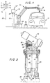
- This installation consists mainly of a polyarticulated arm mechanism 12, of a coating product projector 13 carried by the last segment of this arm, of a coating product changing unit 14 and of a control unit 15 managed by computer .
- the coating products are water-based paints and the sprayer 13 is a pneumatic sprayer. It could be of the electrostatic type on condition of providing isolation and separation means, for example with an intermediate reservoir, between the headlight brought to high voltage and the coating product change unit 14, normally maintained at the potential of Earth.
- This coating product changing unit 14 is conventional and consists of a manifold 18 to which are connected supply valves for different coating products P1-P4 as well as a cleaning product supply valve N and a compressed air supply valve A. All of these valves controlled from the control unit 15 are connected to respective pressure distribution circuits, not shown.
- the poly-articulated arm is mounted on a guide rail 20 parallel to the conveyor 21 carrying the bodies 11. It can move over the entire length of the body and even beyond it to coat its ends.
- the outlet of the manifold 18 is connected to the projector 13 by a distribution duct 22, here made of flexible material and of a sufficient length so as not to impede the movements of the polyarticulated arm 12. Part of this duct 22 therefore passes inside of the arm and crosses all of its articulations up to the last segment 23 of said arm, which carries the headlight 13.
- the installation comprises means for controlling the flow rate of the product delivered to the projector, in the form of a control loop established between the control unit 15, an actuator 25 and a means 26 for measuring the instantaneous flow of product delivered to said projector.
- this measurement means 26, at least, is placed in the vicinity of the projector 13. As shown in FIG. 2, it is carried by the last segment 23 of the polyarticulated arm.
- this sensor is an electromagnetic flowmeter of the type described above.
- This sensor has a coating product inlet 28 to which the conduit 22 is connected and a product outlet 30, connected to the projector, here by means of the actuator 25.
- Such a flow meter receives its electrical power by an electrical line 31 and returns the developed signal, representative of the flow rate, by an electric line 32.
- the latter is connected to a measurement input 33 of the control unit 15.
- the input 28 and the output 30 are interconnected by a simple internal conduit element 35 passing through a magnetic field zone. This duct element introduces practically no additional pressure drop so that the flowmeter can withstand significant flow overloads without bypass, especially during the cycles of changing the coating product and cleaning.
- the actuator 25 is inserted between the flow meter 26 and the projector 13. It operates with adjustable pressure drop.
- a fluid conduit 37 (generally supplied with compressed air) is connected to the unit 15 for piloting said actuator. This duct opens into a chamber 38 partially delimited by a membrane piston 39 which is coupled to a valve 40 placed in the path of the coating product and able to move opposite a fixed seat, to adjust the instantaneous flow rate of the product. The valve is urged upon opening under the action of the piston 39 and upon closing under the action of a spring 42.
- a fluid conduit 45 allows the control of the headlight 13, the spray air and beam conformation are not shown.
- the control unit 15 receives from the computer (not shown) a flow instruction at 47.
- a recovery tank 46 placed at the foot of the polyarticulated arm makes it possible to recover residues of coating product and cleaning product, in particular during a cycle of changing of coating product. The operation is as follows.
- a bodywork is being coated with one of the coating products from one of the P1-P4 valves.
- the product coming from the valve P1 flows into the manifold 18 and the conduit 22 and crosses the flow meter 26 and the actuator 25 before being sprayed by the projector 13.
- the flow meter 26 sends, by the electric line 32, a signal corresponding to the instantaneous flow measured, to the control unit 15 in which it is compared to the set value received at 47.
- the control unit adjusts by the conduit 37 the pressure of the control fluid of the actuator 25 to match the measured value with the set value.
- the sprayer 13 is directed towards constantly variable surfaces and the product flow rate is continuously adjusted by modification of the set value received at 47 and by reaction of the looped system.
- the position of the flowmeter at the end of the poly-articulated arm, that is to say immediately upstream of the projector makes it possible to effectively deal with rapid variations in the desired flow, by eliminating all the possible phase shifts and delays.
- the volume of product contained in the conduit 22 common to all the coating products is of the same order of magnitude as the volume projected on each bodywork.
- the flowmeter and the 'actuator are not disturbed because, because of their position, immediately upstream of the sprayer, they are crossed only by the coating product, until the end of the spraying phase. Then, to finish cleaning the common part of the supply circuit, the spraying is stopped, the flow rate reduced to zero and the sprayer 13 is brought up to the opening of the recovery tank 46. The flow rate is then increased to maximum, until the common area is clean. To save time and save on cleaning product, alternately admit compressed air by opening valve A and closing valve N, then vice versa. When the common part of the circuit is sufficiently clean, it is freed of the residues of cleaning product by opening the valve A after, of course, the last closing of the valve N.
- valve A is closed and the filling of the circuit with a new product begins, by opening another valve P1-P4, for example P2.
- this filling is done at maximum flow using the dispensing pressure of the new coating product and monitoring the appearance of a flow signal on the return electrical line 32.
- the new product reaches the flow meter , it measures a certain uncontrolled flow, but the computer, "informed" by the return signal, takes over control of the actuator 25.
- the projector is then closed and placed in the standby position for a new bodywork. As soon as the latter arrives, a new flow instruction is supplied to the control unit by line 47 and the coating of the new bodywork with the new product can begin, according to a predetermined flow variation law as a function of the expected movements of the polyarticulated arm.
Landscapes
- Spray Control Apparatus (AREA)
- Nozzles (AREA)
- Application Of Or Painting With Fluid Materials (AREA)
Claims (13)
- Spritzanlage für ein durch Sprühen aufzutragendes Beschichtungsmaterial mit wenigstens einer Spritzeinrich- tung (13) für ein derartiges Material, mit Durchflußregelungsmitteln für das der Spritzeinrichtung zugeführte Material, umfassend ein Betätigungsorgan (25) und eine Durchflußmeßeinrichtung (26), und mit einer Verteilungsleitung (22), die zumindest eines der Regelmittel mit einer Zuführeinrichtung für das Beschichtungsmaterial verbindet, dadurch gekennzeichnet, daß zumindest die Durchflußmeßeinrichtung (26) stromauf von der Verteilungsleitung (22) und benachbart zu der Spritzeinrichtung (13) angeordnet ist.
- Anlage nach Anspruch 1, dadurch gekennzeichnet, daß die Zufuhreinrichtung für das Beschichtungsmaterial in an sich bekannter Weise eine Einheit (14) zum Wechseln des Beschichtungsmaterials und zum Zuführen eines Spül- und/oder Blasproduktes umfaßt.
- Anlage nach Anspruch 1 oder 2, dadurch gekennzeichnet, daß das Betätigungsorgan (25) benachbart zur Spritzeinrichtung angeordnet ist.
- Anlage nach Anspruch 3, dadurch gekennzeichnet, daß das Betätigungsorgan (25) ein an sich bekanntes Druckregelorgan ist.
- Anlage nach Anspruch 1, dadurch gekennzeichnet, daß das Betätigungsorgan (25) für die Durchflußregelungsmittel stromauf von der Verteilungsleitung (22) angeordnet ist.
- Anlage nach Anspruch 5, dadurch gekennzeichnet, daß das Betätigungsorgan (25) eine Pumpe ist.
- Anlage nach einem der vorangehenden Ansprüche, wobei die Spritzeinrichtung durch einen beweglichen Träger (12) getragen ist, dadurch gekennzeichnet, daß die Durchflußmeßeinrichtung (26) an demselben beweglichen Träger sitzt.
- Anlage nach einem der Ansprüche 1 bis 3, bei der die Spritzeinrichtung durch einen beweglichen Träger (12) getragen ist, dadurch gekennzeichnet, daß das Betätigungsorgan (25) an demselben beweglichen Träger sitzt.
- Vorrichtung nach einem der vorangehenden Ansprüche, dadurch gekennzeichnet, daß die Durchflußmeßeinrichtung ein elektromagnetischer Durchflußmesser (26) ist.
- Anlage nach einem der Ansprüche 1 bis 8, dadurch gekennzeichnet, daß die Durchflußmeßeinrichtung ein Zahnraddurchflußmesser ist.
- Anlage nach einem der Ansprüche 1 bis 8, dadurch gekennzeichnet, daß die Durchflußmeßeinrichtung ein Ultraschalldurchflußmesser ist.
- Anlage nach einem der Ansprüche 1 bis 8, dadurch gekennzeichnet, daß die Durchflußmeßeinrichtung ein thermischer Durchflußmesser ist.
- Anlage nach Anspruch 7 oder 8, dadurch gekennzeichnet, daß der bewegliche Träger einen mit mehreren Gelenken versehenen Arm (12) umfaßt, daß die Spritzeinrichtung auf dem letzten Element (23) dieses Armes angebracht ist, und daß die Durchflußmeßeinrichtung und/oder das Betätigungsorgan durch diesen Arm, bevorzugt durch das letzte Element (23) getragen sind.
Applications Claiming Priority (2)
| Application Number | Priority Date | Filing Date | Title |
|---|---|---|---|
| FR9006770A FR2662620A1 (fr) | 1990-05-31 | 1990-05-31 | Installation de projection de produit de revetement pulverise a debit controle. |
| FR9006770 | 1990-05-31 |
Publications (2)
| Publication Number | Publication Date |
|---|---|
| EP0459892A1 EP0459892A1 (de) | 1991-12-04 |
| EP0459892B1 true EP0459892B1 (de) | 1994-08-03 |
Family
ID=9397135
Family Applications (1)
| Application Number | Title | Priority Date | Filing Date |
|---|---|---|---|
| EP91401378A Expired - Lifetime EP0459892B1 (de) | 1990-05-31 | 1991-05-29 | Farbspritzanlage mit kontrolliertem Durchfluss |
Country Status (6)
| Country | Link |
|---|---|
| EP (1) | EP0459892B1 (de) |
| JP (1) | JPH04227872A (de) |
| CA (1) | CA2043549A1 (de) |
| DE (1) | DE69103218T2 (de) |
| ES (1) | ES2059078T3 (de) |
| FR (1) | FR2662620A1 (de) |
Families Citing this family (20)
| Publication number | Priority date | Publication date | Assignee | Title |
|---|---|---|---|---|
| DE4242715C2 (de) * | 1991-12-17 | 2000-05-31 | Krautzberger Gmbh | Adapter mit Regelventil für automatische Material-Spritzvorrichtung |
| DE4418288A1 (de) * | 1994-05-26 | 1995-11-30 | Gema Volstatic Ag | Elektrostatische Sprühvorrichtung |
| FR2732908B1 (fr) * | 1995-04-11 | 1997-05-16 | Sames Sa | Procede et dispositif de changement de produit dans une installation de projection de produits de revetement |
| DE19546970B4 (de) * | 1995-12-15 | 2006-08-17 | Itw Gema Ag | Pulversprühvorrichtung zur elektrostatischen Sprühbeschichtung |
| DE19649538A1 (de) * | 1996-11-29 | 1998-06-04 | Eisenmann Kg Maschbau | Verfahren zum Aufbringen von Spritzapplikationen o. dgl. vornehmlich auf Fahrzeugkarossen und Vorrichtung zur Verfahrensdurchführung |
| DE19654514A1 (de) * | 1996-12-27 | 1998-07-02 | Itw Oberflaechentechnik Gmbh | Sprühbeschichtungseinrichtung |
| DE19742588B4 (de) * | 1997-09-26 | 2009-02-19 | Dürr Systems GmbH | Verfahren zum serienweisen Beschichten von Werkstücken |
| DE19916761A1 (de) | 1999-04-14 | 2000-11-02 | Klaschka Gmbh & Co | Verfahren und Vorrichtung zum Besprühen von Werkstücken |
| US20050056212A1 (en) * | 2003-09-15 | 2005-03-17 | Schaupp John F. | Split shroud for coating dispensing equipment |
| EP1772194B1 (de) | 2005-10-07 | 2019-01-09 | Dürr Systems AG | Beschichtungsmittel-Versorgungseinrichtung und zugehöriges Betriebsverfahren |
| DE102006021623A1 (de) | 2006-05-09 | 2007-11-15 | Dürr Systems GmbH | Dosiersystem für eine Beschichtungsanlage |
| ES2534328T3 (es) | 2006-12-12 | 2015-04-21 | Dürr Systems GmbH | Dispositivo de revestimiento con un dispositivo de dosificación |
| DE102006058562A1 (de) | 2006-12-12 | 2008-08-14 | Dürr Systems GmbH | Beschichtungseinrichtung mit einer Dosiervorrichtung |
| DE102007029195A1 (de) | 2007-06-25 | 2009-02-19 | Dürr Systems GmbH | Beschichtungseinrichtung mit einer Dosiervorrichtung |
| DE102007053578A1 (de) * | 2007-11-07 | 2009-05-14 | ITW Oberflächentechnik GmbH & Co. KG | Automatischer Spritzapparat für Beschichtungsflüssigkeit und seine Kombination mit einem Roboter |
| EP2358481B1 (de) | 2008-12-19 | 2015-12-02 | Dürr Systems GmbH | Lackieranlage und verfahren zum betreiben einer lackieranlage |
| DE102008064043A1 (de) * | 2008-12-19 | 2010-07-01 | Dürr Systems GmbH | Lackiervorrichtung und Verfahren zu deren Betrieb |
| CN103223777B (zh) * | 2013-05-16 | 2015-08-26 | 汕头市俊国机电科技有限公司 | 一种便携式钢板面喷装置用的喷头总成 |
| WO2022010992A1 (en) * | 2020-07-08 | 2022-01-13 | Spraying Systems Co. | Electrostatic sprayer in-line flow measurement arrangement |
| CN117299420A (zh) * | 2023-10-07 | 2023-12-29 | 科菲亚重型装备有限公司 | 一种风电叶片的自动喷涂装置及其喷涂工艺 |
Family Cites Families (5)
| Publication number | Priority date | Publication date | Assignee | Title |
|---|---|---|---|---|
| IT1186183B (it) * | 1985-11-08 | 1987-11-18 | Gaiotto Impianti Spa | Equilibratore di pressione per alimentatori di smalto ceramico o vernici in genere per pistole a spruzzo in genere,ed in particolare per pistole a spruzzo automatiche installate su robot di smaltatura o verniciatura |
| FR2616086B2 (fr) * | 1987-05-19 | 1990-01-26 | Sames Sa | Installation de projection de produit de revetement, a pompe |
| FR2618087B1 (fr) * | 1987-07-15 | 1990-02-23 | Graco France Sa | Procede de selection d'un fluide avec commande et regulation de son debit et dispositif mettant en oeuvre le procede et installation d'application de peinture avec selection de couleur mettant en oeuvre le procede |
| DE3822835A1 (de) * | 1988-07-06 | 1990-03-08 | Josef Schucker | Verfahren und anordnung zum lackieren von werkstueckoberflaechen |
| US4878454A (en) * | 1988-09-16 | 1989-11-07 | Behr Industrial Equipment Inc. | Electrostatic painting apparatus having optically sensed flow meter |
-
1990
- 1990-05-31 FR FR9006770A patent/FR2662620A1/fr active Granted
-
1991
- 1991-05-29 ES ES91401378T patent/ES2059078T3/es not_active Expired - Lifetime
- 1991-05-29 DE DE69103218T patent/DE69103218T2/de not_active Expired - Fee Related
- 1991-05-29 EP EP91401378A patent/EP0459892B1/de not_active Expired - Lifetime
- 1991-05-30 CA CA002043549A patent/CA2043549A1/fr not_active Abandoned
- 1991-05-31 JP JP3156170A patent/JPH04227872A/ja active Pending
Also Published As
| Publication number | Publication date |
|---|---|
| EP0459892A1 (de) | 1991-12-04 |
| ES2059078T3 (es) | 1994-11-01 |
| FR2662620A1 (fr) | 1991-12-06 |
| FR2662620B1 (de) | 1995-02-17 |
| JPH04227872A (ja) | 1992-08-17 |
| DE69103218T2 (de) | 1994-12-08 |
| CA2043549A1 (fr) | 1991-12-01 |
| DE69103218D1 (de) | 1994-09-08 |
Similar Documents
| Publication | Publication Date | Title |
|---|---|---|
| EP0459892B1 (de) | Farbspritzanlage mit kontrolliertem Durchfluss | |
| EP0300902B1 (de) | Handgesteuerte Sprühanlage und Druckluftsprühpistole für ein Beschichtungsprodukt | |
| EP0527678B1 (de) | Verfahren zur Durchflussmessung fluidisierten Pulvers und Durchflussmessvorrichtung zur Durchführung dieses Verfahrens | |
| BE1013809A3 (fr) | Procede de controle du bon fonctionnement du systeme de recuperation de vapeur emise dans une installation de distribution de carburant ainsi qu'installation permettant la mise en oeuvre de ce procede. | |
| FR2683789A1 (fr) | Interrupteur de limite inferieure du pas, a commande hydraulique, pour un dispositif de variation du pas d'une helice. | |
| CA2760378A1 (fr) | Procede et dispositif pour alimenter une chambre de combustion de turbomachine avec un debit de carburant regule | |
| FR2964887A1 (fr) | Dispositif de thermonebulisation d'un liquide et procede associe | |
| FR2684445A1 (fr) | Dispositif de maintien d'un niveau predetermine d'un liquide, notamment de l'encre d'impression ou de la peinture, dans un conteneur. | |
| CA2774320C (fr) | Doseur de carburant ayant un dispositif de regulation ameliore | |
| FR2484494A1 (fr) | Dispositif pour la regularisation de la couche de substance constituant la signalisation horizontale des routes et marquages analogues | |
| FR3097826A1 (fr) | Dispositif et procédé de nettoyage d'une pluralité de capteurs/émetteurs d'un véhicule automobile | |
| EP0123581A1 (de) | Pulverspender, insbesondere für eine Heizpistole | |
| FR2708215A1 (fr) | Système de plusieurs constituants à base d'eau et procédé de pulvérisation électrostatique d'une peinture à base d'eau. | |
| FR2474192A1 (fr) | Dispositif de reglage par reaction de la vitesse d'un moteur | |
| EP0704249B1 (de) | Vorrichtung zur Verteilung pulverförmiger Feststoffe auf der Oberfläche eines Substrats zur Beschichtung dieses Substrates | |
| EP0003703B1 (de) | Verfahren und Einrichtung zur Regelung des Flusses von evoluierenden Breien am Auslass eines Behälters | |
| EP0411098B1 (de) | Farbspritzanlage mit kontrolliertem durchfluss | |
| FR2924706A1 (fr) | Installation de distribution de carburant renfermant un dispsositif de recuperation de vapeurs ainsi que procede mis en oeuvre lors de l'utilisation de cette installation. | |
| EP0703832A1 (de) | Zuführungs-vorrichtung und verfahren einer spritzanlage für ein pulverförmiges material | |
| EP1866098B1 (de) | Vorrichtung zum elektrostatischen aufbringen eines beschichtungsmaterials und verfahren zur steuerung der stromversorgung des spannungserhöhers dieser vorrichtung | |
| EP2983831B1 (de) | Vorrichtung zum elektrostatischen besprühen eines beschichtungsprodukts und verfahren zur generatorsteuerung zur stromversorgung einer hochspannungseinheit in solch einer vorrichtung | |
| WO2005016549A2 (fr) | Dispositif de diffusion d'un liquide dans l'atmosphere incorporant des moyens vibratoires de debouchage d'une buse de pulverisation | |
| FR2751030A1 (fr) | Regulateur de carburant pour turboreacteur | |
| EP0737520A1 (de) | Verfahren und Vorrichtung zum Wechseln von Beschichtungsmaterial in einer Anlage zum Spritzen von Beschichtungsmaterial | |
| FR2796635A1 (fr) | Procede de controle du bon fonctionnement du systeme de recuperation de vapeur emise dans une installation de distribution de carburant ainsi qu'installation permettant la mise en oeuvre de ce procede |
Legal Events
| Date | Code | Title | Description |
|---|---|---|---|
| PUAI | Public reference made under article 153(3) epc to a published international application that has entered the european phase |
Free format text: ORIGINAL CODE: 0009012 |
|
| AK | Designated contracting states |
Kind code of ref document: A1 Designated state(s): BE DE ES GB IT NL SE |
|
| 17P | Request for examination filed |
Effective date: 19920109 |
|
| 17Q | First examination report despatched |
Effective date: 19930217 |
|
| GRAA | (expected) grant |
Free format text: ORIGINAL CODE: 0009210 |
|
| AK | Designated contracting states |
Kind code of ref document: B1 Designated state(s): BE DE ES GB IT NL SE |
|
| PG25 | Lapsed in a contracting state [announced via postgrant information from national office to epo] |
Ref country code: IT Free format text: LAPSE BECAUSE OF FAILURE TO SUBMIT A TRANSLATION OF THE DESCRIPTION OR TO PAY THE FEE WITHIN THE PRE;WARNING: LAPSES OF ITALIAN PATENTS WITH EFFECTIVE DATE BEFORE 2007 MAY HAVE OCCURRED AT ANY TIME BEFORE 2007. THE CORRECT EFFECTIVE DATE MAY BE DIFFERENT FROM THE ONE RECORDED.SCRIBED TIME-LIMIT Effective date: 19940803 Ref country code: NL Effective date: 19940803 |
|
| GBT | Gb: translation of ep patent filed (gb section 77(6)(a)/1977) |
Effective date: 19940803 |
|
| REF | Corresponds to: |
Ref document number: 69103218 Country of ref document: DE Date of ref document: 19940908 |
|
| REG | Reference to a national code |
Ref country code: ES Ref legal event code: FG2A Ref document number: 2059078 Country of ref document: ES Kind code of ref document: T3 |
|
| PG25 | Lapsed in a contracting state [announced via postgrant information from national office to epo] |
Ref country code: SE Effective date: 19941103 |
|
| NLV1 | Nl: lapsed or annulled due to failure to fulfill the requirements of art. 29p and 29m of the patents act | ||
| PLBE | No opposition filed within time limit |
Free format text: ORIGINAL CODE: 0009261 |
|
| STAA | Information on the status of an ep patent application or granted ep patent |
Free format text: STATUS: NO OPPOSITION FILED WITHIN TIME LIMIT |
|
| 26N | No opposition filed | ||
| REG | Reference to a national code |
Ref country code: GB Ref legal event code: IF02 |
|
| PGFP | Annual fee paid to national office [announced via postgrant information from national office to epo] |
Ref country code: ES Payment date: 20020521 Year of fee payment: 12 |
|
| PGFP | Annual fee paid to national office [announced via postgrant information from national office to epo] |
Ref country code: GB Payment date: 20020618 Year of fee payment: 12 |
|
| PGFP | Annual fee paid to national office [announced via postgrant information from national office to epo] |
Ref country code: BE Payment date: 20020701 Year of fee payment: 12 |
|
| PG25 | Lapsed in a contracting state [announced via postgrant information from national office to epo] |
Ref country code: GB Free format text: LAPSE BECAUSE OF NON-PAYMENT OF DUE FEES Effective date: 20030529 |
|
| PG25 | Lapsed in a contracting state [announced via postgrant information from national office to epo] |
Ref country code: ES Free format text: LAPSE BECAUSE OF NON-PAYMENT OF DUE FEES Effective date: 20030530 |
|
| PG25 | Lapsed in a contracting state [announced via postgrant information from national office to epo] |
Ref country code: BE Free format text: LAPSE BECAUSE OF NON-PAYMENT OF DUE FEES Effective date: 20030531 |
|
| BERE | Be: lapsed |
Owner name: S.A. *SAMES Effective date: 20030531 |
|
| GBPC | Gb: european patent ceased through non-payment of renewal fee |
Effective date: 20030529 |
|
| PGFP | Annual fee paid to national office [announced via postgrant information from national office to epo] |
Ref country code: DE Payment date: 20040609 Year of fee payment: 14 |
|
| REG | Reference to a national code |
Ref country code: ES Ref legal event code: FD2A Effective date: 20030530 |
|
| PG25 | Lapsed in a contracting state [announced via postgrant information from national office to epo] |
Ref country code: DE Free format text: LAPSE BECAUSE OF NON-PAYMENT OF DUE FEES Effective date: 20051201 |