EP0459431A2 - Tête de mesure à ultrasons pour milieux chauds - Google Patents
Tête de mesure à ultrasons pour milieux chauds Download PDFInfo
- Publication number
- EP0459431A2 EP0459431A2 EP19910108759 EP91108759A EP0459431A2 EP 0459431 A2 EP0459431 A2 EP 0459431A2 EP 19910108759 EP19910108759 EP 19910108759 EP 91108759 A EP91108759 A EP 91108759A EP 0459431 A2 EP0459431 A2 EP 0459431A2
- Authority
- EP
- European Patent Office
- Prior art keywords
- liquid
- membrane
- ultrasonic
- damping body
- piezo element
- Prior art date
- Legal status (The legal status is an assumption and is not a legal conclusion. Google has not performed a legal analysis and makes no representation as to the accuracy of the status listed.)
- Granted
Links
- 239000000523 sample Substances 0.000 title claims abstract description 18
- 239000007788 liquid Substances 0.000 claims abstract description 28
- 239000011521 glass Substances 0.000 claims abstract description 20
- 238000013016 damping Methods 0.000 claims abstract description 17
- 239000012528 membrane Substances 0.000 claims abstract description 17
- 239000011701 zinc Substances 0.000 claims abstract description 17
- HCHKCACWOHOZIP-UHFFFAOYSA-N Zinc Chemical compound [Zn] HCHKCACWOHOZIP-UHFFFAOYSA-N 0.000 claims abstract description 16
- 229910052725 zinc Inorganic materials 0.000 claims abstract description 16
- 238000012360 testing method Methods 0.000 claims abstract description 14
- 238000005259 measurement Methods 0.000 claims abstract description 10
- 229910052751 metal Inorganic materials 0.000 claims description 8
- 239000002184 metal Substances 0.000 claims description 8
- 239000000463 material Substances 0.000 abstract description 5
- 238000001816 cooling Methods 0.000 abstract description 4
- 238000002604 ultrasonography Methods 0.000 description 10
- PCHJSUWPFVWCPO-UHFFFAOYSA-N gold Chemical compound [Au] PCHJSUWPFVWCPO-UHFFFAOYSA-N 0.000 description 5
- 239000004020 conductor Substances 0.000 description 4
- 230000008878 coupling Effects 0.000 description 4
- 238000010168 coupling process Methods 0.000 description 4
- 238000005859 coupling reaction Methods 0.000 description 4
- 239000010935 stainless steel Substances 0.000 description 4
- 229910001220 stainless steel Inorganic materials 0.000 description 4
- PNEYBMLMFCGWSK-UHFFFAOYSA-N aluminium oxide Inorganic materials [O-2].[O-2].[O-2].[Al+3].[Al+3] PNEYBMLMFCGWSK-UHFFFAOYSA-N 0.000 description 3
- 229910052593 corundum Inorganic materials 0.000 description 3
- 239000011888 foil Substances 0.000 description 3
- 238000005246 galvanizing Methods 0.000 description 3
- 239000003921 oil Substances 0.000 description 3
- 230000005236 sound signal Effects 0.000 description 3
- 230000009466 transformation Effects 0.000 description 3
- 229910001845 yogo sapphire Inorganic materials 0.000 description 3
- 229910000831 Steel Inorganic materials 0.000 description 2
- 229910001297 Zn alloy Inorganic materials 0.000 description 2
- 230000015572 biosynthetic process Effects 0.000 description 2
- 239000013078 crystal Substances 0.000 description 2
- 238000002592 echocardiography Methods 0.000 description 2
- 238000005516 engineering process Methods 0.000 description 2
- GQYHUHYESMUTHG-UHFFFAOYSA-N lithium niobate Chemical compound [Li+].[O-][Nb](=O)=O GQYHUHYESMUTHG-UHFFFAOYSA-N 0.000 description 2
- FUJCRWPEOMXPAD-UHFFFAOYSA-N lithium oxide Chemical class [Li+].[Li+].[O-2] FUJCRWPEOMXPAD-UHFFFAOYSA-N 0.000 description 2
- 239000000155 melt Substances 0.000 description 2
- 238000002844 melting Methods 0.000 description 2
- 230000008018 melting Effects 0.000 description 2
- 239000011148 porous material Substances 0.000 description 2
- 239000007787 solid Substances 0.000 description 2
- 239000010959 steel Substances 0.000 description 2
- DGAQECJNVWCQMB-PUAWFVPOSA-M Ilexoside XXIX Chemical compound C[C@@H]1CC[C@@]2(CC[C@@]3(C(=CC[C@H]4[C@]3(CC[C@@H]5[C@@]4(CC[C@@H](C5(C)C)OS(=O)(=O)[O-])C)C)[C@@H]2[C@]1(C)O)C)C(=O)O[C@H]6[C@@H]([C@H]([C@@H]([C@H](O6)CO)O)O)O.[Na+] DGAQECJNVWCQMB-PUAWFVPOSA-M 0.000 description 1
- KKCBUQHMOMHUOY-UHFFFAOYSA-N Na2O Inorganic materials [O-2].[Na+].[Na+] KKCBUQHMOMHUOY-UHFFFAOYSA-N 0.000 description 1
- OAICVXFJPJFONN-UHFFFAOYSA-N Phosphorus Chemical compound [P] OAICVXFJPJFONN-UHFFFAOYSA-N 0.000 description 1
- QVGXLLKOCUKJST-UHFFFAOYSA-N atomic oxygen Chemical compound [O] QVGXLLKOCUKJST-UHFFFAOYSA-N 0.000 description 1
- 239000000919 ceramic Substances 0.000 description 1
- 238000004590 computer program Methods 0.000 description 1
- 239000007822 coupling agent Substances 0.000 description 1
- 230000006378 damage Effects 0.000 description 1
- 230000007423 decrease Effects 0.000 description 1
- 230000001066 destructive effect Effects 0.000 description 1
- 238000009792 diffusion process Methods 0.000 description 1
- XUCJHNOBJLKZNU-UHFFFAOYSA-M dilithium;hydroxide Chemical compound [Li+].[Li+].[OH-] XUCJHNOBJLKZNU-UHFFFAOYSA-M 0.000 description 1
- 239000003925 fat Substances 0.000 description 1
- 239000010931 gold Substances 0.000 description 1
- 229910052737 gold Inorganic materials 0.000 description 1
- 239000004519 grease Substances 0.000 description 1
- 238000011835 investigation Methods 0.000 description 1
- 239000007791 liquid phase Substances 0.000 description 1
- 229910001947 lithium oxide Inorganic materials 0.000 description 1
- 239000000203 mixture Substances 0.000 description 1
- 238000013021 overheating Methods 0.000 description 1
- 229910052760 oxygen Inorganic materials 0.000 description 1
- 239000001301 oxygen Substances 0.000 description 1
- 230000035699 permeability Effects 0.000 description 1
- 239000012071 phase Substances 0.000 description 1
- 239000011574 phosphorus Substances 0.000 description 1
- 229910001392 phosphorus oxide Inorganic materials 0.000 description 1
- 230000001681 protective effect Effects 0.000 description 1
- 230000036632 reaction speed Effects 0.000 description 1
- 239000011734 sodium Substances 0.000 description 1
- 229910001948 sodium oxide Inorganic materials 0.000 description 1
- 238000003466 welding Methods 0.000 description 1
Images
Classifications
-
- G—PHYSICS
- G01—MEASURING; TESTING
- G01B—MEASURING LENGTH, THICKNESS OR SIMILAR LINEAR DIMENSIONS; MEASURING ANGLES; MEASURING AREAS; MEASURING IRREGULARITIES OF SURFACES OR CONTOURS
- G01B17/00—Measuring arrangements characterised by the use of infrasonic, sonic or ultrasonic vibrations
- G01B17/02—Measuring arrangements characterised by the use of infrasonic, sonic or ultrasonic vibrations for measuring thickness
Definitions
- the present invention relates to an ultrasonic hot probe for non-contact testing of components in a hot liquid, in particular for measuring the wall thickness of containers which contain liquid zinc of approximately 450 ° C., with a housing that can be immersed in the liquid and a piezo element coupled therein in terms of sound technology , a damping body and a membrane adjacent to the liquid.
- a non-destructive measurement of wall thickness from the outside - eg with ultrasound - is only possible at certain points due to the walling of the tub by flaps in the masonry.
- the tub is pumped empty so that the wall thickness can be measured from the inside when it is cold. For cost reasons, this can only be done at relatively large intervals (approx. 1 to 2 years).
- an attempt is made to measure the wall thickness from the liquid zinc during operation.
- a outside the molten zinc arranged, cooled probe is described which, ultrasonic pulses through übe described with a long delay line made of stainless steel, which has a 45 o -Umlenk Structure by the molten metal to a sample and receives its echo.
- the object of the present invention is to provide an ultrasonic hot probe for the contact-free testing of components in a hot liquid, in particular for measuring the wall thickness of containers which contain liquid zinc of approximately 450 ° C., with a housing which can be immersed in the liquid and is soundproofed therein coupled a piezo element, a damping body and a membrane adjacent to the liquid.
- This ultrasonic hot probe which can be completely immersed in the liquid, is intended to generate a sufficiently strong sound signal and must do without cooling, that is to say it consist of temperature-resistant materials.
- an ultrasonic hot probe is proposed according to the invention with a housing which can be immersed in the liquid and is acoustically coupled therein to a piezo element, a damping body and a membrane adjacent to the liquid and in between each with a glass layer which is soft during the measurement.
- a glass layer which is soft during the measurement.
- a sufficient acoustic coupling between the parts mentioned is achieved, as is otherwise only known for oils or fats, the temperature resistance of which, however, is not sufficient for the present case.
- all parts can be made from materials that can withstand high thermal loads. Furthermore, they are pressed together only with moderate force, so that they are not exposed to particularly high mechanical loads.
- the membrane can be made as thin-walled as the end of the test head to the outside, as is desired for reasons of sound engineering.
- the glass used has a melting point that is slightly below the operating temperature of the liquid. Also have they have a coefficient of thermal expansion in the solid state, which does not differ significantly from the adjacent components, so that they also avoid destruction when cooling. So far, a glass has proven to be useful which contains sodium, phosphorus and lithium oxides. A mixture in molar percentages of 25% Na2O and Li2O with 50% P2O5 has proven itself. This has a melting point of about 380 o C and in the solid state has a thermal expansion coefficient adapted to the adjacent components.
- a thin, reverberant layer for example a gold foil, which is provided on both sides with the glass layer mentioned above, which is soft during the measurement.
- a gold foil of 10 ⁇ m with glass layers of 50 ⁇ m has proven to be expedient.
- the piezo element can consist of lithium niobate, which has a high temperature resistance.
- an oxygen-containing atmosphere is required above 300 o C.
- the interior of the test head must therefore have an air-permeable connection to the outside, for example via the cable routing.
- the membrane in a manner known per se, has a thickness that is not greater than half the wavelength of the ultrasound test frequency.
- a lambda / 2 membrane at 2 MHz and 450 o C has a thickness of 1.38 mm, which can only be achieved in the present case if a good coupling is achieved with the help of the glass layers mentioned above and thus dispenses with high contact forces can be.
- the damping body consists of sintered metal which is sealed off from the glass layer.
- the sintered metal consists for example of a stainless steel 1.4404 with an average grain size of 0.05 to 0.1 mm and a pososity of 30 to 50%. So that the above-mentioned soft glass layer does not penetrate into the pores, the surface of the sintered metal is ground to the glass layer so that the pores close.
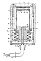
- the figure shows an embodiment of the invention.
- the cylindrical housing 1 is closed on one side with a thin-walled membrane 2 made of stainless steel and on the other side with a cover 3.
- a gold foil 4 with a thickness of 50 ⁇ m is coupled with a glass layer 5 to the membrane 2 and with a further glass layer 6 to the piezo element 7 made of lithium niobate, which in turn is connected with a further glass layer 8, a further gold foil 9 and one Glass layer 10 is coupled to the damping body 11 made of a sintered metal (stainless steel 1.4404 with an average grain size of 0.05 to 0.1 mm).
- the glass layers are all 50 ⁇ m thick.
- the gold foils 4 and 9 favor the phase behavior and the permeability factor of the sound signal.
- the damping body 11 is surrounded together with the piezo element 7 by a cylindrical insulating ring 12 made of Al2O3 and carries on its back an insulating disc 13, also made of Al2O3. These parts are pressed in a manner known per se with the pressure piece 21 and the plate springs 14, which are guided on the pressure stamp 22, and with the adjustable screw ring 15 via the disk 23 fastened to the pressure stamp 22.
- the disk-shaped piezo element 7 is tapped capacitively via its two end faces.
- the inside of the membrane 2 and the electrically conductive damping body 11 serve as electrodes.
- the coaxial signal conductor 16 (mineral-insulated sheath measuring conductor) is guided to the outside with its sheath 17 and connected to the damping body 11 by laser welding spot 18.
- the protective tube 19 is welded tightly to the cover 3 and surrounds the signal conductor 16 and its jacket 17 at a distance.
- the membrane 2, which is conical at the edge, is pressed with a screw ring 20 from the inside against a conical shoulder in the housing 1 and then welded tightly.
- the signal conductor 16 is surrounded by an insulating tube 24 within the housing 1.
- damping bodies made of ceramic, for example Al2O3, or from a bundle of parallel wires embedded in a steel sleeve, which are soldered or welded together at the front, are possible.
- the acoustic wave resistance of the damping body should be selected in a manner known per se so that it is in connection with the front acoustic coupling layer leads to a short, i.e. broadband ultrasound pulse.
- the hot probe according to the invention works in pulse-echo mode as a transmitter and as a receiver.
Landscapes
- Physics & Mathematics (AREA)
- General Physics & Mathematics (AREA)
- Transducers For Ultrasonic Waves (AREA)
- Investigating Or Analyzing Materials By The Use Of Ultrasonic Waves (AREA)
- Thermotherapy And Cooling Therapy Devices (AREA)
- Investigating Or Analyzing Materials Using Thermal Means (AREA)
- Ultra Sonic Daignosis Equipment (AREA)
- Length Measuring Devices Characterised By Use Of Acoustic Means (AREA)
Applications Claiming Priority (2)
| Application Number | Priority Date | Filing Date | Title |
|---|---|---|---|
| DE9006170U | 1990-05-31 | ||
| DE9006170 | 1990-05-31 |
Publications (3)
| Publication Number | Publication Date |
|---|---|
| EP0459431A2 true EP0459431A2 (fr) | 1991-12-04 |
| EP0459431A3 EP0459431A3 (en) | 1992-08-05 |
| EP0459431B1 EP0459431B1 (fr) | 1994-10-19 |
Family
ID=6854284
Family Applications (1)
| Application Number | Title | Priority Date | Filing Date |
|---|---|---|---|
| EP91108759A Expired - Lifetime EP0459431B1 (fr) | 1990-05-31 | 1991-05-29 | Tête de mesure à ultrasons pour milieux chauds |
Country Status (3)
| Country | Link |
|---|---|
| EP (1) | EP0459431B1 (fr) |
| AT (1) | ATE113122T1 (fr) |
| DE (2) | DE9106613U1 (fr) |
Cited By (4)
| Publication number | Priority date | Publication date | Assignee | Title |
|---|---|---|---|---|
| DE4240719C1 (de) * | 1992-12-03 | 1994-01-27 | Siemens Ag | Ultraschall-Wandler mit Dämpfungskörper für hohe Arbeitstemperaturen |
| EP2093563A3 (fr) * | 2008-02-22 | 2013-01-02 | Fraunhofer-Gesellschaft zur Förderung der angewandten Forschung e.V. | Dispositif et procédé pour la surveillance ultrasonore d'une éprouvette chaude quant à des défauts du matériau ainsi que procédé de fabrication |
| WO2022223299A1 (fr) | 2021-04-20 | 2022-10-27 | Flexim Flexible Industriemesstechnik Gmbh | Procédé et agencement d'assemblage d'un matériau piézoélectrique pour une large plage de températures |
| RU238139U1 (ru) * | 2025-07-15 | 2025-10-17 | Федеральное государственное автономное образовательное учреждение высшего образования "Санкт-Петербургский государственный электротехнический университет "ЛЭТИ" им. В.И. Ульянова (Ленина)" | Ультразвуковой датчик для неразрушающего контроля толщины стенок ванн горячего цинкования |
Families Citing this family (2)
| Publication number | Priority date | Publication date | Assignee | Title |
|---|---|---|---|---|
| DE102004044071B3 (de) * | 2004-09-11 | 2006-04-13 | Intelligendt Systems & Services Gmbh & Co Kg | Ultraschallprüfvorrichtung und Ultraschallprüfverfahren |
| CN113607211A (zh) * | 2021-07-20 | 2021-11-05 | 广西合创检测技术有限公司 | 一种环境检测仪 |
Family Cites Families (2)
| Publication number | Priority date | Publication date | Assignee | Title |
|---|---|---|---|---|
| DE6944431U (de) * | 1969-11-13 | 1970-04-16 | J U H Krautkraemer Ges Fuer El | Ultraschall-pruefkopf |
| DE3330411A1 (de) * | 1983-08-23 | 1985-03-14 | Siemens AG, 1000 Berlin und 8000 München | Piezo-wandler |
-
1991
- 1991-05-29 AT AT91108759T patent/ATE113122T1/de not_active IP Right Cessation
- 1991-05-29 DE DE9106613U patent/DE9106613U1/de not_active Expired - Lifetime
- 1991-05-29 EP EP91108759A patent/EP0459431B1/fr not_active Expired - Lifetime
- 1991-05-29 DE DE59103262T patent/DE59103262D1/de not_active Expired - Fee Related
Cited By (5)
| Publication number | Priority date | Publication date | Assignee | Title |
|---|---|---|---|---|
| DE4240719C1 (de) * | 1992-12-03 | 1994-01-27 | Siemens Ag | Ultraschall-Wandler mit Dämpfungskörper für hohe Arbeitstemperaturen |
| EP2093563A3 (fr) * | 2008-02-22 | 2013-01-02 | Fraunhofer-Gesellschaft zur Förderung der angewandten Forschung e.V. | Dispositif et procédé pour la surveillance ultrasonore d'une éprouvette chaude quant à des défauts du matériau ainsi que procédé de fabrication |
| WO2022223299A1 (fr) | 2021-04-20 | 2022-10-27 | Flexim Flexible Industriemesstechnik Gmbh | Procédé et agencement d'assemblage d'un matériau piézoélectrique pour une large plage de températures |
| RU238139U1 (ru) * | 2025-07-15 | 2025-10-17 | Федеральное государственное автономное образовательное учреждение высшего образования "Санкт-Петербургский государственный электротехнический университет "ЛЭТИ" им. В.И. Ульянова (Ленина)" | Ультразвуковой датчик для неразрушающего контроля толщины стенок ванн горячего цинкования |
| RU2856796C1 (ru) * | 2025-11-07 | 2026-02-24 | Федеральное государственное автономное образовательное учреждение высшего образования "Санкт-Петербургский государственный электротехнический университет "ЛЭТИ" им. В.И. Ульянова (Ленина)" | Способ ультразвукового измерения толщины стенок ванн горячего цинкования |
Also Published As
| Publication number | Publication date |
|---|---|
| EP0459431B1 (fr) | 1994-10-19 |
| DE59103262D1 (de) | 1994-11-24 |
| DE9106613U1 (de) | 1991-10-10 |
| EP0459431A3 (en) | 1992-08-05 |
| ATE113122T1 (de) | 1994-11-15 |
Similar Documents
| Publication | Publication Date | Title |
|---|---|---|
| EP0040390B1 (fr) | Détecteur de pression pour un moteur à combustion interne | |
| EP0031049B1 (fr) | Transducteur acoustique | |
| EP2382620B1 (fr) | Tête de contrôle à ultrasons | |
| EP2158456B1 (fr) | Capteur à ultrasons destiné à mesurer des vitesses d'écoulement dans des substances fondues fluides | |
| EP2335064B1 (fr) | Méthode par impulsion-écho au moyen d'un réseau de transducteurs et avec compensation thermique | |
| DE19542525C2 (de) | Mikrowellenfenster | |
| DE3732219A1 (de) | Anwendung des verfahrens zur elektromagnetischen ultraschall-wandlung zur ueberwachung von fuellhoehe und blasenbildung in fluessigkeit enthaltenden umschliessungen | |
| DE2245322C3 (de) | Verfahren zur zerstörungsfreien Messung der Schichtdicke einer durch eine oberflächliche Werkstoffstrukturveränderung betroffenen Schicht eines Körpers | |
| DE2216264A1 (de) | Verfahren und Vorrichtung zur Materialprüfung mittels Ultraschall | |
| DE102007014161A1 (de) | Vorrichtung und Verfahren zur Lastmessung an Lagern von Bauwerken | |
| DE4443415A1 (de) | Vorrichtung zur Aufnahme eines Schallwandlers und Ultraschall-Durchflußmesser mit derselben | |
| EP0459431B1 (fr) | Tête de mesure à ultrasons pour milieux chauds | |
| EP2158455B1 (fr) | Procédé de mesure de vitesses d'écoulement dans des matières fondues liquides | |
| DE3924919C2 (fr) | ||
| US4559827A (en) | Ultrasonic shear wave couplant | |
| EP0045412A2 (fr) | Installation pour le contrôle de matériaux | |
| EP1238388B1 (fr) | Transducteur a ultrasons piezoelectrique comportant un boitier et une couche isolante | |
| EP0401643A2 (fr) | Tête de sondage à ultrasons | |
| DE69816585T2 (de) | Methode zu Untersuchung von Metall-Verbunden mittels Ultraschall | |
| DE102009027355A1 (de) | Ultraschallsensor und Ultraschall-Durchflussmessgerät | |
| EP1789765A1 (fr) | Determination de temperature d'une surface opposee d'un objet | |
| DE1952380C3 (de) | Verfahren zur Funktionskontrolle von mindestens einem Ultraschallwandler | |
| JPS58199679A (ja) | 複合材料 | |
| DE3315649C1 (de) | Ultraschallprüfkopf zur zerstörungsfreien Prüfung heißer Prüfstücke | |
| DE4234950C1 (de) | Vorrichtung zur Bestimmung des E-Moduls von Werkstoffprüflingen bei hohen Temperaturen |
Legal Events
| Date | Code | Title | Description |
|---|---|---|---|
| PUAI | Public reference made under article 153(3) epc to a published international application that has entered the european phase |
Free format text: ORIGINAL CODE: 0009012 |
|
| AK | Designated contracting states |
Kind code of ref document: A2 Designated state(s): AT BE CH DE DK ES FR GB GR IT LI LU NL SE |
|
| RIN1 | Information on inventor provided before grant (corrected) |
Inventor name: BEYER, RALPH Inventor name: MRASEK, HEINZ Inventor name: MATTHIES, KLAUS, DIPL.-ING. Inventor name: PODGORSKI, JAN, DIPL.-ING. Inventor name: KANNGIESSER, PETER Inventor name: BLASIUS, DIETER, DIPL.-ING. Inventor name: BAERSCH, WILFRIED DR-ING |
|
| PUAL | Search report despatched |
Free format text: ORIGINAL CODE: 0009013 |
|
| AK | Designated contracting states |
Kind code of ref document: A3 Designated state(s): AT BE CH DE DK ES FR GB GR IT LI LU NL SE |
|
| 17P | Request for examination filed |
Effective date: 19921014 |
|
| 17Q | First examination report despatched |
Effective date: 19931130 |
|
| GRAA | (expected) grant |
Free format text: ORIGINAL CODE: 0009210 |
|
| AK | Designated contracting states |
Kind code of ref document: B1 Designated state(s): AT BE CH DE DK ES FR GB GR IT LI LU NL SE |
|
| PG25 | Lapsed in a contracting state [announced via postgrant information from national office to epo] |
Ref country code: GR Free format text: LAPSE BECAUSE OF FAILURE TO SUBMIT A TRANSLATION OF THE DESCRIPTION OR TO PAY THE FEE WITHIN THE PRESCRIBED TIME-LIMIT Effective date: 19941019 Ref country code: ES Free format text: THE PATENT HAS BEEN ANNULLED BY A DECISION OF A NATIONAL AUTHORITY Effective date: 19941019 Ref country code: DK Effective date: 19941019 Ref country code: BE Effective date: 19941019 |
|
| REF | Corresponds to: |
Ref document number: 113122 Country of ref document: AT Date of ref document: 19941115 Kind code of ref document: T |
|
| ET | Fr: translation filed | ||
| ITF | It: translation for a ep patent filed | ||
| REF | Corresponds to: |
Ref document number: 59103262 Country of ref document: DE Date of ref document: 19941124 |
|
| GBT | Gb: translation of ep patent filed (gb section 77(6)(a)/1977) |
Effective date: 19941103 |
|
| PG25 | Lapsed in a contracting state [announced via postgrant information from national office to epo] |
Ref country code: SE Effective date: 19950119 |
|
| PGFP | Annual fee paid to national office [announced via postgrant information from national office to epo] |
Ref country code: FR Payment date: 19950404 Year of fee payment: 5 |
|
| PGFP | Annual fee paid to national office [announced via postgrant information from national office to epo] |
Ref country code: GB Payment date: 19950411 Year of fee payment: 5 |
|
| PG25 | Lapsed in a contracting state [announced via postgrant information from national office to epo] |
Ref country code: AT Effective date: 19950529 |
|
| PG25 | Lapsed in a contracting state [announced via postgrant information from national office to epo] |
Ref country code: LU Free format text: LAPSE BECAUSE OF NON-PAYMENT OF DUE FEES Effective date: 19950531 Ref country code: LI Effective date: 19950531 Ref country code: CH Effective date: 19950531 |
|
| PGFP | Annual fee paid to national office [announced via postgrant information from national office to epo] |
Ref country code: NL Payment date: 19950531 Year of fee payment: 5 |
|
| PGFP | Annual fee paid to national office [announced via postgrant information from national office to epo] |
Ref country code: DE Payment date: 19950712 Year of fee payment: 5 |
|
| PLBE | No opposition filed within time limit |
Free format text: ORIGINAL CODE: 0009261 |
|
| STAA | Information on the status of an ep patent application or granted ep patent |
Free format text: STATUS: NO OPPOSITION FILED WITHIN TIME LIMIT |
|
| 26N | No opposition filed | ||
| REG | Reference to a national code |
Ref country code: CH Ref legal event code: PL |
|
| PG25 | Lapsed in a contracting state [announced via postgrant information from national office to epo] |
Ref country code: GB Effective date: 19960529 |
|
| PG25 | Lapsed in a contracting state [announced via postgrant information from national office to epo] |
Ref country code: NL Effective date: 19961201 |
|
| GBPC | Gb: european patent ceased through non-payment of renewal fee |
Effective date: 19960529 |
|
| PG25 | Lapsed in a contracting state [announced via postgrant information from national office to epo] |
Ref country code: FR Effective date: 19970131 |
|
| PG25 | Lapsed in a contracting state [announced via postgrant information from national office to epo] |
Ref country code: DE Effective date: 19970201 |
|
| NLV4 | Nl: lapsed or anulled due to non-payment of the annual fee |
Effective date: 19961201 |
|
| REG | Reference to a national code |
Ref country code: FR Ref legal event code: ST |
|
| PG25 | Lapsed in a contracting state [announced via postgrant information from national office to epo] |
Ref country code: IT Free format text: LAPSE BECAUSE OF NON-PAYMENT OF DUE FEES;WARNING: LAPSES OF ITALIAN PATENTS WITH EFFECTIVE DATE BEFORE 2007 MAY HAVE OCCURRED AT ANY TIME BEFORE 2007. THE CORRECT EFFECTIVE DATE MAY BE DIFFERENT FROM THE ONE RECORDED. Effective date: 20050529 |