EP0459187A1 - Phare pour véhicule - Google Patents
Phare pour véhicule Download PDFInfo
- Publication number
- EP0459187A1 EP0459187A1 EP19910107451 EP91107451A EP0459187A1 EP 0459187 A1 EP0459187 A1 EP 0459187A1 EP 19910107451 EP19910107451 EP 19910107451 EP 91107451 A EP91107451 A EP 91107451A EP 0459187 A1 EP0459187 A1 EP 0459187A1
- Authority
- EP
- European Patent Office
- Prior art keywords
- holding element
- receptacle
- holder
- toothing
- body part
- Prior art date
- Legal status (The legal status is an assumption and is not a legal conclusion. Google has not performed a legal analysis and makes no representation as to the accuracy of the status listed.)
- Granted
Links
- 238000011161 development Methods 0.000 description 3
- 230000018109 developmental process Effects 0.000 description 3
- 238000007789 sealing Methods 0.000 description 1
Images
Classifications
-
- B—PERFORMING OPERATIONS; TRANSPORTING
- B60—VEHICLES IN GENERAL
- B60Q—ARRANGEMENT OF SIGNALLING OR LIGHTING DEVICES, THE MOUNTING OR SUPPORTING THEREOF OR CIRCUITS THEREFOR, FOR VEHICLES IN GENERAL
- B60Q1/00—Arrangement of optical signalling or lighting devices, the mounting or supporting thereof or circuits therefor
- B60Q1/02—Arrangement of optical signalling or lighting devices, the mounting or supporting thereof or circuits therefor the devices being primarily intended to illuminate the way ahead or to illuminate other areas of way or environments
- B60Q1/04—Arrangement of optical signalling or lighting devices, the mounting or supporting thereof or circuits therefor the devices being primarily intended to illuminate the way ahead or to illuminate other areas of way or environments the devices being headlights
- B60Q1/0408—Arrangement of optical signalling or lighting devices, the mounting or supporting thereof or circuits therefor the devices being primarily intended to illuminate the way ahead or to illuminate other areas of way or environments the devices being headlights built into the vehicle body, e.g. details concerning the mounting of the headlamps on the vehicle body
- B60Q1/0433—Arrangement of optical signalling or lighting devices, the mounting or supporting thereof or circuits therefor the devices being primarily intended to illuminate the way ahead or to illuminate other areas of way or environments the devices being headlights built into the vehicle body, e.g. details concerning the mounting of the headlamps on the vehicle body the housing being fastened onto the vehicle body using screws
-
- B—PERFORMING OPERATIONS; TRANSPORTING
- B60—VEHICLES IN GENERAL
- B60Q—ARRANGEMENT OF SIGNALLING OR LIGHTING DEVICES, THE MOUNTING OR SUPPORTING THEREOF OR CIRCUITS THEREFOR, FOR VEHICLES IN GENERAL
- B60Q1/00—Arrangement of optical signalling or lighting devices, the mounting or supporting thereof or circuits therefor
- B60Q1/02—Arrangement of optical signalling or lighting devices, the mounting or supporting thereof or circuits therefor the devices being primarily intended to illuminate the way ahead or to illuminate other areas of way or environments
- B60Q1/04—Arrangement of optical signalling or lighting devices, the mounting or supporting thereof or circuits therefor the devices being primarily intended to illuminate the way ahead or to illuminate other areas of way or environments the devices being headlights
- B60Q1/0408—Arrangement of optical signalling or lighting devices, the mounting or supporting thereof or circuits therefor the devices being primarily intended to illuminate the way ahead or to illuminate other areas of way or environments the devices being headlights built into the vehicle body, e.g. details concerning the mounting of the headlamps on the vehicle body
- B60Q1/045—Arrangement of optical signalling or lighting devices, the mounting or supporting thereof or circuits therefor the devices being primarily intended to illuminate the way ahead or to illuminate other areas of way or environments the devices being headlights built into the vehicle body, e.g. details concerning the mounting of the headlamps on the vehicle body with provision for adjusting the alignment of the headlamp housing with respect to the vehicle body
Definitions
- the invention relates to a headlight for motor vehicles according to the preamble of claim 1.
- Such a headlight is known from DE-OS 24 59 544.
- This headlight has a housing which can be fastened to a body part of a motor vehicle.
- a holding element designed as a socket is inserted in a receptacle on the back of the housing.
- the socket is axially slotted and provided at one end with locking lugs which engage behind the receptacle on the inside of the housing when the socket comes into contact with the head on the outside of the housing.
- a cap screw is inserted through an opening in the body part, which can be screwed into the socket and which pulls the housing against the body part via a sealing element. Since both the body part and the housing can have large dimensional tolerances, correct attachment of the headlight, in particular the lens of the headlight to the course of the outer surface of the body, is not guaranteed with this fastening.
- the headlamp according to the invention with the characterizing features of claim 1 has the advantage that a correct alignment of the headlamp is possible because the headlamp is adjustable via the bracket and the holding element with respect to the body part, the bracket on the fixable in different positions on the holding element Body part comes to the plant.
- the headlamp can be adjusted transversely to the body part.
- the holding element Due to the configuration according to claim 3, the holding element is easily insertable into the receptacle and can be fixed by turning it. A secure fixation of the holding element is achieved by the configuration according to claim 5.
- the holding element is captively connected to the holder.
- the further development according to claim 8 ensures that the holding element can be securely fixed even without being visible during the headlight assembly.
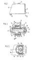
- FIG. 1 shows a headlamp in a greatly simplified representation in the front view
- FIG. 2 shows the headlamp in sections as a section along line II-II in FIG. 1
- FIG. 3 shows the headlamp in sections as a section along line III-III in FIG. 2.
- a headlight for motor vehicles shown in Figure 1 has a housing 10 made of plastic, the front of which is covered with a lens 11, wherein a reflector (not shown) with a light source is arranged in the housing 10.
- the housing 10 serves as a holder for fastening the headlamp to a body part, for example at the front end 12 of the motor vehicle.
- the housing 10 can be fixed on the front end 12 via a plurality of bearing points 13 arranged on its outer walls in the exemplary embodiment. At each bearing point 13 an outwardly projecting receptacle 14 is formed on the outer walls, into which a socket-like holding element 16 made of plastic can be inserted, via which the housing 10 comes to rest against the front end 12 approximately in the direction of the longitudinal axis 17 of the motor vehicle.
- the holding element 16 can be inserted into the receptacle 14 in the direction of its longitudinal axis parallel to the longitudinal axis 17 of the motor vehicle.
- the holding element 16 has a section 19 lying inside the receptacle 14 with two flattened regions 21 lying radially opposite one another and perpendicular to these two radially opposite circular cylindrical regions 22.
- the arcuate regions 22 are each provided on their outer sides with straight teeth 23 stepped along the longitudinal axis 17 and are designed to be radially elastically deformable.
- the holding element 16 has a cylindrical section 24 towards the front end 12.
- the holding element 16 is provided with a through opening 26 which is essentially rectangular in cross section.
- a radially elastically pivotable hook 27 is formed on the free end of section 24.
- the receptacle 14 is U-shaped in section transverse to the longitudinal axis 17, the legs pointing away from the housing 10 radially to the longitudinal axis 17.
- the legs of the receptacle 14 are formed by two boundary walls 28, 29, each of which has a straight toothing 31 corresponding to the toothing 23 on the holding element 16 on their opposite surfaces.
- the receptacle 14 is open between the outwardly facing ends of the boundary walls 28, 29.
- the receptacle can also be designed in cross section in the form of an elongated hole, the diameter of the receptacle 14 in a central section parallel to the two walls 28, 29 being greater than its diameter in a central section perpendicular to the walls 28, 29.
- the receptacle 14 has towards the front end 12 an end wall 32 arranged transversely to the longitudinal axis 17 and having a bore 33.
- the holding element 16 can be inserted into the receptacle 14 in the direction of its longitudinal axis 17 in a rotational position, in which its flattened regions 21 face the walls 28, 29.
- the cylindrical section 24 passes through the bore 33 in the end wall 32 of the receptacle to the front end 12, so that the holding element 16 is rotatably held.
- the hook 27 springs outwards, so that the holding element 16 is held captively in the receptacle 14.
- the holding element 16 By rotating in the fastening direction about its longitudinal axis 17, the holding element 16 can be axially fixed in the receptacle 14 by the toothing 23 of the holding element 16 coming into engagement with the toothing 31 of the receptacle 14.
- the diameter of the receptacle 14 in the region of its toothing 31 is slightly smaller than the diameter of the holding element 16 in the region of its toothing 23, so that the holding element 16 and / or the receptacle is radially elastically deformed when it is fixed and is clamped and held in the receptacle 14 unintentional loosening of the holding element is prevented during the further assembly of the headlight.
- the rotational movement of the holding element 16 is so limited when it is fixed by a molded on the receptacle 14, pointing radially inward and serving as a stop, that the holding element 16 cannot be rotated by more than 90 °.
- a screw 36 is inserted as a fastening element, which is supported with its head 37 on the end face of the holding element 16, with its threaded portion passes through an opening 38 in the front end 12 and can be fastened to the front end by means of a nut 39.
- the diameter of the screw 36 is significantly smaller than the clear width of the through opening 26.
- the headlamp When the headlamp is attached to the front end 12, the headlamp is initially aligned in the direction of the longitudinal axis 17 of the motor vehicle by correctly aligning the lens 11, for example with respect to the shape of the outer surface of the body or the beam direction of the light emitted by the headlamp.
- the holding elements 16 In this position of the headlamp, the holding elements 16 are fixed so that the headlamp rests on the holding elements on the front end 12. The finer the teeth 23 and 31 are divided, the more precisely the headlight can be aligned.
- the headlight is held in this position on the front end 12, but can still be adjusted transversely to the longitudinal axes 18 of the holding elements 16, since the screws 36 pass through the holding elements 16 with a large radial play in order to adjust the height and side of the headlight to enable. If the height and side adjustment of the headlamp has also been carried out, the nuts 39 are tightened to the end and the headlamp is thus securely held on the front end 12.
- the screws 36 need to be loosened, but not the holding elements 16 which remain in their correct positions in the receptacles 14.
- the headlight is reinstalled, only the height and side adjustment then need to be carried out again, but not the headlight adjustment in the direction of the longitudinal axis 17.
- the receptacle can also be arranged on the front end, the housing of the headlight coming into contact with the holding element and the screw passing through the holding element being able to be fixed on the housing by means of a nut.
- the headlamp can also be designed as an insert headlamp which can be fixed on the front end via a support frame serving as a holder, the receptacles then being arranged on the support frame.
Landscapes
- Engineering & Computer Science (AREA)
- Mechanical Engineering (AREA)
- Lighting Device Outwards From Vehicle And Optical Signal (AREA)
Applications Claiming Priority (2)
| Application Number | Priority Date | Filing Date | Title |
|---|---|---|---|
| DE4017701A DE4017701A1 (de) | 1990-06-01 | 1990-06-01 | Scheinwerfer fuer kraftfahrzeuge |
| DE4017701 | 1990-06-01 |
Publications (2)
| Publication Number | Publication Date |
|---|---|
| EP0459187A1 true EP0459187A1 (fr) | 1991-12-04 |
| EP0459187B1 EP0459187B1 (fr) | 1994-12-14 |
Family
ID=6407639
Family Applications (1)
| Application Number | Title | Priority Date | Filing Date |
|---|---|---|---|
| EP91107451A Expired - Lifetime EP0459187B1 (fr) | 1990-06-01 | 1991-05-08 | Phare pour véhicule |
Country Status (3)
| Country | Link |
|---|---|
| US (1) | US5122934A (fr) |
| EP (1) | EP0459187B1 (fr) |
| DE (2) | DE4017701A1 (fr) |
Cited By (3)
| Publication number | Priority date | Publication date | Assignee | Title |
|---|---|---|---|---|
| EP0679553A1 (fr) * | 1994-04-28 | 1995-11-02 | Valeo Vision | Ensemble pour la fixation ajustable selon trois dimensions d'un dispositif d'éclairage et/ou de signalisation de véhicule automobile |
| US9150145B2 (en) | 2014-02-07 | 2015-10-06 | Volkswagen Ag | Vehicle headlight assembly with self-adjusting fasteners |
| WO2017078643A1 (fr) * | 2015-11-04 | 2017-05-11 | Tofas Turk Otomobil Fabrikasi Anonim Sirketi | Ensemble douille à blocage de rotation |
Families Citing this family (7)
| Publication number | Priority date | Publication date | Assignee | Title |
|---|---|---|---|---|
| DE19636029C1 (de) * | 1996-09-05 | 1998-02-12 | Bosch Gmbh Robert | Frontleuchteneinheit für ein Kraftfahrzeug |
| DE19650864B4 (de) * | 1996-12-07 | 2006-10-19 | Automotive Lighting Reutlingen Gmbh | Anordnung zur Befestigung einer Beleuchtungseinrichtung an einem Fahrzeugteil |
| CA2303808C (fr) | 1997-10-24 | 2007-07-10 | Decoma International Inc. | Ensemble de module d'extremite prevu pour etre installe sur un vehicule et procede de fabrication de ce dernier |
| US6282769B1 (en) | 1998-07-15 | 2001-09-04 | Cosma International Inc. | Motor vehicle end module assembly |
| DE10315140A1 (de) | 2003-04-03 | 2004-10-28 | Dr.Ing.H.C. F. Porsche Ag | Ausrichtvorrichtung für einen Scheinwerfer |
| DE102005037816A1 (de) | 2005-08-08 | 2007-02-22 | Hbpo Gmbh | Vorrichtung zur justierbaren Befestigung eines Scheinwerfers |
| DE102011000360A1 (de) * | 2011-01-27 | 2012-08-02 | Hella Kgaa Hueck & Co. | Beleuchtungsvorrichtung für Fahrzeuge und Befestigungsverfahren für die Beleuchtungsvorrichtung |
Citations (2)
| Publication number | Priority date | Publication date | Assignee | Title |
|---|---|---|---|---|
| DE3540724C1 (de) * | 1985-11-16 | 1986-12-04 | Audi AG, 8070 Ingolstadt | Einstelleinrichtung für ein Scheinwerfergehäuse an einem Kraftfahrzeug |
| EP0239440A1 (fr) * | 1986-02-24 | 1987-09-30 | Valeo Vision | Dispositif de fixation réglable, notamment pour projecteur de véhicule |
Family Cites Families (4)
| Publication number | Priority date | Publication date | Assignee | Title |
|---|---|---|---|---|
| US4356539A (en) * | 1979-10-16 | 1982-10-26 | General Electric Company | Vehicle headlamp having an integral buggy spring mounting assembly |
| US4796165A (en) * | 1988-03-18 | 1989-01-03 | Chrysler Motors Corporation | Vehicle tail light construction |
| DE3902229A1 (de) * | 1989-01-26 | 1990-08-02 | Opel Adam Ag | Scheinwerfer |
| US4994942A (en) * | 1990-08-26 | 1991-02-19 | Chrysler Corporation | Vehicle tail light construction |
-
1990
- 1990-06-01 DE DE4017701A patent/DE4017701A1/de not_active Withdrawn
-
1991
- 1991-04-17 US US07/686,701 patent/US5122934A/en not_active Expired - Fee Related
- 1991-05-08 EP EP91107451A patent/EP0459187B1/fr not_active Expired - Lifetime
- 1991-05-08 DE DE59103849T patent/DE59103849D1/de not_active Expired - Fee Related
Patent Citations (2)
| Publication number | Priority date | Publication date | Assignee | Title |
|---|---|---|---|---|
| DE3540724C1 (de) * | 1985-11-16 | 1986-12-04 | Audi AG, 8070 Ingolstadt | Einstelleinrichtung für ein Scheinwerfergehäuse an einem Kraftfahrzeug |
| EP0239440A1 (fr) * | 1986-02-24 | 1987-09-30 | Valeo Vision | Dispositif de fixation réglable, notamment pour projecteur de véhicule |
Cited By (4)
| Publication number | Priority date | Publication date | Assignee | Title |
|---|---|---|---|---|
| EP0679553A1 (fr) * | 1994-04-28 | 1995-11-02 | Valeo Vision | Ensemble pour la fixation ajustable selon trois dimensions d'un dispositif d'éclairage et/ou de signalisation de véhicule automobile |
| FR2719269A1 (fr) * | 1994-04-28 | 1995-11-03 | Valeo Vision | Ensemble pour la fixation ajustable selon trois dimensions d'un dispositif d'éclairage et/ou de signalisation de véhicule automobile. |
| US9150145B2 (en) | 2014-02-07 | 2015-10-06 | Volkswagen Ag | Vehicle headlight assembly with self-adjusting fasteners |
| WO2017078643A1 (fr) * | 2015-11-04 | 2017-05-11 | Tofas Turk Otomobil Fabrikasi Anonim Sirketi | Ensemble douille à blocage de rotation |
Also Published As
| Publication number | Publication date |
|---|---|
| DE4017701A1 (de) | 1991-12-05 |
| EP0459187B1 (fr) | 1994-12-14 |
| US5122934A (en) | 1992-06-16 |
| DE59103849D1 (de) | 1995-01-26 |
Similar Documents
| Publication | Publication Date | Title |
|---|---|---|
| DE102012011848A1 (de) | Befestigungsanordnung | |
| WO1999013525A1 (fr) | Dispositif de fixation d'un capteur de distance sur un vehicule automobile | |
| DE102005044064A1 (de) | Schraubenverbindung mit Toleranzausgleich | |
| EP0459187A1 (fr) | Phare pour véhicule | |
| DE4237674A1 (de) | Rohrschelle | |
| EP0340454B1 (fr) | Phare de véhicule | |
| DE10009978A1 (de) | Vorrichtung zur Befestigung einer Fahrzeugantenne | |
| EP0551149B1 (fr) | Point d'attache pour la fixation d'une pièce de montage à un barre de support | |
| DE4228889A1 (de) | Scheinwerfer für Fahrzeuge | |
| DE10334050B4 (de) | Vorrichtung zur Befestigung eines Anschlussfittings an einem Gegenstand, insbesondere an einer Wand | |
| EP0978416B1 (fr) | Dispositif pour la fixation réglable d'un phare | |
| DE102007049513B4 (de) | Zirkel | |
| DE19741421C1 (de) | Befestigungselement für eine Kraftfahrzeugleuchte | |
| DE60014565T2 (de) | Exzentrisch einstellbare Mutter | |
| DE19537815B4 (de) | Scheinwerfer für Fahrzeuge | |
| DE4340114A1 (de) | Einstellbarer Puffer | |
| DE10309087A1 (de) | Befestigungseinrichtung für Kraftfahrzeug-Scheinwerfer | |
| DE10009589B4 (de) | Befestigungssystem für eine Lichtquelle an einem Reflektor eines Scheinwerfers | |
| EP0860617B1 (fr) | Vis comportant une tête en profile d'un marteau pour la fixation au plafond | |
| DE10104757B4 (de) | Befestigungsvorrichtung zur verstellbaren Befestigung eines Fahrzeugteils | |
| DE102005016972A1 (de) | Befestigungs- und Einstellvorrichtung zum lösbaren Befestigen zweier Bauteile aneinander | |
| DE4340306C1 (de) | Ausrichtvorrichtung zur Einpassung eines Kraftfahrzeugscheinwerfers in einen Karosserieausschnitt | |
| DE19722965C1 (de) | Haltevorrichtung für ein verschiebbares Abgriffselement eines Potentiometers einer elektrischen Verstelleinrichtung zur Verstellung eines Reflektors eines Fahrzeugscheinwerfers | |
| DE19859803A1 (de) | Polklemme zur Befestigung wenigstens eines Kabels an einem Pol eines Akkumulators | |
| DE2616912A1 (de) | Vorrichtung zum befestigen des ablenksystems auf dem hals einer elektronenstrahlroehre |
Legal Events
| Date | Code | Title | Description |
|---|---|---|---|
| PUAI | Public reference made under article 153(3) epc to a published international application that has entered the european phase |
Free format text: ORIGINAL CODE: 0009012 |
|
| AK | Designated contracting states |
Kind code of ref document: A1 Designated state(s): DE FR GB |
|
| RAP3 | Party data changed (applicant data changed or rights of an application transferred) |
Owner name: ROBERT BOSCH GMBH |
|
| 17P | Request for examination filed |
Effective date: 19920529 |
|
| 17Q | First examination report despatched |
Effective date: 19931104 |
|
| GRAA | (expected) grant |
Free format text: ORIGINAL CODE: 0009210 |
|
| AK | Designated contracting states |
Kind code of ref document: B1 Designated state(s): DE FR GB |
|
| ET | Fr: translation filed | ||
| REF | Corresponds to: |
Ref document number: 59103849 Country of ref document: DE Date of ref document: 19950126 |
|
| GBT | Gb: translation of ep patent filed (gb section 77(6)(a)/1977) |
Effective date: 19950217 |
|
| PLBE | No opposition filed within time limit |
Free format text: ORIGINAL CODE: 0009261 |
|
| STAA | Information on the status of an ep patent application or granted ep patent |
Free format text: STATUS: NO OPPOSITION FILED WITHIN TIME LIMIT |
|
| 26N | No opposition filed | ||
| REG | Reference to a national code |
Ref country code: GB Ref legal event code: 746 Effective date: 19960612 |
|
| REG | Reference to a national code |
Ref country code: FR Ref legal event code: D9 Free format text: CORRECTION |
|
| PGFP | Annual fee paid to national office [announced via postgrant information from national office to epo] |
Ref country code: GB Payment date: 19970422 Year of fee payment: 7 |
|
| PGFP | Annual fee paid to national office [announced via postgrant information from national office to epo] |
Ref country code: FR Payment date: 19970523 Year of fee payment: 7 |
|
| PG25 | Lapsed in a contracting state [announced via postgrant information from national office to epo] |
Ref country code: GB Free format text: LAPSE BECAUSE OF NON-PAYMENT OF DUE FEES Effective date: 19980508 |
|
| PG25 | Lapsed in a contracting state [announced via postgrant information from national office to epo] |
Ref country code: FR Free format text: LAPSE BECAUSE OF NON-PAYMENT OF DUE FEES Effective date: 19980531 |
|
| GBPC | Gb: european patent ceased through non-payment of renewal fee |
Effective date: 19980508 |
|
| REG | Reference to a national code |
Ref country code: FR Ref legal event code: ST |
|
| PGFP | Annual fee paid to national office [announced via postgrant information from national office to epo] |
Ref country code: DE Payment date: 19991230 Year of fee payment: 10 |
|
| PG25 | Lapsed in a contracting state [announced via postgrant information from national office to epo] |
Ref country code: DE Free format text: LAPSE BECAUSE OF NON-PAYMENT OF DUE FEES Effective date: 20020301 |