EP0458440A1 - Adjustable lumbar support mechanism for a vehicular seat - Google Patents
Adjustable lumbar support mechanism for a vehicular seat Download PDFInfo
- Publication number
- EP0458440A1 EP0458440A1 EP91301670A EP91301670A EP0458440A1 EP 0458440 A1 EP0458440 A1 EP 0458440A1 EP 91301670 A EP91301670 A EP 91301670A EP 91301670 A EP91301670 A EP 91301670A EP 0458440 A1 EP0458440 A1 EP 0458440A1
- Authority
- EP
- European Patent Office
- Prior art keywords
- lumbar
- assembly
- backrest
- screw shaft
- adjustor
- Prior art date
- Legal status (The legal status is an assumption and is not a legal conclusion. Google has not performed a legal analysis and makes no representation as to the accuracy of the status listed.)
- Withdrawn
Links
- 230000007246 mechanism Effects 0.000 title abstract description 4
- 238000006073 displacement reaction Methods 0.000 claims description 3
- 239000012858 resilient material Substances 0.000 claims description 3
- 210000004705 lumbosacral region Anatomy 0.000 abstract description 5
- 230000004075 alteration Effects 0.000 abstract 1
- 230000000712 assembly Effects 0.000 description 6
- 238000000429 assembly Methods 0.000 description 6
- 238000000034 method Methods 0.000 description 4
- 125000006850 spacer group Chemical group 0.000 description 3
- 238000004519 manufacturing process Methods 0.000 description 2
- 230000008569 process Effects 0.000 description 2
- 230000037237 body shape Effects 0.000 description 1
- 230000003247 decreasing effect Effects 0.000 description 1
- 230000002950 deficient Effects 0.000 description 1
- 230000007613 environmental effect Effects 0.000 description 1
- 230000006872 improvement Effects 0.000 description 1
- 239000000463 material Substances 0.000 description 1
- 230000004048 modification Effects 0.000 description 1
- 238000012986 modification Methods 0.000 description 1
- 230000009467 reduction Effects 0.000 description 1
- 230000004044 response Effects 0.000 description 1
Images


Classifications
-
- B—PERFORMING OPERATIONS; TRANSPORTING
- B60—VEHICLES IN GENERAL
- B60N—SEATS SPECIALLY ADAPTED FOR VEHICLES; VEHICLE PASSENGER ACCOMMODATION NOT OTHERWISE PROVIDED FOR
- B60N2/00—Seats specially adapted for vehicles; Arrangement or mounting of seats in vehicles
- B60N2/64—Back-rests or cushions
- B60N2/66—Lumbar supports
-
- A—HUMAN NECESSITIES
- A47—FURNITURE; DOMESTIC ARTICLES OR APPLIANCES; COFFEE MILLS; SPICE MILLS; SUCTION CLEANERS IN GENERAL
- A47C—CHAIRS; SOFAS; BEDS
- A47C7/00—Parts, details, or accessories of chairs or stools
- A47C7/36—Supports for the head or the back
- A47C7/40—Supports for the head or the back for the back
- A47C7/46—Supports for the head or the back for the back with special, e.g. adjustable, lumbar region support profile; "Ackerblom" profile chairs
- A47C7/462—Supports for the head or the back for the back with special, e.g. adjustable, lumbar region support profile; "Ackerblom" profile chairs adjustable by mechanical means
-
- B—PERFORMING OPERATIONS; TRANSPORTING
- B60—VEHICLES IN GENERAL
- B60N—SEATS SPECIALLY ADAPTED FOR VEHICLES; VEHICLE PASSENGER ACCOMMODATION NOT OTHERWISE PROVIDED FOR
- B60N2/00—Seats specially adapted for vehicles; Arrangement or mounting of seats in vehicles
- B60N2/64—Back-rests or cushions
- B60N2/66—Lumbar supports
- B60N2/666—Lumbar supports vertically adjustable
Definitions
- the subject invention relates to a mechanical adjustable lumbar support assembly disposed in a vehicle seat backrest for altering the contour of the backrest to provide adjustable lumbar support.
- Seats and more particularly vehicular seats, frequently include an adjustable support assembly for a passenger's back.
- the adjustable back support assembly is disposed inside the seat and positioned to apply pressure to the lower lumbar region.
- the lumbar support assembly is made adjustable to accommodate passengers of different body shapes and different support preferences.
- the prior art adjustable lumbar support assemblies are deficient in that connection of the lumbar adjustor means and the support means requires a labor-intensive operation which is both time consuming and expensive. Special connectors are fabricated to unite the two elements, and tools are required for proper assembly. It will be appreciated that when used in mass production vehicular seats, extremely large quantities of adjustable lumbar support assemblies must be manufactured. And therefore, when considered together, the additional time and expense required to connect the lumbar adjustor means and the support means becomes significant and costly.
- the subject invention provides an adjustable lumbar support assembly of the type disposed within a seat backrest for altering the contour of the backrest to provide adjustable lumbar support.
- the assembly comprises a lumbar adjustor means adapted for inclusion within a seat backrest for incrementally adjusting the contour of the backrest to provide variable lumbar support.
- a support means is provided for attachment to the backrest for supporting the lumbar adjustor means on the backrest.
- the invention is characterized by a mechanical locking means for forcibly receiving the lumbar adjustor means on the support means as the lumbar adjustor means is moved into a mechanically interlocked position with the support means to allow rapid assembly of the lumbar adjustor means and the support means as an operational unit to be installed within a seat backrest.
- the mechanical locking means of the subject invention provides a unique and advantageous connection of the lumbar adjustor means to the support means.
- the invention provides an automatic connection of the lumbar adjustor means and the support means simply upon forced movement of the lumbar adjustor means toward a mechanical locked position with the support means so that the assembly may be rapidly assembled and subsequently disposed within a seat backrest.
- the subject invention provides for a significant reduction in the time required to assemble the elements and hence provides significant savings in cost.
- an adjustable lumbar support assembly is generally shown at 20.
- a seat assembly is generally indicated at 22 and includes a backrest portion 24 and a seat portion 26.
- a lumbar region of the backrest 24 is generally represented by the bracketed area 28, as shown in Figure 1.
- the lumbar support assembly 20 is disposed within the backrest 24 for altering the contour of the backrest 24 to provide adjustable lumbar support within the lumbar region 28.
- the lumbar support assembly 20 includes a lumbar adjustor means, generally indicated at 30, which is enclosed within the seat backrest 24 for incrementally adjusting the contour of the backrest 24 to provide variable lumbar support.
- the lumbar adjustor means 30 comprises the structure moving within the backrest 24 to physically alter the contour of the backrest 24 inwardly or outwardly such that pressure is applied in various increments to the lumbar region of an occupant in the seat assembly 22.
- a support means, generally indicated at 32 is provided for attachment to the backrest 24 for supporting the lumbar adjustor means 30 on the backrest 24. Therefore, the support means 32 provides an interface between the lumbar adjustor means 30 and the backrest 24 to support the lumbar adjustor means 30 for movement within the backrest 24.
- the improvement of the subject invention comprises a mechanical locking means, generally indicated at 34, for forcibly receiving the lumbar adjustor means 30 on the support means 32 as the lumbar adjustor means 30 is moved into a mechanical interlocked position with the support means 32 to allow rapid assembly of the lumbar adjustor means 30 and the support means 32 as an operational unit to be installed within the backrest 24. That is, the mechanical locking means 34 provides automatic fastening and connecting of the lumbar adjustor means 30 and the support means 32 in response to a forced movement of the lumbar adjustor means 30 into a mechanically interlocked position on the support means 32.
- the mechanical locking means 34 allows rapid and simple connection of the elements of the subject invention without the need for additional tools or time consuming manufacturing assembly operations.
- the lumbar adjustor means 30 includes an elongated screw shaft 36 having a generally horizontal longitudinal axis.
- the screw shaft 36 is supported on the mechanical locking means 34 for rotation about its longitudinal axis.
- the screw shaft 36 includes a first set of external thread patterns 38 wound in the right hand direction. That is, the first set of threads 38 are male thread convolutions having a thread propagation tending to axially advance the screw shaft 36 when rotated in a clockwise direction about the longitudinal axis.
- the screw shaft 36 also includes a second set of external thread patterns 40 which are spaced axially from the first threads 38.
- the second threads 40 are male thread convolutions having a left hand propagation causing retraction of the screw shaft 36 when rotated in a clockwise direction about its longitudinal axis.
- a first nut-like travelling member 42 is disposed in operative engagement with the first threads 38 and supported for non-rotating linear movement along the screw shaft 36.
- a second nut-like traveling member 44 is operatively engaged with the second threads 40 and also supported for non-rotating linear movement along the screw shaft 36.
- the first 42 and second 44 travelling members have a generally cubical shape with an internally threaded bore extending centrally through each member.
- the first travelling member 42 includes a pair of pintles 46 extending therefrom and disposed on opposite sides of the longitudinal axis of the screw shaft 36.
- the pintles 46 extend from the top and bottom surfaces of the cubical first travelling member 42.
- the second travelling member 44 includes a pair of pintles 48 extending therefrom and disposed on opposite sides of the longitudinal axis.
- a first link 50 is pivotally connected to the first travelling member 42.
- the first link 50 has a generally U-shaped cross section comprised of upper and lower parallel struts 52 interconnected by an integral bridge 54.
- the struts 52 are slightly longer than the bridge 54 such that the distal ends are flexible and resilient when the first link 50 is fabricated from a resilient material such as plastic.
- a spacer 56 is disposed over the pintle 46 and between one of the struts 52 and the first travelling member 42, as shown in Figure 5.
- a second link 58 is pivotally connected to the second travelling member 44.
- the second link 58 is identical to the first link 50 and includes upper and lower struts 60 maintained spaced and parallel by a connecting bridge 62.
- a pair of aligned holes in the struts 60 pivotally receive the pintles 48 of the second travelling member 44 for establishing the pivotal connection between the two elements.
- a spacer 64 is disposed on one of the pintles 48 and positioned between the second travelling member 44 and one of the struts 60, as shown in Figure 5.
- the first 50 and second 58 links are pivotally connected to one another at a displaceable joint 66 which is spaced from the first 42 and second 44 travelling members. More particularly, the displaceable joint 66 resembles a cross member to which each of the first 50 and second 58 links are connected in overlapping fashion. As best shown in Figures 2 and 5, the first 50 and second 58 links are interleaved with one another at the displaceable joint 66 and, for this reason, the spacers 56, 64 are employed on opposite sides of the respective travelling members 42, 44 to maintain the first 50 and second 58 links in a parallel orientation.
- the lumbar adjustor means 30 further includes a substantially rigid pressure applicator 68 for forcibly altering the contour of the backrest 24.
- the pressure applicator 68 comprises a paddle-shaped member having two sheet-like planar jutting surfaces 70 spaced on opposite sides of a sheet-like planar middle recessed surface 72. Extending rearwardly of the recessed surface 72 are a pair of spaced tabs 74.
- the tabs 74 extend in generally parallel vertical planes and each include a hole 76, as shown in Figure 6.
- the holes 76 of each of the tabs 74 are aligned along a horizontal axis.
- the displaceable joint 66 comprises a universal spider-type joint. That is, two vertically spaced displacement pintles 78 of the displaceable joint 66 engage and pivotally connect the first 50 and second 58 links while two horizontally spaced applicator pintles 80 engage and pivotally support the holes 76 of the tabs 74 such that the pressure applicator 68 is universally pivotally connected to the first 50 and second 58 links.
- the tabs 74 of the pressure applicator 68 are sufficiently flexible and resilient so that the displaceable joint 66 can be inserted into the tab holes 76 without the aid of special tools or disassembly of the elements.
- the first 50 and second 58 links are fabricated from a resilient material which is sufficiently flexible to allow connection to the displaceable joint 66 and the respective first 42 and second 44 travelling members without special assembly techniques.
- the resilient tabs 74 and links 50, 58 cooperate with the mechanical locking means 34 to allow the entire assembly of the lumbar adjustor means 30 and the Support means 32 to be connected together without the requirement of special assembly techniques.
- the mechanical locking means 34 includes three resilient prong members 82 extending from a fixed connection on the support means 32, as shown in Figure 6.
- the mechanical locking means 34 also includes a socket 84 likewise extending from a fixed connection on the support means 32.
- the prongs 82 and socket 84 are horizontally aligned on the support means 32 and extend outwardly therefrom in parallel vertical planes.
- the socket 84 is adapted to receive and rotatably support a terminal end 86 of the screw shaft 36.
- the prongs 82 on the other hand, forcibly receive the screw shaft 36 at spaced locations and support the screw shaft 36 for rotation about its longitudinal axis.
- the prongs 82 have a circular inner bearing surface 88 matingly shaped to receive the screw shaft 36. Retaining tips 90 flex outwardly as the screw shaft 36 is forcibly moved toward the inner bearing surface 88, as shown in Figure 8. Once the screw shaft 36 is moved contiguous the inner bearing surface 88, the retaining tips 90 flex back inwardly and support the screw shaft 36 for rotation, as shown in Figure 9.
- the first 42 and second 44 travelling members are first assembled onto the respective first 38 and second 40 threads, with the respective pintles 46, 48 extending in vertical directions.
- the first 50 and second 58 links are then forcibly received on the respective pintles 46, 48 of the first 42 and second 44 travelling members.
- the first 50 and second 58 links are then forcibly received on the displacement pintles 78 of the displaceable joint 66.
- the applicator pintles 80 are next forcibly received in the holes 76 of the tabs 74 of the pressure applicator 68.
- the terminal end 86 of the screw shaft 36 is inserted into the socket 84 and the screw shaft 36 is moved toward the prongs 82 such that the screw shaft 36 is forcibly received in the prongs 82 and supported therein for rotation.
- the support means 32 comprises a plate-like member having a fastening lip 92 disposed at one end thereof and a pair of spaced openings 94 at the other end thereof.
- An elongated groove 96 extends horizontally into the support means 32, between the two openings 94, through which the screw shaft 36 may pass.
- a backset plate 98 is integrally disposed intermediate the fastening lip 92 and the openings 94 and supports the prongs 82 and socket 84.
- the backrest 24 is shown including structural frame members 100 each having an oval tubular cross section.
- the frame members 100 on the right side of the backrest 24 include an inwardly extending mounting bracket 102.
- a vertically extending slot adapted to receive the fastening lip 92 of the support means 32.
- Extending inwardly from the left side frame members 100 is a similar mounting bracket 104.
- the mounting bracket 104 includes a pair of vertically spaced holes adapted to align with the openings 94 in the support means 32. Therefore, when the support means 32 is mounted to the mounting brackets 102, 104, fasteners of some conventional type are positioned through the openings 94 and the corresponding holes in the mounting bracket 104 to fixedly support the assembly 20 in the backrest 24.
- a rotary input comprising a hand crank 106 is provided for rotating the screw shaft 36.
- a rotation multiplier means 108, 108' is provided in association with the hand crank 106 for rotating the screw shaft 36 in the mechanical locking means 34 at a higher rotational velocity than the hand crank 106.
- Two alternative embodiments of the rotation multiplier means 108, 108' are shown in Figures 1 and 2.
- the rotation multiplier means 108 is shown with a belt pulley 110 operatively engaged to the hand crank 106 and disposed for operative engagement with the screw shaft 36.
- the rotation multiplier means 108' is shown with the hand crank 106 having an internal annular gear set 112 disposed in matingly engagement with a pinion gear 114 extending integrally from the screw shaft 36.
- the hand crank 106 is supported for rotation on the side of the backrest 24 in a conventional manner.
- FIG. 10 an alternative, or modified, version of the support means 32' is shown including a vertical adjustment means, generally indicated at 116, for adjusting the lumbar adjustor means 30 vertically within the backrest 24.
- a tubular backrest frame 118 is shown including a horizontal upper cross piece 120 and a vertically spaced lower cross piece 122.
- each of the vertical guide members 124 include a tongue disposed at the lower end thereof and adapted to be received in a slot 126 in the lower cross piece 122.
- a resilient spring clip 128 is integrally formed at the upper end of each vertical guide member 124.
- the upper cross piece 120 is shaped and so disposed as to be forcibly received in the clip 128 and fixedly supported therein in a mechanically interlocked position. Therefore, the vertical guide members 124 are supported between the upper 120 and lower 122 cross pieces of the backrest frame 118.
- a spanner 130 is fixedly connected to and extends horizontally between each of the vertical guide members 124, midway between the upper 120 and lower 122 cross pieces.
- a plate-like arm 132 is disposed in a generally horizontal plane and extends forwardly from the spanner 130.
- the support means 32' further includes a carriage 134 which is moveably connected to the vertical guide members 124, as shown in Figure 10.
- the carriage 134 supports the mechanical locking means 34 and, thus, the screw shaft 36, links 50, 58 and the pressure applicator 68.
- the pressure applicator 68 is likewise adjustable vertically within the backrest to provide lumbar support at different vertical positions.
- a worm mechanism operatively interconnects the vertical guide members 124 and the carriage 134, and more specifically the spanner 130 and the carriage 134.
- the worm mechanism 136 includes a nut 138 fixedly attached to the carriage 134 and a screw element 140 rotatably supported on the arm 132 of the spanner 130. Therefore, as the screw element 140 rotates, it displaces the nut 138, and hence the carriage 134, linearly along the vertical guide members 124.
- the screw element 140 is connected to a flexible motion transmitting core element supported for rotation within a conduit 142.
- the conduit 142, and hence the core element, extend from the arm 132 to a remote rotary actuator 144.
- the remote rotary actuator 144 is coaxially located with the hand crank 106 to provide a compact assembly on the exterior of the backrest 24. Because the carriage 134, and hence the screw shaft 136, are moveably disposed within the backrest, the screw shaft 36 must also be connected to the hand crank 106 through a flexible motion transmitting assembly as indicated at 146.
- the subject invention is particularly advantageous when mass produced for high volume sale due to the decreased assembly time required to operatively connect the various moving elements. As each of the connected elements are snap-fit together, special tools are not required. Further, as best shown in Figure 3, the subject invention has a very thin profile and therefore nests neatly within the backrest 24. Further, because many of the elements are fabricated from an elastomeric polymeric material, additional weight savings over prior art assemblies can be realized.
Landscapes
- Engineering & Computer Science (AREA)
- Mechanical Engineering (AREA)
- Aviation & Aerospace Engineering (AREA)
- Transportation (AREA)
- Chair Legs, Seat Parts, And Backrests (AREA)
Abstract
An adjustable lumbar support mechanism (20) includes a screw shaft (36) having spaced apart right hand (38) and left hand (40) thread convolutions. A traveling nut (42, 44) is disposed in coacting engagement with each of the right hand (38) and left hand (40) threads for linear movement in opposite directions along the screw shaft (36). A pair of links (50, 58) are pivotally attached to each other and at opposite ends to each of the traveling nuts (42, 44) such that movement of the nuts (42, 44) along the screw shaft (36) laterally displaces the links (50, 58). A pressure applicator (68) is attached to the links (50, 58) by a universal joint connection (66). The screw shaft (36) extends outwardly from the seat (22) to an external hand crank (106). The assembly is disposed in a vehicular seat (22) such that movement of the pressure applicator (68) causes an alteration in the contour of the lumbar region (28) of the seat (22) thereby providing adjustable lumbar support.
Description
- The subject invention relates to a mechanical adjustable lumbar support assembly disposed in a vehicle seat backrest for altering the contour of the backrest to provide adjustable lumbar support.
- Seats, and more particularly vehicular seats, frequently include an adjustable support assembly for a passenger's back. The adjustable back support assembly is disposed inside the seat and positioned to apply pressure to the lower lumbar region. The lumbar support assembly is made adjustable to accommodate passengers of different body shapes and different support preferences.
- One such prior art adjustable lumbar support assembly is shown in the United States Patent Number 4,295,681 to Gregory, issued October 20, 1981. Gregory discloses a manually adjustable lumbar adjustor means disposed within a seat backrest for incrementally adjusting the contour of the backrest to provide a variable lumbar support. The lumbar adjustor means is supported in the backrest by a support means. Manual actuation of an exterior adjustment knob provides incremental adjustment of the backrest contour. A complicated assembly process is required to connect the lumbar adjustor means and the support means.
- Two prior art adjustable lumbar support assemblies structurally similar to Gregory are shown in United States Patent Number 4,678,230 to Winkle, issued July 7, 1989 and United States Patent Number 4,657,304 to Heesch et al, issued April 14, 1987. These prior art assemblies disclose a lumbar adjustor means disposed within a seat backrest for incrementally adjusting the contour of the backrest to provide variable lumbar support. A support means is provided for attachment to the backrest for supporting the lumbar adjustor means within on the backrest. As with Gregory, these assemblies also require a complicated assembly process to connect the lumbar adjustor means and the support means.
- Therefore, the prior art adjustable lumbar support assemblies are deficient in that connection of the lumbar adjustor means and the support means requires a labor-intensive operation which is both time consuming and expensive. Special connectors are fabricated to unite the two elements, and tools are required for proper assembly. It will be appreciated that when used in mass production vehicular seats, extremely large quantities of adjustable lumbar support assemblies must be manufactured. And therefore, when considered together, the additional time and expense required to connect the lumbar adjustor means and the support means becomes significant and costly.
- The subject invention provides an adjustable lumbar support assembly of the type disposed within a seat backrest for altering the contour of the backrest to provide adjustable lumbar support. The assembly comprises a lumbar adjustor means adapted for inclusion within a seat backrest for incrementally adjusting the contour of the backrest to provide variable lumbar support. A support means is provided for attachment to the backrest for supporting the lumbar adjustor means on the backrest. The invention is characterized by a mechanical locking means for forcibly receiving the lumbar adjustor means on the support means as the lumbar adjustor means is moved into a mechanically interlocked position with the support means to allow rapid assembly of the lumbar adjustor means and the support means as an operational unit to be installed within a seat backrest.
- The mechanical locking means of the subject invention provides a unique and advantageous connection of the lumbar adjustor means to the support means. The invention provides an automatic connection of the lumbar adjustor means and the support means simply upon forced movement of the lumbar adjustor means toward a mechanical locked position with the support means so that the assembly may be rapidly assembled and subsequently disposed within a seat backrest. The subject invention provides for a significant reduction in the time required to assemble the elements and hence provides significant savings in cost.
- Other advantages of the present invention will be readily appreciated as the same becomes better understood by reference to the following detailed description when considered in connection with the accompanying drawings wherein:
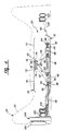
- Figure 1 is an environmental view of the subject invention shown disposed for operation within a vehicular seat;
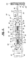
- Figure 2 is a perspective view of the subject invention shown in partial cross section;
- Figure 3 is a top view of the subject invention shown in a collapsed position and disposed within a vehicular seat;
- Figure 4 is a top view of the subject invention as in Figure 3 and shown in an extended position;
- Figure 5 is a front view of the subject invention shown with the pressure applicator in phantom and the hand crank in cross section;
- Figure 6 is an exploded view of the subject invention;
- Figure 7 is an enlarged view of the screw shaft and the mechanical locking means of the subject invention shown in a disconnected relationship;
- Figure 8 is a view as in Figure 7 showing the screw shaft being forcibly received in the mechanical locking means;
- Figure 9 is a view in Figures 7 and 8 showing the screw shaft forcibly received in the mechanical locking means in a mechanical interlock position;
- Figure 10 is a perspective view of an alternative embodiment of the subject invention including a vertical adjustment means; and
- Figure 11 is yet another perspective view of the alternative embodiment of the subject invention as shown in Figure 10.
- Referring to Figures 1-9, wherein like numerals indicate like or corresponding parts throughout the several views, an adjustable lumbar support assembly is generally shown at 20. A seat assembly is generally indicated at 22 and includes a
backrest portion 24 and aseat portion 26. A lumbar region of thebackrest 24 is generally represented by thebracketed area 28, as shown in Figure 1. - The
lumbar support assembly 20 is disposed within thebackrest 24 for altering the contour of thebackrest 24 to provide adjustable lumbar support within thelumbar region 28. Thelumbar support assembly 20 includes a lumbar adjustor means, generally indicated at 30, which is enclosed within theseat backrest 24 for incrementally adjusting the contour of thebackrest 24 to provide variable lumbar support. The lumbar adjustor means 30 comprises the structure moving within thebackrest 24 to physically alter the contour of thebackrest 24 inwardly or outwardly such that pressure is applied in various increments to the lumbar region of an occupant in theseat assembly 22. A support means, generally indicated at 32, is provided for attachment to thebackrest 24 for supporting the lumbar adjustor means 30 on thebackrest 24. Therefore, the support means 32 provides an interface between the lumbar adjustor means 30 and thebackrest 24 to support the lumbar adjustor means 30 for movement within thebackrest 24. - The improvement of the subject invention comprises a mechanical locking means, generally indicated at 34, for forcibly receiving the lumbar adjustor means 30 on the support means 32 as the lumbar adjustor means 30 is moved into a mechanical interlocked position with the support means 32 to allow rapid assembly of the lumbar adjustor means 30 and the support means 32 as an operational unit to be installed within the
backrest 24. That is, the mechanical locking means 34 provides automatic fastening and connecting of the lumbar adjustor means 30 and the support means 32 in response to a forced movement of the lumbar adjustor means 30 into a mechanically interlocked position on the support means 32. The mechanical locking means 34 allows rapid and simple connection of the elements of the subject invention without the need for additional tools or time consuming manufacturing assembly operations. - The lumbar adjustor means 30 includes an
elongated screw shaft 36 having a generally horizontal longitudinal axis. Thescrew shaft 36 is supported on the mechanical locking means 34 for rotation about its longitudinal axis. As best shown in Figures 2-6, thescrew shaft 36 includes a first set ofexternal thread patterns 38 wound in the right hand direction. That is, the first set ofthreads 38 are male thread convolutions having a thread propagation tending to axially advance thescrew shaft 36 when rotated in a clockwise direction about the longitudinal axis. Thescrew shaft 36 also includes a second set ofexternal thread patterns 40 which are spaced axially from thefirst threads 38. Thesecond threads 40 are male thread convolutions having a left hand propagation causing retraction of thescrew shaft 36 when rotated in a clockwise direction about its longitudinal axis. - A first nut-
like travelling member 42 is disposed in operative engagement with thefirst threads 38 and supported for non-rotating linear movement along thescrew shaft 36. Likewise, a second nut-like travelingmember 44 is operatively engaged with thesecond threads 40 and also supported for non-rotating linear movement along thescrew shaft 36. The first 42 and second 44 travelling members, as perhaps best shown in Figure 2, have a generally cubical shape with an internally threaded bore extending centrally through each member. As best shown in Figures 5 and 6, thefirst travelling member 42 includes a pair ofpintles 46 extending therefrom and disposed on opposite sides of the longitudinal axis of thescrew shaft 36. By way of reference to the drawing Figures, thepintles 46 extend from the top and bottom surfaces of the cubicalfirst travelling member 42. Similarly, thesecond travelling member 44 includes a pair ofpintles 48 extending therefrom and disposed on opposite sides of the longitudinal axis. - Referring again to Figure 2, a
first link 50 is pivotally connected to thefirst travelling member 42. Thefirst link 50 has a generally U-shaped cross section comprised of upper and lower parallel struts 52 interconnected by anintegral bridge 54. Thestruts 52 are slightly longer than thebridge 54 such that the distal ends are flexible and resilient when thefirst link 50 is fabricated from a resilient material such as plastic. Adjacent to the location where thefirst link 50 is pivotally attached to the first travellingmember 42, each of thestruts 52 include a hole for pivotally receiving thepintles 46 on the first travellingmember 42. For reasons to be described subsequently, aspacer 56 is disposed over thepintle 46 and between one of thestruts 52 and the first travellingmember 42, as shown in Figure 5. - Similarly, a
second link 58 is pivotally connected to the second travellingmember 44. Thesecond link 58 is identical to thefirst link 50 and includes upper andlower struts 60 maintained spaced and parallel by a connectingbridge 62. A pair of aligned holes in thestruts 60 pivotally receive thepintles 48 of the second travellingmember 44 for establishing the pivotal connection between the two elements. Aspacer 64 is disposed on one of thepintles 48 and positioned between the second travellingmember 44 and one of thestruts 60, as shown in Figure 5. - The first 50 and second 58 links are pivotally connected to one another at a displaceable joint 66 which is spaced from the first 42 and second 44 travelling members. More particularly, the displaceable joint 66 resembles a cross member to which each of the first 50 and second 58 links are connected in overlapping fashion. As best shown in Figures 2 and 5, the first 50 and second 58 links are interleaved with one another at the displaceable joint 66 and, for this reason, the
spacers members - The lumbar adjustor means 30 further includes a substantially
rigid pressure applicator 68 for forcibly altering the contour of thebackrest 24. Thepressure applicator 68 comprises a paddle-shaped member having two sheet-likeplanar jutting surfaces 70 spaced on opposite sides of a sheet-like planar middle recessedsurface 72. Extending rearwardly of the recessedsurface 72 are a pair of spacedtabs 74. Thetabs 74 extend in generally parallel vertical planes and each include ahole 76, as shown in Figure 6. Theholes 76 of each of thetabs 74 are aligned along a horizontal axis. - It is shown in the Figures, the displaceable joint 66 comprises a universal spider-type joint. That is, two vertically spaced
displacement pintles 78 of the displaceable joint 66 engage and pivotally connect the first 50 and second 58 links while two horizontally spacedapplicator pintles 80 engage and pivotally support theholes 76 of thetabs 74 such that thepressure applicator 68 is universally pivotally connected to the first 50 and second 58 links. - In the preferred embodiment, the
tabs 74 of thepressure applicator 68 are sufficiently flexible and resilient so that the displaceable joint 66 can be inserted into the tab holes 76 without the aid of special tools or disassembly of the elements. Likewise, the first 50 and second 58 links are fabricated from a resilient material which is sufficiently flexible to allow connection to the displaceable joint 66 and the respective first 42 and second 44 travelling members without special assembly techniques. Theresilient tabs 74 andlinks - The mechanical locking means 34 includes three
resilient prong members 82 extending from a fixed connection on the support means 32, as shown in Figure 6. The mechanical locking means 34 also includes asocket 84 likewise extending from a fixed connection on the support means 32. Theprongs 82 andsocket 84 are horizontally aligned on the support means 32 and extend outwardly therefrom in parallel vertical planes. Thesocket 84 is adapted to receive and rotatably support aterminal end 86 of thescrew shaft 36. Theprongs 82, on the other hand, forcibly receive thescrew shaft 36 at spaced locations and support thescrew shaft 36 for rotation about its longitudinal axis. - As best shown in Figures 7-9, the
prongs 82 have a circularinner bearing surface 88 matingly shaped to receive thescrew shaft 36. Retainingtips 90 flex outwardly as thescrew shaft 36 is forcibly moved toward theinner bearing surface 88, as shown in Figure 8. Once thescrew shaft 36 is moved contiguous theinner bearing surface 88, the retainingtips 90 flex back inwardly and support thescrew shaft 36 for rotation, as shown in Figure 9. - Therefore, during assembly of the subject lumbar adjustor means 30 and support means 32, the first 42 and second 44 travelling members are first assembled onto the respective first 38 and second 40 threads, with the
respective pintles respective pintles displacement pintles 78 of the displaceable joint 66. The applicator pintles 80 are next forcibly received in theholes 76 of thetabs 74 of thepressure applicator 68. With the lumbar adjustor means 30 thus assembled, theterminal end 86 of thescrew shaft 36 is inserted into thesocket 84 and thescrew shaft 36 is moved toward theprongs 82 such that thescrew shaft 36 is forcibly received in theprongs 82 and supported therein for rotation. - The support means 32 comprises a plate-like member having a
fastening lip 92 disposed at one end thereof and a pair of spacedopenings 94 at the other end thereof. Anelongated groove 96 extends horizontally into the support means 32, between the twoopenings 94, through which thescrew shaft 36 may pass. Abackset plate 98 is integrally disposed intermediate thefastening lip 92 and theopenings 94 and supports theprongs 82 andsocket 84. When thescrew shaft 36 is rotatably supported in theprongs 82 andsocket 84, the first 42 and second 44 travelling members engage thebackset plate 98. When thescrew shaft 36 is rotated in theprongs 82 andsocket 84, thebackset plate 98 prevents rotation of the travellingmembers members screw shaft 36. - Referring now to Figures 3 and 4, the
backrest 24 is shown includingstructural frame members 100 each having an oval tubular cross section. As viewed from Figures 3 and 4, theframe members 100 on the right side of thebackrest 24 include an inwardly extending mountingbracket 102. Disposed in the mountingbracket 102 is a vertically extending slot adapted to receive thefastening lip 92 of the support means 32. Extending inwardly from the leftside frame members 100 is asimilar mounting bracket 104. The mountingbracket 104 includes a pair of vertically spaced holes adapted to align with theopenings 94 in the support means 32. Therefore, when the support means 32 is mounted to the mountingbrackets openings 94 and the corresponding holes in the mountingbracket 104 to fixedly support theassembly 20 in thebackrest 24. - As shown in Figures 1 and 2, a rotary input comprising a hand crank 106 is provided for rotating the
screw shaft 36. A rotation multiplier means 108, 108' is provided in association with the hand crank 106 for rotating thescrew shaft 36 in the mechanical locking means 34 at a higher rotational velocity than the hand crank 106. Two alternative embodiments of the rotation multiplier means 108, 108' are shown in Figures 1 and 2. In Figure 1, the rotation multiplier means 108 is shown with abelt pulley 110 operatively engaged to the hand crank 106 and disposed for operative engagement with thescrew shaft 36. Alternatively, in Figure 2, the rotation multiplier means 108' is shown with the hand crank 106 having an internal annular gear set 112 disposed in matingly engagement with apinion gear 114 extending integrally from thescrew shaft 36. In either version of the rotation multiplier means 108, 108', the hand crank 106 is supported for rotation on the side of thebackrest 24 in a conventional manner. - Referring to Figures 10 and 11, an alternative, or modified, version of the support means 32' is shown including a vertical adjustment means, generally indicated at 116, for adjusting the lumbar adjustor means 30 vertically within the
backrest 24. In Figure 10, atubular backrest frame 118 is shown including a horizontalupper cross piece 120 and a vertically spacedlower cross piece 122. - Two spaced apart
vertical guide members 124 are fixed to thebackrest frame 118. More specifically, each of thevertical guide members 124 include a tongue disposed at the lower end thereof and adapted to be received in aslot 126 in thelower cross piece 122. Aresilient spring clip 128 is integrally formed at the upper end of eachvertical guide member 124. Theupper cross piece 120 is shaped and so disposed as to be forcibly received in theclip 128 and fixedly supported therein in a mechanically interlocked position. Therefore, thevertical guide members 124 are supported between the upper 120 and lower 122 cross pieces of thebackrest frame 118. Aspanner 130 is fixedly connected to and extends horizontally between each of thevertical guide members 124, midway between the upper 120 and lower 122 cross pieces. A plate-like arm 132 is disposed in a generally horizontal plane and extends forwardly from thespanner 130. - The support means 32' further includes a
carriage 134 which is moveably connected to thevertical guide members 124, as shown in Figure 10. Thecarriage 134 supports the mechanical locking means 34 and, thus, thescrew shaft 36,links pressure applicator 68. As thecarriage 134 is moveable linearly along thevertical guide members 124, thepressure applicator 68 is likewise adjustable vertically within the backrest to provide lumbar support at different vertical positions. - A worm mechanism, generally indicated at 136, operatively interconnects the
vertical guide members 124 and thecarriage 134, and more specifically thespanner 130 and thecarriage 134. Theworm mechanism 136 includes anut 138 fixedly attached to thecarriage 134 and ascrew element 140 rotatably supported on thearm 132 of thespanner 130. Therefore, as thescrew element 140 rotates, it displaces thenut 138, and hence thecarriage 134, linearly along thevertical guide members 124. - The
screw element 140 is connected to a flexible motion transmitting core element supported for rotation within aconduit 142. Theconduit 142, and hence the core element, extend from thearm 132 to a remoterotary actuator 144. In the preferred embodiment shown in Figure 10, the remoterotary actuator 144 is coaxially located with the hand crank 106 to provide a compact assembly on the exterior of thebackrest 24. Because thecarriage 134, and hence thescrew shaft 136, are moveably disposed within the backrest, thescrew shaft 36 must also be connected to the hand crank 106 through a flexible motion transmitting assembly as indicated at 146. - The subject invention is particularly advantageous when mass produced for high volume sale due to the decreased assembly time required to operatively connect the various moving elements. As each of the connected elements are snap-fit together, special tools are not required. Further, as best shown in Figure 3, the subject invention has a very thin profile and therefore nests neatly within the
backrest 24. Further, because many of the elements are fabricated from an elastomeric polymeric material, additional weight savings over prior art assemblies can be realized. - The invention has been described in an illustrative manner, and it is to be understood that the terminology which has been used is intended to be in the nature of words of description rather than of limitation.
- Obviously, many modifications and variations of the present invention are possible in light of the above teachings. It is, therefore, to be understood that within the scope of the appended claims wherein reference numerals are merely for convenience and are not to be in any way limiting, the invention may be practiced otherwise than as specifically described.
Claims (10)
- An adjustable lumbar support assembly (20) of the type disposed within a seat backrest (24) for altering the contour of the backrest (24) to provide lumbar support, said assembly (20) comprising: lumbar adjustor means (30) adapted for inclusion within a seat backrest (24) for incrementally adjusting the contour of the backrest (24) to provide variable lumbar support; support means (32, 32') for attachment to the backrest (24) for supporting said lumbar adjustor means (30) on the backrest (24); and characterized by mechanical locking means (34) for forcibly receiving said lumbar adjustor means (30) on said support means (32, 32') as said lumbar adjustor means (30) is moved into a mechanical interlocked position with said support means (32, 32') to allow rapid assembly of said lumbar adjustor means (30) and said support means (32, 32') as an operational unit to be installed within a seat backrest (24).
- An assembly (20) as set forth in claim 1 further characterized by said lumbar adjustor means (30) including an elongated screw shaft (36) having a longitudinal axis and supported on said mechanical locking means (34) for rotation about said longitudinal axis.
- An assembly (20) as set forth in claim 2 further characterized by said mechanical locking means (34) including at least one resilient prong member (82) extending from a fixed connection on said support means (32, 32').
- An assembly (20) as set forth in claim 3 further characterized by said screw shaft (36) including a first set of thread patterns (38) disposed in a right hand propagation and an axially spaced second set of thread patterns (40) disposed in a left hand propagation.
- An assembly (20) as set forth in claim 4 further characterized by said lumbar adjustor means (30) including a first travelling member (42) disposed in operative engagement with said first set of thread patterns (38) and supported for non-rotating linear movement along said screw shaft (36), and a second travelling member (44) disposed in operative engagement with said second set of thread patterns (40) supported for non-rotating linear movement along said screw shaft (36).
- An assembly (20) as set forth in claim 5 further characterized by said lumbar adjustor means (30) including a first link (50) pivotally connected to said first travelling member (42) and a second link (58) pivotally connected to said second travelling member (44) with said first link (50) and said second link (58) being pivotally connected to one another at a displaceable joint (66) spaced from said first (42) and second (44) travelling members.
- An assembly (20) as set forth in claim 6 further characterized by said lumbar adjustor means (30) including a substantially rigid pressure applicator (68) for forcibly altering the contour of the backrest (24).
- An assembly (20) as set forth in Claim 7 further characterized by said lumbar adjuster means (30) including a universal joint connection (66) between said pressure applicator (68) and said first (50) and second (58) links.
- An assembly (20) as set forth in Claim 8 further characterized by said first link (50) and said second link (58) being fabricated from a resilient material.
- An assembly (20) as set forth in Claim 8 further characterized by said first (42) and said second (44) travelling members each including a pair of pintles (46,48) extending therefrom and disposed on opposite sides of said longitudinal axis, said universal joint connection (66) including a pair of displacement pintles (78) extending outwardly toward and pivotally connecting to both of said first (50) and second (58) links, a pair of applicator pintles (80) extending outwardly toward and pivotally connecting to said pressure applicator (68), said pressure applicator (68) including two inwardly extending resilient tabs (76) for pivotally engaging said pair of applicator pintles (80), and said lumbar adjustor means (30) including rotation multiplier means (108,108') having a rotary input (106) for rotating said screw shaft (36) in said mechanical locking means (34) at a higher rotational velocity than said rotary input (106).
Applications Claiming Priority (2)
| Application Number | Priority Date | Filing Date | Title |
|---|---|---|---|
| US526454 | 1990-05-21 | ||
| US07/526,454 US5088790A (en) | 1990-05-21 | 1990-05-21 | Adjustable lumbar support mechanism for a vehicular seat |
Publications (1)
| Publication Number | Publication Date |
|---|---|
| EP0458440A1 true EP0458440A1 (en) | 1991-11-27 |
Family
ID=24097420
Family Applications (1)
| Application Number | Title | Priority Date | Filing Date |
|---|---|---|---|
| EP91301670A Withdrawn EP0458440A1 (en) | 1990-05-21 | 1991-02-28 | Adjustable lumbar support mechanism for a vehicular seat |
Country Status (2)
| Country | Link |
|---|---|
| US (1) | US5088790A (en) |
| EP (1) | EP0458440A1 (en) |
Cited By (13)
| Publication number | Priority date | Publication date | Assignee | Title |
|---|---|---|---|---|
| DE19848400A1 (en) * | 1998-10-21 | 2000-05-25 | Dlw Bueroeinrichtungen Gmbh | Chair has flexible cover and adjustable back rest to give better support of the back |
| US6695402B2 (en) * | 2002-03-29 | 2004-02-24 | Paul H. Sloan, Jr. | Adjustable lumbar support |
| WO2005023585A1 (en) | 2003-09-04 | 2005-03-17 | Brose Fahrzeugteile Gmbh & Co. Kg, Coburg | Motor vehicle seat back structure |
| WO2006029204A1 (en) * | 2004-09-07 | 2006-03-16 | L & P Property Management Company | Mechanism for thin seat lumbar |
| DE102008047249A1 (en) * | 2008-09-10 | 2010-03-11 | Brose Fahrzeugteile Gmbh & Co. Kommanditgesellschaft, Coburg | Backrest structure for a motor vehicle seat |
| WO2010028411A1 (en) * | 2008-09-15 | 2010-03-18 | Bene Ag | Support device for the lumbar vertebrae area |
| WO2012039854A2 (en) | 2010-09-21 | 2012-03-29 | La-Z-Boy Incorporated | Power lift lumbar support system |
| WO2013119172A1 (en) * | 2012-02-06 | 2013-08-15 | Lt Office Line Ab | Office chair with an adaptable lumbar support |
| US8684460B2 (en) | 2011-06-15 | 2014-04-01 | Brose Fahrzeugteile Gmbh & Co. Kg, Coburg | Backrest structure for a seat with lumbar support and curving element comprising a pre-tensioning connecting element |
| DE102012111888A1 (en) * | 2012-12-06 | 2014-06-12 | Recaro Aircraft Seating Gmbh & Co. Kg | Seat component of vehicle seat e.g. aircraft seat has transmission unit that translates force component in direction of bearing surface corresponding to movement of seat unit towards motion resistant direction |
| US10952535B2 (en) | 2018-11-05 | 2021-03-23 | La-Z-Boy Incorporated | Furniture member having lumbar adjustment mechanism |
| US11324324B2 (en) | 2018-11-05 | 2022-05-10 | La-Z-Boy Incorporated | Furniture member having lumbar adjustment mechanism |
| US11672348B2 (en) | 2018-11-05 | 2023-06-13 | La-Z-Boy Incorporated | Furniture member having lumbar adjustment mechanism |
Families Citing this family (84)
| Publication number | Priority date | Publication date | Assignee | Title |
|---|---|---|---|---|
| AT394829B (en) | 1989-08-04 | 1992-06-25 | Schuster Wilhelm | BACKREST FOR A VEHICLE SEAT, WITH AN ADJUSTABLE LUMBAR REST |
| IL95262A (en) * | 1990-08-01 | 1992-06-21 | Cohen Gideon | Orthopedic cushion |
| DE4228637A1 (en) * | 1992-08-28 | 1994-03-03 | Roeder Soehne Sitzmoebelfab | Chair with a height-adjustable backrest |
| US5299851A (en) * | 1993-05-19 | 1994-04-05 | Lin Kuen Yuan | Adjustable cushion assembly for a chair |
| US5419614A (en) * | 1993-05-25 | 1995-05-30 | Simula Inc. | Crewseat with adjustable lumbar and thigh supports |
| DE4320105C1 (en) | 1993-06-17 | 1994-10-13 | Ameu Management Corp | Adjustment device for a flexurally elastic supporting element of a backrest |
| US5462335A (en) * | 1994-08-18 | 1995-10-31 | Perfection Spring & Stamping Corp. | Adjustable lumbar support for seat backs |
| US5553919A (en) * | 1994-10-11 | 1996-09-10 | Excellence Lumbar Corporation | Scissor jack lumbar support |
| US5588703A (en) * | 1995-10-12 | 1996-12-31 | Tachi-S Co., Ltd. | Lumbar support device for vehicle seat |
| US5791733A (en) * | 1996-02-09 | 1998-08-11 | Knoll, Inc. | Adjustable lumbar support |
| US5609394A (en) * | 1996-02-23 | 1997-03-11 | Ligon Brothers Manufacturing Company | Four-way lumbar support |
| EP0803400A3 (en) * | 1996-04-23 | 1998-12-09 | Lear Corporation | Vehicle seat lumbar support |
| US5823620A (en) * | 1997-04-17 | 1998-10-20 | Lear Corporation | Vehicle seat having lumbar support |
| JPH119384A (en) * | 1997-06-27 | 1999-01-19 | Aisin Seiki Co Ltd | Lumber supporting device |
| US6119463A (en) | 1998-05-12 | 2000-09-19 | Amerigon | Thermoelectric heat exchanger |
| SE517321C2 (en) * | 1999-07-13 | 2002-05-28 | Ergonomiprodukter I Bodafors A | Headrest device |
| AU783829B2 (en) * | 2000-09-28 | 2005-12-08 | Formway Furniture Limited | A reclinable chair |
| US6619739B2 (en) * | 2001-03-01 | 2003-09-16 | L & P Property Management Company | Universal ergonomic support with self-contained actuator |
| US6758522B2 (en) | 2001-03-29 | 2004-07-06 | L&P Property Management Company | Apparatus and method for varying coefficients of friction in a variable apex back support |
| WO2003031222A1 (en) | 2001-10-11 | 2003-04-17 | L & P Property Mangement Company | Power lumbar mechanism |
| US6652028B2 (en) * | 2001-11-02 | 2003-11-25 | L & P Property Management | Apparatus and method for lumbar support with variable apex |
| US6676214B2 (en) | 2001-11-16 | 2004-01-13 | L & P Property Management Company | Method and apparatus for lumbar support with integrated actuator housing |
| US6908152B2 (en) | 2001-12-14 | 2005-06-21 | L & P Property Management Company | Push lumbar support with flexible pressure surface |
| US6779844B2 (en) | 2001-12-14 | 2004-08-24 | L&P Propety Maqnagement Company | Arching lumbar support with weight distribution surface |
| US6652029B2 (en) | 2001-12-20 | 2003-11-25 | L & P Property Management Company | Unitized back plate and lumbar support |
| US6908153B2 (en) | 2002-12-02 | 2005-06-21 | L&P Property Management Company | Power lumbar support cable apparatus and method |
| US7052087B2 (en) | 2002-12-09 | 2006-05-30 | L&P Property Management Company | Method and apparatus for a scissors ergonomic support |
| US7137664B2 (en) * | 2003-01-22 | 2006-11-21 | L&P Property Management Company | Automatically actuating ergonomic support system for a fold down seat |
| US7140680B2 (en) * | 2003-01-22 | 2006-11-28 | L&P Property Management Company | Fold down seat lumbar support apparatus and method |
| US6905170B2 (en) * | 2003-01-22 | 2005-06-14 | L & P Property Management Company | Fold down seat lumbar support apparatus and method |
| DE112005000235B4 (en) * | 2004-02-06 | 2011-07-14 | L&P Property Management Co., Calif. | drive mechanism |
| US7458637B2 (en) * | 2004-06-10 | 2008-12-02 | Steelcase Inc. | Back construction with flexible lumbar |
| CN100545000C (en) | 2004-07-30 | 2009-09-30 | L&P产权管理公司 | Modular lumbar support apparatus |
| US20070262621A1 (en) * | 2004-10-25 | 2007-11-15 | Hanh Dong | Apparatus for providing fluid through a vehicle seat |
| US20060087160A1 (en) * | 2004-10-25 | 2006-04-27 | Hanh Dong | Apparatus for providing fluid through a vehicle seat |
| US7587901B2 (en) | 2004-12-20 | 2009-09-15 | Amerigon Incorporated | Control system for thermal module in vehicle |
| EP1680983B1 (en) * | 2005-01-12 | 2012-11-28 | L&P Swiss Holding Company | Seat structure comprising a coupling unit |
| EP1680984B1 (en) | 2005-01-12 | 2007-08-15 | L&P Swiss Holding Company | Lumbar support assembly and corresponding seat structure |
| US7827805B2 (en) | 2005-03-23 | 2010-11-09 | Amerigon Incorporated | Seat climate control system |
| US20060214480A1 (en) * | 2005-03-23 | 2006-09-28 | John Terech | Vehicle seat with thermal elements |
| DE102005058904A1 (en) * | 2005-05-12 | 2006-11-16 | Brose Fahrzeugteile Gmbh & Co. Kommanditgesellschaft, Coburg | Lordosenversteller for a motor vehicle seat |
| US20060267382A1 (en) * | 2005-05-18 | 2006-11-30 | Schukra Of North America | Arm rest return |
| WO2006122420A1 (en) * | 2005-05-18 | 2006-11-23 | Schukra Of North America, Ltd. | Dual hinge belt lumbar |
| WO2006128431A1 (en) * | 2005-05-30 | 2006-12-07 | Brose Fahrzeugteile Gmbh & Co. Kg, Coburg | Manual adjustment of a back support on a vehicle seat |
| DE102005027922B3 (en) * | 2005-06-16 | 2007-01-11 | Schukra Gerätebau AG | lumbar support |
| US7448684B2 (en) * | 2005-06-28 | 2008-11-11 | Chen Hsing Enterprise Co., Ltd. | Backrest adjustment device |
| US7866621B1 (en) | 2006-09-27 | 2011-01-11 | Peerless Industries, Inc. | Pull-out swivel mount |
| US7490899B2 (en) * | 2006-03-30 | 2009-02-17 | Schukra Of North America | Combination lumbar-bolster system |
| US8539624B2 (en) | 2006-05-31 | 2013-09-24 | Gentherm Incorporated | Structure based fluid distribution system |
| US20080087316A1 (en) | 2006-10-12 | 2008-04-17 | Masa Inaba | Thermoelectric device with internal sensor |
| WO2008057962A2 (en) * | 2006-11-01 | 2008-05-15 | Amerigon Incorporated | Chair with air conditioning device |
| WO2008070991A1 (en) | 2006-12-11 | 2008-06-19 | Schukra Of North America, Ltd. | Lumbar system for climate seating |
| US7984949B2 (en) * | 2007-04-24 | 2011-07-26 | Schukra Of North America | Lumbar and bolster support for second row seat |
| WO2009036077A1 (en) | 2007-09-10 | 2009-03-19 | Amerigon, Inc. | Operational control schemes for ventilated seat or bed assemblies |
| DE602007001694D1 (en) * | 2007-09-21 | 2009-09-03 | Ciar Spa | lumbar support |
| CN110027454B (en) | 2008-02-01 | 2022-04-08 | 金瑟姆股份公司 | Condensation and humidity sensor for thermoelectric devices |
| US7997650B2 (en) | 2008-02-22 | 2011-08-16 | Schukra Of North America | Constant pressure retreating lumbar system |
| WO2010009422A1 (en) | 2008-07-18 | 2010-01-21 | Amerigon Incorporated | Climate controlled bed assembly |
| KR101063388B1 (en) * | 2008-11-27 | 2011-09-07 | 기아자동차주식회사 | Lumbar support of vehicle seat |
| JP5576111B2 (en) * | 2009-12-28 | 2014-08-20 | テイ・エス テック株式会社 | Vehicle seat |
| US9121414B2 (en) | 2010-11-05 | 2015-09-01 | Gentherm Incorporated | Low-profile blowers and methods |
| TWM417072U (en) * | 2011-02-22 | 2011-12-01 | Chern Shing Top Co Ltd | Improved structure of seat back cushion |
| US9685599B2 (en) | 2011-10-07 | 2017-06-20 | Gentherm Incorporated | Method and system for controlling an operation of a thermoelectric device |
| US9989267B2 (en) | 2012-02-10 | 2018-06-05 | Gentherm Incorporated | Moisture abatement in heating operation of climate controlled systems |
| CN104718106B (en) | 2012-10-01 | 2018-04-27 | 提爱思科技股份有限公司 | Backrest |
| US9662962B2 (en) | 2013-11-05 | 2017-05-30 | Gentherm Incorporated | Vehicle headliner assembly for zonal comfort |
| US10589647B2 (en) | 2013-12-05 | 2020-03-17 | Gentherm Incorporated | Systems and methods for climate controlled seats |
| DE112015000816T5 (en) | 2014-02-14 | 2016-11-03 | Gentherm Incorporated | Conductive, convective air-conditioned seat |
| KR101592754B1 (en) * | 2014-08-22 | 2016-02-12 | 현대자동차주식회사 | Lumbar support for vehicle |
| US11639816B2 (en) | 2014-11-14 | 2023-05-02 | Gentherm Incorporated | Heating and cooling technologies including temperature regulating pad wrap and technologies with liquid system |
| EP3726594B1 (en) | 2014-11-14 | 2022-05-04 | Gentherm Incorporated | Heating and cooling technologies |
| US11857004B2 (en) | 2014-11-14 | 2024-01-02 | Gentherm Incorporated | Heating and cooling technologies |
| US10085564B2 (en) * | 2016-02-02 | 2018-10-02 | L & P Property Management Company | Adjustable lumbar support for upholstery furniture |
| CN106740344A (en) * | 2016-12-30 | 2017-05-31 | 芜湖瑞泰汽车零部件有限公司 | For the waist support of seat |
| CN106696796A (en) * | 2016-12-30 | 2017-05-24 | 芜湖瑞泰汽车零部件有限公司 | Chair waist support |
| CN106953463A (en) * | 2017-04-24 | 2017-07-14 | 泰州市瑞美机械有限公司 | Integrated form chair rack motor transmission component |
| CN110179285A (en) * | 2018-02-22 | 2019-08-30 | 佛山市南海德天家具有限公司 | A kind of screw rod transversal-push type hardness regulating device and its seat, mattress |
| US20200035898A1 (en) | 2018-07-30 | 2020-01-30 | Gentherm Incorporated | Thermoelectric device having circuitry that facilitates manufacture |
| US11993132B2 (en) | 2018-11-30 | 2024-05-28 | Gentherm Incorporated | Thermoelectric conditioning system and methods |
| US11152557B2 (en) | 2019-02-20 | 2021-10-19 | Gentherm Incorporated | Thermoelectric module with integrated printed circuit board |
| US11246420B1 (en) | 2019-03-01 | 2022-02-15 | Ashley Furniture Industries, Llc | Adjustable lumbar support |
| KR102726789B1 (en) * | 2019-04-22 | 2024-11-05 | 현대자동차주식회사 | Lumber support device for seat of vehicle |
| CN112428899B (en) * | 2020-11-30 | 2022-09-06 | 重庆长安汽车股份有限公司 | Seat hinge structure and seat back mounting structure |
| KR102597544B1 (en) * | 2021-04-02 | 2023-11-03 | 주식회사 디에스시동탄 | Support driver and support assembly including the same |
Citations (2)
| Publication number | Priority date | Publication date | Assignee | Title |
|---|---|---|---|---|
| EP0026668A2 (en) * | 1979-09-28 | 1981-04-08 | Uop Inc. | Seat backrest having an adjustable lumbar support |
| US4389135A (en) * | 1981-06-30 | 1983-06-21 | Jack Peters | Releasable locking device |
Family Cites Families (6)
| Publication number | Priority date | Publication date | Assignee | Title |
|---|---|---|---|---|
| GB2035071A (en) * | 1978-11-18 | 1980-06-18 | Uop Inc | Seat having a movable lumbar support |
| US4295681A (en) * | 1980-02-19 | 1981-10-20 | Uop Inc. | Seat having lumbar support and vertical height adjustment mechanism therefor |
| DE3482372D1 (en) * | 1983-10-14 | 1990-07-05 | Graeme John Winkle | IMPROVED BACKREST. |
| US4657304A (en) * | 1986-06-06 | 1987-04-14 | Itt Corporation | Adjustable headrest |
| JPH0612711Y2 (en) * | 1989-05-08 | 1994-04-06 | シロキ工業株式会社 | Sheet |
| US4981324A (en) * | 1989-10-13 | 1991-01-01 | Law Ignace K | Ventilated back-seat support pad particularly for vehicles |
-
1990
- 1990-05-21 US US07/526,454 patent/US5088790A/en not_active Expired - Fee Related
-
1991
- 1991-02-28 EP EP91301670A patent/EP0458440A1/en not_active Withdrawn
Patent Citations (2)
| Publication number | Priority date | Publication date | Assignee | Title |
|---|---|---|---|---|
| EP0026668A2 (en) * | 1979-09-28 | 1981-04-08 | Uop Inc. | Seat backrest having an adjustable lumbar support |
| US4389135A (en) * | 1981-06-30 | 1983-06-21 | Jack Peters | Releasable locking device |
Cited By (26)
| Publication number | Priority date | Publication date | Assignee | Title |
|---|---|---|---|---|
| DE19848400A1 (en) * | 1998-10-21 | 2000-05-25 | Dlw Bueroeinrichtungen Gmbh | Chair has flexible cover and adjustable back rest to give better support of the back |
| US6695402B2 (en) * | 2002-03-29 | 2004-02-24 | Paul H. Sloan, Jr. | Adjustable lumbar support |
| US7488039B2 (en) | 2003-09-04 | 2009-02-10 | Brose Fahrzeugteile Gmbh & Co. Kg, Coburg | Motor vehicle seat back structure for a motor vehicle seat |
| US7690727B2 (en) | 2003-09-04 | 2010-04-06 | Brose Fahrzeugteile Gmbh & Co. Kg, Coburg | Motor vehicle seat back structure for a motor vehicle seat |
| WO2005023585A1 (en) | 2003-09-04 | 2005-03-17 | Brose Fahrzeugteile Gmbh & Co. Kg, Coburg | Motor vehicle seat back structure |
| US7549700B2 (en) | 2004-09-07 | 2009-06-23 | Schukra Of North America | Mechanism for thin seat lumbar |
| WO2006029204A1 (en) * | 2004-09-07 | 2006-03-16 | L & P Property Management Company | Mechanism for thin seat lumbar |
| DE102008047249A1 (en) * | 2008-09-10 | 2010-03-11 | Brose Fahrzeugteile Gmbh & Co. Kommanditgesellschaft, Coburg | Backrest structure for a motor vehicle seat |
| US8091966B2 (en) | 2008-09-10 | 2012-01-10 | Brose Fahrzeugteile Gmbh & Co. Kg, Coburg | Backrest structure for a motor vehicle seat |
| CN101670802B (en) * | 2008-09-10 | 2013-09-04 | 布罗泽汽车部件制造科堡有限公司 | Backrest structure for a motor vehicle seat |
| WO2010028411A1 (en) * | 2008-09-15 | 2010-03-18 | Bene Ag | Support device for the lumbar vertebrae area |
| WO2012039854A2 (en) | 2010-09-21 | 2012-03-29 | La-Z-Boy Incorporated | Power lift lumbar support system |
| EP2618699A2 (en) * | 2010-09-21 | 2013-07-31 | LA-Z-BOY Incorporated | Power lift lumbar support system |
| US8807651B2 (en) | 2010-09-21 | 2014-08-19 | La-Z-Boy Incorporated | Power lift lumbar support system |
| EP2618699A4 (en) * | 2010-09-21 | 2014-02-19 | La Z Boy Inc | Power lift lumbar support system |
| US8684460B2 (en) | 2011-06-15 | 2014-04-01 | Brose Fahrzeugteile Gmbh & Co. Kg, Coburg | Backrest structure for a seat with lumbar support and curving element comprising a pre-tensioning connecting element |
| WO2013119172A1 (en) * | 2012-02-06 | 2013-08-15 | Lt Office Line Ab | Office chair with an adaptable lumbar support |
| CN104244773A (en) * | 2012-02-06 | 2014-12-24 | Lt欧菲姿莱茵公司 | Office chair with an adaptable lumbar support |
| US9351580B2 (en) | 2012-02-06 | 2016-05-31 | Lt Office Line Ab | Office chair with an adaptable lumbar support |
| CN104244773B (en) * | 2012-02-06 | 2017-02-22 | Lt欧菲姿莱茵公司 | Office chair with an adaptable lumbar support |
| DE102012111888A1 (en) * | 2012-12-06 | 2014-06-12 | Recaro Aircraft Seating Gmbh & Co. Kg | Seat component of vehicle seat e.g. aircraft seat has transmission unit that translates force component in direction of bearing surface corresponding to movement of seat unit towards motion resistant direction |
| US10952535B2 (en) | 2018-11-05 | 2021-03-23 | La-Z-Boy Incorporated | Furniture member having lumbar adjustment mechanism |
| US11284724B2 (en) | 2018-11-05 | 2022-03-29 | La-Z-Boy Incorporated | Furniture member having lumbar adjustment mechanism |
| US11324324B2 (en) | 2018-11-05 | 2022-05-10 | La-Z-Boy Incorporated | Furniture member having lumbar adjustment mechanism |
| GB2593612B (en) * | 2018-11-05 | 2022-09-14 | La Z Boy Inc | Furniture member having lumbar adjustment mechanism |
| US11672348B2 (en) | 2018-11-05 | 2023-06-13 | La-Z-Boy Incorporated | Furniture member having lumbar adjustment mechanism |
Also Published As
| Publication number | Publication date |
|---|---|
| US5088790A (en) | 1992-02-18 |
Similar Documents
| Publication | Publication Date | Title |
|---|---|---|
| US5088790A (en) | Adjustable lumbar support mechanism for a vehicular seat | |
| US7131694B1 (en) | Adjustable lumbar support for vehicle seat | |
| US6695402B2 (en) | Adjustable lumbar support | |
| EP2322058B2 (en) | Adjusting device for a lumbar support and method of adjusting a lumbar support | |
| US4623115A (en) | Preset mirror mount | |
| US6000757A (en) | Vehicle seat adjuster | |
| EP1101652B1 (en) | Reduction gear for vehicle seat | |
| EP0654377B1 (en) | Rear view mirror for motor vehicles | |
| US5797293A (en) | Plastic drive block for vehicle seat adjuster | |
| CA1292415C (en) | Motor-vehicle seat having lateral wings | |
| CA1289050C (en) | Telescopic screw jack for the adjustment of an element such as a vehicle seat | |
| EP1040962A2 (en) | Interior rear view mirror for vehicles, especially motor vehicles | |
| CN1097702A (en) | Perambulator | |
| WO2018127590A1 (en) | Motor-adjustable steering column for a motor vehicle | |
| DE10296371T5 (en) | Actuator for a lordosis unit with motor drive | |
| CA2184803A1 (en) | Simplified linear recliner | |
| US7252278B2 (en) | Drive nut and screw for seat adjuster | |
| CA2233999A1 (en) | Gimballed drive block for vehicle seat adjuster | |
| DE3138082A1 (en) | STABILIZING FASTENING DEVICE FOR AN ADJUSTABLE MIRROR | |
| EP0557697B1 (en) | Vehicle headlamp | |
| US11524713B2 (en) | Steering column for a motor vehicle | |
| GB2087973A (en) | Window regulator | |
| US5094419A (en) | Lift bar for power seat adjuster | |
| JP2003063284A (en) | Powder slide mechanism | |
| KR970001100B1 (en) | Power Drive of Car Seat Seat |
Legal Events
| Date | Code | Title | Description |
|---|---|---|---|
| PUAI | Public reference made under article 153(3) epc to a published international application that has entered the european phase |
Free format text: ORIGINAL CODE: 0009012 |
|
| AK | Designated contracting states |
Kind code of ref document: A1 Designated state(s): AT BE DE ES FR GB IT SE |
|
| STAA | Information on the status of an ep patent application or granted ep patent |
Free format text: STATUS: THE APPLICATION IS DEEMED TO BE WITHDRAWN |
|
| 18D | Application deemed to be withdrawn |
Effective date: 19920528 |