EP0458439A2 - Spheronizing process - Google Patents
Spheronizing process Download PDFInfo
- Publication number
- EP0458439A2 EP0458439A2 EP91301576A EP91301576A EP0458439A2 EP 0458439 A2 EP0458439 A2 EP 0458439A2 EP 91301576 A EP91301576 A EP 91301576A EP 91301576 A EP91301576 A EP 91301576A EP 0458439 A2 EP0458439 A2 EP 0458439A2
- Authority
- EP
- European Patent Office
- Prior art keywords
- gas generating
- wet mixture
- generating material
- spherical
- forming
- Prior art date
- Legal status (The legal status is an assumption and is not a legal conclusion. Google has not performed a legal analysis and makes no representation as to the accuracy of the status listed.)
- Granted
Links
Images


Classifications
-
- B—PERFORMING OPERATIONS; TRANSPORTING
- B29—WORKING OF PLASTICS; WORKING OF SUBSTANCES IN A PLASTIC STATE IN GENERAL
- B29B—PREPARATION OR PRETREATMENT OF THE MATERIAL TO BE SHAPED; MAKING GRANULES OR PREFORMS; RECOVERY OF PLASTICS OR OTHER CONSTITUENTS OF WASTE MATERIAL CONTAINING PLASTICS
- B29B9/00—Making granules
- B29B9/12—Making granules characterised by structure or composition
-
- B—PERFORMING OPERATIONS; TRANSPORTING
- B29—WORKING OF PLASTICS; WORKING OF SUBSTANCES IN A PLASTIC STATE IN GENERAL
- B29B—PREPARATION OR PRETREATMENT OF THE MATERIAL TO BE SHAPED; MAKING GRANULES OR PREFORMS; RECOVERY OF PLASTICS OR OTHER CONSTITUENTS OF WASTE MATERIAL CONTAINING PLASTICS
- B29B9/00—Making granules
- B29B9/08—Making granules by agglomerating smaller particles
-
- C—CHEMISTRY; METALLURGY
- C06—EXPLOSIVES; MATCHES
- C06B—EXPLOSIVES OR THERMIC COMPOSITIONS; MANUFACTURE THEREOF; USE OF SINGLE SUBSTANCES AS EXPLOSIVES
- C06B21/00—Apparatus or methods for working-up explosives, e.g. forming, cutting, drying
- C06B21/0033—Shaping the mixture
-
- C—CHEMISTRY; METALLURGY
- C06—EXPLOSIVES; MATCHES
- C06D—MEANS FOR GENERATING SMOKE OR MIST; GAS-ATTACK COMPOSITIONS; GENERATION OF GAS FOR BLASTING OR PROPULSION (CHEMICAL PART)
- C06D5/00—Generation of pressure gas, e.g. for blasting cartridges, starting cartridges, rockets
- C06D5/06—Generation of pressure gas, e.g. for blasting cartridges, starting cartridges, rockets by reaction of two or more solids
Definitions
- the present invention relates to a method of manufacturing gas generating material, and particularly to a method of making gas generating bodies from gas generating material.
- a gas generating body (known as a "grain") is used to generate gas to inflate a vehicle occupant restraint such as an airbag.
- U.S. Patent No. 4,696,705 assigned to the assignee of the present application, discloses such a gas generating body.
- the gas generating body when ignited generates nitrogen gas to inflate an airbag.
- the gas generating body preferably has a plurality of longitudinally extending passages parallel to the axis of the body.
- a progressive rate of burn is one in which the burning proceeds, for a substantial part of the burn cycle, at a rate which increases.
- the passages widen, exposing increasingly more surface area to burning.
- the outer circumference of the body of gas generating material shrinks, reducing the surface area exposed to burning, but this reduction in surface area is less than the increase in surface area produced by burning in the passages in the grain.
- the burn rate ceases to increase and remains constant until near the end of the burn cycle, at which time the rate of burn decreases to zero. Nonetheless, the period of increasing burn rate extends for a substantial part of the burn cycle.
- a body of gas generating material is manufactured by first producing a gas generating material in the form of a dry powder, flowing the dry powder into a die, and applying a high pressure to the powder so that the powder particles adhere to each other to form the body.
- U.S. Patent No. 4,696,705 discloses such a process.
- the present invention resides in a process for making gas generating material which can readily flow.
- the material When the material is directed into a die cavity, it completely fills the die cavity and surrounds the aforementioned pins which may be closely spaced in the die cavity. Thus, the aforementioned air pockets are not created, and breakage of the pins during pressing of the material is minimized.
- the process of making the gas generating material comprises the steps of (a) preparing a wet mixture of the ingredients of the gas generating material, (b) extruding the wet mixture, and then (c) forming the extrudate into spherical shaped granules. Since the granules are in a spherical shape they readily flow when in a dry state.
- the wet mixture of ingredients includes an azide and a metal oxide which is reactive with the azide.
- the wet mixture is preferably prepared with a relatively high moisture content, suitable for grinding. Prior to extruding, the wet mixture is dried to a moisture content effective for extruding.
- the extrudate is formed into a spherical shape by a spheronizer in which the extrudate is rolled into small diameter spheres.
- the present invention relates to a method of making gas generating material and particularly to a method of making a body (known as a "grain") of gas generating material for inflating a vehicle occupant restraint, such as an airbag.
- the body of gas generating material preferably has a progressive burn rate.
- the specific composition of the gas generating material may vary and the specific configuration of the body of gas generating material may also vary.
- a body 10 of gas generating material contains an alkali metal azide compound. This compound is represented by the formula MN3 where M is an alkali metal, preferably sodium or potassium, and N is nitrogen.
- the body 10 also contains an oxidant and may contain other materials such as a binder.
- a preferred oxidant is a metal oxide which is reactive with the alkali metal azide, more specifically a metal oxide wherein the metal of the oxide is lower in the electromotive series of elements than the alkali metal of the azide.
- suitable metal oxides are copper oxide, iron oxide, stannic oxide, titanium dioxide, lead oxide, chromium oxide and zinc oxide.
- a preferred metal oxide is iron oxide (Fe2O3).
- Suitable compositions for the body 10 are disclosed in U.S. Patent No. 4,817,828.
- the body 10 comprises 47.9% to 67.9% by weight of sodium azide, 0% to 10% by weight of sodium nitrate, 0% to 4% by weight of bentonite, 24.6% to 44.6% by weight of iron oxide, and 0% to 6% by weight of graphite fibers.
- a preferred composition of the body 10 is 57.9% by weight sodium azide, 34.6% by weight iron oxide, 2.5% by weight bentonite, 3% by weight graphite fibers, and 2% by weight sodium nitrate.
- the graphite fibers mechanically reinforce the body and help to minimize damage to the body and the resultant exposure of additional surface area which can accelerate the burn rate.
- the graphite fibers also provide mechanical reinforcement so that when the body 10 burns, it more readily forms a strong structural sinter.
- the sinter controls the combustion products of the grain.
- Other fibers, such as fiberglass and steel wool can be used instead of graphite.
- the bentonite functions as an extrusion aid.
- Other extrusion aids can be used.
- the sodium nitrate provides additional oxygen for combustion of the azide.
- Other inorganic oxides, such as potassium perchlorate, can be used.
- the composition can also contain other ingredients conventionally used in gas generating bodies, such as a sintering aid, e.g., aluminum oxide.
- the body 10 has a generally cylindrical shape and has a cylindrical central passage 40 with an axis disposed on the central axis of the grain.
- the passage 40 extends between axially opposite end faces 42, 44 (Fig. 2) of the body.
- the body 10 has a plurality of cylindrical passages 46 which are disposed radially outwardly relative to central passage 40 and which also extend longitudinally through the body between the opposite end faces 42, 44.
- the axes of the passages 46 are parallel to the axis of passage 40.
- the passages 46 are evenly spaced on concentric circles 47, 48, 50 which are radially spaced from passage 40, but co-axial with the axis of passage 40.
- the respective passages 46 on concentric circle 47 are spaced apart equal to the spacing of the passages 46 on concentric circles 48 and 50.
- the axes of the passages 46 on one of the concentric circles 47, 48 and 50 are offset circumferentially, to one side, from the axes of the passages 46 on the other concentric circles.
- a passage 46 on concentric circle 48 is spaced from an offset,passage 46 on concentric circle 50 the same distance that it is spaced from an adjacent passage 46 on concentric circle 48. Also, a passage 46 on concentric circle 48 is spaced from an offset passage 46 on concentric circle 47 the same distance that it is spaced from an adjacent passage 46 on concentric circle 48.
- a plurality of the bodies 10 are used to generate gas to inflate a vehicle occupant restraint such as an airbag.
- a plurality of bodies 10 are stacked together and, when ignited, generate gas which is filtered and directed into an airbag.
- the plurality of, bodies 10 are stacked so that the passages 46 in one body are aligned with the passages 46 in all of the other bodies.
- hot gas generated by burning one body flows through the passages 46 to ignite adjacent bodies, and the surfaces of the passages 46 of all of the bodies are quickly ignited.
- the gas which is generated within the passages 46 must be able to get out of the passages and flow radially of the, bodies into an airbag to inflate the airbag.
- spaces are provided between the end faces 42, 44 of adjacent bodies 10.
- the spaces extend radially outward from the central passage 40 of the bodies.
- the spaces between the ends of adjacent bodies are provided by axially projecting standoff pads 54, 56, Fig. 2, on the end faces 42, 44.
- the standoff pads of one body are aligned with those of an adjacent body so that the spaces between the bodies are provided by the standoff pads of adjacent bodies.
- Several standoff pads 54, 56 are positioned in circumferentially spaced apart relationship on each end face 42, 44 so as to maintain the end faces 42, 44 of adjacent bodies in spaced apart parallel planes.
- the plurality of passages 46 in a body 10 promote what has been referred to as a progressive rate of burn of a body.
- a progressive rate of burn is one in which the burning proceeds, for a substantial part of the burn cycle, at a rate which increases.
- the passages 46 widen, exposing increasingly more surface area to burning.
- the outer circumference of each body 10 shrinks, reducing the surface area exposed to burning, but this reduction in surface area is less than the increase in surface area produced by burning in the passages 46 in the body.
- the burn rate ceases to increase and remains constant until near the end of the burn cycle, at which time the rate of burn will decrease to zero.
- a progressive rate of burn is in contrast to a neutral rate of burn, in which a substantially constant grain surface area is exposed to burning throughout the burn cycle, as disclosed in prior U.S. Patent No. 4,200,615, and the burn rate, after an initial spurt, is essentially constant for most of the burn cycle.
- a progressive rate of burn is also different from a regressive rate of burn, in which the burning proceeds, from an initial high burst, at a decreasing rate for most of the burn cycle.
- a progressive burn rate allows the airbag to inflate more slowly when it is first emerging from the dashboard, thereby reducing the force of any impact of the bag against a passenger, such as a child. After the bag has emerged from the dashboard, the progressive burn rate allows the bag to fill at an increasing rate.
- the process of making a body 10, in accordance with the present invention begins with preparing a wet mixture or slurry of iron oxide, sodium azide, sodium nitrate and water.
- the wet mixture or slurry of gas generating material is wet milled or comminuted to a fine particle size in a colloid mill and then in a bead mill.
- the particle size of the solids in the wet mixture exiting from the bead mill is less than 5 microns.
- Graphite fibers and bentonite are then added to the wet mixture of gas generating material and further mixing is carried out. At this point, the wet mixture contains about 50% solids.
- the wet mixture is pumped to a known centrifuge where it is filtered to provide a moisture content of about 7% to 11% by weight, preferably 9% by weight.
- the centrifuge processes the wet mixture in discrete batches, each of which is acted upon by the centrifuge for a predetermined time period in the order of ten minutes.
- the wet mixture of gas generating material containing about 9% moisture, is then extruded by forcing the gas generating material through small openings.
- the material After extruding, the material is formed into small spherical balls in a spheronizer.
- the spheronized particles are conveyor dried, stored, for instance in a surge vessel, and then pressed into the desired shape.
- the bodies may be coated and then packaged.
- the filtrate from the centrifuge is recycled and used in making additional wet mixtures. In the recycle step, water, sodium azide, and sodium nitrate are added to the filtrate from the centrifuge.
- Fig. 4 shows the type of extruder 100 that may be employed in the practice of the present invention.
- the damp mixture from the centrifuge is introduced into a feed hopper 101 of the extruder 100.
- Twin transport screws 102 convey the damp material from the feed hopper 101 to the extrusion zone 103.
- the extrusion zone 103 is defined by a radial screen 104 encompassing a pair of parallel rotors 105, only one of which is shown in Fig. 4.
- the rotors 105 have longitudinally extending helical blades 106 and on rotation expel the material through the radial screen 104.
- the material, during expelling is formed into extrudate which drops from the screen as shown schematically in Fig. 4.
- the extruder screen has an average hole diameter of about 0.5 to about 0.7 millimeters.
- the extruder produces extrudate (Fig. 5) having a length of about 5 to about 20 millimeters and a diameter of about 0.5 to about 0.7 millimeters.
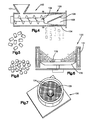
- the extrudate are then conveyed to a spheronizer 130 (Fig. 6).
- the spheronizer comprises a cylindrical housing 131 in which a rotatable disk 132 is supported, as shown in Fig. 6.
- the disk 132 has a waffle pattern on its upper face 133 comprising two sets of grooves 134 (Fig. 7) which intercept each other at right angles.
- the grooves 134 are nominally two millimeters in depth.
- the extrudate are introduced onto the disk 132, as shown in Fig. 6.
- the extrudate are broken up and are rolled into small spheres of about 0.5 to about 0.7 millimeters in diameter, having the configuration shown in Fig. 8.
- the material moves radially outwardly of the disk 132 and toward the housing 131.
- the resulting spheres exit from the disk at a location adjacent the periphery of the disk.
- the residence time of the material in the spheronizer is 15 to 20 seconds.
- the housing 131 is heated by flowing a heated fluid through conduits in the housing 131. Heating minimizes sticking of the material to the housing 131 and thus facilitates separation of the material from the housing 131.
- the small spheres after being formed are dried in a suitable dryer (Fig. 3).
- the dryer includes a plurality of disks which rotate in a chamber. Heated gas is directed through the chamber. The spheres drop onto a first disk, and as the disk rotates, the spheres are moved radially of the disk to a location where they drop onto the next disc. The spheres again move radially on the next disk as the next disk rotates, and then drop onto another disk. The spheres move from disk to disk until the spheres are dried to a desired moisture content.
- the time of residence of the spheres in the dryer is such that when they exit the dryer they have a moisture content of about 2 to 3 1/2% by weight.
- the spheres are then stored.
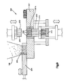
- the press 200 When needed to make grains, the dried spheres of gas generating material are placed in the feeder hopper 199 (Fig. 9) of a press 200 which forms the bodies 10.
- the press 200 includes a die 201 defining a die cavity 201a, a movable upper die plate 202, a movable lower die plate 203, and a material feed shoe 204.
- the material feed shoe 204 has a charge cavity 205 for granular material.
- the feed shoe 204 reciprocates between a first position shown in full lines in Fig. 9 and a second position in which the charge cavity 205 is aligned with the die cavity. In the first position, the spherical granules flow by gravity out of the feed hopper 199 into the charge cavity 205.
- the feed shoe is then reciprocated from the full line position in Fig. 9 to the second position in which the charge cavity 205 is aligned over the die cavity 201a. When in this position the spherical granules flow from the charge cavity 205 into the die cavity 201a.
- a plurality of stationary pins 208 extend vertically through the die cavity 201a.
- the pins are spaced approximately 1/10 of an inch or 2.54 millimeters from each other and are in an arrangement corresponding to the arrangement of the passages 40 and 46 in the body 10.
- the spherical granules because of their shape readily flow completely around the pins 208 and fill the die cavity 201a completely even though the pins 208 are very closely positioned relative to each other. Since the material readily flows into the die cavity 201a, the formation of air pockets in the material in the die cavity is minimized, and the breakage of the pins 208 is minimized.
- the feed shoe 204 After the die cavity 201a is filled, the feed shoe 204 returns to its first position to receive another charge of material from the feed hopper 199.
- the die plates 202 and 203 move relative to one another and apply pressure to the spherical granules in the die cavity 201a.
- the die plates 202, 203 have openings 209, 210, respectively, shown in dashed lines.
- the pins 208 are fixed to a support 212 and extend upwardly through the openings 210 in the die plate 203. When the upper die plate 202 moves downwardly, the openings 209 therein receive the ends of the pins 208. Thus, the pins 208 do not interfere with movement of either of the die plates 202, 203.
- the pressure which is applied to the material in the die cavity by die plates 202, 203 is in the order of 7 to 12 tons per square inch. This pressure causes the granules to adhere to each other and form the body 10.
- the upper die plate 202 is moved upwardly clear of the mold 201 and the lower die plate 202 is moved upwardly to eject the pressed finished body 10.
- the pressed finished body 10 is then moved by the lead end of the feed shoe 204 to a discharge location on the next movement of the feed shoe over the die cavity 201a.
Landscapes
- Chemical & Material Sciences (AREA)
- Engineering & Computer Science (AREA)
- Organic Chemistry (AREA)
- Mechanical Engineering (AREA)
- Chemical Kinetics & Catalysis (AREA)
- Combustion & Propulsion (AREA)
- Air Bags (AREA)
Abstract
Description
- The present invention relates to a method of manufacturing gas generating material, and particularly to a method of making gas generating bodies from gas generating material.
- A gas generating body (known as a "grain") is used to generate gas to inflate a vehicle occupant restraint such as an airbag. U.S. Patent No. 4,696,705, assigned to the assignee of the present application, discloses such a gas generating body. The gas generating body when ignited generates nitrogen gas to inflate an airbag. The gas generating body preferably has a plurality of longitudinally extending passages parallel to the axis of the body.
- Upon ignition of the gas generating body, it has a progressive rate of burn. A progressive rate of burn is one in which the burning proceeds, for a substantial part of the burn cycle, at a rate which increases. As the circumferential surfaces of the passages in the body burn, the passages widen, exposing increasingly more surface area to burning. Simultaneously, the outer circumference of the body of gas generating material shrinks, reducing the surface area exposed to burning, but this reduction in surface area is less than the increase in surface area produced by burning in the passages in the grain. At a point in the burn cycle, the burn rate ceases to increase and remains constant until near the end of the burn cycle, at which time the rate of burn decreases to zero. Nonetheless, the period of increasing burn rate extends for a substantial part of the burn cycle.
- Typically, a body of gas generating material is manufactured by first producing a gas generating material in the form of a dry powder, flowing the dry powder into a die, and applying a high pressure to the powder so that the powder particles adhere to each other to form the body. U.S. Patent No. 4,696,705 discloses such a process.
- In order to manufacture bodies of gas generating material which have a plurality of passages to provide a progressive rate of burn, it is necessary to have a plurality of closely spaced pins which extend longitudinally in a die cavity. The gas generating material is introduced into the die cavity around the pins. If the gas generating material does not flow readily into the die cavity and around the pins, air pockets can form in the material in the die cavity. When a high pressure is applied to the material in the die cavity, the material may apply a lateral force against a pin. If an air pocket is on the side of the pin opposite the direction of action of the lateral force, the pin may break.
- The present invention resides in a process for making gas generating material which can readily flow. When the material is directed into a die cavity, it completely fills the die cavity and surrounds the aforementioned pins which may be closely spaced in the die cavity. Thus, the aforementioned air pockets are not created, and breakage of the pins during pressing of the material is minimized.
- The process of making the gas generating material comprises the steps of (a) preparing a wet mixture of the ingredients of the gas generating material, (b) extruding the wet mixture, and then (c) forming the extrudate into spherical shaped granules. Since the granules are in a spherical shape they readily flow when in a dry state.
- Preferably, the wet mixture of ingredients includes an azide and a metal oxide which is reactive with the azide. The wet mixture is preferably prepared with a relatively high moisture content, suitable for grinding. Prior to extruding, the wet mixture is dried to a moisture content effective for extruding. The extrudate is formed into a spherical shape by a spheronizer in which the extrudate is rolled into small diameter spheres.
- Further features of the present invention will become apparent to those skilled in the art to which the present invention relates from reading the following specification with reference to the accompanying drawings, in which:
- Fig. 1 is a plan view of a gas generating body having a progressive rate of burn;
- Fig. 2 is a sectional view of the body of Fig. 1 taken along line 2-2 of Fig. 1;
- Fig. 3 is a flow diagram illustrating the process steps for manufacturing gas generating bodies in accordance with the present invention;
- Fig. 4 is a schematic sectional view of an extruder used in the process of Fig. 1;
- Fig. 5 is a view showing the shape of the extrudate obtained from the extruder of Fig. 4;
- Fig. 6 is a schematic sectional view of a spheronizer used in the process of Fig. 1;
- Fig. 7 is an isometric view of the spheronizer of Fig. 6;
- Fig. 8 is a view of particles obtained from the spheronizer of Fig. 6; and
- Fig. 9 is a schematic view of a press used in the process of Fig. 1.
- The present invention relates to a method of making gas generating material and particularly to a method of making a body (known as a "grain") of gas generating material for inflating a vehicle occupant restraint, such as an airbag. The body of gas generating material preferably has a progressive burn rate. The specific composition of the gas generating material may vary and the specific configuration of the body of gas generating material may also vary.
- A
body 10 of gas generating material contains an alkali metal azide compound. This compound is represented by the formula MN₃ where M is an alkali metal, preferably sodium or potassium, and N is nitrogen. Thebody 10 also contains an oxidant and may contain other materials such as a binder. A preferred oxidant is a metal oxide which is reactive with the alkali metal azide, more specifically a metal oxide wherein the metal of the oxide is lower in the electromotive series of elements than the alkali metal of the azide. Examples of suitable metal oxides are copper oxide, iron oxide, stannic oxide, titanium dioxide, lead oxide, chromium oxide and zinc oxide. A preferred metal oxide is iron oxide (Fe₂O₃). Suitable compositions for thebody 10 are disclosed in U.S. Patent No. 4,817,828. - Preferably the
body 10 comprises 47.9% to 67.9% by weight of sodium azide, 0% to 10% by weight of sodium nitrate, 0% to 4% by weight of bentonite, 24.6% to 44.6% by weight of iron oxide, and 0% to 6% by weight of graphite fibers. A preferred composition of thebody 10 is 57.9% by weight sodium azide, 34.6% by weight iron oxide, 2.5% by weight bentonite, 3% by weight graphite fibers, and 2% by weight sodium nitrate. - The graphite fibers mechanically reinforce the body and help to minimize damage to the body and the resultant exposure of additional surface area which can accelerate the burn rate. The graphite fibers also provide mechanical reinforcement so that when the
body 10 burns, it more readily forms a strong structural sinter. The sinter controls the combustion products of the grain. Other fibers, such as fiberglass and steel wool can be used instead of graphite. - The bentonite functions as an extrusion aid. Other extrusion aids can be used. The sodium nitrate provides additional oxygen for combustion of the azide. Other inorganic oxides, such as potassium perchlorate, can be used. The composition can also contain other ingredients conventionally used in gas generating bodies, such as a sintering aid, e.g., aluminum oxide.
- The
body 10 has a generally cylindrical shape and has a cylindricalcentral passage 40 with an axis disposed on the central axis of the grain. Thepassage 40 extends between axially opposite end faces 42, 44 (Fig. 2) of the body. In addition, thebody 10 has a plurality ofcylindrical passages 46 which are disposed radially outwardly relative tocentral passage 40 and which also extend longitudinally through the body between the opposite end faces 42, 44. - The axes of the
passages 46 are parallel to the axis ofpassage 40. Thepassages 46 are evenly spaced onconcentric circles passage 40, but co-axial with the axis ofpassage 40. Therespective passages 46 onconcentric circle 47 are spaced apart equal to the spacing of thepassages 46 onconcentric circles passages 46 on one of theconcentric circles passages 46 on the other concentric circles. In this respect, apassage 46 onconcentric circle 48 is spaced from an offset,passage 46 onconcentric circle 50 the same distance that it is spaced from anadjacent passage 46 onconcentric circle 48. Also, apassage 46 onconcentric circle 48 is spaced from an offsetpassage 46 onconcentric circle 47 the same distance that it is spaced from anadjacent passage 46 onconcentric circle 48. - A plurality of the
bodies 10 are used to generate gas to inflate a vehicle occupant restraint such as an airbag. As shown in U.S. Patent 4,817,828, a plurality ofbodies 10 are stacked together and, when ignited, generate gas which is filtered and directed into an airbag. When used to inflate an airbag, the plurality of,bodies 10 are stacked so that thepassages 46 in one body are aligned with thepassages 46 in all of the other bodies. Thus, hot gas generated by burning one body flows through thepassages 46 to ignite adjacent bodies, and the surfaces of thepassages 46 of all of the bodies are quickly ignited. - The gas which is generated within the
passages 46 must be able to get out of the passages and flow radially of the, bodies into an airbag to inflate the airbag. To provide for such flow, spaces are provided between the end faces 42, 44 ofadjacent bodies 10. The spaces extend radially outward from thecentral passage 40 of the bodies. The spaces between the ends of adjacent bodies are provided by axially projectingstandoff pads Several standoff pads end face - The plurality of
passages 46 in abody 10 promote what has been referred to as a progressive rate of burn of a body. A progressive rate of burn is one in which the burning proceeds, for a substantial part of the burn cycle, at a rate which increases. As the circumferential surfaces of thepassages 46 burn, thepassages 46 widen, exposing increasingly more surface area to burning. Simultaneously, the outer circumference of eachbody 10 shrinks, reducing the surface area exposed to burning, but this reduction in surface area is less than the increase in surface area produced by burning in thepassages 46 in the body. At a point in the burn cycle, the burn rate ceases to increase and remains constant until near the end of the burn cycle, at which time the rate of burn will decrease to zero. - A progressive rate of burn is in contrast to a neutral rate of burn, in which a substantially constant grain surface area is exposed to burning throughout the burn cycle, as disclosed in prior U.S. Patent No. 4,200,615, and the burn rate, after an initial spurt, is essentially constant for most of the burn cycle. A progressive rate of burn is also different from a regressive rate of burn, in which the burning proceeds, from an initial high burst, at a decreasing rate for most of the burn cycle.
- It is desirable for the
bodies 10, particularly in a passenger side vehicle occupant restraint, to have a progressive rate of burn. A progressive burn rate allows the airbag to inflate more slowly when it is first emerging from the dashboard, thereby reducing the force of any impact of the bag against a passenger, such as a child. After the bag has emerged from the dashboard, the progressive burn rate allows the bag to fill at an increasing rate. - Referring to Fig. 3, the process of making a
body 10, in accordance with the present invention, begins with preparing a wet mixture or slurry of iron oxide, sodium azide, sodium nitrate and water. The wet mixture or slurry of gas generating material is wet milled or comminuted to a fine particle size in a colloid mill and then in a bead mill. The particle size of the solids in the wet mixture exiting from the bead mill is less than 5 microns. - Graphite fibers and bentonite, if used, are then added to the wet mixture of gas generating material and further mixing is carried out. At this point, the wet mixture contains about 50% solids. The wet mixture is pumped to a known centrifuge where it is filtered to provide a moisture content of about 7% to 11% by weight, preferably 9% by weight. The centrifuge processes the wet mixture in discrete batches, each of which is acted upon by the centrifuge for a predetermined time period in the order of ten minutes. The wet mixture of gas generating material, containing about 9% moisture, is then extruded by forcing the gas generating material through small openings. After extruding, the material is formed into small spherical balls in a spheronizer. The spheronized particles are conveyor dried, stored, for instance in a surge vessel, and then pressed into the desired shape. The bodies may be coated and then packaged. The filtrate from the centrifuge is recycled and used in making additional wet mixtures. In the recycle step, water, sodium azide, and sodium nitrate are added to the filtrate from the centrifuge.
- Details of the process are disclosed in co-pending application Serial No. 528,144, entitled "Process for Manufacturing a Gas Generating Material", filed by Thomas H. Vos, James M. Kumkoski, Leo S. Knowlden and George W. Goetz, on May 24, 1990 (Our File TRW(AP)-1348), assigned to the assignee of the present application.
- Fig. 4 shows the type of
extruder 100 that may be employed in the practice of the present invention. The damp mixture from the centrifuge is introduced into afeed hopper 101 of theextruder 100.Twin transport screws 102 convey the damp material from thefeed hopper 101 to theextrusion zone 103. Theextrusion zone 103 is defined by aradial screen 104 encompassing a pair ofparallel rotors 105, only one of which is shown in Fig. 4. Therotors 105 have longitudinally extendinghelical blades 106 and on rotation expel the material through theradial screen 104. The material, during expelling, is formed into extrudate which drops from the screen as shown schematically in Fig. 4. The extruder screen has an average hole diameter of about 0.5 to about 0.7 millimeters. The extruder produces extrudate (Fig. 5) having a length of about 5 to about 20 millimeters and a diameter of about 0.5 to about 0.7 millimeters. - The extrudate are then conveyed to a spheronizer 130 (Fig. 6). The spheronizer comprises a
cylindrical housing 131 in which a rotatable disk 132 is supported, as shown in Fig. 6. The disk 132 has a waffle pattern on itsupper face 133 comprising two sets of grooves 134 (Fig. 7) which intercept each other at right angles. Thegrooves 134 are nominally two millimeters in depth. The extrudate are introduced onto the disk 132, as shown in Fig. 6. On rotation of the disk 132, the extrudate are broken up and are rolled into small spheres of about 0.5 to about 0.7 millimeters in diameter, having the configuration shown in Fig. 8. As the disk 132 rotates, the material moves radially outwardly of the disk 132 and toward thehousing 131. The resulting spheres exit from the disk at a location adjacent the periphery of the disk. - The residence time of the material in the spheronizer is 15 to 20 seconds. Preferably, the
housing 131 is heated by flowing a heated fluid through conduits in thehousing 131. Heating minimizes sticking of the material to thehousing 131 and thus facilitates separation of the material from thehousing 131. - The small spheres after being formed are dried in a suitable dryer (Fig. 3). Preferably, the dryer includes a plurality of disks which rotate in a chamber. Heated gas is directed through the chamber. The spheres drop onto a first disk, and as the disk rotates, the spheres are moved radially of the disk to a location where they drop onto the next disc. The spheres again move radially on the next disk as the next disk rotates, and then drop onto another disk. The spheres move from disk to disk until the spheres are dried to a desired moisture content. The time of residence of the spheres in the dryer is such that when they exit the dryer they have a moisture content of about 2 to 3 1/2% by weight. The spheres are then stored.
- When needed to make grains, the dried spheres of gas generating material are placed in the feeder hopper 199 (Fig. 9) of a
press 200 which forms thebodies 10. As shown in Fig. 9, thepress 200 includes a die 201 defining adie cavity 201a, a movableupper die plate 202, a movablelower die plate 203, and amaterial feed shoe 204. Thematerial feed shoe 204 has acharge cavity 205 for granular material. Thefeed shoe 204 reciprocates between a first position shown in full lines in Fig. 9 and a second position in which thecharge cavity 205 is aligned with the die cavity. In the first position, the spherical granules flow by gravity out of thefeed hopper 199 into thecharge cavity 205. The feed shoe is then reciprocated from the full line position in Fig. 9 to the second position in which thecharge cavity 205 is aligned over thedie cavity 201a. When in this position the spherical granules flow from thecharge cavity 205 into thedie cavity 201a. - A plurality of
stationary pins 208 extend vertically through thedie cavity 201a. The pins are spaced approximately 1/10 of an inch or 2.54 millimeters from each other and are in an arrangement corresponding to the arrangement of thepassages body 10. The spherical granules, because of their shape readily flow completely around thepins 208 and fill thedie cavity 201a completely even though thepins 208 are very closely positioned relative to each other. Since the material readily flows into thedie cavity 201a, the formation of air pockets in the material in the die cavity is minimized, and the breakage of thepins 208 is minimized. - After the
die cavity 201a is filled, thefeed shoe 204 returns to its first position to receive another charge of material from thefeed hopper 199. Thedie plates die cavity 201a. As shown in Fig. 9, thedie plates openings pins 208 are fixed to asupport 212 and extend upwardly through theopenings 210 in thedie plate 203. When theupper die plate 202 moves downwardly, theopenings 209 therein receive the ends of thepins 208. Thus, thepins 208 do not interfere with movement of either of thedie plates - The pressure which is applied to the material in the die cavity by
die plates body 10. After thebody 10 is formed, theupper die plate 202 is moved upwardly clear of themold 201 and thelower die plate 202 is moved upwardly to eject the pressedfinished body 10. The pressed finishedbody 10 is then moved by the lead end of thefeed shoe 204 to a discharge location on the next movement of the feed shoe over thedie cavity 201a. - From the above description of a preferred embodiment of the invention, those skilled in the art will perceive improvements, changes and modifications. Such improvements, changes and modifications within the skill of the art are intended to be covered by the appended claims.
Claims (17)
- A process for forming bodies of gas generating material comprising the steps of:(a) preparing a wet mixture of the ingredients of said gas generating material;(b) forming said wet mixture of gas generating material into spherical granules;(c) flowing said spherical granules into a die cavity; and(d) pressing said spherical granules in said die cavity to form a unitary body of gas generating material.
- The process of claim 1 wherein said ingredients comprise an azide and a metal oxide reactive with said azide.
- The process of claim 1 wherein said die cavity has a plurality of pins extending therethrough and the step of flowing said granules into the die cavity includes flowing the granules around said pins.
- The process of claim 1 wherein said step of forming said wet mixture into spherical granules comprises the steps of removing liquid from said wet mixture to provide a mixture of a predetermined moisture content, extruding said mixture of a predetermined moisture content to form extrudate, and forming said extrudate into spheres.
- The process of claim 1 wherein said spheres have an average diameter of about 0.5 to about 0.7 millimeters.
- The process of claim 4 wherein said predetermined moisture content is about 7% to about 11% by weight.
- The process of claim 6 wherein said predetermined moisture content is about 9%.
- The process of claim 4 wherein said step of removing liquid from the wet mixture includes placing the wet mixture in a centrifuge for a predetermined time period.
- A process for forming a body of gas generating material having a plurality of passages therein; said process comprising the steps of:(a) preparing a wet mixture of the ingredients of said gas generating material, said wet mixture comprising an azide and a metal oxide reactive with said azide;(b) comminuting said wet mixture;(c) removing liquid from said wet mixture to provide a predetermined moisture content;(d) forcing the wet mixture having the predetermined moisture content through small openings to form a plurality of generally cylindrically shaped extrudate;(e) forming said cylindrically shaped extrudate into particles having a spherical shape, said spherical particles having an average particle diameter of about 0.5 to about 0.7 millimeters;(f) drying said spherical particles;(g) directing said spherical particles into a die cavity having a plurality of pins therein corresponding to the passages in the body of gas generating material;(h) pressing said particles in the die cavity to form the body of gas generating material; and(i) removing the body of gas generating material from the die cavity.
- A process for forming a body of gas generating material as defined in claim 9 wherein said ingredients comprise an alkali metal azide and a metal oxide.
- A process for forming a body of gas generating material as defined in claim 10 wherein said step of forming said cylindrically shaped extrudate into a spherical shape comprises the steps of rotating said extrudate on a plate in a chamber having a heated wall, the material moving radially outwardly of the plate and exiting from the plate adjacent the heated wall as spherical granules.
- A process for forming granules of gas generating material having a spherical configuration comprising the steps of:(a) preparing a wet mixture of the ingredients of the gas generating material;(b) comminuting the wet mixture to reduce the particle size of at least some of said ingredients;(c) extruding said wet mixture into a plurality of discrete extrudate; and(d) forming the extrudate into a spherical configuration.
- The process of claim 12 wherein the ingredients of the gas generating material comprise a metal azide and a metal oxide reactive with said azide.
- The process of claim 13 wherein at least some of the ingredients of the wet mixture are comminuted to an average particle diameter of less than 5 microns.
- The process of claim 12 wherein the spherical granules have an average particle diameter of about 0.5 to about 0.7 millimeters.
- The process of claim 12 wherein said comminuted wet mixture has moisture removed therefrom prior to extrusion by centrifuging the wet mixture to reduce the moisture content of the wet mixture to between about 7% and about 11% by weight.
- A spherical particle of gas generating material prepared by the method of claim 12.
Priority Applications (1)
| Application Number | Priority Date | Filing Date | Title |
|---|---|---|---|
| EP95101768A EP0659528B1 (en) | 1990-05-24 | 1991-02-27 | Spheronizing process |
Applications Claiming Priority (2)
| Application Number | Priority Date | Filing Date | Title |
|---|---|---|---|
| US528150 | 1990-05-24 | ||
| US07/528,150 US5084218A (en) | 1990-05-24 | 1990-05-24 | Spheronizing process |
Related Child Applications (2)
| Application Number | Title | Priority Date | Filing Date |
|---|---|---|---|
| EP95101768A Division EP0659528B1 (en) | 1990-05-24 | 1991-02-27 | Spheronizing process |
| EP95101768.0 Division-Into | 1991-02-27 |
Publications (3)
| Publication Number | Publication Date |
|---|---|
| EP0458439A2 true EP0458439A2 (en) | 1991-11-27 |
| EP0458439A3 EP0458439A3 (en) | 1992-10-21 |
| EP0458439B1 EP0458439B1 (en) | 1995-11-29 |
Family
ID=24104449
Family Applications (2)
| Application Number | Title | Priority Date | Filing Date |
|---|---|---|---|
| EP95101768A Expired - Lifetime EP0659528B1 (en) | 1990-05-24 | 1991-02-27 | Spheronizing process |
| EP91301576A Expired - Lifetime EP0458439B1 (en) | 1990-05-24 | 1991-02-27 | Spheronizing process |
Family Applications Before (1)
| Application Number | Title | Priority Date | Filing Date |
|---|---|---|---|
| EP95101768A Expired - Lifetime EP0659528B1 (en) | 1990-05-24 | 1991-02-27 | Spheronizing process |
Country Status (4)
| Country | Link |
|---|---|
| US (1) | US5084218A (en) |
| EP (2) | EP0659528B1 (en) |
| JP (1) | JP2661812B2 (en) |
| DE (2) | DE69114909T2 (en) |
Cited By (6)
| Publication number | Priority date | Publication date | Assignee | Title |
|---|---|---|---|---|
| EP0554999A1 (en) * | 1992-02-06 | 1993-08-11 | Nippon Carbide Kogyo Kabushiki Kaisha | Alkali metal azide particles |
| EP0582861A1 (en) * | 1992-08-11 | 1994-02-16 | Nippon Koki Co., Ltd. | Gas generating agent of air bag inflation gas generator |
| EP0694511A1 (en) * | 1994-02-15 | 1996-01-31 | Nippon Koki Co., Ltd. | Gas generator composition, process for producing tablet therefrom, and transportation method |
| EP0706505A1 (en) * | 1994-04-04 | 1996-04-17 | Automotive Systems Laboratory Inc. | Gas generator autoignition with a chlorate composition |
| EP0458443B1 (en) * | 1990-05-24 | 1996-12-27 | Trw Vehicle Safety Systems Inc. | Process for manufacturing a gas generating material |
| EP1279655A1 (en) * | 2000-03-28 | 2003-01-29 | Daicel Chemical Industries, Ltd. | Method for producing gas generating agent |
Families Citing this family (15)
| Publication number | Priority date | Publication date | Assignee | Title |
|---|---|---|---|---|
| US5387296A (en) * | 1991-08-23 | 1995-02-07 | Morton International, Inc. | Additive approach to ballistic and slag melting point control of azide-based gas generant compositions |
| US5433899A (en) * | 1992-08-17 | 1995-07-18 | Trw Vehicle Safety Systems Inc. | Process of manufacturing a gas generating material |
| CH685343A5 (en) * | 1992-12-28 | 1995-06-15 | Eidgenoess Munitionsfab Thun | Metal-containing, shaped by pressing explosive body and those containing ammunition. |
| US5467715A (en) * | 1993-12-10 | 1995-11-21 | Morton International, Inc. | Gas generant compositions |
| US5489349A (en) * | 1995-04-06 | 1996-02-06 | Trw Inc. | Grains of gas generating material and process for forming the grains |
| US5670740A (en) * | 1995-10-06 | 1997-09-23 | Morton International, Inc. | Heterogeneous gas generant charges |
| US5686691A (en) * | 1995-12-22 | 1997-11-11 | Oea, Inc. | Slurry-loadable electrical initiator |
| US5567905A (en) * | 1996-01-30 | 1996-10-22 | Morton International, Inc. | Gas generant compositions containing D 1-tartaric acid |
| CN100465097C (en) * | 1999-09-27 | 2009-03-04 | 大赛璐化学工业株式会社 | Basic metal nitrate, method for producing the same and gas-generating agent composition |
| US20040173922A1 (en) * | 2003-03-04 | 2004-09-09 | Barnes Michael W. | Method for preparing pyrotechnics oxidized by basic metal nitrate |
| US7332049B2 (en) * | 2004-12-22 | 2008-02-19 | General Electric Company | Method for fabricating reinforced composite materials |
| JP5219536B2 (en) * | 2008-02-07 | 2013-06-26 | 不二パウダル株式会社 | Cleaning device and powder processing apparatus provided with the same |
| DE102010049765A1 (en) * | 2010-10-29 | 2012-05-03 | Trw Airbag Systems Gmbh | Process for the preparation of solid propellant tablets, gas generator and module with gas generator |
| CN104447152B (en) * | 2014-12-01 | 2017-04-12 | 东方久乐汽车安全气囊有限公司 | Medicine extrusion device for gas production medicine of car airbag |
| US10947453B2 (en) | 2016-07-12 | 2021-03-16 | Genus Industries, Llc | Method and apparatus for preparing coir |
Citations (8)
| Publication number | Priority date | Publication date | Assignee | Title |
|---|---|---|---|---|
| DE2459667B2 (en) * | 1973-12-17 | 1977-12-08 | Canadian Industries Ltd, Montreal, Quebec (Kanada) | METHOD OF PREPARING A GAS GENERATING COMPOSITION |
| EP0052552A1 (en) * | 1980-11-14 | 1982-05-26 | Societe Nationale Des Poudres Et Explosifs | Process for the production of fine propulsive powders by granulation, and the powders so obtained |
| US4437681A (en) * | 1980-06-03 | 1984-03-20 | Thiokol Corporation | Inflator for a protective inflatable cushion system |
| DE3642144C1 (en) * | 1986-12-10 | 1988-02-11 | Dynamit Nobel Ag | Process for chopping off propellant charge powder granules, and device for carrying out the process |
| EP0291817A2 (en) * | 1987-05-22 | 1988-11-23 | Dynamit Nobel Aktiengesellschaft | Gas generator for an air bag |
| US4817828A (en) * | 1986-10-03 | 1989-04-04 | Trw Automotive Products Inc. | Inflatable restraint system |
| EP0353794A1 (en) * | 1988-07-28 | 1990-02-07 | Schweizerische Eidgenossenschaft vertreten durch die Eidg. Munitionsfabrik Thun der Gruppe für Rüstungsdienste | Process and apparatus for the preparation of fine-grained lead azide |
| GB2233972A (en) * | 1989-04-18 | 1991-01-23 | Royal Ordnance Plc | Propellant powders |
Family Cites Families (12)
| Publication number | Priority date | Publication date | Assignee | Title |
|---|---|---|---|---|
| US3702272A (en) * | 1964-01-10 | 1972-11-07 | Olin Mathieson | Spherical rocket propellant casting granules and method of preparation |
| US3920575A (en) * | 1973-03-03 | 1975-11-18 | Asahi Chemical Ind | Gas generating composition and method of preparing compression molded articles therefrom |
| NO132988C (en) * | 1974-04-22 | 1976-02-18 | Dyno Industrier As | |
| CA1022942A (en) * | 1975-01-13 | 1977-12-20 | Her Majesty The Queen In Right Of Canada As Represented By The Minister Of National Defence Of Her Majesty's Canadian Government | Process for spheroidization of rdx crystals |
| SE7703125L (en) * | 1976-03-29 | 1977-09-30 | Allied Chem | PYROTECHNICAL INFLATION DEVICE |
| US4102953A (en) * | 1976-05-25 | 1978-07-25 | The United States Of America As Represented By The Secretary Of The Navy | Method for making extruded, solventless, composite-modified double base propellant |
| CA1087851A (en) * | 1978-07-17 | 1980-10-21 | Lechoslaw A.M. Utracki | Gas generating composition |
| CA1244244A (en) * | 1984-05-07 | 1988-11-08 | Cyrus A. Ross | Mix-delivery system for explosives |
| DE3635296C2 (en) * | 1986-10-16 | 1995-12-21 | Nitrochemie Gmbh | Process for producing propellant powder |
| US4696705A (en) * | 1986-12-24 | 1987-09-29 | Trw Automotive Products, Inc. | Gas generating material |
| US4836255A (en) * | 1988-02-19 | 1989-06-06 | Morton Thiokol, Inc. | Azide gas generant formulations |
| ZW7090A1 (en) * | 1989-05-03 | 1991-02-27 | Aeci Ltd | Manufacture of explosives |
-
1990
- 1990-05-24 US US07/528,150 patent/US5084218A/en not_active Expired - Fee Related
-
1991
- 1991-02-27 DE DE69114909T patent/DE69114909T2/en not_active Expired - Fee Related
- 1991-02-27 EP EP95101768A patent/EP0659528B1/en not_active Expired - Lifetime
- 1991-02-27 EP EP91301576A patent/EP0458439B1/en not_active Expired - Lifetime
- 1991-02-27 DE DE69129598T patent/DE69129598T2/en not_active Expired - Fee Related
- 1991-05-24 JP JP3120403A patent/JP2661812B2/en not_active Expired - Lifetime
Patent Citations (8)
| Publication number | Priority date | Publication date | Assignee | Title |
|---|---|---|---|---|
| DE2459667B2 (en) * | 1973-12-17 | 1977-12-08 | Canadian Industries Ltd, Montreal, Quebec (Kanada) | METHOD OF PREPARING A GAS GENERATING COMPOSITION |
| US4437681A (en) * | 1980-06-03 | 1984-03-20 | Thiokol Corporation | Inflator for a protective inflatable cushion system |
| EP0052552A1 (en) * | 1980-11-14 | 1982-05-26 | Societe Nationale Des Poudres Et Explosifs | Process for the production of fine propulsive powders by granulation, and the powders so obtained |
| US4817828A (en) * | 1986-10-03 | 1989-04-04 | Trw Automotive Products Inc. | Inflatable restraint system |
| DE3642144C1 (en) * | 1986-12-10 | 1988-02-11 | Dynamit Nobel Ag | Process for chopping off propellant charge powder granules, and device for carrying out the process |
| EP0291817A2 (en) * | 1987-05-22 | 1988-11-23 | Dynamit Nobel Aktiengesellschaft | Gas generator for an air bag |
| EP0353794A1 (en) * | 1988-07-28 | 1990-02-07 | Schweizerische Eidgenossenschaft vertreten durch die Eidg. Munitionsfabrik Thun der Gruppe für Rüstungsdienste | Process and apparatus for the preparation of fine-grained lead azide |
| GB2233972A (en) * | 1989-04-18 | 1991-01-23 | Royal Ordnance Plc | Propellant powders |
Cited By (10)
| Publication number | Priority date | Publication date | Assignee | Title |
|---|---|---|---|---|
| EP0458443B1 (en) * | 1990-05-24 | 1996-12-27 | Trw Vehicle Safety Systems Inc. | Process for manufacturing a gas generating material |
| EP0554999A1 (en) * | 1992-02-06 | 1993-08-11 | Nippon Carbide Kogyo Kabushiki Kaisha | Alkali metal azide particles |
| US5464248A (en) * | 1992-02-06 | 1995-11-07 | Nippon Carbide Kogyo Kabushiki Kaisha | Alkali metal azide particles |
| EP0582861A1 (en) * | 1992-08-11 | 1994-02-16 | Nippon Koki Co., Ltd. | Gas generating agent of air bag inflation gas generator |
| EP0694511A1 (en) * | 1994-02-15 | 1996-01-31 | Nippon Koki Co., Ltd. | Gas generator composition, process for producing tablet therefrom, and transportation method |
| EP0694511A4 (en) * | 1994-02-15 | 1997-02-26 | Nippon Koki Kk | Gas generator composition, process for producing tablet therefrom, and transportation method |
| EP0706505A1 (en) * | 1994-04-04 | 1996-04-17 | Automotive Systems Laboratory Inc. | Gas generator autoignition with a chlorate composition |
| EP0706505A4 (en) * | 1994-04-04 | 1997-05-28 | Automotive Systems Lab | Gas generator autoignition with a chlorate composition |
| EP1279655A1 (en) * | 2000-03-28 | 2003-01-29 | Daicel Chemical Industries, Ltd. | Method for producing gas generating agent |
| EP1279655A4 (en) * | 2000-03-28 | 2011-06-22 | Daicel Chem | Method for producing gas generating agent |
Also Published As
| Publication number | Publication date |
|---|---|
| US5084218A (en) | 1992-01-28 |
| EP0458439B1 (en) | 1995-11-29 |
| JP2661812B2 (en) | 1997-10-08 |
| JPH04228489A (en) | 1992-08-18 |
| EP0458439A3 (en) | 1992-10-21 |
| EP0659528A1 (en) | 1995-06-28 |
| DE69129598D1 (en) | 1998-07-16 |
| DE69129598T2 (en) | 1999-02-11 |
| DE69114909T2 (en) | 1996-05-30 |
| DE69114909D1 (en) | 1996-01-11 |
| EP0659528B1 (en) | 1998-06-10 |
Similar Documents
| Publication | Publication Date | Title |
|---|---|---|
| US5084218A (en) | Spheronizing process | |
| EP0458443B1 (en) | Process for manufacturing a gas generating material | |
| JP5204648B2 (en) | Pyrotechnics and dry manufacturing method of pyrotechnics | |
| JP2681183B2 (en) | Method of manufacturing propellant-filled powder | |
| JP4898002B2 (en) | Apparatus for producing a pourable product and method for using this apparatus | |
| US9193639B2 (en) | Methods of manufacturing monolithic generant grains | |
| US8057611B2 (en) | Multi-composition pyrotechnic grain | |
| KR101829437B1 (en) | Fuel tablet and propellant for a gas generator | |
| US8057612B2 (en) | Methods of forming a multi-composition pyrotechnic grain | |
| US3166612A (en) | Propellants and method for making them | |
| WO2009023119A2 (en) | Multi-composition pyrotechnic grain and related method of forming | |
| US3741703A (en) | An apparatus for making spherical granules | |
| US4999063A (en) | Process for manufacturing a gas generating material | |
| JPH0727476A (en) | Treatment apparatus of moistened granular material | |
| US5489349A (en) | Grains of gas generating material and process for forming the grains | |
| JP2003160815A (en) | Method for granulating raw material for sintering | |
| JPH0742522B2 (en) | Pretreatment method for sintering raw material | |
| JPS61136430A (en) | Preparation of granulated powder | |
| Ogale et al. | Various Extrusion Technique and Its Effect on Bulk Density of Pellets | |
| JPH02221332A (en) | Method for pelletizing sintered raw material | |
| JPH0569575B2 (en) |
Legal Events
| Date | Code | Title | Description |
|---|---|---|---|
| PUAI | Public reference made under article 153(3) epc to a published international application that has entered the european phase |
Free format text: ORIGINAL CODE: 0009012 |
|
| AK | Designated contracting states |
Kind code of ref document: A2 Designated state(s): DE FR GB |
|
| PUAL | Search report despatched |
Free format text: ORIGINAL CODE: 0009013 |
|
| AK | Designated contracting states |
Kind code of ref document: A3 Designated state(s): DE FR GB |
|
| 17P | Request for examination filed |
Effective date: 19921128 |
|
| 17Q | First examination report despatched |
Effective date: 19940422 |
|
| GRAA | (expected) grant |
Free format text: ORIGINAL CODE: 0009210 |
|
| AK | Designated contracting states |
Kind code of ref document: B1 Designated state(s): DE FR GB |
|
| XX | Miscellaneous (additional remarks) |
Free format text: TEILANMELDUNG 95101768.0 EINGEREICHT AM 27/02/91. |
|
| REF | Corresponds to: |
Ref document number: 69114909 Country of ref document: DE Date of ref document: 19960111 |
|
| ET | Fr: translation filed | ||
| PLBE | No opposition filed within time limit |
Free format text: ORIGINAL CODE: 0009261 |
|
| STAA | Information on the status of an ep patent application or granted ep patent |
Free format text: STATUS: NO OPPOSITION FILED WITHIN TIME LIMIT |
|
| 26N | No opposition filed | ||
| PGFP | Annual fee paid to national office [announced via postgrant information from national office to epo] |
Ref country code: GB Payment date: 19980108 Year of fee payment: 8 |
|
| PGFP | Annual fee paid to national office [announced via postgrant information from national office to epo] |
Ref country code: FR Payment date: 19980209 Year of fee payment: 8 |
|
| PG25 | Lapsed in a contracting state [announced via postgrant information from national office to epo] |
Ref country code: GB Free format text: LAPSE BECAUSE OF NON-PAYMENT OF DUE FEES Effective date: 19990227 |
|
| GBPC | Gb: european patent ceased through non-payment of renewal fee |
Effective date: 19990227 |
|
| PG25 | Lapsed in a contracting state [announced via postgrant information from national office to epo] |
Ref country code: FR Free format text: LAPSE BECAUSE OF NON-PAYMENT OF DUE FEES Effective date: 19991029 |
|
| REG | Reference to a national code |
Ref country code: FR Ref legal event code: ST |
|
| PGFP | Annual fee paid to national office [announced via postgrant information from national office to epo] |
Ref country code: DE Payment date: 19991229 Year of fee payment: 10 |
|
| PG25 | Lapsed in a contracting state [announced via postgrant information from national office to epo] |
Ref country code: DE Free format text: LAPSE BECAUSE OF NON-PAYMENT OF DUE FEES Effective date: 20011201 |