EP0458317B1 - A sheet finisher - Google Patents
A sheet finisher Download PDFInfo
- Publication number
- EP0458317B1 EP0458317B1 EP91108323A EP91108323A EP0458317B1 EP 0458317 B1 EP0458317 B1 EP 0458317B1 EP 91108323 A EP91108323 A EP 91108323A EP 91108323 A EP91108323 A EP 91108323A EP 0458317 B1 EP0458317 B1 EP 0458317B1
- Authority
- EP
- European Patent Office
- Prior art keywords
- stapling
- sheets
- sheet
- clinching
- lever
- Prior art date
- Legal status (The legal status is an assumption and is not a legal conclusion. Google has not performed a legal analysis and makes no representation as to the accuracy of the status listed.)
- Expired - Lifetime
Links
- 238000007599 discharging Methods 0.000 claims description 6
- 230000009471 action Effects 0.000 claims description 2
- 238000012423 maintenance Methods 0.000 claims description 2
- 230000007246 mechanism Effects 0.000 description 27
- 230000002441 reversible effect Effects 0.000 description 5
- 230000003028 elevating effect Effects 0.000 description 3
- 230000004044 response Effects 0.000 description 3
- 238000004140 cleaning Methods 0.000 description 2
- 230000000994 depressogenic effect Effects 0.000 description 2
- 230000000694 effects Effects 0.000 description 2
- 230000009467 reduction Effects 0.000 description 2
- 238000006073 displacement reaction Methods 0.000 description 1
- 239000011521 glass Substances 0.000 description 1
- 238000005286 illumination Methods 0.000 description 1
- 239000000463 material Substances 0.000 description 1
- 238000012986 modification Methods 0.000 description 1
- 230000004048 modification Effects 0.000 description 1
- 230000003287 optical effect Effects 0.000 description 1
- 230000000630 rising effect Effects 0.000 description 1
Images


Classifications
-
- B—PERFORMING OPERATIONS; TRANSPORTING
- B65—CONVEYING; PACKING; STORING; HANDLING THIN OR FILAMENTARY MATERIAL
- B65H—HANDLING THIN OR FILAMENTARY MATERIAL, e.g. SHEETS, WEBS, CABLES
- B65H37/00—Article or web delivery apparatus incorporating devices for performing specified auxiliary operations
- B65H37/04—Article or web delivery apparatus incorporating devices for performing specified auxiliary operations for securing together articles or webs, e.g. by adhesive, stitching or stapling
-
- G—PHYSICS
- G03—PHOTOGRAPHY; CINEMATOGRAPHY; ANALOGOUS TECHNIQUES USING WAVES OTHER THAN OPTICAL WAVES; ELECTROGRAPHY; HOLOGRAPHY
- G03G—ELECTROGRAPHY; ELECTROPHOTOGRAPHY; MAGNETOGRAPHY
- G03G15/00—Apparatus for electrographic processes using a charge pattern
-
- B—PERFORMING OPERATIONS; TRANSPORTING
- B42—BOOKBINDING; ALBUMS; FILES; SPECIAL PRINTED MATTER
- B42C—BOOKBINDING
- B42C1/00—Collating or gathering sheets combined with processes for permanently attaching together sheets or signatures or for interposing inserts
- B42C1/12—Machines for both collating or gathering and permanently attaching together the sheets or signatures
- B42C1/125—Sheet sorters combined with binding devices
-
- B—PERFORMING OPERATIONS; TRANSPORTING
- B65—CONVEYING; PACKING; STORING; HANDLING THIN OR FILAMENTARY MATERIAL
- B65H—HANDLING THIN OR FILAMENTARY MATERIAL, e.g. SHEETS, WEBS, CABLES
- B65H2403/00—Power transmission; Driving means
- B65H2403/50—Driving mechanisms
- B65H2403/51—Cam mechanisms
- B65H2403/511—Cam mechanisms involving cylindrical cam, i.e. cylinder with helical groove at its periphery
-
- B—PERFORMING OPERATIONS; TRANSPORTING
- B65—CONVEYING; PACKING; STORING; HANDLING THIN OR FILAMENTARY MATERIAL
- B65H—HANDLING THIN OR FILAMENTARY MATERIAL, e.g. SHEETS, WEBS, CABLES
- B65H2408/00—Specific machines
- B65H2408/10—Specific machines for handling sheet(s)
- B65H2408/11—Sorters or machines for sorting articles
- B65H2408/113—Sorters or machines for sorting articles with variable location in space of the bins relative to a stationary in-feed path
-
- B—PERFORMING OPERATIONS; TRANSPORTING
- B65—CONVEYING; PACKING; STORING; HANDLING THIN OR FILAMENTARY MATERIAL
- B65H—HANDLING THIN OR FILAMENTARY MATERIAL, e.g. SHEETS, WEBS, CABLES
- B65H2408/00—Specific machines
- B65H2408/10—Specific machines for handling sheet(s)
- B65H2408/11—Sorters or machines for sorting articles
- B65H2408/114—Sorters or machines for sorting articles means for shifting articles contained in at least one bin, e.g. for displacing the articles towards processing means as stapler, perforator
- B65H2408/1141—Sorters or machines for sorting articles means for shifting articles contained in at least one bin, e.g. for displacing the articles towards processing means as stapler, perforator performing alignment in the totality or a large number of bins at a time
Definitions
- the present invention relates to a sheet finisher according to the preamble of claim 1 for clinching sheet materials discharged from an image forming apparatus such as a copying machine.
- Some of copying machines or the like are equipped with a sheet finisher to automatically clinching the sheets into one or more sets of sheets, after the sheets receive images and are discharged from the main assembly of the copying apparatus.
- the stapler used for clinching the sheets in the sheet finisher is the one which has been developed exclusively for such use, and therefore, the stapler is expensive.
- a sheet finisher 10 is in the form of a sorter provided with an automatic stapler and is coupled with a copying machine.
- the sorter 10a has ten sheet discharge trays 11 which are vertically stacked.
- Each of the trays 11 has pins 12 and 12 at its lateral sides.
- the pins 12 and 12 are engaged with a helical groove formed in a circumferential surface of each of elevating rotatable members 13 and 13. By one full-rotation of each of the elevating rotatable members 13 and 13, the trays 11 are elevated or lowered one by one.
- a sheet is subjected to a copying operation by a copying machine (not shown) and is discharged through a discharge passage 15, provided by top and bottom guide plates 14 and 14, to one of trays 11 by the top and bottom discharging rollers 16 and 16.
- the structure of the sorter 10a may be any of known structure, and therefore, the detailed description thereof is omitted.
- the automatic stapler 20 in the sorter 10a clinches the sheets 21a, 21b on the tray 11a supported by the elevating rotatable members 13 and 13.
- the automatic stapler 20 is also inclined ( Figure 1).
- the automatic stapler 20 is disposed adjacent a lateral side at a front part of the tray 11.
- the non-stapling position thereof is determined so as not to obstruct the sheet discharge.
- the stapler 20 is moved to its clinching position A for clinching the sheets 21a and 21b.
- a lateral aligning mechanism 22 Adjacent the opposite lateral side from the automatic stapler 20, there is provided a lateral aligning mechanism 22 for the sheets 21a and 21b.
- the lateral shifting mechanism 22 is adapted for a plurality of sizes of the sheets and is effective to urge the sheets 21a and 21b to a reference wall 23 so as to align the sheets 21a and 21b to a clinching position A.
- the lateral shifting or aligning mechanism 22 has the following structure. It comprises a rotatable shaft 24 which is rotatably supported at the top and bottom ends. Adjacent the top and bottom ends, swingable arms 25 and 25 are fixed to the rotatable shaft 24. Between the other ends of the swingable arms 25 and 25, a lateral shifting bar 26 is extended.
- Each of the trays 11 has an arcuate opening 17 for permitting swinging movement of the lateral shifting bar 26.
- the lateral shifting bar 26 has a vertical length sufficient to be actable on the sheets on all of the trays 11.
- a sector gear 27 is fixed to the bottom end of the rotatable shaft 24, a sector gear 27 is fixed.
- the sector gear 27 is operatively connected with a reversible motor 29 through a reduction gear 28.
- the lateral shifting lever 26 swings toward the center of the tray 11 to urge the sheets 21a and 21b to the reference wall 23, thus aligning the sheets 21a and 21b.
- the lateral shifting mechanism 22 is operated in synchronism with the operation of the automatic stapler 20, as will be described hereinbefore. However, it is operable during the sheet discharging to effect the aligning operation simultaneously with the sheet discharging.
- the automatic stapler 20 has a clinching mechanisms 30 and a moving mechanism 31 which are juxtaposed with each other.
- a slidable frame 33 carrying the stapler 32 bridges between the mechanisms 30 and 31.
- the stapler 32 comprises a clincher 32a, a magazine 32b for accommodating staples and an anvil 32c.
- the clincher 32a is urged by an unshown spring to return to a position which is a predetermined distance away from the anvil 32c.
- the stapler 32 is the one sold in a usual market as office equipment.
- the slidable frame 33 is small in size in a top plan view at the clinching mechanism side and is large in the moving mechanism side (Figure 3). It has a U-shaped cross-section ( Figure 4). In a back side view, the side thereof adjacent the clinching mechanism 30 is low and horizontal. It has a stapler supporting portion 34 as a bent portion. The moving mechanism side thereof is at a high level and is provided with four guiding rollers 35 at the inside ( Figure 6).
- the stapler 32 is the one readily available in the market.
- a rear end 32d of the stapler 32 is engaged with a mounting portion 34a of the mounting portion 34, as shown in Figure 5.
- the front side of the stapler 32 is fixed on the mounting portion 34 by a screw 34b. Therefore, the staple 32 is detachably mounted by the screw 34b.
- the guide rollers 35 are engaged to upper and lower surfaces 38 and 38 of a channel like rail 37 fixed on a fixed frame 36 mounted on the sorter 10a.
- the slidable frame 33 is guided between the non-clinching position to the clinching position A and between the clinching portion A and an outside staple loading position.
- a spring 39 is stretched between the fixed frame 36 and a slidable frame 33 to urge the slidable frame 33 to the loading position.
- the moving mechanism 31 is effective to move the slidable frame from the non-clinching position to the clinching position A, and the spring 39 moves the moving mechanism 31 from the non-stapling position to the loading position by releasing the moving mechanism 31 therefrom.
- a driving shaft 41 is rotatably supported and is extended out to the moving mechanism 31.
- the driving shaft 41 rotates through one full rotation by a motor through unshown reduction gears.
- a clinching lever 42 is disposed which has a reverse U-shape at its front side, and is rotatably supported on the fixed frame 40 by a pin 43 at its rear or base side.
- a pair of eccentric cams 44 is fixed so as to be operatively contactable to the clinching lever 42.
- the outside surface of the rotatable cam 44 has a cam groove 45 with which a pin 46 planted in the clinching lever 42 is engaged ( Figure 5).
- a clinching roller 47 Adjacent the free end of the clinching lever 42, a clinching roller 47 is mounted.
- the clinching roller 47 has a shaft 48 engaged with elongated slots 49 to permit vertical displacement of the roller 47.
- the shaft is urged down by a strong spring 50. Therefore, when the clinching lever 42 is urged by extremely large pressure, the clinching roller 47 retracts against the spring 50, thus avoiding application of extreme pressure.
- the front end of the mounting portion 34 for the stapler 32 is formed into a tongue 51 which abuts a stopper 52 fixed on the fixed frame 36 when the stapler 32 moves to the clinching position A, so that the stapler 32 is correctly positioned at the clinching position A.
- a generally heart mark shaped cam 60 is fixed to an end of the driving shaft 41.
- the upper end portion of the swingable lever 61 is swingably supported on the fixed frame 40 by a pin 62.
- a roller 63 is rotatably supported on the swingable lever 61, and the roller 63 is contactable to the rotatable cam 60.
- a spring 64 is engaged at one end to the fixed frame 40 and is engaged at the other end with the swingable lever 61, so that the swingable lever 61 is normally urged to the rotatable cam 60 so as to establish a normal press-contact between the roller 63 and the rotatable cam 60.
- the bottom portion of the swingable lever 61 has an urging member 65 rotatably supported by a pin 66.
- the urging member 65 has an abutment part 67 at its upper front side so as to be contactable to the front surface 61a of the swingable lever 61 to urge it by a spring 68.
- the urging member 65 rotates against the spring 68 when the slidable frame 33 is extremely urged in the sliding direction.
- a contacting lever 69 At the top surface of the bottom portion of the slidable frame 33, there is a contacting lever 69 at such a position as to face the above-described urging member 65.
- the middle portion of the contacting lever 69 is rotatably supported by a pin 71 on a supporting member 70 fixed on the top surface of the bottom portion of the slidable frame 33.
- a roller 72 contactable to the urging member 65 is rotatably supported.
- the bottom surface at the front side thereof is contacted to the stopper 73 extended from the supporting member 70, so that the position of contact between the roller 72 and the urging member 65 is limited, wherein the spring 74 provides the urging force.
- the urging member 65 urges the contacting lever 69, so that the swingable frame 33 moves to the clinching position A.
- the spring 39 urging the slidable frame 33 retracts the swingable frame 33 to the retracted position.
- the contacting lever 69 has a rotatably mounted releasing roller 75.
- the roller 75 is operated by the releasing lever 76.
- the bent portion of the releasing lever 76 is rotatably mounted on the fixed frame 36 by a pin 77, and the bottom portion is bent into a contactable part 78.
- the contactable part 78 is contactable to a bent portion 79 of the fixed frame 36. It is urged by a spring 80 having an end fixed to the fixed frame 36.
- the upper part of the releasing lever 76 has an operating part 81.
- the copying machine 100 comprises an original supporting platen glass 151, scanning mirrors 152, 153, 154 and 155 for folding the optical path for the light reflected by the original, a variable focus lens 156. It further comprises a photosensitive drum 157, a high voltage unit 158, a developing device 159, an image transfer charger 159 and a cleaning device 160.
- the copying machine 100 is provided with an upper cassette 161, a bottom cassette 162, sheet feeding rollers 164, 165 and 166 and a registration roller 167.
- the sheet on which an image has been formed is conveyed to a fixing device 169 along a conveyor belt 168 with the aid of a conveying roller 171 and a sheet sensor 171a.
- the sheet may be manually fed from a manual tray 175.
- the photosensitive drum 157 rotates in the direction of an arrow in response to depression of a copy start key which will be described hereinafter. Then, the drum 157 is rotated for a predetermined period of time, and the electric potential thereof is controlled. An original is illuminated by an illumination lamp not shown, and the light reflected from the original is imaged on the photosensitive drum 157 by way of the scanning mirrors 152, 153, 154 and 155 and the lens 156.
- the photosensitive drum 157 has been charged by a corona charger supplied with the electric voltage from the high voltage source 158.
- the charged surface of the drum 157 is exposed to the light image of the original through the mirrors and lenses and through a slit, so that an electrostatic latent image is formed on the photosensitive drum 157.
- the electrostatic latent image is developed by a developing roller 159a of the developing device on the photosensitive drum 157 into a toner image.
- the toner image is transferred onto a transfer sheet by the transfer charger 159.
- the sheets in the upper cassette 161, the lower cassette 162 and the sheet deck 163 are fed out by the sheet feeding rollers 164, 165 and 166, respectively.
- the sheet fed out of one of them is once stopped by the registration roller 167, so that a loop of the sheet is formed.
- the registration roller 167 starts to feed the sheet at such a timing that a leading edge of the toner image formed on the rotating photosensitive drum 157 is aligned with the leading edge of the sheet.
- the toner image is transferred from the photosensitive drum 157 onto the transfer sheet.
- the sheet After the completion of the image transfer, the sheet is separated from the photosensitive drum 157, and is conveyed on the conveying belt 168 to the fixing device 169, where the toner image is fixed thereon by heat and pressure. Then, the sheet is discharged from the apparatus by the feeding rollers 171.
- the photosensitive drum 157 after the image transfer continues its rotation, so that the surface thereof is cleaned by the cleaning device 160.
- the copying apparatus is equipped with an automatic original feeder 200, which comprises a stacking tray 201 for stacking the originals, sensors 202 and 203 for detecting the size of the original.
- the sensors are spaced from each other by a predetermined distance in a direction perpendicular to the sheet of drawing.
- the lateral dimension of the original is determined on the basis of whether both of the sensors 202 and 203 detect the original or whether only one 203 of the sensors detects the original, the sensor 203 is at the rear side.
- the longitudinal dimension of the original is discriminated on the basis of time duration in which the sensor 202 or 203 detects the original (the time period required for the original passage).
- the original fed from the stacking tray 201 to the original supporting platen 151 along the sheet path 204 is stacked again on the tray 201 through the sheet passage 205.
- the automatic stapler 21 is disposed at the retracted position where the stapler 20 does not obstruct the sheet discharging action.
- the lateral shifting mechanism 22 After the completion of a predetermined amount of copying operations by the copying machine, and when the automatic stapling mode is selected, the lateral shifting mechanism 22 operates at the initial stage of the operation in that mode to align all of the sheets 21a and 21b on all of the trays 11 to the clinching position A side ( Figure 2).
- a manual switch not shown is depressed after the completion of the copying operation, in response to which the above operation is started.
- the lateral shifting or aligning bar 26 makes one reciprocation, by which the sheets 21a and 21b on all of the trays 11 are aligned to the reference wall 23 adjacent the clinching position A so that the sheets 21a and 21b are aligned to the clinching position.
- the driving shaft 41 is rotated one-full turn to effect the clinching operation.
- the rotatable cam 60 shown in Figure 6 starts to rotate. About 60 degrees of the rotational position, the reciprocal movement of the swingable lever 61 is completed. By the reciprocal movement, the urging member 65 of the swingable lever 61 pushes the contacting lever 69 out. Therefore, as shown in Figure 8, the slidable frame 33 is moved to the clinching position, and the tongue 51 of the mounting portion 34 of the swingable frame 33 is contacted to the stopper 52, by which the position thereof is limited (Figure 9).
- This state is maintained from the initial stage of the rotation of the cam 60 to the angular position thereof of about 300 degrees.
- the eccentric rotatable cam 44 starts to rotate from the position shown in Figure 5 to lower the clinching lever 42.
- the cam 44 angular position of about 70 degrees the clinching roller 47 is contacted to the top surface of the stapler 32.
- the forward (downward) movement of the clinching lever 42 is completed by approximately 180 degrees rotation from the start of the rotation.
- the clinching roller 47 presses the stapler 32 at its top part.
- the sheets 21a or 21b disposed at the clinching position A are stapled.
- the slidable frame 33 is permitted to move from the retracted position to the loading position by the spring 39.
- the stapler 32 is drawn out. Then, the upper part is opened, so that the staples can be loaded.
- the slidable frame 33 is manually urged toward inside. Then, the roller 72 of the contacting lever 69 is lowered by the inclined guiding surface 82 of the pressing part 65 of the swingable lever 61. It is then locked at the front side of the pressing portion 65, so that it can be restored to the retracted position.
- the stapler 32 is mounted on the mounting portion 34 of the slidable frame 33.
- the stapler 32 is the one readily available in the market as office equipment. Therefore, the cost is very low.
- the stapler 32 may be replaced with new one, and therefore, the maintenance is easy.
- the rotatable cams 44 and 60 are driven by a one driving shaft 41 to move the slidable frame 33 and the clinching lever 42, and therefore, the structure is simplified, and the height of the structure is reduced, thus minimizing the size of the device.
Landscapes
- Engineering & Computer Science (AREA)
- Physics & Mathematics (AREA)
- General Physics & Mathematics (AREA)
- Textile Engineering (AREA)
- Mechanical Engineering (AREA)
- Folding Of Thin Sheet-Like Materials, Special Discharging Devices, And Others (AREA)
- Collation Of Sheets And Webs (AREA)
- Paper Feeding For Electrophotography (AREA)
- Dovetailed Work, And Nailing Machines And Stapling Machines For Wood (AREA)
Description
- The present invention relates to a sheet finisher according to the preamble of claim 1 for clinching sheet materials discharged from an image forming apparatus such as a copying machine.
- Some of copying machines or the like are equipped with a sheet finisher to automatically clinching the sheets into one or more sets of sheets, after the sheets receive images and are discharged from the main assembly of the copying apparatus. The stapler used for clinching the sheets in the sheet finisher is the one which has been developed exclusively for such use, and therefore, the stapler is expensive.
- Accordingly, it is a principal object of the present invention to provide a less expensive and small size sheet finisher.
- The object of the invention is achieved by the features of claim 1.
- These advantages of the present invention will become more apparent upon a consideration of the following description of the preferred embodiments of the present invention taken in conjunction with the accompanying drawings.
- Figure 1 is a front sectional view of a sheet finisher,
- Figure 2 is a top sectional view of the sheet finisher.
- Figure 3 is a top sectional view of an automatic stapler.
- Figure 4 is a back sectional view of the automatic stapler.
- Figure 5 is a side sectional view of a clinching mechanism.
- Figure 6 is a side sectional view of a moving mechanism.
- Figure 7 is a side sectional view of a releasing lever.
- Figure 8 is a side sectional view illustrating operation of the moving mechanism.
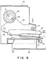
- Figure 9 is a side sectional view illustrating operation of the clinching mechanism.
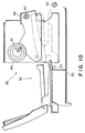
- Figure 10 is a side sectional view illustrating operation for loading the stapler.
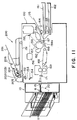
- Figure 11 is a front sectional view of a copying apparatus equipped with the sheet finisher shown in Figure 1.
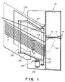
- Referring to Figures 1 and 2, a
sheet finisher 10 is in the form of a sorter provided with an automatic stapler and is coupled with a copying machine. Thesorter 10a has ten sheet discharge trays 11 which are vertically stacked. Each of the trays 11 haspins pins rotatable members rotatable members - A sheet is subjected to a copying operation by a copying machine (not shown) and is discharged through a
discharge passage 15, provided by top andbottom guide plates bottom discharging rollers - The structure of the
sorter 10a may be any of known structure, and therefore, the detailed description thereof is omitted. - The
automatic stapler 20 in thesorter 10a clinches thesheets rotatable members - Corresponding to the inclination of the sheet discharge tray 11a, the
automatic stapler 20 is also inclined (Figure 1). - As shown in Figure 2, the
automatic stapler 20 is disposed adjacent a lateral side at a front part of the tray 11. The non-stapling position thereof is determined so as not to obstruct the sheet discharge. Upon the clinching or stapling operation, thestapler 20 is moved to its clinching position A for clinching thesheets - Adjacent the opposite lateral side from the
automatic stapler 20, there is provided alateral aligning mechanism 22 for thesheets lateral shifting mechanism 22 is adapted for a plurality of sizes of the sheets and is effective to urge thesheets reference wall 23 so as to align thesheets - The lateral shifting or
aligning mechanism 22 has the following structure. It comprises arotatable shaft 24 which is rotatably supported at the top and bottom ends. Adjacent the top and bottom ends,swingable arms rotatable shaft 24. Between the other ends of theswingable arms bar 26 is extended. - Each of the trays 11 has an
arcuate opening 17 for permitting swinging movement of the lateral shiftingbar 26. Thelateral shifting bar 26 has a vertical length sufficient to be actable on the sheets on all of the trays 11. - To the bottom end of the
rotatable shaft 24, asector gear 27 is fixed. Thesector gear 27 is operatively connected with areversible motor 29 through areduction gear 28. By controlling the direction of rotation of thereversible motor 29, the lateral shifting lever 26 swings toward the center of the tray 11 to urge thesheets reference wall 23, thus aligning thesheets - Normally, the
lateral shifting mechanism 22 is operated in synchronism with the operation of theautomatic stapler 20, as will be described hereinbefore. However, it is operable during the sheet discharging to effect the aligning operation simultaneously with the sheet discharging. - The structure of the above-described
automatic stapler 20 will be described. - Referring to Figures 3 and 4, the
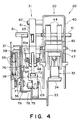
automatic stapler 20 has aclinching mechanisms 30 and amoving mechanism 31 which are juxtaposed with each other. Aslidable frame 33 carrying thestapler 32 bridges between themechanisms - The
stapler 32 comprises aclincher 32a, amagazine 32b for accommodating staples and ananvil 32c. Theclincher 32a is urged by an unshown spring to return to a position which is a predetermined distance away from theanvil 32c. Thestapler 32 is the one sold in a usual market as office equipment. - The
slidable frame 33 is small in size in a top plan view at the clinching mechanism side and is large in the moving mechanism side (Figure 3). It has a U-shaped cross-section (Figure 4). In a back side view, the side thereof adjacent theclinching mechanism 30 is low and horizontal. It has astapler supporting portion 34 as a bent portion. The moving mechanism side thereof is at a high level and is provided with four guidingrollers 35 at the inside (Figure 6). - The
stapler 32 is the one readily available in the market. Arear end 32d of thestapler 32 is engaged with amounting portion 34a of themounting portion 34, as shown in Figure 5. The front side of thestapler 32 is fixed on themounting portion 34 by ascrew 34b. Therefore, thestaple 32 is detachably mounted by thescrew 34b. - The
guide rollers 35 are engaged to upper andlower surfaces rail 37 fixed on a fixedframe 36 mounted on thesorter 10a. Thus, theslidable frame 33 is guided between the non-clinching position to the clinching position A and between the clinching portion A and an outside staple loading position. Aspring 39 is stretched between thefixed frame 36 and aslidable frame 33 to urge theslidable frame 33 to the loading position. - The
moving mechanism 31 is effective to move the slidable frame from the non-clinching position to the clinching position A, and thespring 39 moves themoving mechanism 31 from the non-stapling position to the loading position by releasing themoving mechanism 31 therefrom. - The structure of the
clinching mechanism 30 will be described. - Referring to Figures 3, 4 and 5, at an upper portion of a
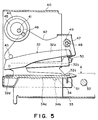
reverse U-shaped frame 40 fixed on thesorter 10a, adriving shaft 41 is rotatably supported and is extended out to themoving mechanism 31. Thedriving shaft 41 rotates through one full rotation by a motor through unshown reduction gears. - Below the
driving shaft 41, aclinching lever 42 is disposed which has a reverse U-shape at its front side, and is rotatably supported on the fixedframe 40 by apin 43 at its rear or base side. - To the driving
shaft 41, a pair ofeccentric cams 44 is fixed so as to be operatively contactable to the clinchinglever 42. The outside surface of therotatable cam 44 has acam groove 45 with which apin 46 planted in the clinchinglever 42 is engaged (Figure 5). - With this structure, when the
rotatable cam 44 rotates one full turn, thepin 46 is moved along thecam groove 45, so that the free end of the clinchinglever 42 makes one reciprocation in the vertical direction. - Adjacent the free end of the clinching
lever 42, a clinchingroller 47 is mounted. The clinchingroller 47 has ashaft 48 engaged withelongated slots 49 to permit vertical displacement of theroller 47. The shaft is urged down by astrong spring 50. Therefore, when the clinchinglever 42 is urged by extremely large pressure, the clinchingroller 47 retracts against thespring 50, thus avoiding application of extreme pressure. - The front end of the mounting
portion 34 for thestapler 32 is formed into atongue 51 which abuts astopper 52 fixed on the fixedframe 36 when thestapler 32 moves to the clinching position A, so that thestapler 32 is correctly positioned at the clinching position A. - The structure of the moving
mechanism 31 will be described. - Referring to Figures 3, 4 and 6, a generally heart mark shaped
cam 60 is fixed to an end of the drivingshaft 41. In the neighborhood of therotatable cam 60, the upper end portion of theswingable lever 61 is swingably supported on the fixedframe 40 by apin 62. - A
roller 63 is rotatably supported on theswingable lever 61, and theroller 63 is contactable to therotatable cam 60. Aspring 64 is engaged at one end to the fixedframe 40 and is engaged at the other end with theswingable lever 61, so that theswingable lever 61 is normally urged to therotatable cam 60 so as to establish a normal press-contact between theroller 63 and therotatable cam 60. - Therefore, when the
rotatable cam 60 is rotated one-full turn, theswingable lever 61 makes one reciprocation. - The bottom portion of the
swingable lever 61 has an urgingmember 65 rotatably supported by apin 66. The urgingmember 65 has anabutment part 67 at its upper front side so as to be contactable to the front surface 61a of theswingable lever 61 to urge it by aspring 68. - The urging
member 65 rotates against thespring 68 when theslidable frame 33 is extremely urged in the sliding direction. - At the top surface of the bottom portion of the
slidable frame 33, there is a contactinglever 69 at such a position as to face the above-described urgingmember 65. The middle portion of the contactinglever 69 is rotatably supported by apin 71 on a supportingmember 70 fixed on the top surface of the bottom portion of theslidable frame 33. On the rear portion thereof, aroller 72 contactable to the urgingmember 65 is rotatably supported. The bottom surface at the front side thereof is contacted to thestopper 73 extended from the supportingmember 70, so that the position of contact between theroller 72 and the urgingmember 65 is limited, wherein thespring 74 provides the urging force. - Therefore, when the
swingable lever 61 swings toward the front, the urgingmember 65 urges the contactinglever 69, so that theswingable frame 33 moves to the clinching position A. When theswingable lever 61 moves toward the rear, thespring 39 urging theslidable frame 33 retracts theswingable frame 33 to the retracted position. - Therefore, when the
swingable lever 61 makes one reciprocation in response to one rotation of therotatable cam 60, theslidable frame 33 makes one reciprocation movement. - When the
roller 72 of the contactinglever 69 is disengaged from the urgingmember 65, the slidingframe 33 is permitted to move to the staple loading position. - The sliding movement is effected by the urging force of the
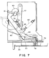
spring 39. In order to carry out the above described disengagement, the contactinglever 69 has a rotatably mounted releasingroller 75. Theroller 75 is operated by the releasinglever 76. - As shown in Figure 7, the bent portion of the releasing
lever 76 is rotatably mounted on the fixedframe 36 by apin 77, and the bottom portion is bent into acontactable part 78. Thecontactable part 78 is contactable to abent portion 79 of the fixedframe 36. It is urged by aspring 80 having an end fixed to the fixedframe 36. The upper part of the releasinglever 76 has an operatingpart 81. - When the operating
portion 81 of the releasinglever 76 is pressed down, thebottom contacting part 78 is raised into contact to a releasingroller 75 of the contactinglever 69, and by the rising of theroller 75, therear roller 72 is disengaged from the urgingpart 65. - When the contacting
lever 69 is returned to engagement with the urgingmember 65, theroller 72 of the contactinglever 69 is pressed down by an inclined guidingsurface 82 of the urgingmember 65 to permit the returning, at the time when theslidable frame 33 is urged. - Referring to Figure 11, an example of a copying machine equipped with the
sheet finisher 10 described in the foregoing, will be described. - The copying
machine 100 comprises an original supportingplaten glass 151, scanning mirrors 152, 153, 154 and 155 for folding the optical path for the light reflected by the original, avariable focus lens 156. It further comprises aphotosensitive drum 157, ahigh voltage unit 158, a developingdevice 159, animage transfer charger 159 and acleaning device 160. - The copying
machine 100 is provided with anupper cassette 161, abottom cassette 162,sheet feeding rollers registration roller 167. The sheet on which an image has been formed is conveyed to afixing device 169 along aconveyor belt 168 with the aid of a conveyingroller 171 and a sheet sensor 171a. The sheet may be manually fed from amanual tray 175. - The
photosensitive drum 157 rotates in the direction of an arrow in response to depression of a copy start key which will be described hereinafter. Then, thedrum 157 is rotated for a predetermined period of time, and the electric potential thereof is controlled. An original is illuminated by an illumination lamp not shown, and the light reflected from the original is imaged on thephotosensitive drum 157 by way of the scanning mirrors 152, 153, 154 and 155 and thelens 156. - The
photosensitive drum 157 has been charged by a corona charger supplied with the electric voltage from thehigh voltage source 158. The charged surface of thedrum 157 is exposed to the light image of the original through the mirrors and lenses and through a slit, so that an electrostatic latent image is formed on thephotosensitive drum 157. - The electrostatic latent image is developed by a developing
roller 159a of the developing device on thephotosensitive drum 157 into a toner image. The toner image is transferred onto a transfer sheet by thetransfer charger 159. - The sheets in the
upper cassette 161, thelower cassette 162 and the sheet deck 163 are fed out by thesheet feeding rollers registration roller 167, so that a loop of the sheet is formed. Theregistration roller 167 starts to feed the sheet at such a timing that a leading edge of the toner image formed on the rotatingphotosensitive drum 157 is aligned with the leading edge of the sheet. By the passage of the sheet between thephotosensitive drum 157 and thetransfer charger 159, the toner image is transferred from thephotosensitive drum 157 onto the transfer sheet. After the completion of the image transfer, the sheet is separated from thephotosensitive drum 157, and is conveyed on the conveyingbelt 168 to thefixing device 169, where the toner image is fixed thereon by heat and pressure. Then, the sheet is discharged from the apparatus by the feedingrollers 171. - The
photosensitive drum 157 after the image transfer continues its rotation, so that the surface thereof is cleaned by thecleaning device 160. - The copying apparatus is equipped with an automatic
original feeder 200, which comprises a stackingtray 201 for stacking the originals,sensors sensors sensor 203 is at the rear side. - If the number of sensors is increased, a larger number of lateral sizes can be detected. The longitudinal dimension of the original is discriminated on the basis of time duration in which the
sensor - The original fed from the stacking
tray 201 to the original supportingplaten 151 along thesheet path 204 is stacked again on thetray 201 through thesheet passage 205. - The description will now be made as to the clinching operation of the
automatic stapler 20. When the copying machine is discharging thecopy sheets stapler 20 does not obstruct the sheet discharging action. - In the retracted state, the
clinching mechanism 30 and the movingmechanism 31 are also at the retracted positions, shown in Figures 3, 5 and 6. - After the completion of a predetermined amount of copying operations by the copying machine, and when the automatic stapling mode is selected, the
lateral shifting mechanism 22 operates at the initial stage of the operation in that mode to align all of thesheets - In this operation, by rotating the
reversible motor 29 in the forward and backward directions through predetermined amounts, the lateral shifting or aligningbar 26 makes one reciprocation, by which thesheets reference wall 23 adjacent the clinching position A so that thesheets - The driving
shaft 41 is rotated one-full turn to effect the clinching operation. First, in the movingmechanism 31, therotatable cam 60 shown in Figure 6 starts to rotate. About 60 degrees of the rotational position, the reciprocal movement of theswingable lever 61 is completed. By the reciprocal movement, the urgingmember 65 of theswingable lever 61 pushes the contactinglever 69 out. Therefore, as shown in Figure 8, theslidable frame 33 is moved to the clinching position, and thetongue 51 of the mountingportion 34 of theswingable frame 33 is contacted to thestopper 52, by which the position thereof is limited (Figure 9). - By this movement of the
slidable frame 33, the clinching position A of thesheets stapler 32. - This state is maintained from the initial stage of the rotation of the
cam 60 to the angular position thereof of about 300 degrees. - In the clinching mechanism, the
eccentric rotatable cam 44 starts to rotate from the position shown in Figure 5 to lower the clinchinglever 42. At thecam 44 angular position of about 70 degrees, the clinchingroller 47 is contacted to the top surface of thestapler 32. With further rotation, the forward (downward) movement of the clinchinglever 42 is completed by approximately 180 degrees rotation from the start of the rotation. By the forward movement, the clinchingroller 47 presses thestapler 32 at its top part. As shown in Figure 9, thesheets - With further rotation of the rotating
cam 44, the clinchinglever 42 moves upwardly, by which the stapler is released. At about 290 degrees position from the start of the rotation, the clinchingroller 47 is disengaged from the top surface of thestapler 32. Upon completion of one-full turn, it is returned to the retracted position shown in Figure 5. - At the position of about 30 degrees from the start of the rotation of the
cam 60 in the movingmechanism 31, the backward movement of theswingable lever 61 is permitted. Upon completion of one-full rotation, it is returned to the retracted position shown in Figure 6. - The description will be made as to the loading operation for the
stapler 32. - As shown in Figure 7, when the operating
portion 81 of the releasinglever 76 is depressed, thecontact portion 78 thereof raises the releasingroller 75 of the contactinglever 69, and therefore, theroller 72 at the rear side of the contactinglever 69 is disengaged from the urgingmember 65 of theswingable lever 61. - As a result, the
slidable frame 33 is permitted to move from the retracted position to the loading position by thespring 39. As shown in Figure 10, thestapler 32 is drawn out. Then, the upper part is opened, so that the staples can be loaded. - After the stapler is loaded with the staples, the
slidable frame 33 is manually urged toward inside. Then, theroller 72 of the contactinglever 69 is lowered by the inclined guidingsurface 82 of thepressing part 65 of theswingable lever 61. It is then locked at the front side of thepressing portion 65, so that it can be restored to the retracted position. - According to the
automatic stapler 20 of this embodiment described in the foregoing, thestapler 32 is mounted on the mountingportion 34 of theslidable frame 33. Thestapler 32 is the one readily available in the market as office equipment. Therefore, the cost is very low. When thestapler 32 is damaged, thestapler 32 may be replaced with new one, and therefore, the maintenance is easy. - The
rotatable cams driving shaft 41 to move theslidable frame 33 and the clinchinglever 42, and therefore, the structure is simplified, and the height of the structure is reduced, thus minimizing the size of the device. - While the invention has been described with reference to the structures disclosed herein, it is not confined to the details set forth and this application is intended to cover such modifications or changes as may come within the scope of the following claims.
Claims (10)
- A sheet finisher apparatus, comprising:
sheet supporting means (11) for supporting a stack of sheets;
stapling means (32) for stapling the stack of sheets supported by said supporting means; said stapling means (32) being movable between a first position (A) for stapling the sheets and a second position where said stapling means (32) do not obstruct the sheet discharging action;
moving means (31) for moving said stapling means (32) between said first and second positions;
characterized in that
said stapling means (32) is additionally movable from said second position to a third position by releasing said stapling means (32) from said moving means (31) at said second position,
said third position allowing the stapling means (32) to be subjected to its maintenance operation. - An apparatus according to Claim 1, wherein the stapling means (32) is detachable at the third position.
- An apparatus according to Claim 1, wherein at the third position, the stapling means (32) is loadable with staples.
- An apparatus according to claim 1, further comprising locking means for disabling moving of the stapling means (32) and releasing means (75) for releasing the locking means.
- An apparatus according to Claim 4, wherein releasing means (75) is manually operable.
- An apparatus according to Claim 1, wherein the supporting means includes plural trays (11) for supporting stacks of the sheets and tray moving means for moving the trays (11) supporting the sheets to be stapled to the stapling position.
- An apparatus according to Claim 1, wherein said moving means (31) includes a swingable lever (61) which is swingable by the driving source (41), wherein said stapling means (32) is moved between the first position and the second position by swinging movement of the swingable lever (61).
- An apparatus according to Claim 1, wherein said supporting means is provided with aligning means (22) for aligning the sheets thereon prior to the stapling operation of said stapling means (32).
- An apparatus according to Claim 8, wherein the aligning means (22) is provided with a reference stopper (52) adjacent the stapling position and an urging bar for abutting the sheets to the reference stopper (52).
- An image forming apparatus, comprising:
an image forming means (100) for forming an image onto a sheet; and
a sheet finisher apparatus according to any one of preceding claims.
Priority Applications (1)
| Application Number | Priority Date | Filing Date | Title |
|---|---|---|---|
| EP93119230A EP0589493B1 (en) | 1990-05-23 | 1991-05-22 | A sheet finisher |
Applications Claiming Priority (2)
| Application Number | Priority Date | Filing Date | Title |
|---|---|---|---|
| JP132797/90 | 1990-05-23 | ||
| JP2132797A JP2783649B2 (en) | 1990-05-23 | 1990-05-23 | Automatic stapler for copier |
Related Child Applications (1)
| Application Number | Title | Priority Date | Filing Date |
|---|---|---|---|
| EP93119230.6 Division-Into | 1993-11-29 |
Publications (2)
| Publication Number | Publication Date |
|---|---|
| EP0458317A1 EP0458317A1 (en) | 1991-11-27 |
| EP0458317B1 true EP0458317B1 (en) | 1995-11-02 |
Family
ID=15089791
Family Applications (2)
| Application Number | Title | Priority Date | Filing Date |
|---|---|---|---|
| EP91108323A Expired - Lifetime EP0458317B1 (en) | 1990-05-23 | 1991-05-22 | A sheet finisher |
| EP93119230A Expired - Lifetime EP0589493B1 (en) | 1990-05-23 | 1991-05-22 | A sheet finisher |
Family Applications After (1)
| Application Number | Title | Priority Date | Filing Date |
|---|---|---|---|
| EP93119230A Expired - Lifetime EP0589493B1 (en) | 1990-05-23 | 1991-05-22 | A sheet finisher |
Country Status (4)
| Country | Link |
|---|---|
| EP (2) | EP0458317B1 (en) |
| JP (1) | JP2783649B2 (en) |
| KR (1) | KR970001196B1 (en) |
| DE (2) | DE69114182T2 (en) |
Families Citing this family (4)
| Publication number | Priority date | Publication date | Assignee | Title |
|---|---|---|---|---|
| KR101073403B1 (en) | 2004-09-09 | 2011-10-17 | 엘지디스플레이 주식회사 | Liquid crystal display device and method of fabricating thereof |
| KR101066489B1 (en) | 2004-11-12 | 2011-09-21 | 엘지디스플레이 주식회사 | Poly-type thin film transistor substrate and manufacturing method thereof |
| KR101192746B1 (en) | 2004-11-12 | 2012-10-18 | 엘지디스플레이 주식회사 | Method of Fabricating Thin Film Transistor Substrate of Poly-type |
| CN117584651A (en) * | 2023-12-05 | 2024-02-23 | 广西壮族自治区水产科学研究院 | Financial binding device and binding method for financial offices |
Family Cites Families (3)
| Publication number | Priority date | Publication date | Assignee | Title |
|---|---|---|---|---|
| US4313670A (en) * | 1979-10-30 | 1982-02-02 | Xerox Corporation | Reproduction machine with a pivotal stapling device |
| DE3304875C2 (en) * | 1983-02-12 | 1986-10-23 | Agfa-Gevaert Ag, 5090 Leverkusen | Copy filing table |
| DE3577824D1 (en) * | 1985-04-23 | 1990-06-28 | Xerox Corp | Blaettersortierer. |
-
1990
- 1990-05-23 JP JP2132797A patent/JP2783649B2/en not_active Expired - Fee Related
-
1991
- 1991-05-22 EP EP91108323A patent/EP0458317B1/en not_active Expired - Lifetime
- 1991-05-22 DE DE69114182T patent/DE69114182T2/en not_active Expired - Lifetime
- 1991-05-22 EP EP93119230A patent/EP0589493B1/en not_active Expired - Lifetime
- 1991-05-22 DE DE69123061T patent/DE69123061T2/en not_active Expired - Fee Related
- 1991-05-23 KR KR1019910008396A patent/KR970001196B1/en not_active Expired - Fee Related
Also Published As
| Publication number | Publication date |
|---|---|
| JPH0427592A (en) | 1992-01-30 |
| DE69123061T2 (en) | 1997-03-20 |
| EP0458317A1 (en) | 1991-11-27 |
| DE69114182D1 (en) | 1995-12-07 |
| KR970001196B1 (en) | 1997-01-29 |
| JP2783649B2 (en) | 1998-08-06 |
| DE69123061D1 (en) | 1996-12-12 |
| EP0589493B1 (en) | 1996-11-06 |
| EP0589493A1 (en) | 1994-03-30 |
| DE69114182T2 (en) | 1996-04-18 |
| KR910020511A (en) | 1991-12-20 |
Similar Documents
| Publication | Publication Date | Title |
|---|---|---|
| JP4379561B2 (en) | Sheet processing apparatus and image forming apparatus having the same | |
| JP3639737B2 (en) | Sheet processing apparatus and image apparatus provided with sheet alignment rotating body | |
| EP0371403B1 (en) | A sheet post-processing apparatus and image forming apparatus | |
| US5137265A (en) | Sheet post-processing apparatus | |
| JPH0667675B2 (en) | Copier equipped with paper stapler device | |
| US6773005B2 (en) | Sheet post-processing apparatus with fixed and auxiliary guide members | |
| US5374043A (en) | Sorter with stapler actived release gate mechanism | |
| US6607188B2 (en) | Sheet post-processing apparatus | |
| EP0458317B1 (en) | A sheet finisher | |
| US5279494A (en) | Sheet finisher with standard type stapler | |
| JP4329918B2 (en) | Sheet processing apparatus and image forming apparatus having the same | |
| JP3877510B2 (en) | Paper discharge device for image forming apparatus | |
| US11274010B2 (en) | Sheet post-processing apparatus and image forming system equipped with same | |
| JP4302280B2 (en) | Folded sheet stacking apparatus and image forming apparatus equipped with the apparatus | |
| JP2703282B2 (en) | Image forming device | |
| JP2780787B2 (en) | Image forming device | |
| JP2780804B2 (en) | Image forming device | |
| JP2758195B2 (en) | Sorter with stapler | |
| JP2912378B2 (en) | Sorter with stapler | |
| JP2860837B2 (en) | Sorter with stapler device | |
| JP2680109B2 (en) | Sorter with stapler | |
| JP2680108B2 (en) | Post-processing device for image forming apparatus | |
| JP2638882B2 (en) | Paper storage device | |
| JP2920425B2 (en) | Sorter with stapler device | |
| JPH0223154A (en) | After-treatment device for image bearing sheet |
Legal Events
| Date | Code | Title | Description |
|---|---|---|---|
| PUAI | Public reference made under article 153(3) epc to a published international application that has entered the european phase |
Free format text: ORIGINAL CODE: 0009012 |
|
| 17P | Request for examination filed |
Effective date: 19910621 |
|
| AK | Designated contracting states |
Kind code of ref document: A1 Designated state(s): DE FR GB IT |
|
| 17Q | First examination report despatched |
Effective date: 19920526 |
|
| GRAA | (expected) grant |
Free format text: ORIGINAL CODE: 0009210 |
|
| AK | Designated contracting states |
Kind code of ref document: B1 Designated state(s): DE FR GB IT |
|
| XX | Miscellaneous (additional remarks) |
Free format text: TEILANMELDUNG 93119230.6 EINGEREICHT AM 22/05/91. |
|
| REF | Corresponds to: |
Ref document number: 69114182 Country of ref document: DE Date of ref document: 19951207 |
|
| ITF | It: translation for a ep patent filed | ||
| ET | Fr: translation filed | ||
| PLBE | No opposition filed within time limit |
Free format text: ORIGINAL CODE: 0009261 |
|
| STAA | Information on the status of an ep patent application or granted ep patent |
Free format text: STATUS: NO OPPOSITION FILED WITHIN TIME LIMIT |
|
| 26N | No opposition filed | ||
| REG | Reference to a national code |
Ref country code: GB Ref legal event code: IF02 |
|
| PGFP | Annual fee paid to national office [announced via postgrant information from national office to epo] |
Ref country code: GB Payment date: 20100324 Year of fee payment: 20 |
|
| PGFP | Annual fee paid to national office [announced via postgrant information from national office to epo] |
Ref country code: FR Payment date: 20100603 Year of fee payment: 20 |
|
| PGFP | Annual fee paid to national office [announced via postgrant information from national office to epo] |
Ref country code: IT Payment date: 20100525 Year of fee payment: 20 Ref country code: DE Payment date: 20100531 Year of fee payment: 20 |
|
| REG | Reference to a national code |
Ref country code: DE Ref legal event code: R071 Ref document number: 69114182 Country of ref document: DE |
|
| REG | Reference to a national code |
Ref country code: GB Ref legal event code: PE20 Expiry date: 20110521 |
|
| PG25 | Lapsed in a contracting state [announced via postgrant information from national office to epo] |
Ref country code: GB Free format text: LAPSE BECAUSE OF EXPIRATION OF PROTECTION Effective date: 20110521 |
|
| PG25 | Lapsed in a contracting state [announced via postgrant information from national office to epo] |
Ref country code: DE Free format text: LAPSE BECAUSE OF EXPIRATION OF PROTECTION Effective date: 20110523 |