EP0458090A2 - Device for the treatment of contaminated soils by a gas - Google Patents
Device for the treatment of contaminated soils by a gas Download PDFInfo
- Publication number
- EP0458090A2 EP0458090A2 EP91106944A EP91106944A EP0458090A2 EP 0458090 A2 EP0458090 A2 EP 0458090A2 EP 91106944 A EP91106944 A EP 91106944A EP 91106944 A EP91106944 A EP 91106944A EP 0458090 A2 EP0458090 A2 EP 0458090A2
- Authority
- EP
- European Patent Office
- Prior art keywords
- gas
- shaft
- arrangement according
- wall
- gas flow
- Prior art date
- Legal status (The legal status is an assumption and is not a legal conclusion. Google has not performed a legal analysis and makes no representation as to the accuracy of the status listed.)
- Granted
Links
- 239000002689 soil Substances 0.000 title claims abstract description 32
- 238000011282 treatment Methods 0.000 title claims description 6
- 239000000126 substance Substances 0.000 claims abstract description 5
- 238000007789 sealing Methods 0.000 claims description 7
- 239000007788 liquid Substances 0.000 claims description 6
- 239000004744 fabric Substances 0.000 claims description 5
- 238000010438 heat treatment Methods 0.000 claims description 3
- 239000000463 material Substances 0.000 claims 1
- 230000002441 reversible effect Effects 0.000 claims 1
- 239000000356 contaminant Substances 0.000 abstract description 7
- 238000011065 in-situ storage Methods 0.000 abstract 1
- 239000007789 gas Substances 0.000 description 51
- 238000004140 cleaning Methods 0.000 description 3
- 239000012535 impurity Substances 0.000 description 3
- 238000000034 method Methods 0.000 description 3
- 230000002925 chemical effect Effects 0.000 description 2
- XLYOFNOQVPJJNP-UHFFFAOYSA-N water Substances O XLYOFNOQVPJJNP-UHFFFAOYSA-N 0.000 description 2
- OKTJSMMVPCPJKN-UHFFFAOYSA-N Carbon Chemical compound [C] OKTJSMMVPCPJKN-UHFFFAOYSA-N 0.000 description 1
- 230000015572 biosynthetic process Effects 0.000 description 1
- 229910052799 carbon Inorganic materials 0.000 description 1
- 239000012159 carrier gas Substances 0.000 description 1
- 230000000694 effects Effects 0.000 description 1
- 238000005265 energy consumption Methods 0.000 description 1
- 239000003673 groundwater Substances 0.000 description 1
- 239000002920 hazardous waste Substances 0.000 description 1
- 230000007774 longterm Effects 0.000 description 1
- 230000001105 regulatory effect Effects 0.000 description 1
Images
Classifications
-
- B—PERFORMING OPERATIONS; TRANSPORTING
- B09—DISPOSAL OF SOLID WASTE; RECLAMATION OF CONTAMINATED SOIL
- B09C—RECLAMATION OF CONTAMINATED SOIL
- B09C1/00—Reclamation of contaminated soil
- B09C1/08—Reclamation of contaminated soil chemically
-
- B—PERFORMING OPERATIONS; TRANSPORTING
- B09—DISPOSAL OF SOLID WASTE; RECLAMATION OF CONTAMINATED SOIL
- B09C—RECLAMATION OF CONTAMINATED SOIL
- B09C1/00—Reclamation of contaminated soil
- B09C1/005—Extraction of vapours or gases using vacuum or venting
-
- E—FIXED CONSTRUCTIONS
- E21—EARTH DRILLING; MINING
- E21B—EARTH DRILLING, e.g. DEEP DRILLING; OBTAINING OIL, GAS, WATER, SOLUBLE OR MELTABLE MATERIALS OR A SLURRY OF MINERALS FROM WELLS
- E21B43/00—Methods or apparatus for obtaining oil, gas, water, soluble or meltable materials or a slurry of minerals from wells
- E21B43/02—Subsoil filtering
- E21B43/08—Screens or liners
- E21B43/082—Screens comprising porous materials, e.g. prepacked screens
Definitions
- the invention relates to an arrangement for gas treatment of contaminated soil on the spot, with a well that is well gas-permeable at least partially gas-permeable to the shaft wall.
- the invention has for its object to provide an arrangement of the type mentioned so that it can be used to clean contaminated soil with little energy and space-saving.
- a section with a gas-impermeable shaft wall is formed in the shaft at a distance from the tightly closable shaft opening, which section lies between two shaft sections with a gas-permeable wall, that a gas delivery device for generating a gas circulation flow in the shaft and in the ground it is provided that at least one device for influencing the strength of the gas flow in the shaft depending on the Density of the soil is provided to achieve and maintain a laminar gas flow in the soil and that elements which change the composition of the gas flow are arranged in at least one of the shaft sections with a gas-permeable wall.
- the gas conveying device for generating the gas circulation flow can be arranged both in the shaft in the section with gas-impermeable shaft wall and outside the shaft.
- the gas delivery device can be provided with further filter devices and connected to the two gas-permeable regions of the shaft via concentrically guided pipes be.
- the direction of the gas circulation flow generated by the conveying device can be reversed at any time by simply switching the gas conveying device.
- the device for influencing the strength of the gas flow in the shaft can be a control or regulating device which changes the power consumption of the gas delivery device, for example the speed of a radial fan used as a gas delivery device. Automatic control is also possible, depending, for example, on the flow strength in the shaft or the pressure distribution in the shaft.
- the device can also be designed as a pure gas flow braking device. Such a braking device does not have to be adjustable, for example in the manner of an aperture. There is a uniform soil density at many locations, which allows the use of an unadjustable gas flow resistance.
- a predetermined gas flow resistance can be achieved according to the invention, for example, in that the gas passage resistance in the areas of the gas-permeable wall is determined by an appropriate choice or design of these wall areas.
- the elements for changing the composition of the gas flow in the arrangement designed according to the invention not only have to be the usual gas filters which absorb gaseous impurities, but can also, alone or in addition, be devices for releasing substances into the gas flow or a partial gas flow which have a chemical effect on the Have contaminants in the ground.
- a pipe insert is interchangeably arranged in the shaft, which has sieve walls on both sides of a closed-walled pipe section containing the gas delivery device and whose closed-walled pipe section can be sealed off from the shaft wall by means of at least one outer sealing collar.
- the tube insert can be provided with a liquid collecting trough at its lower end.
- the gas-permeable sieve walls of the tube insert can expediently consist of sieve cloth webs which are wound screw-like over support rods or webs of the tube insert parallel to the tube axis.
- the screen cloth webs can be single or multi-layer, butt-jointed or wound with overlapping edges.
- the forward resistance of these wall areas for the gas flow can be set by the number of layers or the thickness of the overlap areas.
- the furnishing parts for the arrangement can be manufactured inexpensively.
- the whole arrangement requires little space, since additional air flow ducts are omitted.
- the arrangement can be used anywhere, even in built-up areas, where a largely gas-tight covering of the soil area to be cleaned can be ensured.
- the method operated with the arrangement designed according to the invention with laminar gas flow can be carried out with gas delivery devices with low energy consumption, so that long-term soil treatments can also be carried out economically with this arrangement, even if additional heating devices are used Increase the effectiveness of the gas used and the elements that change the composition of the gas flow or to influence the pressure differences occurring in the shaft.
- this pipe insert can be removed at regular intervals for cleaning and for replacing or reactivating the elements used to influence the composition of the gas flow.
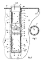
- Fig. 1 shows a shaft bore 10 with the shaft wall 11, which has been brought down in a contaminated, groundwater-free soil 12.
- a pipe insert 13 is interchangeably arranged in the shaft and is divided into several pipe sections over its length. At its upper end, which can be closed gas-tight by a cover 14 At the end, it has an end section 13.1 with a gas-impermeable tube wall.
- a gas-impermeable tube wall also has a central tube section 13.2 and an inner end section 13.3, which is closed with an end wall 16 to form a liquid collecting trough 15.
- a first or upper pipe section 13.4 with a gas-permeable screen wall is formed between the upper end section 13.1 and the middle pipe section 13.2 of the pipe insert 13.
- a pipe section 13.5 also provided with a gas-permeable screen wall, is located between the middle pipe section 13.2 and the lower end section 13.3 of the pipe insert 13.
- the screen walls of the pipe sections 13.4 and 13.5 can be formed from webs of woven screen cloths 17, which according to FIG. 2 are wound onto support webs 18 parallel to the pipe axis, which form a connection between the closed-walled pipe sections 13.1-13.3.
- the woven screen cloth webs 17 can also be wound in multiple layers or overlap one another with their edge regions.
- the space 19 existing between the tube insert 13 and the shaft wall 11 is bridged and interrupted in the areas of the closed-walled tube sections 13.1-13.3 by annular sealing sleeves 20.
- the sealing sleeves 20 can be inflatable sealing sleeves after the tube insert has been introduced into the shaft bore 10.
- the area of the soil 12 to be cleaned with the arrangement is covered around the shaft bore 10 with a gas-tight film 21 which is close to the upper end section 13.1 of the pipe insert 13 connects and the outer edge 21.1 is tightly embedded in the soil 12.
- a radial fan 22 is arranged in the interior of the central closed-walled tube section 13.2 as a gas delivery device, together with its electric drive motor 23 and with a control device 24 influencing its speed. Its electrical connection cable 25 is guided together with the connection cable 26 for an electrical heating device 27 also arranged in the pipe section 13.2 in a gas-tight manner through the cover 14 of the pipe insert to the outside.
- the control device 24 is provided with a flow sensor 28.
- the radial fan 22 generates a gas flow directed from top to bottom in the tube insert 13.
- the sieve wall of the upper gas-permeable pipe section 13.4 is provided on the inside with a gas filter jacket 29.
- a gas filter jacket 29 Such an inner gas filter jacket can also be arranged in the lower gas-permeable pipe section 13.5, as indicated by dash-dotted lines.
- an outer support 30 is also indicated on the screen wall with dash-dotted lines. It is a gas-permeable pad 30, which contains substances intended for delivery to the gas stream, which have a chemical effect on the impurities contained in the soil.
- the laminar gas circulation flow forced from the shaft bore 10 into the soil 12 and back by means of the radial fan 23 is indicated by arrows 31. Leachate arising in the tube insert 13 can be sucked out of the liquid collecting trough 15 by means of a submersible pump 32 if necessary.
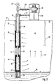
- FIG. 3 shows a second embodiment of an arrangement according to the invention.
- a shaft wall 10 'closed off from the outside by a cover 21' two mutually separated shaft regions 33 and 34 are formed by sealing sleeves 20 ', in which the shaft wall is designed to be gas-permeable.
- Double-jacket filters 35 and 36 which are surrounded by filter gravel 37, are arranged within these regions 33 and 34.
- the shaft 10 ' is closed with a pot insert 15' serving as a liquid collecting container, which is arranged below the groundwater level 38.
- a fan 39 to which a water separator 40 is connected, is arranged above the surface of the earth.
- the fan 39 is connected via two connecting pipes 41, 42 to pipes 43, 44 arranged concentrically in the manhole, the outer pipe 43 reaching as far as the gas-permeable manhole area 33 and used to extract the contaminated gas.
- the inner tube 44 is led to the lower gas-permeable shaft area 34 and is used to introduce gas that can escape into the soil 12.
- a water suction pipe 32 ' is also arranged inside the inner pipe 44, which is connected to a pump 45 arranged outside the shaft 10 and serves to suck off liquid from the pot insert 15'.
- a bore 46 is made in the soil 12 for pressure equalization.
- the velocity of the gas flow 31 ' can be influenced by a corresponding filling of the double jacket filters 35, 36.
- filters 35, 36 There are also other devices on the surface of the earth, such as carbon filters or a switchover device for reversing the direction of the gas circulation flow.
- the gas is pressed into the upper shaft area 33 and sucked off again in the lower area 34.
Abstract
Description
Die Erfindung betrifft eine Anordnung zur Gasbehandlung von verunreinigtem Erdreich an Ort und Stelle, mit einem in das in diesem Bereich gasdicht abgedeckte Erdreich getriebenen Schacht gut mindestens teilweise gasdurchlässiger Schachtwandung.The invention relates to an arrangement for gas treatment of contaminated soil on the spot, with a well that is well gas-permeable at least partially gas-permeable to the shaft wall.
Zum Austreiben leichtflüchtiger Verunreinigungen aus dem Erdreich ist bereits vorgeschlagen worden, in einem in das verunreinigte Erdreich getriebenen Schacht mit gasdurchlässiger Schachtwandung durch Absaugen von Luft einen Unterdruck zu erzeugen, so daß Luft zusammen mit den flüchtigen Verunreinigungen aus dem Erdreich in den Schacht nachströmt und aus dem Schacht zu einer Filtereinrichtung abgesaugt werden kann. Durch im Umkreis eingebrachte zusätzliche Bohrungen kann dabei das Nachfließen von Luft in das verunreinigte Erdreich begünstigt werden (DE-OS 37 29 299). Mit dem genannten Verfahren werden hervorragende Ergebnisse erzielt.For expelling volatile contaminants from the ground, it has already been proposed to create a negative pressure in a shaft driven into the contaminated ground with a gas-permeable shaft wall by suctioning off air, so that air flows in together with the volatile contaminants from the ground into the shaft and out of the Shaft can be suctioned off to a filter device. The additional flow can be caused by additional holes drilled in the area be favored by air into the contaminated soil (DE-OS 37 29 299). Excellent results are achieved with the aforementioned method.
Schwieriger und aufwendiger gestaltet sich die Reinigung von verunreinigtem Erdreich, wenn die Verunreinigungen überwiegend durch schwerlösliche Stoffe verursacht sind. Hier wird derzeit das verunreinigte Erdreich abgetragen und durch Ausbrennen der Verunreinigungen in Durchlauföfen entfernt, oder das abgetragene Erdreich wird auf Sondermülldeponien abgelagert. Dieses Verfahren ist mit sehr hohen Kosten verbunden und läßt sich nur begrenzt und in unbebautem Gelände anwenden. Hier haben aber Vorversuche gezeigt, daß es möglich ist, auch bei einem höheren Anteil von schwerflüchtigen Verunreinigungen eine Reinigung des Erdreichs an Ort und Stelle, wenn auch erst über einen längeren Behandlungszeitraum, zu erreichen.Cleaning contaminated soil is more difficult and complex if the contaminants are mainly caused by poorly soluble substances. Here the contaminated soil is currently being removed and removed by burning the contaminants in continuous furnaces, or the removed soil is being deposited in hazardous waste landfills. This method is associated with very high costs and can only be used to a limited extent and in undeveloped terrain. Here, however, preliminary tests have shown that it is possible to clean the soil on the spot, even if there is a higher proportion of less volatile impurities, even if only over a longer treatment period.
Der Erfindung liegt die Aufgabe zugrunde, eine Anordnung der eingangs genannten Art so auszubilden, daß mit ihrer Hilfe mit geringem Energieaufwand und raumsparend eine Reinigung verunreinigten Erdreiches erreicht werden kann.The invention has for its object to provide an arrangement of the type mentioned so that it can be used to clean contaminated soil with little energy and space-saving.
Die gestellte Aufgabe wird mit dieser Anordnung erfindungsgemäß dadurch gelöst, daß im Schacht mit Abstand von der dicht verschließbaren Schachtöffnung ein Abschnitt mit gasundurchlässiger Schachtwandung gebildet ist, der zwischen zwei Schachtabschnitten mit gasdurchlässiger Wandung liegt, daß eine Gasfördervorrichtung zur Erzeugung einer Gasumlaufströmung im Schacht und im Erdreich vorgesehen ist, daß mindestens eine Vorrichtung zur Beeinflussung der Stärke der Gasströmung im Schacht in Abhängigkeit von der Dichte des Erdreiches zur Erzielung und Beibehaltung einer laminaren Gasströmung im Erdreich vorgesehen ist und daß mindestens in einem der Schachtabschnitte mit gasdurchlässiger Wandung die Zusammensetzung des Gasstromes verändernde Elemente angeordnet sind.The object is achieved with this arrangement according to the invention in that a section with a gas-impermeable shaft wall is formed in the shaft at a distance from the tightly closable shaft opening, which section lies between two shaft sections with a gas-permeable wall, that a gas delivery device for generating a gas circulation flow in the shaft and in the ground it is provided that at least one device for influencing the strength of the gas flow in the shaft depending on the Density of the soil is provided to achieve and maintain a laminar gas flow in the soil and that elements which change the composition of the gas flow are arranged in at least one of the shaft sections with a gas-permeable wall.
In den meisten Einsatzfällen genügt Luft zur Bildung des Gasstromes. In den Schacht kann aber auch ein besonderes Behandlungsgas oder Trägergas eingebracht werden. In jedem Falle ist für den Wirkungsgrad der Anordnung entscheidend, daß die Gasströmung in den Bereichen des Gasaustritts und des Gaseintritts in den Schacht so eingestellt ist, daß das Gas auf seinem Weg durch das verunreinigte Erdreich eine laminare Strömung beibehalten kann. Bei dieser Einstellung der Gasströmung muß die Dichte des verunreinigten Erdreiches berücksichtigt werden. Wird durch einen zu starken Druck ein Abriß der laminaren Gasströmung und eine Wirbelbildung verursacht, wird die wichtige gleichmäßige Einwirkung des Gases auf das Erdreich empfindlich gestört. Außerdem muß zur Erzielung und Aufrechterhaltung einer turbulenten Gasströmung durch das Erdreich ein wesentlich höherer Energieaufwand getrieben werden, der bei der auch noch verschlechterten Reinigungswirkung die Wirtschaftlichkeit der Anordnung in Frage stellen würde.In most applications, air is sufficient to form the gas flow. However, a special treatment gas or carrier gas can also be introduced into the shaft. In any case, it is decisive for the efficiency of the arrangement that the gas flow in the areas of the gas outlet and the gas inlet into the shaft is set such that the gas can maintain a laminar flow on its way through the contaminated soil. When adjusting the gas flow, the density of the contaminated soil must be taken into account. If the laminar gas flow is interrupted by excessive pressure and the formation of vortices, the important, even impact of the gas on the soil is severely disturbed. In addition, in order to achieve and maintain a turbulent gas flow through the soil, a much higher expenditure of energy must be driven, which would also jeopardize the economy of the arrangement given the still worsening cleaning effect.
Die Gasfördervorrichtung zur Erzeugung der Gasumlaufströmung kann sowohl im Schacht im Abschnitt mit gasundurchlässiger Schachtwandung als auch außerhalb des Schachtes angeordnet sein. Bei Anordnung außerhalb des Schachtes kann die Gasfördervorrichtung mit weiteren Filtereinrichtungen versehen und über konzentrisch geführte Rohre mit den beiden gasdurchlässigen Bereichen des Schachtes verbunden sein. Die Richtung der durch die Fördervorrichtung erzeugten Gasumlaufströmung ist durch einfaches Umschalten der Gasfördervorrichtung jederzeit umkehrbar.The gas conveying device for generating the gas circulation flow can be arranged both in the shaft in the section with gas-impermeable shaft wall and outside the shaft. When arranged outside the shaft, the gas delivery device can be provided with further filter devices and connected to the two gas-permeable regions of the shaft via concentrically guided pipes be. The direction of the gas circulation flow generated by the conveying device can be reversed at any time by simply switching the gas conveying device.
Die Vorrichtung zur Beeinflussung der Stärke der Gasströmung im Schacht kann eine Steuer- oder Regelvorrichtung sein, welche die Leistungsaufnahme der Gasfördervorrichtung verändert, beispielsweise die Drehzahl eines als Gasfördervorrichtung verwendeten Radialventilators. Hierbei ist auch eine automatische Regelung, abhängig beispielsweise von der Strömungsstärke im Schacht oder der Druckverteilung im Schacht, möglich. Die Vorrichtung kann aber auch als reine Gasstrom-Bremsvorrichtung ausgebildet sein. Eine solche Bremsvorrichtung muß nicht, beispielsweise nach Art einer Blende, verstellbar sein. An vielen Einsatzstellen ist eine gleichmäßige Bodendichte vorhanden, die den Einsatz eines unverstellbaren Gasströmungswiderstandes erlaubt. Ein solcher vorgegebener Gasströmungswiderstand läßt sich beispielsweise erfindungsgemäß dadurch erzielen, daß der Gasdurchtrittswiderstand in den Bereichen der gasdurchlässigen Wandung durch eine entsprechende Wahl oder Ausbildung dieser Wandungsbereiche festgelegt wird.The device for influencing the strength of the gas flow in the shaft can be a control or regulating device which changes the power consumption of the gas delivery device, for example the speed of a radial fan used as a gas delivery device. Automatic control is also possible, depending, for example, on the flow strength in the shaft or the pressure distribution in the shaft. The device can also be designed as a pure gas flow braking device. Such a braking device does not have to be adjustable, for example in the manner of an aperture. There is a uniform soil density at many locations, which allows the use of an unadjustable gas flow resistance. Such a predetermined gas flow resistance can be achieved according to the invention, for example, in that the gas passage resistance in the areas of the gas-permeable wall is determined by an appropriate choice or design of these wall areas.
Die Elemente zur Veränderung der Zusammensetzung des Gasstromes müssen bei der erfindungsgemäß ausgebildeten Anordnung nicht nur die üblichen, gasförmige Verunreinigungen aufnehmenden Gasfilter sein, sondern können auch allein oder zusätzlich Vorrichtungen zur Abgabe von Stoffen in den Gasstrom oder einen Gasteilstrom sein, die eine chemische Einwirkung auf die Verunreinigungen im Erdreich haben.The elements for changing the composition of the gas flow in the arrangement designed according to the invention not only have to be the usual gas filters which absorb gaseous impurities, but can also, alone or in addition, be devices for releasing substances into the gas flow or a partial gas flow which have a chemical effect on the Have contaminants in the ground.
Bei einer bevorzugten Ausbildungsform der Anordnung ist im Schacht ein Rohreinsatz auswechselbar angeordnet, der Siebwandungen beiderseits eines geschlossenwandigen, die Gasfördervorrichtung enthaltenden Rohrabschnittes aufweist und dessen geschlossenwandiger Rohrabschnitt mittels mindestens einer äußeren Dichtmanschette gegenüber der Schachtwandung abdichtbar ist. Der Rohreinsatz kann an seinem unteren Ende mit einer Flüssigkeits-Sammelwanne versehen sein.In a preferred embodiment of the arrangement, a pipe insert is interchangeably arranged in the shaft, which has sieve walls on both sides of a closed-walled pipe section containing the gas delivery device and whose closed-walled pipe section can be sealed off from the shaft wall by means of at least one outer sealing collar. The tube insert can be provided with a liquid collecting trough at its lower end.
Die gasdurchlässigen Siebwandungen des Rohreinsatzes können zweckmäßig aus Siebtuchbahnen bestehen, die schraubenartig über rohrachsparallele Stützstäbe oder -stege des Rohreinsatzes gewickelt sind. Die Siebtuchbahnen können ein- oder mehrlagig, stumpf aneinanderstoßend oder mit sich überlappenden Rändern gewickelt sein. Durch die Zahl der Lagen oder die Stärke der Überlappungsbereiche läßt sich der Durchlaßwiderstand dieser Wandungsbereiche für den Gasstrom einstellen.The gas-permeable sieve walls of the tube insert can expediently consist of sieve cloth webs which are wound screw-like over support rods or webs of the tube insert parallel to the tube axis. The screen cloth webs can be single or multi-layer, butt-jointed or wound with overlapping edges. The forward resistance of these wall areas for the gas flow can be set by the number of layers or the thickness of the overlap areas.
Die Einrichtungsteile für die Anordnung lassen sich preisgünstig herstellen. Die ganze Anordnung erfordert wenig Raumaufwand, da zusätzliche Luft-Nachströmschächte entfallen. Die Anordnung läßt sich überall, auch in bebauten Gebieten, einsetzen, wo eine weitgehend gasdichte Abdeckung des zu reinigenden Erdreichbereiches sichergestellt werden kann. Das mit der erfindungsgemäß ausgebildeten Anordnung betriebene Verfahren mit laminarer Gasströmung läßt sich mit Gasfördervorrichtungen mit geringem Energieverbrauch durchführen, so daß sich mit dieser Anordnung auch Langzeit-Bodenbehandlungen auf wirtschaftliche Weise durchführen lassen, selbst wenn zusätzliche Heizvorrichtungen zur Erhöhung der Wirksamkeit des verwendeten Gases und der die Zusammensetzung des Gasstromes verändernden Elemente oder auch zur Beeinflussung der im Schacht auftretenden Druckdifferenzen eingebracht werden. Bei der Verwendung eines Rohreinsatzes kann dieser Rohreinsatz in regelmäßigen Abständen zur Reinigung und zum Auswechseln oder Reaktivieren der verwendeten Elemente zur Beeinflussung der Zusammensetzung des Gasstromes entnommen werden.The furnishing parts for the arrangement can be manufactured inexpensively. The whole arrangement requires little space, since additional air flow ducts are omitted. The arrangement can be used anywhere, even in built-up areas, where a largely gas-tight covering of the soil area to be cleaned can be ensured. The method operated with the arrangement designed according to the invention with laminar gas flow can be carried out with gas delivery devices with low energy consumption, so that long-term soil treatments can also be carried out economically with this arrangement, even if additional heating devices are used Increase the effectiveness of the gas used and the elements that change the composition of the gas flow or to influence the pressure differences occurring in the shaft. When using a pipe insert, this pipe insert can be removed at regular intervals for cleaning and for replacing or reactivating the elements used to influence the composition of the gas flow.
Nachfolgend wird ein Ausführungsbeispiel einer erfindungsgemäß ausgebildeten Anordnung anhand der beiliegenden Zeichnung näher erläutert.An exemplary embodiment of an arrangement designed according to the invention is explained in more detail below with reference to the accompanying drawing.
Im einzelnen zeigen:
- Fig. 1
- einen zentralen Längsschnitt durch eine erste Ausführungsform einer in einen Schacht eingebrachten Anordnung;
- Fig. 2
- einen Querschnitt durch die Anordnung in einem gasdurchlässigen Wandungsbereich entlang der Linie II - II in Fig. 1;
- Fig. 3
- einen zentralen Längsschnitt durch eine zweite Ausführungsform der Anordnung.
- Fig. 1
- a central longitudinal section through a first embodiment of an arrangement introduced into a shaft;
- Fig. 2
- a cross section through the arrangement in a gas-permeable wall area along the line II - II in Fig. 1;
- Fig. 3
- a central longitudinal section through a second embodiment of the arrangement.
Fig. 1 zeigt eine Schachtbohrung 10 mit der Schachtwandung 11, die in einem verunreinigten, grundwasserfreien Erdreich 12 niedergebracht worden ist. In dem Schacht ist ein Rohreinsatz 13 auswechselbar angeordnet, der über seine Länge in mehrere Rohrabschnitte gegliedert ist. An seinem oberen, durch einen Deckel 14 gasdicht verschließbaren Ende weist er einen Endabschnitt 13.1 mit einer gasundurchlässigen Rohrwandung auf. Ebenfalls eine gasundurchlässige Rohrwandung weisen ein mittlerer Rohrabschnitt 13.2 und ein innerer Endabschnitt 13.3, der zur Bildung einer Flüssigkeits-Sammelwanne 15 mit einer Stirnwandung 16 verschlossen ist, auf. Zwischen dem oberen Endabschnitt 13.1 und dem mittleren Rohrabschnitt 13.2 des Rohreinsatzes 13 ist ein erster oder oberer Rohrabschnitt 13.4 mit einer gasdurchlässigen Siebwandung ausgebildet. Ein ebenfalls mit einer gasdurchlässigen Siebwandung versehener Rohrabschnitt 13.5 befindet sich zwischen dem mittleren Rohrabschnitt 13.2 und dem unteren Endabschnitt 13.3 des Rohreinsatzes 13. Die Siebwandungen der Rohrabschnitte 13.4 und 13.5 können gemäß Fig. 2 aus Bahnen von gewobenen Siebtüchern 17 gebildet sein, die gemäß Fig. 2 auf rohrachsparallele Stützstege 18 aufgewickelt sind, welche eine Verbindung zwischen den geschlossenwandigen Rohrabschnitten 13.1 - 13.3 bilden. Wie in der Zeichnung nicht im einzelnen dargestellt ist, können die gewobenen Siebtuchbahnen 17 auch mehrlagig gewickelt sein oder sich mit ihren Randbereichen gegenseitig überlappen. Wie in Fig. 1 angedeutet ist, ist der zwischen dem Rohreinsatz 13 und der Schachtwandung 11 bestehende Zwischenraum 19 in den Bereichen der geschlossenwandigen Rohrabschnitte 13.1 - 13.3 jeweils durch ringförmige Dichtmanschetten 20 überbrückt und unterbrochen. Bei den Dichtmanschetten 20 kann es sich um nach dem Einbringen des Rohreinsatzes in die Schachtbohrung 10 aufblasbare Dichtmanschetten handeln.Fig. 1 shows a shaft bore 10 with the
Der mit der Anordnung zu reinigende Bereich des Erdreiches 12 ist rings um die Schachtbohrung 10 mit einer gasdichten Folie 21 abgedeckt, die dicht an den oberen Endabschnitt 13.1 des Rohreinsatzes 13 anschließt und deren Außenrand 21.1 dicht in das Erdreich 12 eingebettet ist.The area of the
Im Innern des mittleren geschlossenwandigen Rohrabschnittes 13.2 ist als Gasfördervorrichtung ein Radialventilator 22 zusammen mit seinem elektrischen Antriebsmotor 23 und mit einer seine Drehzahl beeinflussenden Steuervorrichtung 24 angeordnet. Sein elektrisches Anschlußkabel 25 ist zusammen mit dem Anschlußkabel 26 für eine ebenfalls im Rohrabschnitt 13.2 angeordnete elektrische Heizvorrichtung 27 gasdicht durch den Deckel 14 des Rohreinsatzes nach außen geführt. Die Steuervorrichtung 24 ist beim dargestellten Ausführungsbeispiel mit einem Strömungsfühler 28 versehen. Der Radialventilator 22 erzeugt im Rohreinsatz 13 eine von oben nach unten gerichtete Gasströmung.A
Die Siebwandung des oberen gasdurchlässigen Rohrabschnittes 13.4 ist innenseitig mit einem Gasfiltermantel 29 versehen. Ein solcher innerer Gasfiltermantel kann auch im unteren gasdurchlässigen Rohrabschnitt 13.5 angeordnet sein, wie mit strichpunktierten Linien angedeutet ist. Dort ist mit strichpunktierten Linien auch eine äußere Auflage 30 auf die Siebwandung angedeutet. Es handelt sich um eine gasdurchlässige Auflage 30, die zur Abgabe an den Gasstrom vorgesehene Stoffe enthält, die eine chemische Einwirkung auf die im Erdreich enthaltenen Verunreinigungen haben. Der mittels des Radialventilators 23 erzwungene laminare Gasumlaufstrom aus der Schachtbohrung 10 in das Erdreich 12 und zurück ist durch Pfeile 31 angedeutet. Hierbei im Rohreinsatz 13 anfallendes Sickerwasser kann aus der Flüssigkeits-Sammelwanne 15 erforderlichenfalls mittels einer Tauchpumpe 32 abgesaugt werden.The sieve wall of the upper gas-permeable pipe section 13.4 is provided on the inside with a
Fig. 3 zeigt eine zweite Ausführungsform einer erfindungsgemäßen Anordnung. In einer nach außen durch eine Abdeckung 21' abgeschlossenen Schachtwandung 10' sind durch Dichtungsmanschetten 20' zwei voneinander abgetrennte Schachtbereiche 33 und 34 gebildet, in denen die Schachtwandung gasdurchlässig ausgebildet ist. Innerhalb dieser Bereiche 33 und 34 sind Doppelmantelfilter 35 und 36, die von Filterkies 37 umgeben sind, angeordnet. An seinem unteren Ende ist der Schacht 10' mit einem als Flüssigkeitssammelbehälter dienenden Topfeinsatz 15', der unterhalb des Grundwasserspiegels 38 angeordnet ist, abgeschlossen. Zur Erzeugung der Gasumlaufströmung 31' ist oberhalb der Erdoberfläche ein Ventilator 39, dem ein Wasserabscheider 40 vorgeschaltet ist, angeordnet. Der Ventilator 39 ist über zwei Verbindungsrohre 41, 42 mit konzentrisch im Schacht angeordneten Rohren 43, 44 verbunden, wobei das äußere Rohr 43 bis zum gasdurchlässigen Schachtbereich 33 reicht und dem Absaugen des kontaminierten Gases dient. Das innere Rohr 44 ist bis zum unteren gasdurchlässigen Schachtbereich 34 geführt und dient zum Einleiten von Gas, das in das Erdreich 12 austreten kann. Innerhalb des inneren Rohres 44 ist noch ein Wasserabsaugrohr 32' angeordnet, das mit einer außerhalb des Schachtes 10 angeordneten Pumpe 45 verbunden ist und dem Absaugen von Flüssigkeit aus dem Topfeinsatz 15' dient. In einiger Entfernung vom Schacht ist eine Bohrung 46 zum Druckausgleich in das Erdreich 12 eingebracht.3 shows a second embodiment of an arrangement according to the invention. In a shaft wall 10 'closed off from the outside by a cover 21', two mutually separated
Auch bei dieser Anordnung kann durch eine entsprechende Füllung der Doppelmantelfilter 35, 36 die Geschwindigkeit der Gasströmung 31' beeinflußt werden. Außerdem sind weitere Einrichtungen an der Erdoberfläche, wie Kohlefilter oder eine Umschalteinrichtung zur Umkehr der Richtung der Gasumlaufströmung, denkbar. Das Gas wird in den oberen Schachtbereich 33 eingepreßt und im unteren Bereich 34 wieder abgesaugt.In this arrangement too, the velocity of the gas flow 31 'can be influenced by a corresponding filling of the double jacket filters 35, 36. There are also other devices on the surface of the earth, such as carbon filters or a switchover device for reversing the direction of the gas circulation flow. The gas is pressed into the upper shaft area 33 and sucked off again in the
Claims (16)
Applications Claiming Priority (4)
| Application Number | Priority Date | Filing Date | Title |
|---|---|---|---|
| DE4016586 | 1990-05-23 | ||
| DE4016586 | 1990-05-23 | ||
| DE4021814 | 1990-07-09 | ||
| DE4021814A DE4021814A1 (en) | 1990-05-23 | 1990-07-09 | ARRANGEMENT FOR GAS TREATMENT OF POLLUTED SOIL |
Publications (3)
| Publication Number | Publication Date |
|---|---|
| EP0458090A2 true EP0458090A2 (en) | 1991-11-27 |
| EP0458090A3 EP0458090A3 (en) | 1992-03-11 |
| EP0458090B1 EP0458090B1 (en) | 1994-09-21 |
Family
ID=25893470
Family Applications (1)
| Application Number | Title | Priority Date | Filing Date |
|---|---|---|---|
| EP91106944A Expired - Lifetime EP0458090B1 (en) | 1990-05-23 | 1991-04-29 | Device for the treatment of contaminated soils by a gas |
Country Status (6)
| Country | Link |
|---|---|
| US (1) | US5171104A (en) |
| EP (1) | EP0458090B1 (en) |
| AT (1) | ATE111785T1 (en) |
| CA (1) | CA2041679A1 (en) |
| DE (2) | DE4021814A1 (en) |
| ES (1) | ES2060237T3 (en) |
Cited By (4)
| Publication number | Priority date | Publication date | Assignee | Title |
|---|---|---|---|---|
| EP0555734A1 (en) * | 1992-02-06 | 1993-08-18 | IEG Industrie-Engineering GmbH | Device for cleaning ground water |
| EP0556676A1 (en) * | 1992-02-19 | 1993-08-25 | IEG Industrie-Engineering GmbH | Method and apparatus for removing fluids contained in earth or rock layers and/or in gases, especially oil |
| WO1995024280A1 (en) * | 1994-03-09 | 1995-09-14 | Ieg Industrie-Engineering Gmbh | Method and device for removing low-density liquid impurities which are not easily volatilized, in the form of water from soil through which groundwater flows |
| AT409828B (en) * | 1992-03-03 | 2002-11-25 | Tech Buero Ing Reinhard Goesch | ARRANGEMENT FOR ODOR STABILIZATION |
Families Citing this family (20)
| Publication number | Priority date | Publication date | Assignee | Title |
|---|---|---|---|---|
| DE4227570C1 (en) * | 1992-05-29 | 1993-09-30 | Ieg Ind Engineering Gmbh | Arrangement for expelling volatile contaminants on the spot |
| DE4240969C2 (en) * | 1992-12-05 | 1996-10-02 | Dyckerhoff & Widmann Ag | Process and arrangement for the remediation of contaminated soils |
| US5345034A (en) * | 1993-02-03 | 1994-09-06 | The United States Of America As Represented By The United States Department Of Energy | Containment of subsurface contaminants |
| DE4402460C2 (en) * | 1994-01-28 | 1997-02-13 | Kraftanlagen Ingenieure Gmbh | Method and device for removing volatile contaminants from the soil on the spot |
| US5402848A (en) * | 1994-04-07 | 1995-04-04 | Kelly; Leo G. | Method and apparatus for conducting environmental procedures |
| GB9408125D0 (en) * | 1994-04-23 | 1994-06-15 | Univ Waterloo | Passive slow release of sollites in fate, transport, and remediation study 1 concept, design and performance |
| US5622450A (en) * | 1995-03-24 | 1997-04-22 | Grant, Jr.; Richard P. | Pressure extraction process for removing soil and groundwater contaminants |
| US5577558A (en) * | 1995-10-16 | 1996-11-26 | General Motors Corporation | In-well device for in situ removal of underground contaminants |
| DE69714101T2 (en) * | 1996-02-27 | 2002-11-28 | Xerox Corp | Device and method for removing contaminants |
| DE69709213T2 (en) * | 1996-04-12 | 2002-06-13 | Canon Kk | Method and device for soil remediation |
| JP2002518027A (en) * | 1998-06-25 | 2002-06-25 | ソイル エアー テクノロジー、エルエルシー | Conditioning process of the next surface soil |
| US6352387B1 (en) * | 1999-12-02 | 2002-03-05 | Robert A. Briggs | Recirculation-enhanced subsurface reagent delivery system |
| DE10159806C1 (en) * | 2001-12-05 | 2003-08-14 | Grundwasserforschungsinstitut | Well system, used for recovering light non-aqueous phase liquid from groundwater, comprises sealed wells with well filters at different depths |
| AUPS034602A0 (en) * | 2002-02-06 | 2002-02-28 | Santos Ltd | Gas well packing system |
| US6921477B2 (en) * | 2002-04-08 | 2005-07-26 | Steven L. Wilhelm | Groundwater treatment system and method |
| US7156988B2 (en) * | 2003-05-16 | 2007-01-02 | Wilhelm Steven L | Floating product removal |
| US20060266712A1 (en) * | 2005-05-27 | 2006-11-30 | Wilhelm Steven L | Groundwater treatment |
| CN113853194A (en) | 2019-07-23 | 2021-12-28 | 狮王株式会社 | Oral composition and gingiva massaging feeling imparting agent |
| CN112970364A (en) * | 2021-02-03 | 2021-06-18 | 刘奔 | Hardened soil remediation method based on light shading movement of earthworms |
| CN114809996B (en) * | 2022-04-27 | 2022-12-13 | 西南石油大学 | Sand prevention device for ocean hydrate production |
Citations (6)
| Publication number | Priority date | Publication date | Assignee | Title |
|---|---|---|---|---|
| US2217370A (en) * | 1939-08-08 | 1940-10-08 | Socony Vacuum Oil Co Inc | Screen wrapped perforated liner pipe |
| DE3400799A1 (en) * | 1984-01-12 | 1985-07-25 | Heiko 2000 Hamburg Zinke | Hygroscopic pipe for localising and binding chemical substances in aqueous solution in landfill sites |
| US4593760A (en) * | 1984-01-04 | 1986-06-10 | The Upjohn Company | Removal of volatile contaminants from the vadose zone of contaminated ground |
| DE3626145A1 (en) * | 1986-04-30 | 1987-11-12 | Ieg Ind Engineering Gmbh | Method and arrangement for driving out volatile contaminants from the soil |
| EP0304712A2 (en) * | 1987-08-25 | 1989-03-01 | IEG Industrie-Engineering GmbH | Method of and device for removing volatile contaminants from the soil |
| EP0328993A1 (en) * | 1988-02-19 | 1989-08-23 | IEG Industrie-Engineering GmbH | Apparatus for the expulsion of light volatile pollutants from ground water |
Family Cites Families (1)
| Publication number | Priority date | Publication date | Assignee | Title |
|---|---|---|---|---|
| DE8808089U1 (en) * | 1988-06-23 | 1988-10-06 | Ieg - Industrie-Engineering Gmbh, 7410 Reutlingen, De |
-
1990
- 1990-07-09 DE DE4021814A patent/DE4021814A1/en active Granted
-
1991
- 1991-04-29 DE DE59103000T patent/DE59103000D1/en not_active Expired - Fee Related
- 1991-04-29 EP EP91106944A patent/EP0458090B1/en not_active Expired - Lifetime
- 1991-04-29 AT AT91106944T patent/ATE111785T1/en active
- 1991-04-29 ES ES91106944T patent/ES2060237T3/en not_active Expired - Lifetime
- 1991-05-02 CA CA002041679A patent/CA2041679A1/en not_active Abandoned
- 1991-05-06 US US07/696,366 patent/US5171104A/en not_active Expired - Fee Related
Patent Citations (7)
| Publication number | Priority date | Publication date | Assignee | Title |
|---|---|---|---|---|
| US2217370A (en) * | 1939-08-08 | 1940-10-08 | Socony Vacuum Oil Co Inc | Screen wrapped perforated liner pipe |
| US4593760A (en) * | 1984-01-04 | 1986-06-10 | The Upjohn Company | Removal of volatile contaminants from the vadose zone of contaminated ground |
| US4593760B1 (en) * | 1984-01-04 | 1989-06-20 | ||
| DE3400799A1 (en) * | 1984-01-12 | 1985-07-25 | Heiko 2000 Hamburg Zinke | Hygroscopic pipe for localising and binding chemical substances in aqueous solution in landfill sites |
| DE3626145A1 (en) * | 1986-04-30 | 1987-11-12 | Ieg Ind Engineering Gmbh | Method and arrangement for driving out volatile contaminants from the soil |
| EP0304712A2 (en) * | 1987-08-25 | 1989-03-01 | IEG Industrie-Engineering GmbH | Method of and device for removing volatile contaminants from the soil |
| EP0328993A1 (en) * | 1988-02-19 | 1989-08-23 | IEG Industrie-Engineering GmbH | Apparatus for the expulsion of light volatile pollutants from ground water |
Cited By (4)
| Publication number | Priority date | Publication date | Assignee | Title |
|---|---|---|---|---|
| EP0555734A1 (en) * | 1992-02-06 | 1993-08-18 | IEG Industrie-Engineering GmbH | Device for cleaning ground water |
| EP0556676A1 (en) * | 1992-02-19 | 1993-08-25 | IEG Industrie-Engineering GmbH | Method and apparatus for removing fluids contained in earth or rock layers and/or in gases, especially oil |
| AT409828B (en) * | 1992-03-03 | 2002-11-25 | Tech Buero Ing Reinhard Goesch | ARRANGEMENT FOR ODOR STABILIZATION |
| WO1995024280A1 (en) * | 1994-03-09 | 1995-09-14 | Ieg Industrie-Engineering Gmbh | Method and device for removing low-density liquid impurities which are not easily volatilized, in the form of water from soil through which groundwater flows |
Also Published As
| Publication number | Publication date |
|---|---|
| DE4021814C2 (en) | 1992-04-16 |
| EP0458090A3 (en) | 1992-03-11 |
| ATE111785T1 (en) | 1994-10-15 |
| US5171104A (en) | 1992-12-15 |
| ES2060237T3 (en) | 1994-11-16 |
| DE59103000D1 (en) | 1994-10-27 |
| CA2041679A1 (en) | 1991-11-24 |
| EP0458090B1 (en) | 1994-09-21 |
| DE4021814A1 (en) | 1991-11-28 |
Similar Documents
| Publication | Publication Date | Title |
|---|---|---|
| EP0458090B1 (en) | Device for the treatment of contaminated soils by a gas | |
| EP0304712B1 (en) | Method of and device for removing volatile contaminants from the soil | |
| DE4138414C2 (en) | Arrangement for cleaning contaminated groundwater | |
| EP0571812B1 (en) | Device for removing volatile contaminants from ground water | |
| EP0472967B1 (en) | Device for removing volatile contaminants from groundwater | |
| EP0418572B1 (en) | Device for removing light volatile contaminants from ground water | |
| EP0437805B1 (en) | Apparatus for the expulsion of light volatile pollutants from ground water | |
| EP0328993B1 (en) | Apparatus for the expulsion of light volatile pollutants from ground water | |
| DE4039824C1 (en) | ||
| DE4037059A1 (en) | In-situ ground water purifying system - with shaft insert contg. aeration and filtration systems of simple and cheap construction | |
| EP0555734B1 (en) | Device for cleaning ground water | |
| DE3625488C2 (en) | Device for expelling volatile impurities from liquids | |
| EP0457261B1 (en) | Apparatus for purification, for example of contaminated groundwater | |
| EP0242665B1 (en) | Apparatus for the expulsion of light volatile pollutants from liquids | |
| DE602004002593T2 (en) | WATER CIRCULATION UNIT WITH INCREASED PUMP AND THIS FILTER UNIT | |
| DE3626145C2 (en) | ||
| DE4040820C2 (en) | Device and method for cleaning contaminated groundwater | |
| DE1571759A1 (en) | Gas scrubber | |
| DE4001011C1 (en) | Ground water flow control - comprises shaft sunk into ground water levels with successive permeable and impermeable wall areas | |
| EP0571798A1 (en) | Method of removing oil residues or oil-containing liquids from contaminated layers of soil | |
| DE4102167A1 (en) | Biological waste gas treatment - involving initial filtering to remove fine dust and carbon@ particles | |
| EP0399393B1 (en) | Apparatus for the removal by suction of air enriched with gaseous impurities from an area of contaminated soil | |
| AT397908B (en) | VACUUM CLEANER | |
| DE3935656A1 (en) | Waste air filter - of endless design with multilayer structure passing through-cleaning zone | |
| DE3617054A1 (en) | THICKER |
Legal Events
| Date | Code | Title | Description |
|---|---|---|---|
| PUAI | Public reference made under article 153(3) epc to a published international application that has entered the european phase |
Free format text: ORIGINAL CODE: 0009012 |
|
| AK | Designated contracting states |
Kind code of ref document: A2 Designated state(s): AT CH DE ES FR GB IT LI NL SE |
|
| PUAL | Search report despatched |
Free format text: ORIGINAL CODE: 0009013 |
|
| AK | Designated contracting states |
Kind code of ref document: A3 Designated state(s): AT CH DE ES FR GB IT LI NL SE |
|
| 17P | Request for examination filed |
Effective date: 19920508 |
|
| 17Q | First examination report despatched |
Effective date: 19931122 |
|
| GRAA | (expected) grant |
Free format text: ORIGINAL CODE: 0009210 |
|
| AK | Designated contracting states |
Kind code of ref document: B1 Designated state(s): AT CH DE ES FR GB IT LI NL SE |
|
| REF | Corresponds to: |
Ref document number: 111785 Country of ref document: AT Date of ref document: 19941015 Kind code of ref document: T |
|
| REF | Corresponds to: |
Ref document number: 59103000 Country of ref document: DE Date of ref document: 19941027 |
|
| REG | Reference to a national code |
Ref country code: ES Ref legal event code: FG2A Ref document number: 2060237 Country of ref document: ES Kind code of ref document: T3 |
|
| GBT | Gb: translation of ep patent filed (gb section 77(6)(a)/1977) |
Effective date: 19941107 |
|
| ITF | It: translation for a ep patent filed |
Owner name: STUDIO APRA' BREVETTI |
|
| ET | Fr: translation filed | ||
| EAL | Se: european patent in force in sweden |
Ref document number: 91106944.1 |
|
| PGFP | Annual fee paid to national office [announced via postgrant information from national office to epo] |
Ref country code: CH Payment date: 19950303 Year of fee payment: 5 |
|
| PGFP | Annual fee paid to national office [announced via postgrant information from national office to epo] |
Ref country code: SE Payment date: 19950307 Year of fee payment: 5 |
|
| PGFP | Annual fee paid to national office [announced via postgrant information from national office to epo] |
Ref country code: ES Payment date: 19950323 Year of fee payment: 5 |
|
| PGFP | Annual fee paid to national office [announced via postgrant information from national office to epo] |
Ref country code: FR Payment date: 19950329 Year of fee payment: 5 |
|
| PGFP | Annual fee paid to national office [announced via postgrant information from national office to epo] |
Ref country code: GB Payment date: 19950419 Year of fee payment: 5 Ref country code: DE Payment date: 19950419 Year of fee payment: 5 |
|
| PGFP | Annual fee paid to national office [announced via postgrant information from national office to epo] |
Ref country code: AT Payment date: 19950428 Year of fee payment: 5 |
|
| PGFP | Annual fee paid to national office [announced via postgrant information from national office to epo] |
Ref country code: NL Payment date: 19950430 Year of fee payment: 5 |
|
| PLBE | No opposition filed within time limit |
Free format text: ORIGINAL CODE: 0009261 |
|
| STAA | Information on the status of an ep patent application or granted ep patent |
Free format text: STATUS: NO OPPOSITION FILED WITHIN TIME LIMIT |
|
| 26N | No opposition filed | ||
| PG25 | Lapsed in a contracting state [announced via postgrant information from national office to epo] |
Ref country code: GB Effective date: 19960429 Ref country code: AT Effective date: 19960429 |
|
| PG25 | Lapsed in a contracting state [announced via postgrant information from national office to epo] |
Ref country code: SE Effective date: 19960430 Ref country code: LI Effective date: 19960430 Ref country code: ES Free format text: LAPSE BECAUSE OF NON-PAYMENT OF DUE FEES Effective date: 19960430 Ref country code: CH Effective date: 19960430 |
|
| PG25 | Lapsed in a contracting state [announced via postgrant information from national office to epo] |
Ref country code: NL Effective date: 19961101 |
|
| REG | Reference to a national code |
Ref country code: CH Ref legal event code: PL |
|
| GBPC | Gb: european patent ceased through non-payment of renewal fee |
Effective date: 19960429 |
|
| PG25 | Lapsed in a contracting state [announced via postgrant information from national office to epo] |
Ref country code: FR Effective date: 19961227 |
|
| PG25 | Lapsed in a contracting state [announced via postgrant information from national office to epo] |
Ref country code: DE Effective date: 19970101 |
|
| NLV4 | Nl: lapsed or anulled due to non-payment of the annual fee |
Effective date: 19961101 |
|
| EUG | Se: european patent has lapsed |
Ref document number: 91106944.1 |
|
| REG | Reference to a national code |
Ref country code: FR Ref legal event code: ST |
|
| REG | Reference to a national code |
Ref country code: ES Ref legal event code: FD2A Effective date: 19990301 |
|
| PG25 | Lapsed in a contracting state [announced via postgrant information from national office to epo] |
Ref country code: IT Free format text: LAPSE BECAUSE OF NON-PAYMENT OF DUE FEES;WARNING: LAPSES OF ITALIAN PATENTS WITH EFFECTIVE DATE BEFORE 2007 MAY HAVE OCCURRED AT ANY TIME BEFORE 2007. THE CORRECT EFFECTIVE DATE MAY BE DIFFERENT FROM THE ONE RECORDED. Effective date: 20050429 |