EP0457896B1 - Vorrichtung für hängende lamellenartige markisen oder ähnliches - Google Patents
Vorrichtung für hängende lamellenartige markisen oder ähnliches Download PDFInfo
- Publication number
- EP0457896B1 EP0457896B1 EP91901594A EP91901594A EP0457896B1 EP 0457896 B1 EP0457896 B1 EP 0457896B1 EP 91901594 A EP91901594 A EP 91901594A EP 91901594 A EP91901594 A EP 91901594A EP 0457896 B1 EP0457896 B1 EP 0457896B1
- Authority
- EP
- European Patent Office
- Prior art keywords
- carriers
- carrier
- profile
- rail
- pinion
- Prior art date
- Legal status (The legal status is an assumption and is not a legal conclusion. Google has not performed a legal analysis and makes no representation as to the accuracy of the status listed.)
- Expired - Lifetime
Links
- 239000000969 carrier Substances 0.000 claims abstract description 26
- 125000006850 spacer group Chemical group 0.000 claims abstract description 16
- 230000005540 biological transmission Effects 0.000 claims abstract description 10
- 238000001746 injection moulding Methods 0.000 description 3
- 210000000080 chela (arthropods) Anatomy 0.000 description 2
- 238000002347 injection Methods 0.000 description 2
- 239000007924 injection Substances 0.000 description 2
- 239000000463 material Substances 0.000 description 2
- 238000000465 moulding Methods 0.000 description 2
- 102100027340 Slit homolog 2 protein Human genes 0.000 description 1
- 101710133576 Slit homolog 2 protein Proteins 0.000 description 1
- 238000010276 construction Methods 0.000 description 1
- 230000000694 effects Effects 0.000 description 1
- 230000002349 favourable effect Effects 0.000 description 1
- 238000005259 measurement Methods 0.000 description 1
- 230000002093 peripheral effect Effects 0.000 description 1
- 239000000725 suspension Substances 0.000 description 1
Images

Classifications
-
- E—FIXED CONSTRUCTIONS
- E06—DOORS, WINDOWS, SHUTTERS, OR ROLLER BLINDS IN GENERAL; LADDERS
- E06B—FIXED OR MOVABLE CLOSURES FOR OPENINGS IN BUILDINGS, VEHICLES, FENCES OR LIKE ENCLOSURES IN GENERAL, e.g. DOORS, WINDOWS, BLINDS, GATES
- E06B9/00—Screening or protective devices for wall or similar openings, with or without operating or securing mechanisms; Closures of similar construction
- E06B9/24—Screens or other constructions affording protection against light, especially against sunshine; Similar screens for privacy or appearance; Slat blinds
- E06B9/26—Lamellar or like blinds, e.g. venetian blinds
- E06B9/36—Lamellar or like blinds, e.g. venetian blinds with vertical lamellae ; Supporting rails therefor
- E06B9/362—Travellers; Lamellae suspension stems
- E06B9/364—Operating mechanisms therein
-
- E—FIXED CONSTRUCTIONS
- E06—DOORS, WINDOWS, SHUTTERS, OR ROLLER BLINDS IN GENERAL; LADDERS
- E06B—FIXED OR MOVABLE CLOSURES FOR OPENINGS IN BUILDINGS, VEHICLES, FENCES OR LIKE ENCLOSURES IN GENERAL, e.g. DOORS, WINDOWS, BLINDS, GATES
- E06B9/00—Screening or protective devices for wall or similar openings, with or without operating or securing mechanisms; Closures of similar construction
- E06B9/24—Screens or other constructions affording protection against light, especially against sunshine; Similar screens for privacy or appearance; Slat blinds
- E06B9/26—Lamellar or like blinds, e.g. venetian blinds
- E06B9/36—Lamellar or like blinds, e.g. venetian blinds with vertical lamellae ; Supporting rails therefor
- E06B9/362—Travellers; Lamellae suspension stems
- E06B9/365—Distance pieces therefor
Definitions
- the invention relates to an apparatus according to the preamble of claim 1.
- Such an apparatus is disclosed in EP-A-0 242 071 and is often used for closing off openings, for example window openings, to which end the slats are disposed regularly over the surface of the opening and brought into a more or less overlapping position by being rotated about a vertical axis.
- the disposing movement and the rotation movement can be performed individually of one another.
- the slats are automatically disposed over the surface of the opening by placing one carrier at an interval from another carrier, this interval being determined by a stop on the spacer strip. As the carrier moves further each following carrier is taken along with it, this movement again being defined by the following spacer strip.
- the drawback to the known apparatus is that the profile in which the carriers are guided is relatively high, which does not improve the appearance of the whole curtain.
- the series of spacer strips stacked onto each other in any case requires a particular thickness, the dimension of which is added to the height of the carrier.
- the invention has for its object to obviate the above stated drawback and to provide a profile size which is aesthetically well-considered, requires small dimensions and is therefore easy to combine with other profiles for additional applications.
- the apparatus according to the invention is distinguished from the prior art by the characterising features of claim 1.
- the series of spacer strips pushed onto each other is no longer formed in the height, but in the breadth, wherein thinner strips can be used because of the more favourable self-supporting effect of the vertical position of the spacer strip, which likewise reduces the thickness of the series.
- the advantage of the standing vertical strip is moreover that the guiding rail of the lamellar sun-blind can be arranged at an angle diverging from the horizontal, wherein the carriers are nonetheless held in the correct position by the spacer strips without breakage occurring.
- the profile embodied as a rectangular tube with a continuous, inward pointing ridge on each side wall between the top and bottom wall in order to provide on the one side a chamber formed with the top or bottom wall for receiving the standing profile strips and on the other side a guiding for the carriers.
- the distance between the ridge and the top or bottom wall is at least equal to the diameter of a travel wheel arranged on the carrier.
- the total height of the profile virtually corresponds therein with the height of the carrier, so that the profile can practically enclose the carrier in close-fitting manner.
- a guiding is arranged in the top wall of the profile to receive the end of an arm fixed to the carrier. This arm likewise serves to maintain the correct position of the carrier in the profile, whereby this does not become jammed, even in the case of an uneven load on the slat for instance.
- the profile is provided with a recessed wall adjacent to the carrier guiding, whereby space is formed for arranging additional profiles. The depth measurement of the additional profile need not therein exceed that of the guiding rail profile.
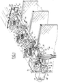
- the apparatus shown in fig. 1 consists of a hollow profile 1, which is preferably tubular and has a longitudinal slit 2 in the bottom wall, through which the depending members 3 of each slat 4 can move.
- the profile 1 is fixed to the ceiling or other fixed construction part in a manner not shown further but such that the continuous groove 2 lies on the underside of the profile.
- Carriers 5 are received in the profile, wherein each carrier is provided on either side with a travel wheel 6. This travel wheel is freely rotatable around a fixed pin 7 on the carrier 5.
- the carrier 5 with pin 7 is preferably formed as a single moulding of suitable material, for instance plastic.
- a gear transmission 8 consisting of a worm gear 9 and a pinion 10.
- the worm gear 9 has a central opening, through which is carried a control rod 11 extending parallel in the profile.
- the control rod 11 is non-round, this such that when the rod 11 is turned the worm gear 9 can rotate therewith.
- the worm gear 9 therein sets the pinion 10 in rotation.
- a spindle 12 of the depending member 3 is inserted into the hollow core of the pinion 10.
- Each carrier 5 is subsequently provided with a spacer 66 which is embodied as a strip of suitable material, and which according to the invention is mounted fixedly with one end in a recess 13 in the side of the carrier 5.
- the recess is further provided with a standing strip 14 at an interval from the bottom of the recess 13, this such that not only can the one end of the strip 66 be carried into the space between element 14 and the bottom of recess 13 but also the other end of the standing strip 66 of an adjacent carrier, see at 17 in fig. 1.
- the other end of the strip 66 is provided with a stop 18, which prevents the other end being pulled out between the recess 13 of the adjacent carrier.
- the profile 1 is provided on the inside with a rib 20 oriented parallel to the top and bottom wall, which forms with the bottom wall 21 and the side wall 22 a chamber 23 extending to the side of the travel path of the carriers 5.
- This chamber 23 serves to receive the strips 66 pushed on top of each other when the carriers are pulled against each other.
- the rib 20 also serves to support the travel wheels 7 of the carriers 5 since with the top wall 24 of the profile 1 this rib 20 forms a rail-like guiding, see also fig. 4.
- an arm 27 is also arranged in the top wall 24 in which the end 26 of an arm 27 can slide.
- This arm 27 serves to prevent the carriers 5 from tilting and going out of square in the profile 1 and thus to facilitate the sliding of the carriers 5 along the rod 11 and the sliding of the strip 66 in the recess 13. If necessary, an arm 27' with a similar function can likewise be arranged on the underside of the carrier 5, see fig. 3.
- the carriers 5 can slide in the profile 1 in the direction of the arrow P1 by means of a control member in the form of a pull cord 30.
- Shown at bottom left in fig. 1 are two parts of the pull cord 30 which is guided around a reversing wheel at the end (not shown) of profile 1.
- a part of the pull cord 30 is fixed to the last carrier in the row, which is likewise not shown.
- the last carrier is therefore moved reciprocally by the pull cords 30, which last carrier pulls the following carrier along with it by means of the strips 66 each time the maximum distance between the carriers is reached.
- the last carrier will push the preceding carriers onward until they lie against each other.
- the pull cord 30 can be trained through the profile 1 in a head end element 32 via guide wheels 31, wherein the cords move through an opening 33 of each carrier 5.
- the head end element 32 is also an end bearing for the rod 11, in which bearing the rod 11 is received for free rotation.
- the end of the rod 11 protruding outside the bearing is provided with a gear wheel 34 which is in engagement with a pinion 35 of a drive wheel 36.
- the drive wheel 36 is provided with a peripheral ring 37 with recesses for receiving a ball chain 38 which, when one of the parts of the chain 38 is pulled, causes the ring wheel 37 to turn in the direction of the arrow P2 whereby the gear wheel 34 is also set into rotation according to arrow P3 via the gear wheel 35.
- the gear wheel 34 carries the rod 11 with it and therewith all the worm gears 9 in each carrier 5.
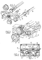
- the head end element 32 is embodied like the carriers as a single injection moulding in which the various components are mounted for free rotation.
- the guide wheel 31 for the cord 30 is for instance provided at either end with a stub 40 which is received in a recess 42 of a wall of the moulding 32.
- the cord guiding is ensured by a cap-like insert piece 41 with arcuate recess 42 which can be pushed into the injection moulded piece 32 according to arrow P4.
- a circular rear wall 43 of the insert piece 41 is provided with through-holes 44 for passage of the cord parts 30.
- Recessed into a bridge piece 45 of the injection moulding 32 is an opening 46 for receiving a shaft stub 47 of the ring wheel 37.
- the other end of the shaft stub 47 is received rotatably in a head end cover 48 which can be connected to the injection moulded piece 32 by means of screws 49 via a side wall 50 of the injection moulding 32 formed in alignment with the profile 1. In this way the entire mounting of the cord drive system and the rotation setting system of the slats 4 is achieved with only two screws 49 on either side of the head end cover 48.
- Fig. 5 shows an embodiment of the carrier 5 wherein a vertical standing spacer strip 66 is arranged on either side of the carrier.
- the spacer strips can be received in a like chamber 23 on the other side of the profile 1, see fig. 4, such that hardly any increase in the dimensions of the profile 1 is necessary.
- the spindle 12 which is carried through the pinion 10, carries as one piece on its underside a depending member 3 which has a pincer-shaped form.
- the two oppositely located parts of the pincer are somewhat flexible relative to one another because of the use of plastic, so that a slat strip 60 arranged on the slat and provided with a suspension bracket 61 can be placed through the slit between the pincer parts 3 in the direction of the arrow P6.
- the bracket 61 therein has a thickened upper portion 62, which prevents the slat being pulled out of the pincer-shaped depending member 3 unexpectedly. If the slat needs to be replaced, then the bracket 62 only needs to be pushed out of the pincer-shaped depending member 3 in the direction of the arrow P7.
- the central opening of the worm gear 9 is embodied with a longitudinal key 50 which fits into the longitudinal groove 51 of the rod 11. This makes possible sliding of the worm gear 9 and therefore sliding of the carriers 5 relative to the rod 11 but when the rod 11 is rotated the worm gear 9 can also be rotated.
- the worm gear 9 which has one screw thread 52 is rotated, the pinion 10 which is received in the carrier 5 for free rotation will be rotated.
- the spindle 12 By passing the spindle 12 through the central opening of the pinion 10 the top end of the spindle comes to lie beyond the top end of the pinion 10, which fits in the bearing-like opening of the carrier 5. In this way the pinion 10 is automatically bearing mounted in the carrier 5.
- the pinion 10 is embodied on the top side with inward pointing flanges 53 which rest resiliently against a slanting surface 54 of the spindle 12. This resilient action ensures a friction between the spindle 12 and the pinion 10, so that when the spindle 12 becomes jammed as a result of an obstruction on the slat 4 the rod 11 can still be rotated further since the pinion 10 can be rotated freely relative to the spindle 12.
- the spindle 12 is embodied in similar manner with a slanting surface 54 which co-acts with the friction flanges 53 of pinion 10.
- the spindle 12 is further provided with a protrusion 55 which falls into the slit between the flanges 53 of pinion 10, thus effecting a non-rotatable connection between spindle 12 and pinion 10.
- the rod 11 is provided here with three grooves 51' which co-act with the ridges 50' of a friction sleeve 56.
- This friction sleeve is embodied with an outward protruding resilient ridge 57 which co-acts with an axial toothing 58 on the inner wall of the central opening of the worm gear 9.
- a friction clutch is therefore also obtained here which enables a relative movement between the rotation of the rod 11 and of the spindle 12.
- the thickened head of the spindle 12 lies against the end edge of the flanges 53 in order to be able to lock the spindle 12 in the pinion 10 in axial direction. This is the second function of the flanges 53.
- the spindle can herein be removed from the pinion without having to slide the carriers out of the guiding.
- the profile 4 is embodied at the top surface 24 with outward protruding flange edges 60 which can serve for arranging additional profiles 61.
- These additional profiles 61 can be embodied hollow with forms of a continuous chamber 62 in which lines of a random nature can be accommodated.
- the profile 61 can be fixed to a ceiling strip 65 with a snap connection at 64. This greatly facilitates assembly. Other assembly systems for arranging the profile 1 on the ceiling can of course be applied.
Landscapes
- Engineering & Computer Science (AREA)
- Structural Engineering (AREA)
- Architecture (AREA)
- Civil Engineering (AREA)
- Blinds (AREA)
- Building Awnings And Sunshades (AREA)
- Tents Or Canopies (AREA)
- Transition And Organic Metals Composition Catalysts For Addition Polymerization (AREA)
- Vehicle Body Suspensions (AREA)
- Air Conditioning Control Device (AREA)
- Electric Clocks (AREA)
- Specific Sealing Or Ventilating Devices For Doors And Windows (AREA)
Claims (8)
- Vorrichtung zum Aufhängen lamellenartiger Markisen oder ähnlichem, mit:einer Schiene (10) mit einem rechteckigen Profil mit einer oberen Wand (24), zwei Seitenwänden (22) und einer Bodenwand (21), die mit einem Längsschlitz (2) versehen ist, wobei die Schiene (1) ein Mittel (20) aufweist, das einen Führungsweg für eine Zahl von Trägern (5) definiert, das Führungsmittel (20) in der Form einer nach innen gerichteten Rippe auf jeder Seitenwand (22) zwischen der Bodenwand (21) und der oberen Wand (24) so gebildet ist, daß eine Kammer (23) zwischen dem Führungswegmittel (20) der Bodenwand (21) und den Seitenwänden (22) gebildet ist;wobei die Zahl der Träger (5) je ein Zahnradgetriebe (8) aufweist, die Träger (5) bewegbar entlang der Schiene (1) durch ein Steuermittel (30) sind;einer drehbaren Steuerstange (11), die in und parallel zu der Schiene (1) angeordnet ist, wobei die Steuerstangen (1) sich durch ein Zahnradteil des Getriebes (8) eines jeden Trägers (5) erstreckt;einer vertikal drehbaren Spindel (12), die von jedem der Träger (5) gelagert ist und mit dem anderen Teil des Zahnradgetriebes (8) verbunden ist, wobei jede Spindel (12) ein herabweisendes Teil zum Aufnehmen der lamellenartigen Markisen oder ähnlichem aufweist; undeinem Abstandsstreifen (66), der mit jedem der Träger (5) verbunden ist und gleitend verschiebbar in einer Ausnehmung (13) des benachbarten Trägers geführt ist;dadurch gekennzeichnet,
daß jeder der Abstandsstreifen (66) an der Seite eines entsprechenden der Träger (5) derart befestigt ist, daß das Blatt des Streifens vertikal orientiert ist, und daß die Abstandsstreifen (66) in der Kammer (23) der Schiene (1) unterhalb der Rippe (20) aufgenommen sind. - Vorrichtung nach Anspruch 1, weiter mit einem Paar von Rädern (6) wobei die Räder (6) eines jeden Paares drehbar auf gegenüberliegenden Seiten eines jeden der Träger (5) angebracht sind.
- Vorrichtung nach Anspruch 2, dadurch gekennzeichnet, daß der Abstand zwischen den Rippen (20) und der oberen Wand (24) nur wenig den Durchmesser der Trägerräder (6) überschreitet und wobei der Abstand zwischen den Rippen (20) und der Bodenwand (21) nur wenig die vertikale Höhe der Abstandsstreifen (66) überschreitet.
- Vorrichtung nach Anspruch 1, dadurch gekennzeichnet, daß eine Rille in der oberen Wand (24) zum Aufnehmen eines Endes (26) eines Armes (27) angeordnet ist, der an dem Träger (5) angebracht ist.
- Gerät nach Anspruch 1, dadurch gekennzeichnet, daß die Abstandsstreifen (66) auf beiden Seiten der Träger (5) angeordnet sind.
- Vorrichtung nach Anspruch 1, dadurch gekennzeichnet, daß das Zahnradgetriebe ein Schneckenrad (9) und ein Ritzel (10), das damit zusammenwirkt, aufweist und wobei eine Reibungskupplung zwischen das Schneckenrad (9) und die Steuerstange (11) gesetzt ist.
- Vorrichtung nach Anspruch 1, dadurch gekennzeichnet, daß das Zahnradgetriebe ein Schneckenrad (9) und ein Ritzel (10), das damit zusammen wirkt, aufweist und wobei eine Reibungskupplung zwischen das Ritzel (10) und die Spindel (12) gesetzt ist.
- Vorrichtung nach Anspruch 1, dadurch gekennzeichnet, daß das Steuermittel (30) eine Zugschnur aufweist, die sich entlang der Steuerstange (11) durch Öffnungen (33) in den Trägern (5) erstreckt, und wobei ein Kopfendelement (32) auf mindestens einem Längsende der Schienen (1) vorgesehen ist, das Kopfendelement (32) ein Paar von nebeneinander angeordneten Öffnungen aufweist, eine der Öffnungen ein Lager für die Steuerstange (11) bildet, während die andere der Öffnungen einen Schnurführungseinsatz (41) zum Führen der Zugschnur (30) aufnimmt.
Applications Claiming Priority (3)
| Application Number | Priority Date | Filing Date | Title |
|---|---|---|---|
| NL8903061 | 1989-12-13 | ||
| NL8903061A NL8903061A (nl) | 1989-12-13 | 1989-12-13 | Inrichting voor het ophangen van lamelvormige zonwering of dergelijke. |
| PCT/NL1990/000181 WO1991009200A1 (en) | 1989-12-13 | 1990-12-13 | Apparatus for suspending lamellar sun-blinds or the like |
Publications (2)
| Publication Number | Publication Date |
|---|---|
| EP0457896A1 EP0457896A1 (de) | 1991-11-27 |
| EP0457896B1 true EP0457896B1 (de) | 1996-08-28 |
Family
ID=19855776
Family Applications (1)
| Application Number | Title | Priority Date | Filing Date |
|---|---|---|---|
| EP91901594A Expired - Lifetime EP0457896B1 (de) | 1989-12-13 | 1990-12-13 | Vorrichtung für hängende lamellenartige markisen oder ähnliches |
Country Status (13)
| Country | Link |
|---|---|
| EP (1) | EP0457896B1 (de) |
| JP (1) | JPH04505487A (de) |
| AT (1) | ATE141995T1 (de) |
| AU (1) | AU637667B2 (de) |
| CA (1) | CA2046327A1 (de) |
| DE (1) | DE69028293T2 (de) |
| DK (1) | DK0457896T3 (de) |
| ES (1) | ES2090305T3 (de) |
| HU (1) | HUT61071A (de) |
| NL (1) | NL8903061A (de) |
| NO (1) | NO913132L (de) |
| RU (1) | RU2070634C1 (de) |
| WO (1) | WO1991009200A1 (de) |
Families Citing this family (6)
| Publication number | Priority date | Publication date | Assignee | Title |
|---|---|---|---|---|
| GB9203891D0 (en) * | 1992-02-24 | 1992-04-08 | Hunter Douglas Ind Bv | Vertical blind system |
| GB2322152B (en) * | 1997-02-14 | 2000-09-20 | Louver Lite Ltd | Assembly for carrying a louvre in a vertical louvre blind |
| GB2335222B (en) * | 1998-03-09 | 2002-05-15 | Louver Lite Ltd | Louvre carrier for a louvre blind |
| GB0002134D0 (en) * | 2000-02-01 | 2000-03-22 | Harris Parts Limited | Vertical louvre blinds |
| JP2014001597A (ja) * | 2012-06-20 | 2014-01-09 | Tachikawa Blind Mfg Co Ltd | 縦型ブラインド |
| RU197832U1 (ru) * | 2020-03-02 | 2020-06-02 | Алексей Владимирович Демидов | Профиль направляющей для жалюзи |
Citations (1)
| Publication number | Priority date | Publication date | Assignee | Title |
|---|---|---|---|---|
| EP0242071A1 (de) * | 1986-04-18 | 1987-10-21 | Hunter Douglas Industries B.V. | Lamellenstore mit vertikalen Lamellen und Laufwagen dafür |
Family Cites Families (6)
| Publication number | Priority date | Publication date | Assignee | Title |
|---|---|---|---|---|
| US2794502A (en) * | 1956-02-14 | 1957-06-04 | Andrew J Toti | Vertical slat blind |
| FI70978C (fi) * | 1981-12-07 | 1986-10-27 | Bratschi Silent Gliss | Lamellgardin |
| IT8321445U1 (it) * | 1983-04-06 | 1984-10-06 | Vitari Giuseppe | Dispositivo ad ingranaggi, per l'orientamento ed il trascinamento delle strisce, nelle tende verticali a lamelle |
| US4559670A (en) * | 1983-11-10 | 1985-12-24 | Wyatt James L | Adjustable carrier assembly for a vertical louver with spacer link |
| NL8800049A (nl) * | 1988-01-08 | 1989-08-01 | Allpac Holding B V Handelend O | Ophangsysteem voor vertikale jalouzieen. |
| US4848435A (en) * | 1988-11-03 | 1989-07-18 | Oscar Helver | Vertical blind assembly |
-
1989
- 1989-12-13 HU HU912667A patent/HUT61071A/hu unknown
- 1989-12-13 NL NL8903061A patent/NL8903061A/nl not_active Application Discontinuation
-
1990
- 1990-12-13 DK DK91901594.1T patent/DK0457896T3/da active
- 1990-12-13 AU AU69706/91A patent/AU637667B2/en not_active Ceased
- 1990-12-13 CA CA002046327A patent/CA2046327A1/en not_active Abandoned
- 1990-12-13 RU SU905001500A patent/RU2070634C1/ru active
- 1990-12-13 DE DE69028293T patent/DE69028293T2/de not_active Expired - Fee Related
- 1990-12-13 JP JP3501887A patent/JPH04505487A/ja active Pending
- 1990-12-13 EP EP91901594A patent/EP0457896B1/de not_active Expired - Lifetime
- 1990-12-13 ES ES91901594T patent/ES2090305T3/es not_active Expired - Lifetime
- 1990-12-13 AT AT91901594T patent/ATE141995T1/de not_active IP Right Cessation
- 1990-12-13 WO PCT/NL1990/000181 patent/WO1991009200A1/en not_active Ceased
-
1991
- 1991-08-12 NO NO91913132A patent/NO913132L/no unknown
Patent Citations (1)
| Publication number | Priority date | Publication date | Assignee | Title |
|---|---|---|---|---|
| EP0242071A1 (de) * | 1986-04-18 | 1987-10-21 | Hunter Douglas Industries B.V. | Lamellenstore mit vertikalen Lamellen und Laufwagen dafür |
Also Published As
| Publication number | Publication date |
|---|---|
| NO913132D0 (no) | 1991-08-12 |
| DE69028293D1 (de) | 1996-10-02 |
| ATE141995T1 (de) | 1996-09-15 |
| DK0457896T3 (da) | 1996-10-07 |
| WO1991009200A1 (en) | 1991-06-27 |
| AU637667B2 (en) | 1993-06-03 |
| AU6970691A (en) | 1991-07-18 |
| ES2090305T3 (es) | 1996-10-16 |
| HU912667D0 (en) | 1992-01-28 |
| CA2046327A1 (en) | 1991-06-14 |
| EP0457896A1 (de) | 1991-11-27 |
| HUT61071A (en) | 1992-11-30 |
| RU2070634C1 (ru) | 1996-12-20 |
| NL8903061A (nl) | 1991-07-01 |
| JPH04505487A (ja) | 1992-09-24 |
| DE69028293T2 (de) | 1997-01-16 |
| NO913132L (no) | 1991-10-11 |
Similar Documents
| Publication | Publication Date | Title |
|---|---|---|
| US5289863A (en) | Apparatus for suspending lamellar sun-blinds or the like | |
| US7464742B2 (en) | Raising and lowering mechanism for blinds | |
| US4122884A (en) | Vertical venetian blind construction | |
| FI70978C (fi) | Lamellgardin | |
| CA2213807C (en) | Combined tilt and raise control for window coverings | |
| US5127192A (en) | Pivot shoe for removable sash | |
| US4557310A (en) | Movable sun shade system | |
| US5119868A (en) | Venetian blind with a three-position tilt adjustment | |
| US4425956A (en) | Vertical blind mechanism | |
| EP0960252B1 (de) | Tragebandwickelvorrichtung für fensterabdeckung | |
| EP0457896B1 (de) | Vorrichtung für hängende lamellenartige markisen oder ähnliches | |
| US5819831A (en) | Roller blind drive, more particularly for shade producing means | |
| CA1302228C (en) | Vertical blinds | |
| US4559670A (en) | Adjustable carrier assembly for a vertical louver with spacer link | |
| US3982355A (en) | Adjustable blind structure | |
| US4913210A (en) | Cord lock for window shades | |
| US4844139A (en) | Vertical louver blind having clutched operating mechanism | |
| NL9100871A (nl) | Ophangeenheid voor een zonwering met verticale lamellen. | |
| EP3581753B1 (de) | Schiebeabschirmvorrichtung | |
| US5887636A (en) | Venetian blind | |
| US5238042A (en) | Window blind system | |
| US4688618A (en) | Carrier assembly for vertical blinds | |
| EP0562711A2 (de) | Vertikaler Lamellenvorhang | |
| US5699846A (en) | Wand-controlled split-draw vertical blind headrail | |
| US6105656A (en) | Carrier assembly for vertical blinds |
Legal Events
| Date | Code | Title | Description |
|---|---|---|---|
| PUAI | Public reference made under article 153(3) epc to a published international application that has entered the european phase |
Free format text: ORIGINAL CODE: 0009012 |
|
| AK | Designated contracting states |
Kind code of ref document: A1 Designated state(s): AT BE CH DE DK ES FR GB GR IT LI LU NL SE |
|
| 17P | Request for examination filed |
Effective date: 19911213 |
|
| 17Q | First examination report despatched |
Effective date: 19930225 |
|
| GRAH | Despatch of communication of intention to grant a patent |
Free format text: ORIGINAL CODE: EPIDOS IGRA |
|
| GRAH | Despatch of communication of intention to grant a patent |
Free format text: ORIGINAL CODE: EPIDOS IGRA |
|
| ITF | It: translation for a ep patent filed | ||
| GRAA | (expected) grant |
Free format text: ORIGINAL CODE: 0009210 |
|
| AK | Designated contracting states |
Kind code of ref document: B1 Designated state(s): AT BE CH DE DK ES FR GB GR IT LI LU NL SE |
|
| PG25 | Lapsed in a contracting state [announced via postgrant information from national office to epo] |
Ref country code: GR Free format text: LAPSE BECAUSE OF FAILURE TO SUBMIT A TRANSLATION OF THE DESCRIPTION OR TO PAY THE FEE WITHIN THE PRESCRIBED TIME-LIMIT Effective date: 19960828 Ref country code: BE Effective date: 19960828 |
|
| REF | Corresponds to: |
Ref document number: 141995 Country of ref document: AT Date of ref document: 19960915 Kind code of ref document: T |
|
| REG | Reference to a national code |
Ref country code: CH Ref legal event code: NV Representative=s name: ARNOLD & SIEDSMA AG |
|
| REF | Corresponds to: |
Ref document number: 69028293 Country of ref document: DE Date of ref document: 19961002 |
|
| REG | Reference to a national code |
Ref country code: DK Ref legal event code: T3 |
|
| ET | Fr: translation filed | ||
| REG | Reference to a national code |
Ref country code: ES Ref legal event code: FG2A Ref document number: 2090305 Country of ref document: ES Kind code of ref document: T3 |
|
| REG | Reference to a national code |
Ref country code: ES Ref legal event code: FG2A Ref document number: 2090305 Country of ref document: ES Kind code of ref document: T3 |
|
| PG25 | Lapsed in a contracting state [announced via postgrant information from national office to epo] |
Ref country code: SE Effective date: 19961128 |
|
| PG25 | Lapsed in a contracting state [announced via postgrant information from national office to epo] |
Ref country code: GB Effective date: 19961213 Ref country code: DK Effective date: 19961213 Ref country code: AT Effective date: 19961213 |
|
| REG | Reference to a national code |
Ref country code: DK Ref legal event code: EBP |
|
| PG25 | Lapsed in a contracting state [announced via postgrant information from national office to epo] |
Ref country code: LU Free format text: LAPSE BECAUSE OF NON-PAYMENT OF DUE FEES Effective date: 19961231 Ref country code: LI Effective date: 19961231 Ref country code: CH Effective date: 19961231 |
|
| NLV1 | Nl: lapsed or annulled due to failure to fulfill the requirements of art. 29p and 29m of the patents act | ||
| PLBI | Opposition filed |
Free format text: ORIGINAL CODE: 0009260 |
|
| PLBQ | Unpublished change to opponent data |
Free format text: ORIGINAL CODE: EPIDOS OPPO |
|
| PLBF | Reply of patent proprietor to notice(s) of opposition |
Free format text: ORIGINAL CODE: EPIDOS OBSO |
|
| 26 | Opposition filed |
Opponent name: BENTHIN AKTIENGESELLSCHAFT Effective date: 19970527 |
|
| GBPC | Gb: european patent ceased through non-payment of renewal fee |
Effective date: 19961213 |
|
| REG | Reference to a national code |
Ref country code: CH Ref legal event code: PL |
|
| NLXE | Nl: other communications concerning ep-patents (part 3 heading xe) |
Free format text: A REQUEST FOR RESTORATION TO THE PRIOR STATE HAS BEEN FILED ON 970702 |
|
| PLBF | Reply of patent proprietor to notice(s) of opposition |
Free format text: ORIGINAL CODE: EPIDOS OBSO |
|
| PG25 | Lapsed in a contracting state [announced via postgrant information from national office to epo] |
Ref country code: ES Free format text: LAPSE BECAUSE OF NON-PAYMENT OF DUE FEES Effective date: 19971214 |
|
| NLXE | Nl: other communications concerning ep-patents (part 3 heading xe) |
Free format text: THE REQUEST FOR RESTORATION TO THE PRIOR STATE AS PROVIDED FOR IN ART. 23 OF THE PATENTS ACT 1995 (SEE PUBLICATION IN HEADING XE OF THE PATENT BULLETIN OF 01.09.97/09) HAS BEEN GRANTED; THE RESTORATION OF THE PATENT HAS BEEN ENTERED IN THE PATENT REGISTER. |
|
| PLBF | Reply of patent proprietor to notice(s) of opposition |
Free format text: ORIGINAL CODE: EPIDOS OBSO |
|
| NLV4 | Nl: lapsed or anulled due to non-payment of the annual fee |
Effective date: 19970701 |
|
| PLBO | Opposition rejected |
Free format text: ORIGINAL CODE: EPIDOS REJO |
|
| APAC | Appeal dossier modified |
Free format text: ORIGINAL CODE: EPIDOS NOAPO |
|
| APAE | Appeal reference modified |
Free format text: ORIGINAL CODE: EPIDOS REFNO |
|
| APAC | Appeal dossier modified |
Free format text: ORIGINAL CODE: EPIDOS NOAPO |
|
| NLS | Nl: assignments of ep-patents |
Owner name: HUNTER DOUGLAS INDUSTRIES B.V. |
|
| PGFP | Annual fee paid to national office [announced via postgrant information from national office to epo] |
Ref country code: NL Payment date: 19981229 Year of fee payment: 9 |
|
| PG25 | Lapsed in a contracting state [announced via postgrant information from national office to epo] |
Ref country code: NL Free format text: LAPSE BECAUSE OF NON-PAYMENT OF DUE FEES Effective date: 20000701 |
|
| APAC | Appeal dossier modified |
Free format text: ORIGINAL CODE: EPIDOS NOAPO |
|
| PLBN | Opposition rejected |
Free format text: ORIGINAL CODE: 0009273 |
|
| STAA | Information on the status of an ep patent application or granted ep patent |
Free format text: STATUS: OPPOSITION REJECTED |
|
| NLV4 | Nl: lapsed or anulled due to non-payment of the annual fee |
Effective date: 20000701 |
|
| 27O | Opposition rejected |
Effective date: 20000404 |
|
| REG | Reference to a national code |
Ref country code: ES Ref legal event code: FD2A Effective date: 19980113 |
|
| APAH | Appeal reference modified |
Free format text: ORIGINAL CODE: EPIDOSCREFNO |
|
| PG25 | Lapsed in a contracting state [announced via postgrant information from national office to epo] |
Ref country code: IT Free format text: LAPSE BECAUSE OF NON-PAYMENT OF DUE FEES Effective date: 20051213 |
|
| PGFP | Annual fee paid to national office [announced via postgrant information from national office to epo] |
Ref country code: DE Payment date: 20061207 Year of fee payment: 17 |
|
| PGFP | Annual fee paid to national office [announced via postgrant information from national office to epo] |
Ref country code: FR Payment date: 20061208 Year of fee payment: 17 |
|
| PG25 | Lapsed in a contracting state [announced via postgrant information from national office to epo] |
Ref country code: DE Free format text: LAPSE BECAUSE OF NON-PAYMENT OF DUE FEES Effective date: 20080701 |
|
| REG | Reference to a national code |
Ref country code: FR Ref legal event code: ST Effective date: 20081020 |
|
| PG25 | Lapsed in a contracting state [announced via postgrant information from national office to epo] |
Ref country code: FR Free format text: LAPSE BECAUSE OF NON-PAYMENT OF DUE FEES Effective date: 20071231 |