EP0457700B1 - Dispositif d'accouplement à boisseaux tournants pour tuyauteries - Google Patents
Dispositif d'accouplement à boisseaux tournants pour tuyauteries Download PDFInfo
- Publication number
- EP0457700B1 EP0457700B1 EP19910420162 EP91420162A EP0457700B1 EP 0457700 B1 EP0457700 B1 EP 0457700B1 EP 19910420162 EP19910420162 EP 19910420162 EP 91420162 A EP91420162 A EP 91420162A EP 0457700 B1 EP0457700 B1 EP 0457700B1
- Authority
- EP
- European Patent Office
- Prior art keywords
- elements
- cocks
- plug
- coupling
- coupling device
- Prior art date
- Legal status (The legal status is an assumption and is not a legal conclusion. Google has not performed a legal analysis and makes no representation as to the accuracy of the status listed.)
- Expired - Lifetime
Links
Images


Classifications
-
- F—MECHANICAL ENGINEERING; LIGHTING; HEATING; WEAPONS; BLASTING
- F16—ENGINEERING ELEMENTS AND UNITS; GENERAL MEASURES FOR PRODUCING AND MAINTAINING EFFECTIVE FUNCTIONING OF MACHINES OR INSTALLATIONS; THERMAL INSULATION IN GENERAL
- F16L—PIPES; JOINTS OR FITTINGS FOR PIPES; SUPPORTS FOR PIPES, CABLES OR PROTECTIVE TUBING; MEANS FOR THERMAL INSULATION IN GENERAL
- F16L29/00—Joints with fluid cut-off means
- F16L29/04—Joints with fluid cut-off means with a cut-off device in each of the two pipe ends, the cut-off devices being automatically opened when the coupling is applied
-
- F—MECHANICAL ENGINEERING; LIGHTING; HEATING; WEAPONS; BLASTING
- F16—ENGINEERING ELEMENTS AND UNITS; GENERAL MEASURES FOR PRODUCING AND MAINTAINING EFFECTIVE FUNCTIONING OF MACHINES OR INSTALLATIONS; THERMAL INSULATION IN GENERAL
- F16L—PIPES; JOINTS OR FITTINGS FOR PIPES; SUPPORTS FOR PIPES, CABLES OR PROTECTIVE TUBING; MEANS FOR THERMAL INSULATION IN GENERAL
- F16L37/00—Couplings of the quick-acting type
- F16L37/28—Couplings of the quick-acting type with fluid cut-off means
- F16L37/30—Couplings of the quick-acting type with fluid cut-off means with fluid cut-off means in each of two pipe-end fittings
- F16L37/373—Couplings of the quick-acting type with fluid cut-off means with fluid cut-off means in each of two pipe-end fittings with two taps or cocks
-
- Y—GENERAL TAGGING OF NEW TECHNOLOGICAL DEVELOPMENTS; GENERAL TAGGING OF CROSS-SECTIONAL TECHNOLOGIES SPANNING OVER SEVERAL SECTIONS OF THE IPC; TECHNICAL SUBJECTS COVERED BY FORMER USPC CROSS-REFERENCE ART COLLECTIONS [XRACs] AND DIGESTS
- Y10—TECHNICAL SUBJECTS COVERED BY FORMER USPC
- Y10T—TECHNICAL SUBJECTS COVERED BY FORMER US CLASSIFICATION
- Y10T137/00—Fluid handling
- Y10T137/8593—Systems
- Y10T137/87096—Valves with separate, correlated, actuators
- Y10T137/87105—Correlated across separable flow path joint
-
- Y—GENERAL TAGGING OF NEW TECHNOLOGICAL DEVELOPMENTS; GENERAL TAGGING OF CROSS-SECTIONAL TECHNOLOGIES SPANNING OVER SEVERAL SECTIONS OF THE IPC; TECHNICAL SUBJECTS COVERED BY FORMER USPC CROSS-REFERENCE ART COLLECTIONS [XRACs] AND DIGESTS
- Y10—TECHNICAL SUBJECTS COVERED BY FORMER USPC
- Y10T—TECHNICAL SUBJECTS COVERED BY FORMER US CLASSIFICATION
- Y10T137/00—Fluid handling
- Y10T137/8593—Systems
- Y10T137/87917—Flow path with serial valves and/or closures
- Y10T137/87925—Separable flow path section, valve or closure in each
- Y10T137/87941—Each valve and/or closure operated by coupling motion
-
- Y—GENERAL TAGGING OF NEW TECHNOLOGICAL DEVELOPMENTS; GENERAL TAGGING OF CROSS-SECTIONAL TECHNOLOGIES SPANNING OVER SEVERAL SECTIONS OF THE IPC; TECHNICAL SUBJECTS COVERED BY FORMER USPC CROSS-REFERENCE ART COLLECTIONS [XRACs] AND DIGESTS
- Y10—TECHNICAL SUBJECTS COVERED BY FORMER USPC
- Y10T—TECHNICAL SUBJECTS COVERED BY FORMER US CLASSIFICATION
- Y10T137/00—Fluid handling
- Y10T137/8593—Systems
- Y10T137/87917—Flow path with serial valves and/or closures
- Y10T137/87925—Separable flow path section, valve or closure in each
- Y10T137/87973—Coupling interlocked with valve, or closure or actuator
Definitions
- the present invention relates to fittings for pipes and it relates more particularly to coupling devices in which each of the two elements fixed to the ends of the pipes to be joined together is equipped with a valve constituted by a substantially spherical plug suitable for turning on itself. even to pass from the open position to the closed position and vice versa, this movement taking place automatically by means of axial displacement of one of said elements relative to the other.
- the latter relates to the coupling device which is defined in claim 1.
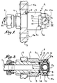
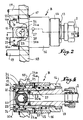
- Fig. 1 and 2 show the two elements of a coupling device established according to the invention.
- Fig. 3 and 4 are axial sections along the planes respectively indicated in III-III in fig. 1 and IV-IV in fig. 2.
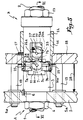
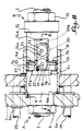
- Fig. 5 shows the two elements fitted one inside the other in the locked position.
- Fig. 6 is the axial section along the plane indicated in VI-VI in FIG. 5.
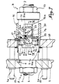
- Fig. 7 and 8 reproduce fig. 5 in two successive phases of the valve opening process.
- Fig. 9 and 10 are detailed axial sections respectively on the plan indicated in IX-IX (fig. 7) and X-X (fig. 8).
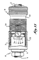
- Fig. 11 illustrates a variant implementation of the invention.
- the coupling device comprises two elements A (fig. 1) and B (fig. 2) whose body is arranged at the rear part to be fixed to the end of the two flexible pipes 1 and 2 to mate.
- the body of element A (fig. 1 and 3) is formed by two tubular parts 3 and 4 provided threaded to be assembled to each other by screwing by tightening between them a support plate 5 equipped with guide rings 5 a .
- the part 3 comprises an index finger 6 engaged in a corresponding cavity of the plate 5 in order to ensure the angular location of the body 3-4 relative to said plate.
- the body 3-4 contains a rotating plug 7 mounted between two seats 8 associated with a compensation joint 9.
- this plug 7 has an imprint in which is housed the screwdriver-shaped end of a small transverse shaft 10 mounted in leaktight manner in a corresponding hole in the end of the part 3.
- Each shaft 10 is provided with a control disc 11 cut from a notch 11 a .
- the plug 7 is crossed by a through hole 7 a , while its outer wall has a depression 7 b in the form of a semi-spherical cup whose radius is equal to the outside radius of the plug.
- the plug 7 is housed in a part or nose 3 a with a smaller diameter of the part 3 of the body 3-4, which nose is hollowed out by an annular groove 3 b .
- the discs 11 are placed at the level of two flats 3 c diametrically opposite one another on the nose 3 a , so that they do not determine any projection on the latter.
- the body of element B (fig. 2 and 4) has a more complex structure. Indeed, if there are indeed two tubular parts 12 and 13 assembled by screwing, the part 12 is surrounded by a movable ring 14 which a spring 15 tends to push backwards until it comes into abutment against a shoulder annular part 13.
- the ring 14 is itself disposed inside a socket 16 fixed, with the interposition of a locating index 17 similar to that 6 of the element A, to a support plate 18 provided with two parallel rods 19 able to slide inside guides 5a of the plate 5.
- the body 13-14 of the element B contains a rotary plug 20 pierced at 20 a like the plug 7 and mounted, like the latter, between two seats 21 associated with a compensation joint 22. It is also provided with two shafts 23 equipped with control discs 24 cut from a notch 24 a . These two discs 24 are arranged inside notched parts 14 a of the ring 14, which protrudes in front of the sleeve 16 and comprises clean perforations to form housings for balls 25, retained between the sleeve 16 and the outer wall of the tubular part 12.
- this part 12 is equipped with an O-ring 26. Furthermore, behind the plate 18, the sleeve 16 carries two fingers 27, diametrically opposite one another and which project radially inside the notched parts of the ring 14.
- the two support plates 5 and 18 are associated with a pneumatic, hydraulic or electric actuator, the two members of which (body and piston) are respectively fixed to said plates in order to bring them closer together or to spread them apart.
- the plate 5 is fixed, so that it is the plate 18 which is moved transversely to its axis by the above-mentioned jack, schematically represented in FIG. 5 by arrow 28.
- the device being assumed to be in the uncoupled position of the two elements A and B, it is understood that when the jack 28 begins its approach stroke, the ring 14 engages on the nose 3 a of the body 3-4 of the element A while the spool 20 is nested partially in the cavity 7b of the plug 7. the balls 25, which were initially disposed at the outlet thinned 16a of the sleeve 16 are pushed forward by the shoulder formed in this opening by driving the ring 14 until they are at the level of the groove 3b of the nose 3 is cited in which they are applied. Consequently, the two elements A and B of the device are locked axially to one another, in the manner illustrated in FIG. 5 and 6, it being observed that the two plugs 7 and 20 are always in the closed position.
- the fluid which flows through the two pipes 1 and 2 can then pass through the coupling device, without pressure drop and without coming into contact with a part of said device other than the wall of the axial bores of bodies 3-4 and 12-13. , the wall of the seats 8 and 21 and the wall of the bores 7 a and 20 a , all these walls having no contact with the outside environment and being, moreover, capable of being cleaned by means of a simple passage of fluid through the inside the device.
- the uncoupling can be obtained by actuating the actuator 28 upon expansion in order to separate the two plates 5 and 18.
- the fingers 27 will successively control the closure of the plug 7, then the plug 20; finally, the sleeve 16 returns to its initial position with its thinned outlet 16 a opposite the balls 25 which unlock the two elements A and B.
- the invention is capable of being advantageously implemented for the production of manually actuated coupling devices.
- the element A it suffices for this purpose to have the element A have a threaded operating ring 29 rotating on the periphery of the part 3 of the body 3-4, which ring 29 is capable of cooperating with a thread 30 provided on the periphery of the sleeve 16 by ensuring the reciprocal displacement of the two elements, in one direction or the other depending on the direction of the angular displacement imparted to said ring 29.
Description
- La présente invention a trait aux raccords pour tuyauteries et elle vise plus particulièrement les dispositifs d'accouplement dans lesquels chacun des deux éléments fixés aux extrémités des tuyauteries à réunir est équipé d'un clapet constitué par un boisseau substantiellement sphérique propre à tourner sur lui-même pour passer de la position d'ouverture à la position de fermeture et vice versa, ce mouvement s'effectuant de manière automatique moyennant déplacement axial de l'un desdits éléments par rapport à l'autre.
- La construction d'un tel dispositif reste relativement simple lorsque les deux boisseaux sont disposés à un certain écartement l'un de l'autre et peuvent de ce fait être commandés simultanément en rotation. Il n'en va pas de même par contre lorsqu'on désire éviter tout risque de mise en contact du liquide véhiculé avec l'ambiance extérieure par suite des risques de pollution qui seraient autrement engendrés ; en pareil cas, il est nécessaire qu'à la position accouplée des éléments, la protubérance semi-sphérique du boisseau de l'un de ceux-ci vienne se loger dans une dépression conjuguée ménagée dans la paroi de l'autre, et l'on comprend que l'interpénétration des deux parties à profil semi-sphérique s'oppose normalement à tout mouvement de rotation simultané des deux boisseaux ainsi emboîtés.
- Pour résoudre le problème ainsi posé, on prévoit généralement que la rotation des boisseaux au cours du mouvement longitudinal d'accouplement soit précédée par un déplacement axial ou recul de l'un au moins des deux à l'intérieur du corps qui le renferme. On comprend que si ce recul préalable permet bien ensuite la rotation simultanée des deux boisseaux du dispositif, il provoque le contact du liquide avec certaines des pièces de celui-ci, en impliquant de la sorte des opérations de nettoyage relativement compliquées si l'on entend éviter tout risque de pollution interne. Il convient en outre d'observer que les structures proposées sont complexes et renchérissent le coût de l'ensemble.
- Le document US-A-3 159 180 (COURTOT) illustre une solution qui a été proposée pour surmonter cet inconvénient, en évitant tout recul préalable de l'un des boisseaux. Il s'agit d'un raccord rapide du type dans lequel l'assemblage des deux éléments du dispositif est assuré par la rotation d'une pièce tournante de l'un par rapport à une pièce conjuguée de l'autre. Chaque boisseau est angulairement solidaire d'un disque qui est échancré radialement de façon à ce que lors de l'assemblage des deux éléments par rotation, un doigt prévu radialement sur l'élément opposé vienne entraîner angulairement ledit disque et son boisseau. Bien entendu les choses sont agencées de manière telle que les deux boisseaux tournent l'un après l'autre et que les deux éléments du raccord ne puissent être dissociés avant que lesdits boisseaux aient été amenés en position de fermeture.
- Cet agencement connu, satisfaisant pour les raccords rapides à assemblage par rotation, ne peut évidemment convenir pour les dispositifs d'accouplement dans lesquels l'assemblage des deux éléments implique le déplacement axial de l'un de ceux-ci par rapport à l'autre, et c'est à cette lacune qu'entend remédier la présente invention.
- Cette dernière a pour objet le dispositif d'accouplement qui est défini à la revendication 1.
- Le dessin annexé, donné à titre d'exemple, permettra de mieux comprendre l'invention, les caractéristiques qu'elle présente et les avantages qu'elle est susceptible de procurer :
- Fig. 1 et 2 montrent les deux éléments d'un dispositif d'accouplement établi suivant l'invention.
- Fig. 3 et 4 sont des coupes axiales suivant les plans respectivement indiqués en III-III sur fig. 1 et IV-IV sur fig. 2.
- Fig. 5 représente les deux éléments emmanchés l'un dans l'autre à la position verrouillée.
- Fig. 6 est la coupe axiale suivant le plan indiqué en VI-VI sur fig. 5.
- Fig. 7 et 8 reproduisent fig. 5 à deux phases successives du processus d'ouverture des boisseaux.
- Fig. 9 et 10 sont des coupes axiales de détail respectivement suivant les plan indiqués en IX-IX (fig. 7) et X-X (fig. 8).
- Fig. 11 illustre une variante de mise en oeuvre de l'invention.
- A la façon usuelle, le dispositif d'accouplement comprend deux éléments A (fig. 1) et B (fig. 2) dont le corps est agencé à la partie arrière pour être fixé à l'extrémité des deux tuyauteries flexibles 1 et 2 à accoupler.
- Le corps de l'élément A (fig. 1 et 3) est formé par deux pièces tubulaires 3 et 4 prévues filetées pour s'assembler l'une à l'autre par vissage en serrant entre elles une plaque-support 5 équipée de bagues de guidage 5a. On notera que la pièce 3 comporte un index 6 engagé dans une cavité correspondante de la plaque 5 en vue d'assurer le répérage angulaire du corps 3-4 par rapport à ladite plaque.
- A l'opposé de la tuyauterie 1, le corps 3-4 renferme un boisseau tournant 7 monté entre deux sièges 8 associés à un joint de compensation 9. En deux points diamétralement opposés, ce boisseau 7 comporte une empreinte dans laquelle est logée l'extrémité en forme de tournevis d'un petit arbre transversal 10 monté de manière étanche dans un perçage correspondant de l'extrémité de la pièce 3. Chaque arbre 10 est doté d'un disque de commande 11 découpé d'une entaille 11a. Bien évidemment, le boisseau 7 est traversé par un perçage débouchant 7a, tandis que sa paroi extérieure présente une dépression 7b en forme de cuvette semi-sphérique dont le rayon est égal au rayon extérieur du boisseau.
- Il convient d'observer que le boisseau 7 est logé dans une partie ou nez 3a à plus petit diamètre de la pièce 3 du corps 3-4, lequel nez est creusé d'une gorge annulaire 3b. Les disques 11 se trouvent placés au niveau de deux méplats 3c diamétralement opposés l'un à l'autre sur le nez 3a, de sorte qu'ils ne déterminent aucune saillie sur ce dernier.
- Le corps de l'élément B (fig. 2 et 4) présente une structure plus complexe. En effet, si l'on retrouve bien deux pièces tubulaires 12 et 13 assemblées par vissage, la pièce 12 est entourée par une bague mobile 14 qu'un ressort 15 tend à repousser vers l'arrière jusqu'à venir en butée contre un épaulement annulaire de la pièce 13. La bague 14 est elle-même disposée à l'intérieur d'une douille 16 fixée, avec interposition d'un index de repérage 17 analogue à celui 6 de l'élément A, à une plaque-support 18 pourvue de deux tiges parallèles 19 aptes à coulisser à l'intérieur des guides 5a de la plaque 5.
- Le corps 13-14 de l'élément B renferme un boisseau tournant 20 percé en 20a comme le boisseau 7 et monté, comme ce dernier, entre deux sièges 21 associés à un joint de compensation 22. Il est également pourvu de deux arbres 23 équipés de disques de commande 24 découpés d'une entaille 24a. Ces deux disques 24 se trouvent disposés à l'intérieur de parties entaillées 14a de la bague 14, laquelle dépasse en avant de la douille 16 et comporte des perforations propres à former logements pour des billes 25, retenues entre la douille 16 et la paroi extérieure de la pièce tubulaire 12.
- Immédiatement en avant du boisseau 20, cette pièce 12 est équipée d'un joint torique 26. Par ailleurs, en arrière de la plaque 18, la douille 16 porte deux doigts 27, diamétralement opposés l'un à l'autre et qui font saillie radialement à l'intérieur des parties entaillées de la bague 14.
- Avant d'exposer le fonctionnement du dispositif d'accouplement ci-dessus décrit, on indiquera qu'aux deux plaques-supports 5 et 18 est associé un vérin à actionnement pneumatique, hydraulique ou électrique, dont les deux organes (corps et piston) sont respectivement fixés aux-dites plaques en vue d'opérer leur rapprochement ou leur écartement mutuel. Afin de simplifier les explications qui vont suivre, on supposera que la plaque 5 est fixe, de sorte que c'est la plaque 18 qui est déplacée transversalement à son axe par le vérin précité, schématiquement représenté en fig. 5 par la flèche 28.
- Le dispositif étant supposé à la position désaccouplée des deux éléments A et B, on comprend que lorsque le vérin 28 entame sa course de rapprochement, la bague 14 vient s'engager sur le nez 3a du corps 3-4 de l'élément A, tandis que le boisseau 20 vient s'emboîter partiellement dans l'empreinte 7b du boisseau 7. Les billes 25, qui étaient initialement disposées au niveau du débouché aminci 16a de la douille 16, sont repoussées vers l'avant par l'épaulement formé dans ce débouché en entraînant la bague 14, jusqu'à ce qu'elles se trouvent au niveau de la gorge 3b du nez 3a précité dans laquelle elles sont appliquées. Dès lors, les deux éléments A et B du dispositif sont verrouillés axialement l'un à l'autre, à la manière illustrée en fig. 5 et 6, étant observé que les deux boisseaux 7 et 20 sont toujours à la position fermée.
- La poursuite du déplacement de la douille 16 sous l'action du vérin 28 va amener les doigts 27 à s'engager dans les entailles 24a des disques 24, puis à entraîner en rotation ces derniers. Par suite de la présence de la dépression 7b, le boisseau 20 peut tourner sur lui-même suivant un angle de 90°, en affectant finalement l'orientation d'ouverture illustrée en fig. 7 et 9. Poursuivant leur déplacement, les doigts 27 quittent les entailles 24a et s'introduisent dans les entailles 11a, de sorte qu'ils vont de la même manière assurer la commande des disques 11 associés au boisseau 7 ; la protubérance sphérique de ce boisseau 7 se trouve engagée dans le débouché du perçage 20a, de sorte que ledit boisseau 7 est libre de pivoter à son tour de 90° pour affecter la position ouverte suivant fig. 8 et 10.
- Le fluide qui parcourt les deux tuyauteries 1 et 2 peut alors traverser le dispositif d'accouplement, sans perte de charge et sans venir au contact d'une pièce dudit dispositif autre que la paroi des alésages axiaux des corps 3-4 et 12-13, la paroi des sièges 8 et 21 et la paroi des perçages 7a et 20a, toutes ces parois n'ayant aucun contact avec l'ambiance extérieure et étant au surplus susceptibles d'être nettoyées moyennant un simple passage de fluide à l'intérieur du dispositif.
- Il va de soi que le désaccouplement peut être obtenu en actionnant le vérin 28 à l'expansion afin d'écarter les deux plaques 5 et 18. Les doigts 27 vont successivement commander à la fermeture le boisseau 7, puis le boisseau 20 ; finalement, la douille 16 revient à sa position initiale avec son débouché aminci 16a en vis-à-vis des billes 25 qui déverrouillent les deux éléments A et B.
- On comprend sans peine que l'invention est susceptible d'être avantageusement mise en oeuvre pour la réalisation de dispositifs d'accouplement à actionnement manuel. Comme illustré en fig. 11, il suffit à cet effet de faire comporter à l'élément A une bague de manoeuvre filetée 29 tournant sur la périphérie de la pièce 3 du corps 3-4, laquelle bague 29 est propre à venir coopérer avec un filetage 30 prévu sur la périphérie de la douille 16 en assurant le déplacement réciproque des deux éléments, dans une direction ou dans l'autre suivant le sens du déplacement angulaire imparti à ladite bague 29.
Claims (2)
- Dispositif d'accouplement pour tuyauteries comprenant en combinaison :- deux éléments emmanchables (A et B) qui sont équipés de moyens (14-25) propres à assurer leur verrouillage et leur déverrouillage lors du mouvement axial impliqué par leur accouplement et leur désaccouplement ;- un boisseau tournant (7, 20) monté à l'intérieur de chacun des éléments (A, B) précités, l'un (7) desdits boisseaux présentant une dépression semi-sphérique (7a) à l'intérieur de laquelle vient s'emboîter la paroi de l'autre (20) lorsque les deux boisseaux sont en position fermée ;- au moins un disque de commande (11, 24) qui est solidaire en rotation de chaque boisseau (7, 20) et qui est découpé d'une entaille (11a, 24a) ;- une douille (16) solidaire de l'un (B) des deux éléments (A, B) de façon à se déplacer axialement avec ledit élément (B) lors de l'accouplement et du désaccouplement desdits éléments ;- et au moins un doigt d'actionnement (27) fixé radialement sur ladite douille (16) de façon à ce que lors du déplacement axial de celle-ci, ce même doigt, en s'engageant successivement dans l'entaille (24a, 11a) de chaque disque de commande (24, 11) qui est ainsi déplacé angulairement, assure la commande séquentielle du mouvement rotatif de 90° des boisseaux (7, 20).
- Dispositif suivant la revendication 1, dans lequel la douille (16) assure simultanément, par déplacement axial lors de l'accouplement et du déssaccouplement des deux éléments (A, B), la commande des moyens (14-25) pour le verrouillage et le déverrouillage desdits éléments.
Priority Applications (1)
| Application Number | Priority Date | Filing Date | Title |
|---|---|---|---|
| AT91420162T ATE93035T1 (de) | 1990-05-18 | 1991-05-17 | Kupplungsvorrichtung mit drehbaren kueken fuer rohrleitungen. |
Applications Claiming Priority (2)
| Application Number | Priority Date | Filing Date | Title |
|---|---|---|---|
| FR9006498A FR2662230B1 (fr) | 1990-05-18 | 1990-05-18 | Dispositif d'accouplement a boisseaux tournants pour tuyauteries. |
| FR9006498 | 1990-05-18 |
Publications (2)
| Publication Number | Publication Date |
|---|---|
| EP0457700A1 EP0457700A1 (fr) | 1991-11-21 |
| EP0457700B1 true EP0457700B1 (fr) | 1993-08-11 |
Family
ID=9396927
Family Applications (1)
| Application Number | Title | Priority Date | Filing Date |
|---|---|---|---|
| EP19910420162 Expired - Lifetime EP0457700B1 (fr) | 1990-05-18 | 1991-05-17 | Dispositif d'accouplement à boisseaux tournants pour tuyauteries |
Country Status (7)
| Country | Link |
|---|---|
| US (1) | US5083588A (fr) |
| EP (1) | EP0457700B1 (fr) |
| JP (1) | JPH04228980A (fr) |
| AT (1) | ATE93035T1 (fr) |
| DE (1) | DE69100252T2 (fr) |
| ES (1) | ES2043456T3 (fr) |
| FR (1) | FR2662230B1 (fr) |
Families Citing this family (17)
| Publication number | Priority date | Publication date | Assignee | Title |
|---|---|---|---|---|
| GB9123928D0 (en) * | 1991-11-11 | 1992-01-02 | Alpha Thames Eng | Two-part connector for fluid carrying container |
| DE4218372C1 (de) * | 1992-06-04 | 1993-10-28 | Erhard Pfannenschmidt | Kupplung zur Verbindung eines feststehenden Rohres mit einem beweglichen Rohr oder Schlauch |
| DE4419545C1 (de) * | 1994-06-03 | 1996-02-22 | Pfannenschmidt Erhard | Vorrichtung zum gemeinsamen Schalten von zwei Armaturen |
| US5445358A (en) * | 1994-12-16 | 1995-08-29 | Parker-Hannifin Corporation | Exhaust type quick action coupler |
| US5488972A (en) * | 1995-02-13 | 1996-02-06 | Aeroquip Corporation | Ball valve coupling |
| US6155295A (en) * | 2000-03-21 | 2000-12-05 | Pgi International, Ltd. | Low emission disconnect system |
| JP4499872B2 (ja) * | 2000-05-17 | 2010-07-07 | アイシン精機株式会社 | 弁装置 |
| US7377555B2 (en) * | 2005-05-20 | 2008-05-27 | National Coupling Company, Inc. | Undersea conduit coupling with passageway gate |
| KR100750213B1 (ko) * | 2006-06-07 | 2007-08-17 | 한국원자력연구원 | 이중 밸브가 구비된 파이프의 탈착 어셈블리 |
| US8662108B2 (en) | 2011-02-18 | 2014-03-04 | Eaton Corporation | Quick connect fluid coupling |
| DE102012020917A1 (de) * | 2012-10-25 | 2014-04-30 | Dräger Medical GmbH | Winkelstück für eine Beatmungsmaske |
| US9400057B2 (en) | 2014-04-02 | 2016-07-26 | Griswold Controls, Llc | Axially aligned rotationally adjustable flow control valve |
| US10113661B2 (en) | 2016-08-30 | 2018-10-30 | Griswold Controls, Llc | Flow control valve |
| PL234666B1 (pl) * | 2018-04-26 | 2020-03-31 | Aquael Janusz Jankiewicz Spolka Z Ograniczona Odpowiedzialnoscia | Filtr wody do akwarium |
| CN112334697B (zh) * | 2018-06-06 | 2022-07-29 | 史陶比尔汉堡有限公司 | 流体耦合器 |
| DE102019108664A1 (de) * | 2019-04-03 | 2020-10-08 | Sartorius Stedim Biotech Gmbh | Sterilverbinder für den sterilen Transfer eines flüssigen Mediums |
| CN111255967B (zh) * | 2020-01-14 | 2022-03-29 | 华为技术有限公司 | 一种液体插接头、液体插接组件及设备互连系统 |
Family Cites Families (7)
| Publication number | Priority date | Publication date | Assignee | Title |
|---|---|---|---|---|
| DE737545C (de) * | 1939-05-16 | 1943-07-22 | Sueddeutsche Arguswerke Heinri | Rohrleitungskupplung mit in beiden Kupplungsteilen sitzenden Abschlussventilen |
| DE1060202B (de) * | 1956-04-25 | 1959-06-25 | Neue Argus Gmbh | Kugelhahnkupplung, insbesondere fuer Tankanlagen von fluessigen Brennstoffen |
| US2991090A (en) * | 1958-02-10 | 1961-07-04 | On Mark Couplings Inc | Valved coupling |
| US3159180A (en) * | 1961-05-01 | 1964-12-01 | Weatherhead Co | Quick disconnect valved coupling |
| US3545490A (en) * | 1967-10-11 | 1970-12-08 | Combustion Eng | Fluid conduit coupling |
| US3618892A (en) * | 1968-12-12 | 1971-11-09 | Stile Craft Mfg Inc | Sleeve-operated valved coupling |
| FR2581732A1 (fr) * | 1985-05-10 | 1986-11-14 | Fremy Raoul | Dispositif d'arret pour fluides a double obturateur tournant |
-
1990
- 1990-05-18 FR FR9006498A patent/FR2662230B1/fr not_active Expired - Lifetime
-
1991
- 1991-05-06 US US07/695,917 patent/US5083588A/en not_active Expired - Lifetime
- 1991-05-17 DE DE1991600252 patent/DE69100252T2/de not_active Expired - Fee Related
- 1991-05-17 ES ES91420162T patent/ES2043456T3/es not_active Expired - Lifetime
- 1991-05-17 JP JP3113416A patent/JPH04228980A/ja not_active Withdrawn
- 1991-05-17 AT AT91420162T patent/ATE93035T1/de not_active IP Right Cessation
- 1991-05-17 EP EP19910420162 patent/EP0457700B1/fr not_active Expired - Lifetime
Also Published As
| Publication number | Publication date |
|---|---|
| US5083588A (en) | 1992-01-28 |
| EP0457700A1 (fr) | 1991-11-21 |
| FR2662230A1 (fr) | 1991-11-22 |
| FR2662230B1 (fr) | 1992-10-16 |
| ATE93035T1 (de) | 1993-08-15 |
| DE69100252T2 (de) | 1994-02-17 |
| ES2043456T3 (es) | 1993-12-16 |
| JPH04228980A (ja) | 1992-08-18 |
| DE69100252D1 (de) | 1993-09-16 |
Similar Documents
| Publication | Publication Date | Title |
|---|---|---|
| EP0457700B1 (fr) | Dispositif d'accouplement à boisseaux tournants pour tuyauteries | |
| EP0441727B1 (fr) | Raccord de canalisations du type à clapets tournants | |
| EP0777049B1 (fr) | Dispositif de raccordement de pompe | |
| EP2439440B1 (fr) | Dispositif de raccord avec verrouillage par griffes filetées et raccord comprenant un tel dispositif | |
| FR2738281A1 (fr) | Systeme de prevention d'explosion equipe de verrous de belier | |
| EP0023189B1 (fr) | Perfectionnements aux dispositifs de raccord rapide pour la jonction des canalisations | |
| EP2332716A2 (fr) | Dispositif d'outil à expansion pour pince ou machine à réaliser des emboîtures aux extrémités de tuyaux en matière plastique ou composite | |
| FR2714709A1 (fr) | Accouplement à ouverture d'urgence alimenté par une double vanne à boisseau sphérique à débordement nul. | |
| EP3489564B1 (fr) | Plaque multi-raccords et ensemble de plaques comprenant une telle plaque multi-raccords | |
| EP0454564A1 (fr) | Mécanisme de liaison à déverrouillage rapide, utilisable notamment sur des engins spatiaux | |
| FR2837487A1 (fr) | Pistolet a fonctionnement securise et installation de remplissage comprenant un tel pistolet | |
| EP0805278B1 (fr) | Dispositif de vérin pneumatique | |
| EP2781817B1 (fr) | Dispositif de raccord, et raccord comprenant un tel dispositif | |
| EP2587109B1 (fr) | Dispositif de raccord | |
| EP2778495A1 (fr) | Elément femelle et raccord destines à réaliser la jonction amovible de deux canalisations de fluide | |
| FR2630524A1 (fr) | Coupleur a clapets a douille exterieure mobile | |
| FR2947318A1 (fr) | Vanne a obturateur pour un dispositif d'accouplement de conduits | |
| FR2495976A1 (fr) | Perfectionnement aux tours a poupee centrale | |
| FR2858289A1 (fr) | Ensemble de commande de direction d'un vehicule automobile | |
| BE1005841A3 (fr) | Coupleur de securite pour robinet de recipient de fluide sous pression. | |
| EP0953778A1 (fr) | Dispositif écrou de mise en place rapide, à deux demi-écrous, et agencement de blocage notamment pour coffrage de béton, utilisant un tel dispositif écrou | |
| BE1009300A3 (fr) | Raccord pour tuyaux destines au passage de fluides sous pression. | |
| FR2687453A1 (fr) | Dispositif d'accouplement a boisseaux tournants emboites pour tuyauteries. | |
| WO2023187212A1 (fr) | Tête de connexion rapportable sur une ouverture d'un élément de tuyauterie à bride pour son contrôle sous pression | |
| FR2728952A1 (fr) | Embout, dispositif et ensemble de liaison de conduites, notamment de conduites de gaz |
Legal Events
| Date | Code | Title | Description |
|---|---|---|---|
| PUAI | Public reference made under article 153(3) epc to a published international application that has entered the european phase |
Free format text: ORIGINAL CODE: 0009012 |
|
| AK | Designated contracting states |
Kind code of ref document: A1 Designated state(s): AT CH DE ES FR GB IT LI SE |
|
| 17P | Request for examination filed |
Effective date: 19911227 |
|
| 17Q | First examination report despatched |
Effective date: 19920729 |
|
| GRAA | (expected) grant |
Free format text: ORIGINAL CODE: 0009210 |
|
| AK | Designated contracting states |
Kind code of ref document: B1 Designated state(s): AT CH DE ES FR GB IT LI SE |
|
| REF | Corresponds to: |
Ref document number: 93035 Country of ref document: AT Date of ref document: 19930815 Kind code of ref document: T |
|
| REF | Corresponds to: |
Ref document number: 69100252 Country of ref document: DE Date of ref document: 19930916 |
|
| ITF | It: translation for a ep patent filed |
Owner name: MODIANO & ASSOCIATI S.R |
|
| REG | Reference to a national code |
Ref country code: ES Ref legal event code: FG2A Ref document number: 2043456 Country of ref document: ES Kind code of ref document: T3 |
|
| GBT | Gb: translation of ep patent filed (gb section 77(6)(a)/1977) |
Effective date: 19931119 |
|
| PLBE | No opposition filed within time limit |
Free format text: ORIGINAL CODE: 0009261 |
|
| STAA | Information on the status of an ep patent application or granted ep patent |
Free format text: STATUS: NO OPPOSITION FILED WITHIN TIME LIMIT |
|
| 26N | No opposition filed | ||
| EAL | Se: european patent in force in sweden |
Ref document number: 91420162.9 |
|
| PGFP | Annual fee paid to national office [announced via postgrant information from national office to epo] |
Ref country code: AT Payment date: 19980424 Year of fee payment: 8 |
|
| PGFP | Annual fee paid to national office [announced via postgrant information from national office to epo] |
Ref country code: ES Payment date: 19980504 Year of fee payment: 8 |
|
| PGFP | Annual fee paid to national office [announced via postgrant information from national office to epo] |
Ref country code: GB Payment date: 19980512 Year of fee payment: 8 |
|
| PGFP | Annual fee paid to national office [announced via postgrant information from national office to epo] |
Ref country code: CH Payment date: 19980520 Year of fee payment: 8 |
|
| PGFP | Annual fee paid to national office [announced via postgrant information from national office to epo] |
Ref country code: SE Payment date: 19980527 Year of fee payment: 8 |
|
| PG25 | Lapsed in a contracting state [announced via postgrant information from national office to epo] |
Ref country code: GB Free format text: LAPSE BECAUSE OF NON-PAYMENT OF DUE FEES Effective date: 19990517 Ref country code: AT Free format text: LAPSE BECAUSE OF NON-PAYMENT OF DUE FEES Effective date: 19990517 |
|
| PG25 | Lapsed in a contracting state [announced via postgrant information from national office to epo] |
Ref country code: SE Free format text: LAPSE BECAUSE OF NON-PAYMENT OF DUE FEES Effective date: 19990518 Ref country code: ES Free format text: LAPSE BECAUSE OF EXPIRATION OF PROTECTION Effective date: 19990518 |
|
| PG25 | Lapsed in a contracting state [announced via postgrant information from national office to epo] |
Ref country code: LI Free format text: LAPSE BECAUSE OF NON-PAYMENT OF DUE FEES Effective date: 19990531 Ref country code: CH Free format text: LAPSE BECAUSE OF NON-PAYMENT OF DUE FEES Effective date: 19990531 |
|
| REG | Reference to a national code |
Ref country code: CH Ref legal event code: PL |
|
| GBPC | Gb: european patent ceased through non-payment of renewal fee |
Effective date: 19990517 |
|
| EUG | Se: european patent has lapsed |
Ref document number: 91420162.9 |
|
| REG | Reference to a national code |
Ref country code: ES Ref legal event code: FD2A Effective date: 20010601 |
|
| PG25 | Lapsed in a contracting state [announced via postgrant information from national office to epo] |
Ref country code: IT Free format text: LAPSE BECAUSE OF NON-PAYMENT OF DUE FEES Effective date: 20050517 |
|
| PGFP | Annual fee paid to national office [announced via postgrant information from national office to epo] |
Ref country code: DE Payment date: 20080514 Year of fee payment: 18 |
|
| REG | Reference to a national code |
Ref country code: FR Ref legal event code: ST Effective date: 20100129 |
|
| PG25 | Lapsed in a contracting state [announced via postgrant information from national office to epo] |
Ref country code: FR Free format text: LAPSE BECAUSE OF NON-PAYMENT OF DUE FEES Effective date: 20090602 |
|
| PGFP | Annual fee paid to national office [announced via postgrant information from national office to epo] |
Ref country code: FR Payment date: 20080429 Year of fee payment: 18 |
|
| PG25 | Lapsed in a contracting state [announced via postgrant information from national office to epo] |
Ref country code: DE Free format text: LAPSE BECAUSE OF NON-PAYMENT OF DUE FEES Effective date: 20091201 |