EP0456980B1 - Ski - Google Patents
Ski Download PDFInfo
- Publication number
- EP0456980B1 EP0456980B1 EP91103657A EP91103657A EP0456980B1 EP 0456980 B1 EP0456980 B1 EP 0456980B1 EP 91103657 A EP91103657 A EP 91103657A EP 91103657 A EP91103657 A EP 91103657A EP 0456980 B1 EP0456980 B1 EP 0456980B1
- Authority
- EP
- European Patent Office
- Prior art keywords
- ski
- tip
- tongue
- recess
- frontal face
- Prior art date
- Legal status (The legal status is an assumption and is not a legal conclusion. Google has not performed a legal analysis and makes no representation as to the accuracy of the status listed.)
- Expired - Lifetime
Links
Images


Classifications
-
- A—HUMAN NECESSITIES
- A63—SPORTS; GAMES; AMUSEMENTS
- A63C—SKATES; SKIS; ROLLER SKATES; DESIGN OR LAYOUT OF COURTS, RINKS OR THE LIKE
- A63C5/00—Skis or snowboards
- A63C5/06—Skis or snowboards with special devices thereon, e.g. steering devices
- A63C5/062—Protection or reinforcement devices for the ski-tip or the ski rear end
-
- A—HUMAN NECESSITIES
- A63—SPORTS; GAMES; AMUSEMENTS
- A63C—SKATES; SKIS; ROLLER SKATES; DESIGN OR LAYOUT OF COURTS, RINKS OR THE LIKE
- A63C5/00—Skis or snowboards
- A63C5/04—Structure of the surface thereof
- A63C5/052—Structure of the surface thereof of the tips or rear ends
Definitions
- the present invention relates to a ski and more particularly to an improvement of its front end.
- Alpine, cross-country or cross-country skiing ends at the front with a spatula which is curved upwards so as to facilitate sliding of the ski over snow.
- This tip which generally ends in a point, is an integral part of the rest of the ski and therefore it can cause serious injury to another skier, in the event of a frontal impact with the latter.
- a rigid spatula forming a single piece with the rest of the ski, can destabilize the skier or even cause his fall if it comes to strike a stake when the skier makes a descent marked by such stakes (slalom test for example ).
- the frontal shocks received by the tip are transmitted to the entire ski and this may result in degradation of the latter.
- Document EP-A2-0229608 describes an invention relating to a ski, the tip of which is produced in the form of an attached elastic element; the plastic material constituting the element being chosen to allow to adapt the elasticity and / or the stiffness of the spatula.
- the present invention aims to remedy these various drawbacks.
- this ski comprising, at the front, a spatula, is characterized in that its spatula is constituted by a part independent of the ski itself, mounted movable relative to the front of the ski, and by at least one element. elastic interposed between the independent moving part and the front of the ski itself.
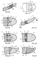
- Figure 1 is a vertical and longitudinal sectional view of the front part of a ski having an independent spatula which can slide longitudinally.
- FIG. 2 is a substantially horizontal sectional view taken along line II-II of FIG. 1.
- Figure 3 is a cross-sectional view taken along line III-III of Figure 1.
- FIG. 4 is a plan view of the front part of the ski shown in FIG. 1.
- Figures 5 and 6 are views in vertical and longitudinal section of alternative embodiments of the front part of the ski.
- Figure 7 is a plan view of another alternative embodiment of the front part of the ski.
- FIG. 8 is a view in vertical and longitudinal section of the front part of the ski shown in FIG. 7.
- Figure 9 is a vertical and longitudinal sectional view of another alternative embodiment of the front part of the ski.
- FIG. 10 is a substantially horizontal sectional view taken along the line X-X in FIG. 9.
- FIG. 11 is a plan view of the front part of the ski shown in FIG. 9.
- Figure 12 is a vertical and longitudinal sectional view of another alternative embodiment of the front part of a ski.
- FIG. 13 is a substantially horizontal sectional view taken along line XIII-XIII of FIG. 12.
- Figure 14 is a vertical and longitudinal sectional view of another alternative embodiment of the front part of a ski.
- FIG. 15 is a plan view of the front part of the ski shown in FIG. 16.
- Figures 16 and 17 are views in substantially horizontal section of alternative embodiments of the front part of the ski.
- Figure 18 is a vertical and longitudinal sectional view of an alternative embodiment of the front part of a spatula ski that can pivot about a transverse axis.
- FIG. 19 is a substantially horizontal sectional view taken along the line XXI-XXI of FIG. 20.
- Figures 20 and 21 are plan views of the front part of skis having an independent asymmetrical tip.
- the tip comprises an independent tip 2 which is mounted to slide longitudinally on the front of the ski 1.
- the tip 2 is hollowed out by a blind recess 3 extending in the plane of the 'tip 2, closed at the front by a transverse bottom 3a and which opens into the posterior front face 2a of the cap 2.
- a central tongue 4 which is an integral part of the ski 1 and which s' extends forward from the front face 1a of the ski 1 proper.
- This tongue 4 has a width or transverse dimension less than the width of the ski and its thickness is substantially equal to the vertical dimension of the recess 3 so that the end piece 2 is fitted tightly onto the tongue 4, while being able to slide on this tab.
- the front front face 4a of the tongue is located at a distance behind the bottom 3a of the recess 3 so as to leave a longitudinal play a between them allowing a slight sliding of the end piece 2 towards the rear.
- the ski tip also has an elastic element 5, forming a shock absorber, which is interposed between the rear front face 2a of the end piece 2 and the front front face 1a of the ski 1.
- the shock absorbing element 5 can be formed , as shown in the embodiment illustrated in Figures 1 to 4, by a ring of an elastic material, for example of the rubber type, which is integral with the rear end face 2a of the nozzle 2, surrounding the opening of the recess 3 into which the tongue 4 enters.
- the elastic ring 5 can be fixed to the rear front face 2a of the end piece 2 by any appropriate means, for example by overmolding or by bi-material injection.
- the end piece 2 is itself made of a relatively hard material allowing it to absorb shocks and wear.
- the tip 2 of the tip can, in the event of a frontal impact, slide backwards with respect to the ski 1, compressing the elastic element 5 forming a shock absorber.
- This sliding movement is made possible by the longitudinal play a existing between the front front face 4a of the central tongue 4 and the front transverse bottom 3a of the recess 3.
- the tip 2 of the spatula is retained forward, on the central tongue 4, by any appropriate means.
- this retention can be ensured by providing, in the two lateral faces of the tongue 4, two opposite notches 6, formed at the place where the tongue 4 is connected to the front front face 1a of the ski 1.
- the ring 5 forming shock absorber, secured to the tip 2 of the spatula is engaged elastically in the two opposite notches 6, which ensures, because the ring 5 is secured to the tip 2, the maintenance in place of this tip on the tongue 4, by "snap", in the extension of the front of the ski 1.
- the parts of the elastic ring which are engaged in the two notches 6, have convex surfaces closely matching the concave profiles of the two notches 6.
- similar notches can also be provided in the upper and lower faces of the tongue 4 so that the elastic ring 5 is anchored on the four faces of the tongue 4.
- the recess 3 and the tongue 4 may each have a rectangular shape or, which is preferable, an isosceles trapezoid shape converging towards the front, as can best be seen in FIGS. 2 and 4.
- the part of the trapezoidal tongue 4 which is engaged in the recess 3, has a longitudinal dimension which is less than the depth or longitudinal dimension of the trapezoidal recess 3.
- the inclined lateral faces 4b of the trapezoidal tongue 4 have a angle of inclination between them which is greater than the angle of inclination of the two inclined lateral faces 3b of the trapezoidal recess 3.
- the longitudinal play a and the lateral play b thus allow the end piece 2 to undergo, in the event of an impact, not only a pure longitudinal movement towards the rear, in the event of a purely frontal impact, but also a complex movement of translation towards the rear and lateral pivoting, in the event of an oblique impact, this lateral pivoting being made possible as a result of the provision for lateral clearance b .
- the overall thickness of the elastic ring 5 forming a shock absorber which is equal to that of the end piece 2, in the region of its posterior front face 2a, is slightly greater than the thickness of the front of the ski 1, so that the upper and lower faces of the elastic ring 5 are slightly projecting from the upper and lower faces of the ski 1.
- the elastic ring 5 is extended towards the rear by an external peripheral lip 5a which covers, over a short distance, the upper and lower faces of the ski 1, thus ensuring continuity between the ski 1 and the elastic ring 5.
- a layer of elastic material 5b is also interposed between the upper and lower faces of the central tongue 4 and the upper and lower faces of the recess 3, in order also to create a damping of the shocks in the vertical direction.
- the central tongue 4 and the recess 3 are removed and the elastic element 5 shock absorber is then constituted by a piece of solid elastic material, extending transversely and ensuring the junction between the rear end face 2a full of the mouthpiece 2 of the tip and the front face 1a of the ski 1.
- the elastic member 5 is fixed by any suitable means, for example by gluing, to the two end faces 1a and 2a.
- the elastic element forming a shock absorber consists of a mass of elastic material 7 which fills the space delimited between the faces 3a, 3b of the recess 3 and 4a, 4b of the tongue 4.
- the retention of the endpiece 2 towards the front is obtained by bosses 8 which are formed in the zone of connection of the lateral faces 3b of the recess 3 and of the posterior front face 2a end piece 2 and which project inwards. These bosses 8 are engaged respectively in the two notches 6 provided in the lateral faces of the central tongue 4.
- the rear front face 2a of the end piece 2 defines, with the front front face 1a of the ski 1, an empty space 9 which is surrounded by a peripheral sealing lip 11, extending towards the rear, making integral part of the end piece 2.
- This lip 11 covers the four faces of the ski 1 over which it can slide.
- a frontal and / or lateral impact is absorbed by the elastic deformation of the layer of shock absorbing material 7 which is then compressed between the end piece 2 and the central tongue 4.
- the tip 2 is full and its front face 2a is extended rearward by a central tongue 4.
- the front part of the ski 1 is hollowed out by a recess 3 receiving the tongue 4 secured to the end piece 2.
- Figures 14 and 15 illustrate an alternative embodiment in which the central tongue 4 carries an upper plate 14, of elastic material, which is housed in a recess 15 formed in the upper part of the nozzle 2 constituting the spatula.
- the plate 14 is fixed, at its lower part, to the tongue 4 by any appropriate means, for example by lower pins passing through holes drilled in the tongue 4 and terminated by deformed heads 16 in the form of rivet heads.
- the plate 14 rests, by its tapered front part, on a ramp 17 inclined from bottom to top towards the front, which is formed on the upper face of the tip 2.
- this endpiece 2 causes, by moving back slightly with respect to the tongue 4, the lifting of the tapered front part of the plate 14, which then takes a curved shape towards the top, as indicated in dashes in FIG. 16.
- This deformation of the plate 14 makes it possible to absorb the impact energy and this plate then returns to its initial shape, due to its elasticity.
- Figures 16 and 17 illustrate alternative embodiments in which the elastic element forming shock absorber is constituted by a mechanical spring.
- the tip 2 is pushed forward by a leaf spring 18, forming a bending spring.
- This leaf spring 18 is arched so as to have a convex shape towards the front, to extend transversely and to bear, by its two ends, on the front front face 1a of the ski 1 and, by its convex median part. towards the front, against the posterior front face 2a of the end piece 2. Consequently, if the end piece 2 of the tip moves back under the effect of a frontal impact, it causes a crushing of the spring leaf 18 which thus receives the energy of the shock.
- the end piece 2 can be retained forwards by any appropriate means, for example by means of a vertical finger 19 secured to the tongue 4 and engaged in a longitudinal slot 21 in the end piece 2.
- the elastic element forming shock absorber can be constituted by at least one longitudinal compression spring.
- the tip 2 of the spatula is thus pushed forward by two compression springs 22 extending longitudinally and engaged, at their ends, in housings hollowed out opposite 'from each other respectively in the front front face 1a of the ski 1 and in the rear front face 2a of the tip 2 of the tip.
- Figures 18 and 19 illustrate an alternative embodiment in which the tip comprises an independent tip 23 which is articulated on the front of the ski 1, around a transverse axis 24.
- the tip 23 of the tip is biased towards its normal position, in the extension of the front of the ski 1, by one or more springs such as torsion springs 25.
- the energy of a frontal impact is absorbed by pivoting the end piece 23 of the spatula anticlockwise around the axis 24, the spring or springs 25 then playing the role of elastic shock absorbing element.
- the springs 25 ensure the return of the tip 23 of the tip in its normal position, in the extension of the ski 1, after the impact.
- FIG. 20 shows the front of a ski, the tip of which has a tip made of a rigid material 26 of asymmetrical shape, in the case of a ski more particularly suited to the practice of slalom.
- the endpiece 26 is connected to the front front face 1a of the ski 1 by means of an elastic element 27 which, when viewed in plan, has substantially the shape of a wedge or a sector of a circle.
- the apex 27a of the wedge-shaped elastic element 27 is situated in the plane of the outer edge 1b of the ski 1 and to this apex 27a is connected the convex outer edge 26a of the end piece 26.
- the elastic element 27 has, on the side opposite its top 27a, an edge 27b which ensures continuity between the internal edge 1c of the ski 1 and the concave internal edge 26b of the endpiece 26.
- the tip 26 of asymmetrical shape is made of elastic material and it is connected to the front end face 1a of the ski 1.
- This tip 26 has, on the side of the internal edge 1c of the ski 1, a concave edge 26b and on its convex outer edge is attached a curved element 28, made of hard impact-resistant material, which extends from the end of the nozzle 26, to the point of connection between the front wall anterior 1a of the ski 1 and its outer edge 1b.
Abstract
Description
La présente invention concerne un ski et plus particulièrement un perfectionnement de son extrémité avant.The present invention relates to a ski and more particularly to an improvement of its front end.
Un ski alpin, de randonnée ou de fond se termine, à l'avant, par une spatule qui est incurvée vers le haut de manière à faciliter la glisse du ski sur la neige. Cette spatule qui se termine généralement en pointe, fait partie intégrante du reste du ski et de ce fait elle peut provoquer des blessures sérieuses à un autre skieur, dans le cas d'un choc frontal avec ce dernier. Par ailleurs une telle spatule rigide, formant une seule pièce avec le reste du ski, peut déstabiliser le skieur ou même provoquer sa chute si elle vient à heurter un piquet lorsque le skieur effectue une descente balisée par de tels piquets (épreuve de slalom par exemple). En outre les chocs frontaux encaissés par la spatule sont transmis à l'ensemble du ski et il peut en résulter une dégradation de ce dernier.Alpine, cross-country or cross-country skiing ends at the front with a spatula which is curved upwards so as to facilitate sliding of the ski over snow. This tip, which generally ends in a point, is an integral part of the rest of the ski and therefore it can cause serious injury to another skier, in the event of a frontal impact with the latter. Furthermore, such a rigid spatula, forming a single piece with the rest of the ski, can destabilize the skier or even cause his fall if it comes to strike a stake when the skier makes a descent marked by such stakes (slalom test for example ). In addition, the frontal shocks received by the tip are transmitted to the entire ski and this may result in degradation of the latter.
Le document EP-A1-0298885 concerne un ski de piste dont la spatule est tronquée et prolongée par un embout déviateur rapporté ou intégré à la structure du ski.Document EP-A1-0298885 relates to a piste ski, the tip of which is truncated and extended by a deflecting end piece added or integrated into the structure of the ski.
Le document EP-A2-0229608 décrit une invention concernant un ski dont la spatule est réalisée sous forme d'un élément élastique rapporté ; la matière plastique constituant l'élément étant choisie pour permettre d'adapter l'élasticité et/ou la raideur de la spatule.Document EP-A2-0229608 describes an invention relating to a ski, the tip of which is produced in the form of an attached elastic element; the plastic material constituting the element being chosen to allow to adapt the elasticity and / or the stiffness of the spatula.
La présente invention vise à remédier à ces divers inconvénients.The present invention aims to remedy these various drawbacks.
A cet effet ce ski comportant, à l'avant, une spatule, est caractérisé en ce que sa spatule est constituée par une pièce indépendante du ski proprement dit, montée mobile par rapport à l'avant du ski, et par au moins un élément élastique interposé entre la pièce indépendante mobile et l'avant du ski proprement dit.To this end, this ski comprising, at the front, a spatula, is characterized in that its spatula is constituted by a part independent of the ski itself, mounted movable relative to the front of the ski, and by at least one element. elastic interposed between the independent moving part and the front of the ski itself.
On décrira ci-après, à titre d'exemples non limitatifs, diverses formes d'exécution de la présente invention, en référence au dessin annexé sur lequel :Various embodiments of the present invention will be described below, by way of nonlimiting examples, with reference to the appended drawing in which:
La figure 1 est une vue en coupe verticale et longitudinale de la partie avant d'un ski comportant une spatule indépendante pouvant coulisser longitudinalement.Figure 1 is a vertical and longitudinal sectional view of the front part of a ski having an independent spatula which can slide longitudinally.
La figure 2 est une vue en coupe sensiblement horizontale faite suivant la ligne II-II de la figure 1.FIG. 2 is a substantially horizontal sectional view taken along line II-II of FIG. 1.
La figure 3 est une vue en coupe transversale faite suivant la ligne III-III de la figure 1.Figure 3 is a cross-sectional view taken along line III-III of Figure 1.
La figure 4 est une vue en plan de la partie avant du ski représentée sur la figure 1.FIG. 4 is a plan view of the front part of the ski shown in FIG. 1.
Les figures 5 et 6 sont des vues en coupe verticale et longitudinale de variantes d'exécution de la partie avant du ski.Figures 5 and 6 are views in vertical and longitudinal section of alternative embodiments of the front part of the ski.
La figure 7 est une vue en plan d'une autre variante d'exécution de la partie avant du ski.Figure 7 is a plan view of another alternative embodiment of the front part of the ski.
La figure 8 est une vue en coupe verticale et longitudinale de la partie avant du ski représentée sur la figure 7.FIG. 8 is a view in vertical and longitudinal section of the front part of the ski shown in FIG. 7.
La figure 9 est une vue en coupe verticale et longitudinale d'une autre variante d'exécution de la partie avant du ski.Figure 9 is a vertical and longitudinal sectional view of another alternative embodiment of the front part of the ski.
La figure 10 est une vue en coupe sensiblement horizontale faite suivant la ligne X-X de la figure 9.FIG. 10 is a substantially horizontal sectional view taken along the line X-X in FIG. 9.
La figure 11 est une vue en plan de la partie avant du ski représentée sur la figure 9.FIG. 11 is a plan view of the front part of the ski shown in FIG. 9.
La figure 12 est une vue en coupe verticale et longitudinale d'une autre variante d'exécution de la partie avant d'un ski.Figure 12 is a vertical and longitudinal sectional view of another alternative embodiment of the front part of a ski.
La figure 13 est une vue en coupe sensiblement horizontale faite suivant la ligne XIII-XIII de la figure 12.FIG. 13 is a substantially horizontal sectional view taken along line XIII-XIII of FIG. 12.
La figure 14 est une vue en coupe verticale et longitudinale d'une autre variante d'exécution de la partie avant d'un ski.Figure 14 is a vertical and longitudinal sectional view of another alternative embodiment of the front part of a ski.
La figure 15 est une vue en plan de la partie avant du ski représentée sur la figure 16.FIG. 15 is a plan view of the front part of the ski shown in FIG. 16.
Les figures 16 et 17 sont des vues en coupe sensiblement horizontale de variantes d'exécution de la partie avant du ski.Figures 16 and 17 are views in substantially horizontal section of alternative embodiments of the front part of the ski.
La figure 18 est une vue en coupe verticale et longitudinale d'une variante d'exécution de la partie avant d'un ski à spatule pouvant pivoter autour d'un axe transversal.Figure 18 is a vertical and longitudinal sectional view of an alternative embodiment of the front part of a spatula ski that can pivot about a transverse axis.
La figure 19 est une vue en coupe sensiblement horizontale faite suivant la ligne XXI-XXI de la figure 20.FIG. 19 is a substantially horizontal sectional view taken along the line XXI-XXI of FIG. 20.
Les figures 20 et 21 sont des vues en plan de la partie avant de skis comportant un embout indépendant dissymétrique.Figures 20 and 21 are plan views of the front part of skis having an independent asymmetrical tip.
Sur les figures 1 à 4 est représentée la partie avant d'un ski 1 qui se termine par une spatule. Suivant l'invention, la spatule comprend un embout indépendant 2 qui est monté à coulissement longitudinal sur l'avant du ski 1. A cet effet, I'embout 2 est creusé d'un évidement borgne 3 s'étendant dans le plan de l'embout 2, fermé à l'avant par un fond transversal 3a et qui débouche dans la face frontale postérieure 2a de l'ambout 2. Dans cet évidement 3 est engagée une languette centrale 4 qui fait partie intégrante du ski 1 et qui s'étend vers l'avant à partir de la face frontale antérieure 1a du ski 1 proprement dit. Cette languette 4 a une largeur ou dimension transversale inférieure à la largeur du ski et son épaisseur est sensiblement égale à la dimension verticale de l'évidement 3 de manière que l'embout 2 soit emboîté étroitement sur la languette 4, en pouvant toutefois coulisser sur cette languette. A cet effet la face frontale antérieure 4a de la languette est située à distance en arrière du fond 3a de l'évidement 3 de manière à laisser ainsi un jeu longitudinal a entre eux permettant un léger coulissement de l'embout 2 vers l'arrière.In Figures 1 to 4 is shown the front part of a
La spatule du ski comporte également un élément élastique 5, formant amortisseur de choc, qui est interposé entre la face frontale postérieure 2a de l'embout 2 et la face frontale antérieure 1a du ski 1. L'élément 5 amortisseur de choc peut être constitué, comme il est représenté dans la forme d'exécution illustrée sur les figures 1 à 4, par un anneau en un matériau élastique, par exemple du genre caoutchouc, qui est solidaire de la face frontale postérieure 2a de l'embout 2, en entourant l'ouverture de l'évidement 3 dans lequel pénètre la languette 4. L'anneau élastique 5 peut être fixé à la face frontale postérieure 2a de l'embout 2 par tous moyens appropriés, par exemple par surmoulage ou par injection bi-matière. L'embout 2 est, lui, réalisé en un matériau relativement dur permettant d'encaisser les chocs et l'usure. D'après la description qui précède, on peut voir que l'embout 2 de la spatule peut, en cas de choc frontal, coulisser vers l'arrière par rapport au ski 1, en comprimant l'élément élastique 5 formant amortisseur de choc. Ce mouvement de coulissement est rendu possible grâce au jeu longitudinal a existant entre la face frontale antérieure 4a de la languette centrale 4 et le fond transversal antérieur 3a de l'évidement 3.The ski tip also has an
L'embout 2 de la spatule est retenu vers l'avant, sur la languette centrale 4, par tous moyens appropriés. Par exemple cette retenue peut être assurée en prévoyant, dans les deux faces latérales de la languette 4, deux encoches opposées 6, formées à l'endroit où la languette 4 se raccorde à la face frontale antérieure 1a du ski 1. L'anneau 5 formant amortisseur de choc, solidaire de l'embout 2 de la spatule, est engagé élastiquement dans les deux encoches opposées 6, ce qui assure, du fait que l'anneau 5 est solidaire de l'embout 2, le maintien en place de cet embout sur la languette 4, par "encliquetage", dans le prolongement de l'avant du ski 1. De préférence, les parties de l'anneau élastique qui sont engagées dans les deux encoches 6, présentent des surfaces convexes épousant étroitement les profils concaves des deux encoches 6. Par ailleurs, des encoches similaires peuvent être prévues également dans les faces supérieure et inférieure de la languette 4 de manière que l'anneau élastique 5 soit ancré sur les quatre faces de la languette 4.The
Vus en plan, l'évidement 3 et la languette 4 peuvent avoir chacun une forme rectangulaire ou, ce qui est préférable, une forme de trapèze isocèle convergeant vers l'avant, comme on peut mieux le voir sur les figures 2 et 4. La partie de la languette trapézoïdale 4 qui est engagée dans l'évidement 3, a une dimension longitudinale qui est inférieure à la profondeur ou dimension longitudinale de l'évidement trapézoïdal 3. Par ailleurs, les faces latérales inclinées 4b de la languette trapézoïdale 4 présentent un angle d'inclinaison entre elles qui est supérieur à l'angle d'inclinaison des deux faces latérales inclinées 3b de l'évidement trapézoïdal 3. Il en résulte qu'entre la languette 4 et l'embout 2, il existe non seulement le jeu longitudinal a, entre la petite base antérieure 4a de la languette 4 et le fond 3a de l'évidement 3, mais encore un jeu latéral b entre les faces inclinées 3b et 4b, ce jeu allant en croissant de zéro à l'endroit de la face frontale postérieure 2a jusqu'à une valeur maximale dans le plan transversal de la petite base 4a. Le jeu longitudinal a et le jeu latéral b permettent ainsi à l'embout 2 de subir, en cas de choc, non seulement un mouvement longitudinal pur vers l'arrière, en cas de choc purement frontal, mais encore un mouvement complexe de translation vers l'arrière et de pivotement latéral, en cas de choc oblique, ce pivotement latéral étant rendu possible par suite de la prévision du jeu latéral b.Seen in plan, the
Dans la forme d'exécution représentée sur les figures 1 à 4, l'épaisseur globale de l'anneau élastique 5 formant amortisseur de choc qui est égale à celle de l'embout 2, dans la zone de sa face frontale postérieure 2a, est un peu supérieure à l'épaisseur de l'avant du ski 1, si bien que les faces supérieure et inférieure de l'anneau élastique 5 se trouvent légèrement en saillie par rapport aux faces supérieure et inférieure du ski 1. Dans la variante d'exécution représentée sur la figure 5, l'anneau élastique 5 est prolongé vers l'arrière par une lèvre périphérique externe 5a qui coiffe, sur une faible distance, les faces supérieure et inférieure du ski 1, en assurant ainsi la continuité entre le ski 1 et l'anneau élastique 5.In the embodiment shown in FIGS. 1 to 4, the overall thickness of the
Dans la variante de réalisation représentée sur la figure 6, une couche de matériau élastique 5b est également interposée entre les faces supérieure et inférieure de la languette centrale 4 et les faces supérieure et inférieure de l'évidement 3, afin de créer également un amortissement des chocs dans le sens vertical.In the alternative embodiment shown in FIG. 6, a layer of elastic material 5b is also interposed between the upper and lower faces of the
Suivant une autre variante représentée sur les figures 7 et 8, la languette centrale 4 et l'évidement 3 sont supprimés et l'élément élastique 5 amortisseur de choc est alors constitué par une pièce en matière élastique pleine, s'étendant transversalement et assurant la jonction entre la face frontale postérieure pleine 2a de l'embout 2 de la spatule et la face frontale antérieure 1a du ski 1. L'élément élastique 5 est fixé par tous moyens appropriés, par exemple par collage, aux deux faces frontales 1a et 2a.According to another variant shown in Figures 7 and 8, the
Dans la variante d'exécution représentée sur les figures 9, 10 et 11, l'élément élastique formant amortisseur de choc est constitué par une masse de matériau élastique 7 qui remplit l'espace délimité entre les faces 3a, 3b de l'évidement 3 et 4a, 4b de la languette 4. La retenue de l'embout 2 vers l'avant est obtenue par des bossages 8 qui sont formés dans la zone de raccordement des faces latérales 3b de l'évidement 3 et de la face frontale postérieure 2a de l'embout 2 et qui sont en saillie vers l'intérieur. Ces bossages 8 sont engagés respectivement dans les deux encoches 6 prévues dans les faces latérales de la languette centrale 4. Du fait de cette construction, la face frontale postérieure 2a de l'embout 2 délimite, avec la face frontale antérieure 1a du ski 1, un espace vide 9 qui est entouré par une lèvre d'étanchéité périphérique 11, s'étendant vers l'arrière, faisant partie intégrante de l'embout 2. Cette lèvre 11 coiffe les quatre faces du ski 1 sur lesquelles elle peut glisser. Dans cette forme d'exécution de l'invention, un choc frontal et/ou latéral est encaissé par la déformation élastique de la couche de matériau amortisseur de choc 7 qui est alors comprimée entre l'embout 2 et la languette centrale 4.In the alternative embodiment shown in FIGS. 9, 10 and 11, the elastic element forming a shock absorber consists of a mass of elastic material 7 which fills the space delimited between the
Dans la variante représentée sur les figures 12 et 13, l'embout 2 est plein et sa face frontale 2a est prolongée vers l'arrière par une languette centrale 4. De son côté, la partie avant du ski 1 est creusée d'un évidement 3 recevant la languette 4 solidaire de l'embout 2.In the variant shown in Figures 12 and 13, the
Les figures 14 et 15 illustrent une variante d'exécution dans laquelle la languette centrale 4 porte une plaquette supérieure 14, en matériau élastique, qui est logée dans un évidement 15 formé dans la partie supérieure de l'embout 2 constituant la spatule. La plaquette 14 est fixée, à sa partie inférieure, à la languette 4 par tous moyens appropriés, par exemple par des ergots inférieurs traversant des trous percés dans la languette 4 et terminés par des têtes déformées 16 en forme de têtes de rivets. La plaquette 14 repose, par sa partie avant effilée, sur une rampe 17 inclinée de bas en haut vers l'avant, laquelle est formée sur la face supérieure de l'embout 2. Par conséquent, si l'embout 2 de la spatule est sollicité vers l'arrière dans le cas d'un choc frontal, cet embout 2 provoque, en reculant quelque peu par rapport à la languette 4, le soulèvement de la partie avant effilée de la plaquette 14, qui prend alors une forme incurvée vers le haut, comme il est indiqué en tirets sur la figure 16. Cette déformation de la plaquette 14 permet d'encaisser l'énergie du choc et cette plaquette reprend ensuite sa forme initiale, du fait de son élasticité.Figures 14 and 15 illustrate an alternative embodiment in which the
Les figures 16 et 17 illustrent des variantes d'exécution dans lesquelles l'élément élastique formant amortisseur de choc est constitué par un ressort mécanique. Dans le cas de la figure 16, l'embout 2 est repoussé vers l'avant par une lame de ressort 18, formant ressort de flexion. Cette lame de ressort 18 est cambrée de manière à avoir une forme convexe vers l'avant, à s'étendre transversalement et à prendre appui, par ses deux extrémités, sur la face frontale antérieure 1a du ski 1 et, par sa partie médiane convexe vers l'avant, contre la face frontale postérieure 2a de l'embout 2. Par conséquent, si l'embout 2 de la spatule recule sous l'effet d'un choc frontal, il provoque un écrasement de la lame de ressort 18 qui encaisse ainsi l'énergie du choc. L'embout 2 peut être retenu vers l'avant par tous moyens appropriés, par exemple au moyen d'un doigt vertical 19 solidaire de la languette 4 et engagé dans une lumière longitudinale 21 de l'embout 2.Figures 16 and 17 illustrate alternative embodiments in which the elastic element forming shock absorber is constituted by a mechanical spring. In the case of Figure 16, the
Suivant une variante d'exécution, l'élément élastique formant amortisseur de choc peut être constitué par au moins un ressort de compression longitudinal. Dans la forme d'exécution représentée sur la figure 17, l'embout 2 de la spatule est ainsi repoussé vers l'avant par deux ressorts de compression 22 s'étendant longitudinalement et engagés, à leurs extrémités, dans des logements creusés en regard l'un de l'autre respectivement dans la face frontale antérieure 1a du ski 1 et dans la face frontale postérieure 2a de l'embout 2 de la spatule.According to an alternative embodiment, the elastic element forming shock absorber can be constituted by at least one longitudinal compression spring. In the embodiment shown in Figure 17, the
Les figures 18 et 19 illustrent une variante d'exécution dans laquelle la spatule comprend un embout indépendant 23 qui est articulé sur l'avant du ski 1, autour d'un axe transversal 24. L'embout 23 de la spatule est sollicité vers sa position normale, dans le prolongement de l'avant du ski 1, par un ou plusieurs ressorts tels que des ressorts de torsion 25. Dans ce cas, l'énergie d'un choc frontal est absorbée par pivotement de l'embout 23 de la spatule dans le sens inverse des aiguilles d'une montre autour de l'axe 24, le ou les ressorts 25 jouant alors le rôle d'élément élastique amortisseur de choc. Le ou les ressorts 25 assurent le retour de l'embout 23 de la spatule dans sa position normale, dans le prolongement du ski 1, après le choc.Figures 18 and 19 illustrate an alternative embodiment in which the tip comprises an
La figure 20 représente l'avant d'un ski dont la spatule comporte un embout en matériau rigide 26 de forme dissymétrique, dans le cas d'un ski plus particulièrement adapté à la pratique du slalom. L'embout 26 est relié à la face frontale antérieure 1a du ski 1 par l'intermédiaire d'un élément élastique 27 qui a sensiblement, vu en plan, une forme de coin ou de secteur de cercle. Le sommet 27a de l'élément élastique 27 en forme de coin est situé dans le plan du chant externe 1b du ski 1 et à ce sommet 27a se raccorde le bord externe convexe 26a de l'embout 26. L'élément élastique 27 présente, du côté opposé à son sommet 27a, un bord 27b qui assure la continuité entre le chant interne 1c du ski 1 et le bord interne concave 26b de l'embout 26.FIG. 20 shows the front of a ski, the tip of which has a tip made of a
Dans la variante d'exécution présentée sur la figure 21, l'embout 26 de forme dissymétrique est en matériau élastique et il se raccorde à la face frontale antérieure 1a du ski 1. Cet embout 26 présente, du côté du chant interne 1c du ski 1, un bord concave 26b et sur son bord externe convexe est rapporté un élément courbe 28, en matériau dur résistant aux chocs, qui s'étend de l'extrémité de l'embout 26, jusqu'au point de raccordement entre la paroi frontale antérieure 1a du ski 1 et son chant externe 1b.In the variant shown in FIG. 21, the
Claims (20)
- Ski comprising a spatula at the front, characterized in that the spatula is constituted by an element (2, 23) independent of the ski (1) itself, movably mounted in relation to the front of the ski (1), and by at least an elastic element (5, 7, 13, 14, 18, 22), inserted between the independent movable element (2, 23) and the front of the ski (1) itself.
- Ski, according to claim 1, characterised in that the independent element (2) of the spatula is constituted by a tip (2) mounted to slide longitudinally onto the front of the ski (1).
- Ski, according to claim 2, characterized in that the tip (2), with respect to the ski (1), is hollowed with a blind recess (3) comprising a bottom (3a), and which opens into the posterior frontal face (2a) of the tip (2), with respect to the anterior frontal face (1a) of the ski (1); a central tongue (4), integral to the ski (1), with respect to the tip (2), is engaged in this recess (3) and extends from the anterior frontal face (1a) of the ski (1) itself, with respect to to the posterior frontal face (2a) of the tip (2).
- Ski, according to claim 3, characterized in that the width or transverse dimension of the tongue (4) is less than the width of the ski, and its thickness is substantially equal to the vertical dimension of the recess (3) such that the tongue (4) is tightly nested in the recess (3).
- Ski, according to claim 4, characterized in that the frontal face (4a) of the tongue (4) is located at a distance from the bottom (3a) of the recess (3) so as to thus leave a longitudinal clearance (a) between them.
- Ski, according to any of claims 3-5, characterized in that, from a plane view, the recess (3) and the tongue (4) each have the shape of an isosceles trapezoid, and the inclined lateral faces (4b) of the trapezoidal tongue (4) have an angle of inclination between them which is greater than the relative angle of inclination of the two inclined lateral faces (3b) of the trapezoidal recess (3).
- Ski, according to any of claims 3-5, characterized in that the tip (2) is made of a hard material, resistant to shock and wear; the shock absorbing element (5) is constituted by a ring made of an elastic material, such as rubber, which surrounds the opening of the recess (3) into which the tongue (4) penetrates.
- Ski, according to claim 7, characterized in that the tongue (4) has two opposite notches (6) in its two lateral faces, formed where the tongue (4) joins to the anterior frontal face (1a) of the ski (1), respectively, to the frontal posterior face (2a) of the tip (2). The elastic ring (5) is engaged in the two notches opposite (6) the tongue (4).
- Ski, according to any of claims 7 and 8, characterized in that the elastic ring (5) is rearwardly extended towards by an external peripheral lip (5a) which covers the faces of the ski (1) along a short distance.
- Ski, according to any of claims 3-5, characterized in that the elastic element forming the shock absorber is constituted by a mass of elastic material (7) which fills the space demarcated between the faces (3a, 3b) of the recess (3) and the faces (4a, 4b) of the tongue (4).
- Ski, according to claim 10, characterized in that bosses (8) projecting inwardly are formed in the connecting zone of the lateral faces (3b) of the recess (3) and the posterior frontal face (2a) of the tip (2); and these bosses (8) are engaged respectively in two notches (6) provided in the lateral faces of the central tongue (4).
- Ski, according to any of claims 10 and 11, characterized in that the posterior frontal face (2a) of the tip (2) together with the anterior frontal face (1a) of the ski (1), demarcates a hollow/empty space (9) which is surrounded by a peripheral lip (11) extending towards the rear and integral to the tip (2), and which covers the faces of the ski (1) on which it can slide.
- Ski, according to any of claims 3-5, characterized in that the central tongue (4) bears an upper plate (14) made of an elastic material, which is housed in a recess (15) formed inside the upper portion of the tip (2); the plate (14) is affixed to the tongue (4) at its lower portion, and rests, via its tapered portion, on a ramp formed on the upper face of the tip (2) and inclined from the base up towards the front.
- Ski, according to any of claims 3-5, characterized in that the elastic element forming the shock absorber is constituted by a mechanical spring (18, 22).
- Ski, according to claim 14, characterized in that the spring (18) is constituted by an arched flexion blade such that it has a convexed shape towards the front, extends transversely and takes support in the anterior frontal face of the ski (1) via its two ends, and against the posterior frontal face (2a) of the tip (2) by its median convex portion towards the front.
- Ski, according to claim 15, characterized in that the elastic element forming the shock absorber is constituted by at least one longitudinal compression spring (22).
- Ski, according to claim 1, characterized in that the independent element (23) of the spatula is constituted by a tip which is journalled on the front of the ski (1) about a transverse axis (24) while being biased by an elastic return element (25).
- Ski, according to claim 1, characterized in that the independent element (26) of the spatula is constituted by a tip having an asymmetrical shape.
- Ski, according to claim 18, characterized in that the asymmetrical tip (26) made of a rigid material, is connected to the anterior frontal face (1a) of the ski (1) by means of an elastic element (27) which, from a substantially plane view, is shaped substantially like a wedge or sector of a circle.
- Ski, according to claim 18, characterized in that the asymmetrical tip (26) made of an elastic material is joined to the anterior frontal face (1a) of the ski (1) and has a curved attached element (28) made of a hard, shock resistant material on its convex edge, which joins to the external edge (1b) of the ski (1).
Applications Claiming Priority (2)
| Application Number | Priority Date | Filing Date | Title |
|---|---|---|---|
| FR9006183A FR2662092B1 (en) | 1990-05-17 | 1990-05-17 | SKI. |
| FR9006183 | 1990-05-17 |
Publications (2)
| Publication Number | Publication Date |
|---|---|
| EP0456980A1 EP0456980A1 (en) | 1991-11-21 |
| EP0456980B1 true EP0456980B1 (en) | 1994-06-08 |
Family
ID=9396708
Family Applications (1)
| Application Number | Title | Priority Date | Filing Date |
|---|---|---|---|
| EP91103657A Expired - Lifetime EP0456980B1 (en) | 1990-05-17 | 1991-03-11 | Ski |
Country Status (4)
| Country | Link |
|---|---|
| EP (1) | EP0456980B1 (en) |
| AT (1) | ATE106763T1 (en) |
| DE (1) | DE69102349T2 (en) |
| FR (1) | FR2662092B1 (en) |
Families Citing this family (7)
| Publication number | Priority date | Publication date | Assignee | Title |
|---|---|---|---|---|
| FR2685215B1 (en) * | 1991-12-19 | 1994-10-21 | Rossignol Sa | SKI SPATULA MOUTHPIECE. |
| FR2685214B1 (en) * | 1991-12-19 | 1995-05-19 | Rossignol Sa | SKI SPATULA MOUTHPIECE. |
| AT401733B (en) * | 1992-04-01 | 1996-11-25 | Eder Walter | CROSS-COUNTRY SKI |
| FR2694889B1 (en) * | 1992-08-24 | 1994-10-14 | Rossignol Sa | Ski comprising a body and at least one end piece, tip and / or heel produced independently, and method of manufacturing such a ski. |
| FR2700478B1 (en) * | 1993-01-21 | 1995-03-03 | Rossignol Sa | Method for manufacturing a ski with attached end (s) and ski thus produced. |
| FR2737128B1 (en) * | 1995-07-27 | 1997-08-22 | Rossignol Sa | SPATULA MOUTHPIECE FOR SLIDING BOARD, AND SLIDING BOARD EQUIPPED WITH SUCH A MOUTHPIECE |
| FR2983416B1 (en) * | 2011-12-05 | 2015-02-20 | Rossignol Sa | BOARD OF SLIDERS |
Family Cites Families (5)
| Publication number | Priority date | Publication date | Assignee | Title |
|---|---|---|---|---|
| US3820802A (en) * | 1972-05-17 | 1974-06-28 | L Davis | Ski adapter combination for free style maneuvering |
| IT1180985B (en) * | 1984-05-25 | 1987-09-23 | Caber Italia | ANTIVIBRATION FRONT FOR SKI |
| AT389452B (en) * | 1986-01-10 | 1989-12-11 | Head Sportgeraete Gmbh | SKI |
| US4674763A (en) * | 1986-04-14 | 1987-06-23 | Albert Schlagenhaufer | Ski damping device |
| FR2617729B1 (en) * | 1987-07-09 | 1989-11-10 | Rossignol Sa | LONG SPATULA TRACK SKI |
-
1990
- 1990-05-17 FR FR9006183A patent/FR2662092B1/en not_active Expired - Fee Related
-
1991
- 1991-03-11 DE DE69102349T patent/DE69102349T2/en not_active Expired - Fee Related
- 1991-03-11 AT AT91103657T patent/ATE106763T1/en not_active IP Right Cessation
- 1991-03-11 EP EP91103657A patent/EP0456980B1/en not_active Expired - Lifetime
Also Published As
| Publication number | Publication date |
|---|---|
| FR2662092A1 (en) | 1991-11-22 |
| FR2662092B1 (en) | 1992-08-28 |
| DE69102349D1 (en) | 1994-07-14 |
| EP0456980A1 (en) | 1991-11-21 |
| ATE106763T1 (en) | 1994-06-15 |
| DE69102349T2 (en) | 1994-09-29 |
Similar Documents
| Publication | Publication Date | Title |
|---|---|---|
| EP1166668A2 (en) | Sportsshoe with a rigid heel stiffener fixed on a flexible heel stiffener | |
| EP0609543B1 (en) | Ski with a damping device | |
| EP0560695A1 (en) | Device comprising a front and a heel binding independant from each other | |
| EP0465794A1 (en) | Ski with a fileted upper surface | |
| WO1988005675A1 (en) | Ski for cross-country skiing | |
| EP0456980B1 (en) | Ski | |
| EP1108450B1 (en) | Device for retaining a shoe on a gliding board | |
| FR2642980A1 (en) | Binding device for a cross-country ski and boot intended for such a binding device | |
| FR2926735A1 (en) | ALPINE SKI WITH MEANS OF ADJUSTMENT | |
| FR2537010A1 (en) | Binding for cross-country ski | |
| WO1996036407A1 (en) | Device for holding a boot on a snowboard | |
| FR2768938A1 (en) | Snow shoe | |
| CA2021947C (en) | Cross-country ski binding and elastic stopper for same | |
| CH667977A5 (en) | SKI SHOE WITH REAR ENTRY. | |
| EP1013316B1 (en) | Alpine ski | |
| CH673400A5 (en) | ||
| CH660976A5 (en) | SECURITY FIXING FOR SKIING. | |
| WO2006024711A1 (en) | Safety stirrup | |
| EP1433504A1 (en) | Device for fixing a shoe on a sporting good | |
| FR2669236A1 (en) | ALPINE SKI SAFETY ATTACHMENT. | |
| FR2880547A1 (en) | Top wedging and rotation blocking device for snowshoe`s fixing plate, has sliding unit moved in translation by front and rear connecting rods in order to occupy engaged and disengaged positions | |
| EP2959949B1 (en) | Device for accommodating a shoe on a snow gliding device | |
| EP2578277B1 (en) | Heelpiece of a safety binding for ski boot | |
| FR2810206A1 (en) | FOOTWEAR FOR SNOW SURFING | |
| FR2759600A1 (en) | Plate to raise boot bindings above ski |
Legal Events
| Date | Code | Title | Description |
|---|---|---|---|
| PUAI | Public reference made under article 153(3) epc to a published international application that has entered the european phase |
Free format text: ORIGINAL CODE: 0009012 |
|
| AK | Designated contracting states |
Kind code of ref document: A1 Designated state(s): AT DE |
|
| 17P | Request for examination filed |
Effective date: 19920504 |
|
| 17Q | First examination report despatched |
Effective date: 19930427 |
|
| GRAA | (expected) grant |
Free format text: ORIGINAL CODE: 0009210 |
|
| AK | Designated contracting states |
Kind code of ref document: B1 Designated state(s): AT DE |
|
| REF | Corresponds to: |
Ref document number: 106763 Country of ref document: AT Date of ref document: 19940615 Kind code of ref document: T |
|
| REF | Corresponds to: |
Ref document number: 69102349 Country of ref document: DE Date of ref document: 19940714 |
|
| PG25 | Lapsed in a contracting state [announced via postgrant information from national office to epo] |
Ref country code: AT Effective date: 19950311 |
|
| PLBE | No opposition filed within time limit |
Free format text: ORIGINAL CODE: 0009261 |
|
| STAA | Information on the status of an ep patent application or granted ep patent |
Free format text: STATUS: NO OPPOSITION FILED WITHIN TIME LIMIT |
|
| 26N | No opposition filed | ||
| PG25 | Lapsed in a contracting state [announced via postgrant information from national office to epo] |
Ref country code: DE Effective date: 19951201 |